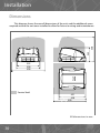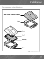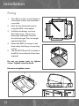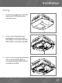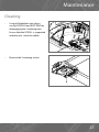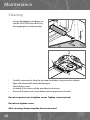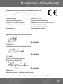
1
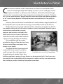
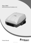
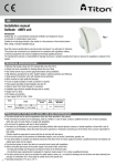
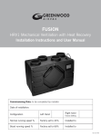
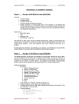
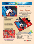
Titon CME1 Q Plus
Mechanical Extract Ventilation Unit
Product Manual
ventilation systems
PCT Patent Application No PCT/GB2009/000114
2
Contents
This is the Product Manual for the Titon CME1 Q Plus
Introduction . . . . . . . . . . . . . . .
Ventilation is Vital . . . . . . . . . . . .
How the System Works . . . . . . . . . .
How to Use the System. . . . . . . . . .
Product Features . . . . . . . . . .
Installation
Safety and Guidance . . . . . . . .
Transportation, Packaging & Storage .
Inspection . . . . . . . . . . . . .
Parts List . . . . . . . . . . . . . .
Preparation . . . . . . . . . . . . .
Dimensions . . . . . . . . . . . . .
Component Identification . . . . . .
Fixing . . . . . . . . . . . . . . .
Ducting Best Practice . . . . . . . .
Ducting Connection. . . . . . . . . . . .
Wiring . . . . . . . . . . . . . . .
Quick Commission
Quick Commission Mode . . . . . .
Full Commission Mode . . . . . . . . . .
Full Commission Mode . . . . . . .
Continuous Speed Setting . . . . . .
Boost Speed setting . . . . . . . . .
Resetting the Controller . . . . . . .
Maintenance
Cleaning . . . . . . . . . . . . . .
Declaration of Conformity . . . . . . . .
Service Record . . . . . . . . . . . . . .
.
.
.
.
.
.
.
.
.
.
.
.
.
.
.
.
.
.
.
.
.
.
.
.
.
.
.
.
.
.
.
.
.
.
.
.
.
.
.
.
.
.
.
.
.
.
.
.
.
.
.
.
.
.
.
.
.
.
.
.
.
.
.
.
.
.
.
.
.
.
.
.
.
.
.
.
.
.
.
.
.
.
.
.
.
.
.
.
.
.
.
.
.
.
.
.
.
.
.
.
4
5
6
7
7
.
.
.
.
.
.
.
.
.
.
.
.
.
.
.
.
.
.
.
.
.
.
.
.
.
.
.
.
.
.
.
.
.
.
.
.
.
.
.
.
.
.
.
.
.
.
.
.
.
.
.
.
.
.
.
.
.
.
.
.
.
.
.
.
.
.
.
.
.
.
.
.
.
.
.
.
.
.
.
.
.
.
.
.
.
.
.
.
.
.
.
.
.
.
.
.
.
.
.
.
.
.
.
.
.
.
.
.
.
.
.
.
.
.
.
.
.
.
.
.
.
.
.
.
.
.
.
.
.
.
.
.
.
.
.
.
.
.
.
.
.
.
.
.
.
.
.
.
.
.
.
.
.
.
.
.
.
.
.
.
.
.
.
.
.
.
.
.
.
.
.
.
.
.
.
.
.
.
.
.
.
.
.
.
.
.
.
.
.
.
.
.
.
.
.
.
.
.
.
.
.
.
.
.
.
.
.
.
.
. 8
. 9
. 9
. 9
. 9
10
11
12
14
15
18
.
.
.
.
.
.
.
.
.
.
.
.
.
.
.
.
.
.
.
.
.
.
.
.
.
.
.
.
.
.
.
.
.
.
.
.
.
.
.
.
.
.
.
.
.
.
.
.
.
.
.
.
.
.
.
.
.
.
.
.
.
.
.
.
.
.
.
.
.
.
.
.
.
.
.
.
.
.
.
.
.
.
.
.
.
.
.
.
.
.
.
.
.
.
.
.
.
.
.
.
.
.
.
.
.
.
.
.
.
.
.
.
.
.
20
22
22
22
24
25
. . . . . . . . . . . . . . . . . . . 26
. . . . . . . . . . . . . . . . . . . 29
. . . . . . . . . . . . . . . . . . . 31
3
Introduction
I
nterior comfort, air quality and energy efficiency are vitally important considerations in buildings today. The Titon CME1 has been developed to meet these demands by extracting stale polluted air from the building whilst fresh air is provided
by passive means.
For the home owner or occupant, this Product Manual explains:
•
•
•
Why ventilation is vital for the good health of your home and its occupants.
How your Titon CME1 system works.
How to operate and maintain your Titon CME1.
For the professional installer, this Product Manual explains:
•
•
•
How to install the Titon CME1.
How to commission the unit.
How to maintain the unit.
It is important to read this Product Manual to ensure your ventilation system is
installed, commissioned and used properly and continues to operate effectively.
Failure to follow the guidance provided in this manual can have an adverse effect
on health.
4
Ventilation is Vital
C
onstruction methods used in older homes resulted in uncontrolled ventilation via air leaking through the building structure, such as small gaps around
windows and doors or between walls and floors. These leaks allowed a large
amount of air to move through a home largely unnoticed by the occupants. Other factors, such as open fireplaces, people being at home more often and opening windows
to “air” rooms during daytime, all helped maintain reasonable levels of air quality in
homes.
However, because this form of ventilation was uncontrolled, a large proportion of
heat escaped to the outside and more energy was needed to make up for this loss.
Modern homes have greatly reduced air leaks and indoor air quality can deteriorate rapidly without the use of products made to control ventilation Chemicals, gases
and moisture produced by everyday
products and activities may lead to the
build up of excessive levels of pollutants
which are harmful to the health of the occupants and may damage the building.
Poor ventilation can be a major
contributory factor of heart disease, lung
disease, mental illness and many more
threats to our health.
The World Health Organisation and
responsible Governments around the
world recognise the vital importance
Ventilation an essential ingredient
of good indoor air quality. That is why
building regulations govern the way homes are designed and built. Once homes are
occupied it is the responsibility of the occupants to make sure they use and maintain
the ventilation products following the guidance provided.
5
How the System Works
T
he Titon CME1 works by continually extracting stale polluted air from rooms
where most moisture is generated. Fresh air is provided passively from outside
to habital rooms, creating a flow of fresh, clean air throughout the home. The air
travels from terminals built into the ceiling which are connected by hidden ducts to
the unit. The unit is usually installed in a roof space or cupboard.
Each unit is commissioned individually so the amount of air moved is set to suit
the specific size and style of the home.
Most systems will also have a facility to boost the extraction rate at times when
more moisture is being generated, such as when bathing or cooking. This may be
done automatically by electronic sensors or by a conveniently located boost switch for
manual operation.
Exhaust
CME1
Extract Terminals
Typical system layout
DO NOT switch off the unit; it is designed to run continuously. If the unit is switched
off indoor pollutant and moisture levels may increase and become a danger to
your health and damage your house.
It is important to follow the advice in this user manual and correctly maintain the
system to ensure a healthy indoor environment.
6
How to Use the System
T
he unit runs automatically and should not be switched off, except for maintenance. If a boost switch has been installed, it can be used to increase the extract
ventilation rate at times when moisture or pollutant levels are considered excessive. You may have electronic sensors which detect high levels of moisture and pollutants which boost the system automatically.
All ventilation units require periodic maintenance and this must only be carried
out by a suitably qualified and competent person. See the servicing and maintenance
section for further details.
Product Features
•
•
•
•
•
•
•
•
Boost Control
Compact low profile unit
Hidden installation fixings.
All duct ports on one level
Accepts 204mm x 60mm or 110mm x 54mm ducting.
Unit can be cleaned and serviced without disturbing any ducting.
Straightforward installation
Versatile Low Voltage boost control accepts any one-way switched input, such as
PIR humidistat or thermostat.
7
Installation
Safety and Guidance
•
•
•
•
•
•
The electrical installation of the appliance MUST be carried out by a suitably qualified competent person and all wiring must be in accordance with current I.E.E.
Regulations and all appropriate standards and applicable regulatory guidance.
The appliance must be connected to a local isolation switch with a contact separation of at least 3mm.
The appliance is suitable for 230V ~ 50/60Hz single phase with a fuse rating of 3A.
Ensure that external grills are located away from any flue outlet, in accordance
with relevant Building Regulations.
Always ensure ducting is free from blockages before switching the unit on.
We recommend a minimum distance of 200mm between the appliance and any
sharp bends in duct work.
Installation of the appliance MUST be carried out by a qualified and suitably
competent person and should be carried out in clean, dry conditions where dust
and humidity are at minimal levels.
The appliance is not suitable for installation to the exterior of the dwelling.
Failure to comply with any of the above points may have an impact on the validity
of your guarantee.
8
Installation
Transportation, Packaging & Storage
•
•
•
Great care should be taken when transporting the appliance, DO NOT drop as
damage may occur.
The unit must always be stored in a clean and dry environment.
Remove all packaging before installation but leaving duct port covers/bungs in
place (if fitted) until connecting ducting.
Inspection
•
•
Inspect the appliance for damage.
Check all accessories have been supplied.
Parts List
•
•
•
CME1 Unit x 1.
Port covers x 3.
Product manual x 1.
•
CME1 Screw Pack x 1.
All shortages or damage must be reported to the supplier.
Preparation
Important: read these instructions fully before the installation of this appliance
•
•
NEVER install the unit in an area which does not have sufficient access for future
maintenance, see Dimensions.
NEVER install the appliance in an environment which contains:
- Excessive oil or a grease laden environment.
- Hazardous gases, liquids or vapours that are flammable or corrosive.
- Ambient temperatures above 40°C or below -5°C.
- Humidity levels above 90% or a wet environment.
9
Installation
Dimensions
252
450
This diagram shows the overall dimensions of the unit, and the additional space
required around the unit once installed to allow for future servicing and maintenance.
355
390
590
Service Void
421
450
550
All dimensions in mm
10
Installation
Component Identification
Cover / Scroll / Inlet Ring assembly
Base
Cover
Scroll
Inlet ring
Base
CME1 Unit components
11
Installation
Fixing
3.
4.
5.
Do not use power tools to tighten
screws. Tighten screws by hand.
Do not over tighten screws.
1
2
5
4
6
12
3
260
EXTRACT
PORT
2.
The CME1 must be securely fixed to a
smooth flat surface, any orientation
is possible.
Mark the four fixing hole centres
using the BASE as a template
Drill holes for fixings, use 4mm
Pan Head screws. Always use a
fixing type and length suited to
the substrate type. The unit weighs
approximately 5kg.
Mount the BASE, ensuring it is not
distorted by the fixings or mounting
surface.
Clip the MOTOR and LID assembly to
the BASE, ensure that all 6 clips have
engaged.
260
1.
Installation
Fixing
1.
Unscrew the 2 retaining screws that
hold on the COVER and remove,
retain the screws.
2.
Fit two screws through the preformed holes at the front of the
INLET RING. to securely fix the INLET
RING/SCROLL assembly to the BASE.
3.
Fit one screw through the preformed
hole in the back of the BASE. to
securely fix the INLET RING/SCROLL
assembly to the BASE.
13
Installation
Ducting Best Practice
•
•
•
•
•
•
•
The use of flexible ducting must be kept to a minimum and it should always be
pulled taut.
If applicable, Fire Dampers must be fitted to duct work at appropriate locations in
accordance with Building Regulations.
Ducting must be installed in such a way that resistance to airflow is minimised.
Ducting terminal for Exhaust must be to the external air outside the building
envelope.
We recommend a minimum distance of 200mm between the appliance and any
sharp bends in duct work.
Ducting in unheated spaces must
always be insulated to prevent
condensation forming within the
ducting.
Additional guidance can be found in
the Residential Ventilation Association Instillation Good Practice Guide
and Approved Document Part F.
EXTRACT
PORT
Extract Port to Outside
14
Installation
Ducting Connection
•
204mm x 60mm ducting fits inside
the ports.
•
110mm x 54mm ducting fits inside
the convertible port cover
•
All joints must be adequately sealed
using a suitable ducting tape or
silicone type sealant.
15
Installation
Ducting Connection
16
•
To enable fitment of 110x54mm
ducting, modify the convertible port
cover by tearing out the ‘rip strip’.
•
When using the convertible port
cover ensure the tear out section is
completely removed.
•
Unused extract ports must be fitted
with non-converted or undamaged
port covers.
Installation
Notes
17
Installation
Wiring
WARNING: The unit MUST be earthed. All wiring must conform to current I.E.E.
Wiring Regulations and all applicable standards and Building Regulations.
•
•
•
•
•
•
•
•
•
•
The unit is suitable for 230V~50Hz Single phase supply fused at 3A.
A double pole isolation switch with contact separation of at least 3mm must be
used to connect the appliance to the fixed wiring.
Boost controls must not be located within 1 metre of a cooker or where they may
be affected by excessive heat or moisture
Boost controls should be clearly identified and conveniently located.
The boost switch wiring must not be connected to the mains supply.
The boost switch is connected to the control board (which is located under the
COVER on top of the SCROLL).
The boost switch wiring cable access is via cut outs in the COVER.
The boost switch wiring connection to be made by the 5v+ and SW terminals on
the control board.
The boost overrun can be triggered by any device which provides a one-way
switch, such as a PIR, thermostat, humidistat or a standard one-way switch.
The boost facility features a overrun timer, so we recommend a sprung-return
(momentary) switch is used to prevent the boost being accidentally left on for
longer than intended.
Double Pole Isolator
3A Fuse
L
L
N
N
Supply Wiring Diagram 230V~50Hz
18
Installation
Wiring
Cable Access
Internal Cable Routing
5V+
on dip
1 2 3 4
SW
Boost Control Wiring Diagram, Low Voltage Only
19
Quick Commissioning
T
he speed of the Titon HRV1 Q Plus will require adjustment to ensure the flow
rates achieved provide adequate ventilation in accordance with all relevant
Building Regulations and applicable Standards. The Titon HRV1 Q Plus has two
commissioning modes
Quick Commission Mode
For easy installation and setup
•
Full
Commission
Mode
For optimum efficiency and system performance.
•
Quick Commission Mode
1.
2.
3.
4.
5.
Power up the Titon CME1 Q Plus.
Gain access to the control board
located under the COVER. (see
diagram).
Select required speed setting using
switches 2 to 4 on the Speed Selection Switch. (See opposite)
Select required boost overrun using
switch 1 on the Speed Selection
Switch.
Check boost activation by triggering
the remote boost switch device.
Control Board location
on dip
Potentiometer
1 2 3 4
Speed Selection
Switches
Jumper
Boost Control
Connections
Control Board component identification
20
Quick Commissioning
Speed 1
Speed 2
Speed 3
Speed 4
on dip
on dip
on dip
on dip
1 2 3 4
1 2 3 4
1 2 3 4
1 2 3 4
12.5%
25%
37.5%
50%
Speed 5
Speed 6
Speed 7
Speed 8
on dip
1 2 3 4
62.5%
on dip
1 2 3 4
75%
on dip
1 2 3 4
87.5%
on dip
1 2 3 4
100%
Speed setting percentages relate to the total capacity of the Unit
Speed selection switch settings in Quick Commission Mode
5 minute
10 minute
on dip
on dip
1 2 3 4
1 2 3 4
Boost Overrun switch settings in Quick Commission Mode
21
Full Commissioning
Full Commission Mode
To fully commission the unit for optimum efficiency, each step below MUST be
followed in sequence:
1.
2.
Power up the Titon CME1 Q Plus.
Gain access to the control board located under the COVER.
Continuous speed setting
3.
4.
5.
Move the jumper from the STORED
position to the ON position.
Ensure the controller is in Continuous mode, switch 1 OFF.
Select required setting for continuous speed using switches 2 to 4 on
the Speed Selection Switch.
Stored
ON
Jumper Positions
on dip
Potentiometer
1 2 3 4
Speed Selection
Switches
Jumper
Boost Control
Connections
Control Board
22
Full Commissioning
Continuous Mode
on dip
1 2 3 4
Continuous Mode switch setting in Full Commission Mode
Speed 1
Speed 2
Speed 3
Speed 4
on dip
on dip
on dip
on dip
1 2 3 4
1 2 3 4
1 2 3 4
1 2 3 4
12.5%
25%
37.5%
50%
Speed 5
Speed 6
Speed 7
Speed 8
on dip
1 2 3 4
62.5%
on dip
1 2 3 4
75%
on dip
1 2 3 4
87.5%
on dip
1 2 3 4
100%
Speed setting percentages relate to the total capacity of the Unit
Continuous Speed selection switch settings in Full Commission Mode
23
Full Commissioning
Boost Speed Setting
6.
7.
8.
Select Boost mode on switch 1 ON.
Select required range for boost
speed using switches 2 to 4 on the
speed selection switch.
Fine adjustment within each speed
range can be carried out using the
potentiometer (POT) on the control
board..
Boost Mode
on dip
1 2 3 4
Boost Mode switch setting in Full
Commission Mode
Do not return switch to continuous mode as this will change the boost speed
Speed 2
Speed 1
Speed 3
Speed 4
on dip
on dip
on dip
on dip
1 2 3 4
1 2 3 4
1 2 3 4
1 2 3 4
0-12.5%
12.5-25%
25-37.5%
37.5-50%
Speed 5
Speed 6
Speed 7
Speed 8
on dip
on dip
on dip
on dip
1 2 3 4
1 2 3 4
1 2 3 4
1 2 3 4
50-62.5%
62.5-75%
75-87.5%
87.5-100%
Speed setting percentages relate to the total capacity of the Unit
Potentiometrer
postions
High
Mid
Low
Boost Speed selection switch & POT positions in Full Commission Mode
24
Full Commissioning
Boost Speed Settings
9.
Once the Continuous and Boost
speeds have been set, remove the
jumper and return to the stored
position.
10. Select required boost overrun using
switch 1 and 2 on the speed selection switch.
11. Check boost activation by triggering
the remote boost switch device.
5 minute
10 minute
Stored
ON
Jumper Positions
15 minute
20 minute
on dip
on dip
on dip
on dip
1 2 3 4
1 2 3 4
1 2 3 4
1 2 3 4
Boost Overrun selection switch settings in Full Commission Mode
Resetting the Controller
If necessary the controller can be reset into the Quick commissioning mode.
1. Place the jumper in to the ON position.
2. Switch the power to the unit OFF for at least 1 minute.
3. Switch the power to the unit back ON. The unit will now run at 50% capacity by
default.
4. Remove the jumper and place it back into it stored position.
The controller will now be in the Quick Commissioning mode.
25
Maintenance
Cleaning
The CME1 must be periodically cleaned internally. The maximum time between
cleaning will depend on the local environment, however every 3 – 4 years is recommended.
WARNING: The unit uses a 230V ~ supply and contains rotating mechanical parts.
Isolate the unit from mains power supply and allow sufficient time for all moving
parts to stop before undergoing any Servicing or Maintenance.
•
To gain access to the interior of the unit for cleaning –
•
Unscrew the 3 retaining screws that
hold on the COVER and remove
•
Remove the 4 SCROLL retaining
screws, if fitted.
3
2
4
1
26
Maintenance
Cleaning
•
Using a flat bladed screw driver,
un-clip SCROLL from INLET RING by
disengaging the 3 retaining clips.
Ensure that the SCROLL is supported
and does not strain the cables.
•
Remove the 3 retaining screws.
27
Maintenance
Cleaning
•
Using a flat bladed screwdriver, unclip the INLET RING from BASE. by
disengaging the 4 retaining clips.
1
2
2
1
4
3
•
•
•
•
•
Carefully remove dust from the unit and fan blades using a vacuum cleaner.
Wipe with damp cloth and mild detergent.
Check fixing screws.
Assembly is the reverse of the preceding instructions.
Ensure all fasteners are secure before returning power to the unit.
Do not use power tools to tighten screws. Tighten screws by hand.
Do not over tighten screws.
After servicing, always complete the service record
28
Declaration of Conformity
We declare that the equipment detailed below conforms
to the requirements of EC council directives relating to electromagnetic compatibility and safety of electrical equipment.
Equipment type:
Description of equipment:
Relevant EC Council Directives:
Applied Harmonised Standards:
Manufacturer:
Titon CME1 Q Plus
Mechanical ventilation unit
2006/95/EC (LVD), 2004/108/EC (EMC)
EN 60335-1:2002/A2:2006
EN 60335-2-80:2003/AI:2004
Titon Hardware Limited
Signature of manufacturer representatives
29 July 2009
N C Howlett
Development and Sustainability Director
29 July 2009
P S Cowell
Research and Testing Manager
BEng (Hons) CEng MCIBSE
29 July 2009
R Brighton
Managing Director - Manufacturing Division
International House, Peartree Road, Stanway, Colchester, Essex CO3 0JL
29
Service Record
Serviced by
30
Company name
Date
Notes
Service Record
Serviced by
Company name
Date
Notes
31
Installed by
Ensure this booklet is passed to the householder once installation and
commissioning of the ventilation system is complete. This Product Manual
must be kept in the Home Information Pack and used as a service record.
MARKETING DIVISION
International House, Peartree Road, Stanway, Colchester, Essex CO3 0JL
Tel: +44 (0) 1206 713800 Fax: +44 (0) 1206 543126
Email: [email protected] Web: www.titon.com
BM 834 iss02