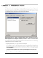
1
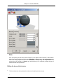
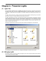
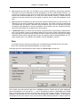
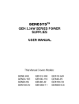
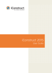
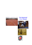
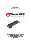
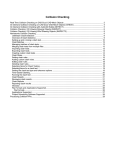
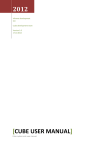
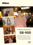
NavisWorks Presenter
User Manual
NavisWorks Presenter: User Manual
Table of Contents
1. Overview of Presenter ..............................................................................................................
2. Rendering Scenes ...................................................................................................................
3. Presenter Materials ..................................................................................................................
3.1. Materials Tab ................................................................................................................5
3.2. Applying Presenter Materials ......................................................................................... 5
3.3. Removing Presenter Materials ....................................................................................... 6
3.4. Managing Materials .......................................................................................................7
3.5. Editing Presenter Materials ............................................................................................ 8
3.6. Advanced Materials .......................................................................................................10
4. Presenter Lights .......................................................................................................................
4.1. Lights Tab .....................................................................................................................12
4.2. Managing Lights ............................................................................................................12
4.3. Editing Lights ................................................................................................................13
4.4. Predefined Light Studios ................................................................................................ 15
4.5. Advanced Lighting .........................................................................................................15
4.5.1. Soft Shadows .....................................................................................................15
4.5.2. Physically Accurate Lights ................................................................................... 16
4.5.3. Volumetric Lights ................................................................................................16
5. Rendering Effects ....................................................................................................................
5.1. Effects Tab ...................................................................................................................18
5.2. Background Effects .......................................................................................................19
5.3. Foreground Effects ........................................................................................................19
5.4. Rendering Styles ...........................................................................................................20
5.5. Predefined Rendering Styles .......................................................................................... 21
6. Texture Space .........................................................................................................................
7. Presenter Rules .......................................................................................................................
Index ..........................................................................................................................................
iv
Chapter 1. Overview of Presenter
The Presenter plugin enables you to set up materials and lights in your scene and render it with more realism and effects. Like all plugins, Presenter is a dockable tabbed control bar accessed through the Tools
menu (Hint: hold down the Control key to prevent the control bar from docking if necessary). From the
Presenter control bar you can edit pre-defined materials and apply them to items in the scene, add lights
to the scene and set up rules for applying the materials to other files in the same project set up with the
same parameters. You can define and apply your materials and lights to a model and save the settings
into a NavisWorks .nwf file so that as the model is updated, the materials and lights remain the same. Materials can also be brought through from CAD applications via the .3DS and .dgn file formats, or by exporting from 3D Studio Viz or Max (see the chapter called "Converting Files" in the Roamer book for more
details on this).
While Presenter can be used for photorealistic renderings, it can also be used for OpenGL interactive rendering and once you've set up the scene with Presenter, you can view the materials and lights in Roamer.
There are special rendering styles to interactively preview the Presenter materials and lights called Full
Lights and Full Render on the Rendering Style toolbar:
The Materials, Lights and Effects tabs are divided into two panes. The left hand pane contains the
archives and the right hand pane contains the scene's palette, which defines what materials, lights and effects are used in the scene. Archives are shown in a tree structure and are defined in the LightWorks
Archive (.lwa) format.
There are three pre-defined archives that are installed with Presenter:
•
The Interactive archive contains materials, lights and effects which can be seen during interactive
navigation in NavisWorks Roamer and can be fully rendered with OpenGL. Of course, they will look
better when rendered photorealistically.
•
Materials, lights and effects in the Photorealistic archive cannot be fully reproduced using OpenGL
and therefore will not be seen properly in interactive mode, or until a full photorealistic render is done.
•
Any materials, lights and effects from any archive can be used as a template starter for your own definitions, but the Templates archive contains instances of each type of material, light and effect, giving
you quicker access.
Additional .lwa archives can be downloaded from http:\\www.lightworks-user.com. Although materials,
lights and effects cannot be edited in archives, once dragged into the scene's palette, they can be edited
and saved with the scene in a NavisWorks .nwd or .nwf file.
You can save your own edits to materials into an .nwp file - see Section 3.4 for more information on how
to do this. Also, there is a User archive, which allows you to save your own edited materials, lights and effects, for use in other scenes.
The User Archive
The User archive is accessible from each of the Materials, Lights and Effects tabs. The principles are
the same for each.
Managing the user archive
1
Chapter 1. Overview of Presenter
1.
To save a material, light or effect to the user archive for use in other scenes, simply drag that item
onto the User archive.
2.
To create a new sub-folder in the User archive, right click on the archive and choose New Directory... from the context menu. You can rename this new folder by right clicking on it and choosing
Rename from that context menu. You can make as many nested sub-folders as you wish in the User
archive.
3.
To save the User archive to disk, right click on it and choose Save Archives from the context menu.
This will save any modified archives. You will also be prompted to save any modified archives when
you close NavisWorks.
Additional Archives
Archives can be added within each of the Materials, Lights and Effects tabs. The principles are the
same for each.
Adding archives
1.
To download an archive from the LightWorks web site, right click on any archive and choose Download Archive... from the context menu. Then follow the instructions given.
2.
To import a downloaded archive into Presenter, right click on any archive and choose Import
Archive... from the context menu. The normal Windows™ Open File dialog will appear for you to
browse to and choose the .lwa file to import.
2
Chapter 2. Rendering Scenes
While the OpenGL rendering in the main navigation window is adequate for interactive walkthrough and
previewing renders, you will no doubt want to render your scenes and animations with full photorealistic
rendering at some point. You can render directly into the main window by simply clicking on the Render
button at the bottom of the Presenter control bar at any time. The following procedure describes how to
do this, as well as how to render your viewpoints and animations to files:
Setting up and rendering a scene
1.
Drag and drop materials onto items in the model. You can use the pre-defined materials, or create
your own from the templates in the Materials tab (see Section 3.1 for more details on how to do this).
2.
Use the Texture Space tab to more accurately map materials onto items in the scene (see Chapter 6
for more details on this).
3.
Set up additional lights using the Lights tab (see Section 4.1 for more details on how to do this).
4.
Additionally, effects can be added to the render with the Effects tab (see Section 5.1 for more details
on these).
5.
Use the Rules tab to set up rules which define project-wide material application (see Chapter 7 for
more details on this).
6.
At any point, you can click on the Render button to start NavisWorks Presenter rendering the scene
in the main navigation window. This can of course be stopped by clicking on the button again, which
will have changed to Stop.
7.
Click on the Clear button to clear the render in the main navigation window and return to an OpenGL
interactive view.
8.
a.
If you want to save the render to a file or a printer, you have to render directly to it by going to
File, Export, Rendered Image.
The Export Rendered Image dialog will appear:
3
Chapter 2. Rendering Scenes
b.
Select a file type. NavisWorks Presenter supports rendering to .epx, .tga, .tif, .jpg, .bmp,
PostScript (.ps), QuickTime VR (.mov) files.
c.
If you're rendering to a file rather than a printer, Browse to a location and enter the name of the
file you want to render to.
If you're rendering to a printer, then the Browse button and box will be grayed out and you will
get the standard Windows™ print dialog to set up the printer and options on clicking OK.
If you're rendering to a QuickTime Object Movie, on clicking OK you will get an options dialog to
set the pan and tilt settings for the movie.
d.
See the section called "Controlling the size of an image" in the chapter called "File Management"
in the Roamer book for details on how to set the size of the rendered file. The only difference between those options and the size options on this dialog is that you have a Use Printer Page option here, which will size the image to the page setup size of the default printer.
If you choose Use View as the Size of the image file, then NavisWorks will save any existing
render from the main window, without having to render again from scratch.
9.
You can save a rendered animation from the File, Export, Rendered Avi menu too. This will open
the export animation dialog, as explained in the section called "Exporting to an .avi" in the chapter
called "File Management" in the Roamer book.
4
Chapter 3. Presenter Materials
3.1. Materials Tab
Like the Lights and Effects tabs, the materials tab is divided into two panes. The left-hand pane describes
the pre-defined archives of materials that are installed and the right-hand pane shows the current palette
of materials that have been defined and are being used in the scene. The palette also shows a small
thumbnail of the material as it will appear when rendered.
The following sections will describe how to manage and edit materials for application onto items in the
scene.
3.2. Applying Presenter Materials
Materials can be applied to items in the scene by dragging-and-dropping the material onto:
•
an item in the scene;
•
an item in the selection tree;
•
a selection set.
If you drag the material from an archive then it will appear in the palette where it can be edited and saved
with the scene if necessary.
5
Chapter 3. Presenter Materials
Presenter uses Roamer's selection resolution to decide which items to apply the material to when dragging from an archive or palette onto the main view. When hovering over any item in the main view, the
proposed selection will turn the selection color (blue by default). When you drop the material onto the current selection, it will be applied to all the items selected. If you drop the material onto an item that is not
currently selected, it will be applied to just that item.
You can also apply materials to items by selecting the items in the NavisWorks selection tree or scene
and then right-clicking on the material in the palette and selecting Apply to selected items from the context menu.
Rules can also be used to apply materials to items based on their layer or color names. See Chapter 7 for
more information on this.
Applying a material to items
1.
Select the items in the main navigation window, or by using the selection tree.
2.
Choose your material from an archive or palette, right click on this material and choose Apply to selected items from the context menu to assign the material to those items selected. Note that the material will only be applied to those items and not to every instance of the item, if it is a multiply instanced block or cell. To assign the material to all instances of a multiply instanced block or cell in the
scene, instead choose Apply to all instances of selection from the context menu.
3.
Alternatively, you can simply drag-and-drop a material from an archive or palette onto items in the selection tree or main navigation window to assign those materials to the items. Note that the selection
resolution determines which items will receive the materials. See the section called "Selection Resolution" in the chapter called "Selecting" in the Roamer book for more information on selection resolution.
3.3. Removing Presenter Materials
You can remove materials assigned to items either from the material or from the item:
Removing a material from items
1.
Right click on the item in the main navigation window, or the selection tree and choose Presenter,
Remove Material from the context menu. This item on the menu will only be available if the item
right clicked on has a material assigned to it at that selection resolution in the tree - see the section
on Inheritance below.
2.
Alternatively, right click on the material in the palette that you want to remove from items in the
scene.
3.
From the context menu, choose Remove from all items to remove all assignments of the material
6
Chapter 3. Presenter Materials
from all items in the scene.
4.
If you have items selected in the main navigation window or selection tree, then you can choose
choose Remove from selected items from the context menu to remove that material from only
those items you have selected in the scene.
Inheritance
Layers can have colors, just as geometry can. If a layer has a material, all its children in the selection tree
inherit this material, until one of the children is assigned its own material, at which point, all its children in
the selection tree inherit this material, and so on.
If you drag-and-drop materials onto layers, this works fine because only the layer picks up the material
and although its children inherit the material, they do not have it explicitly assigned to them.
Therefore right clicking on such a child will not allow you to remove the material because one was not explicitly assigned in the first place.
However if you use a rule to assign a material to a certain color, then all objects in the scene will get this
material explicitly assigned to them, including parent layers and child objects. If, with a selection resolution of something like Geometry (which is more specific than a resolution of Layer), you right-click on a
child object and choose Remove Materials from the context menu, then the material will be removed
from the child object, but not from the parent layer and there won't be any apparent difference.
3.4. Managing Materials
The palette is where you edit and manage your materials for your scene. Materials are taken from the
archives into the palette where they are edited. You can then save the palette into an .nwp file for use in
other scenes too.
Managing Palette Materials
1.
Right click on a material in the right hand pane of the Materials tab (the palette).
2.
Click Delete to delete the material from the palette. This will also remove the material from all items
in the scene.
3.
Click Copy to copy the material to the clipboard. Right click on an empty space in the palette and
choose Paste to paste a copy of the material with a the same name suffixed with the next number in
the list. This process is useful if you want to test small tweaks to a material.
4.
Click Rename to rename the material. You can also select the material and press F2 to rename it.
5.
Click Regenerate Image to regenerate the thumbnail of the material in the palette with the current attributes.
6.
7
Chapter 3. Presenter Materials
Click Select all instances to select the items in the scene which have this particular material assigned to them.
7.
Depending on whether items are selected in the scene and whether the material has been assigned
to any items, there will also be a couple of Apply and Remove items on the context menu. See Section 3.2 and Section 3.3 for more details on these.
8.
Click Clear Palette to delete all the materials from the palette and also from all items in the scene.
9.
Click Load Palette... to load a previously saved palette of materials into the current scene. This will
delete any materials currently in the palette. The standard File Open dialog will appear, allowing you
to browse to a .nwp file.
10.
Click Append Palette... to load a palette from an .nwp file, while keeping all the existing materials in
the current palette. Any materials that are duplicated will be renamed with the .nwp file as an extension.
11.
Click Merge Palette... to merge a palette from an .nwp file into the current scene. This is like appending, but instead of adding and renaming any duplicate materials, merging will overwrite existing materials of the same name.
12.
Click Save Palette As... to save your current palette of materials into a NavisWorks Palette (.nwp)
file. If you save the current scene using the usual File, Save method into an .nwf or .nwd file, the
palette will be saved too, but the independent .nwp file is useful if you want to transfer materials
you've made in one scene into other scenes.
13.
Click Edit... or simply double click on a material to open the material editor dialog, allowing you to
edit its parameters. See Section 3.5 for more information on this.
3.5. Editing Presenter Materials
Installed archive materials cannot be edited, but you can edit materials in the scene's palette, which will
be saved with the NavisWorks model in an .nwd or .nwf file.
To edit a material, double click on it in the palette, or right click on it and choose Edit... from the context
menu. The material editor dialog will appear, which will be different for different types of material. You
can't add or remove parameters on a material - merely edit those existing, so it is important to use the
right type of material template for the material you want to edit. The dialog for the Breeze block procedural texture is shown below and this will be used as an example of how to edit a material.
8
Chapter 3. Presenter Materials
Note
If the user profile (see the section called "Profiles" in the chapter called "Interface" in the Roamer
book for more information on this) is set to Developer, there are more tabs and parameters to
edit in this dialog. In particular, there are Reflectance, Transparency and Displacement tabs
and at the top of each tab is a Shader type which allows you to completely change the type of
material and all other parameters.
Editing the breeze block texture
1.
The three buttons at the top determine what sort of material preview you get:
•
9
Chapter 3. Presenter Materials
to get a software generated photorealistic preview of the material on the standard ball
against checkered background, which is not interactive but will show how the material will look
when rendered photorealistically.
•
Click on the Active Preview button
to get an OpenGL interactive preview of the material on
the standard ball against checkered background. This is updated interactively while you change
the parameters and will resemble the quality of material shown in NavisWorks Roamer during
navigation, but will not be as high a quality as the photorealistic render.
•
Click on the Main Window Preview button
to close the preview window in the material edi-
tor and instead preview the material on the item in the scene in Roamer's main navigation window. This is updated interactively while you change the parameters and will be exactly the material shown in NavisWorks Roamer during navigation, but will not be as high a quality as the photorealistic render.
2.
For a simple material, there is only a single Material tab on the material editor, whereas for a texture
material, whether procedural (generated from an algorithm) or bitmap (generated from an image),
there is an extra tab called Texture.
The Material tab contains simple parameters that affect the material's color, scale, shininess and so
on. In the case of the breeze block, there are parameters for the overall scale of the material as well
as a block's width and height, the blocks' color and mortar color, its roughness and reflectivity. On a
bitmap texture, you would also define where the image is that becomes the texture map in the Image
File Name text box and Browse button. On a glassy material, other factors would affect the transparency and refraction properties of the glass. Some of these factors will not be apparent in the interactive OpenGL window and will have to be rendered with the Render button to be seen.
The Texture tab contains parameters that specifically affect a texture material's texture mapping
properties, such as its rotation, offset (origin) and S- and T- (sometimes called U- and V-) scales.
When using the Main Window Preview, texture changes can be made instantly allowing interactive
positioning of materials on an object.
3.
At any time, click on the Apply button to apply the parameter edits to the material in the scene.
4.
Click OK to keep the changes made or Cancel to discard any changes made (since the last time you
clicked Apply at least).
3.6. Advanced Materials
Internally a material is defined by four shaders from different classes - Color, Transparency, Reflectance
and Displacement. Each class of shader controls a different aspect of a material's behaviour. There are
many types of shader in each class, each type being defined by its own set of parameters.
•
A color shader is used to define the color of a surface at any point in space. It may be as simple as a
plain color which specifies all parts of the surface to have a uniform color, or it may define complex
surface patterns such as marble or wood. Every material must have a color shader.
10
Chapter 3. Presenter Materials
•
A transparency shader is used to define how transparent or opaque a surface is, and thus how much
light is able to pass through it. Transparency shaders range from a simple uniform transparency to
more complex regular or irregular eroded patterns that would be more difficult to represent using modelling techniques. A material without a transparency shader is completely opaque.
•
The behaviour of a surface in the presence light is represented by a reflectance shader which defines
how much light is reflected by the surface towards the viewer. Shaders of this class may be thought of
as defining a surface's "finish", and are used to model properties such as matte, metal and plastic.
•
Small surface perturbations can be supported by means of displacement shaders. Typically, a displacement shader will give an otherwise smooth surface an irregular or indented appearance. Displacement shaders are used to represent features that would be difficult, impossible, or inefficient if
conventional modelling techniques were used. For example, rough metal castings and the regular indentations produced by pressed sheet metal can be simulated.
Normally the material editor displays a selection of the most important parameters from all shaders within
the material tab. If the user profile (see the section called "Profiles" in the chapter called "Interface" in the
Roamer book for more information on this) is set to Developer, then all four shaders can be edited and
changed individually.
Some shaders are described as "wrapped". These define a flat, two dimensional material, like wall paper.
Wrapped materials need a texture space shader to define how they should be applied (wrapped around)
to a three dimensional object. that include a wrapped shader can also include a texture space shader. A
special type of texture space shader, called a layout shader, can be used to transform (rotate, stretch, offset) the two dimensional material before it is applied to the three dimensional object. A texture space
shader defines how the two dimensional material.
In Presenter, materials that include a wrapped shader also have a layout texture space shader associated
with them. Normal texture space shaders are associated with objects.
Note
A complete reference manual for all shaders is included with the NavisWorks API. The NavisWorks API is included with NavisWorks Roamer as a custom install.
11
Chapter 4. Presenter Lights
4.1. Lights Tab
Like the Materials and Effects tabs, the Lights tab is divided into two panes - the archive on the left and
the palette on the right. The archive contains individual lights, as well as light studios. A light studio is a
combination of lights that work well together. The palette contains all the lights that are active in the
scene.
To apply a light to the scene, you drag it from an archive into the palette, at which point you can edit its
parameters if required. The light is added to those already in the scene.
To apply a light studio to the scene, you drag it from an archive into the palette. All the lights in the light
studio replace those already in the scene. Light Studios are applied to the scene intelligently. The light
studio is oriented and scaled to match the scene to which it is being applied. You can also expand a light
studio in the archive and drag the lights into the palette individually. If you do this the lights are not oriented or scaled to match the scene.
Each light in the palette has a check box, which can be used to turn the light on or off in the scene.
The following sections will describe how to manage and edit lights for insertion into the scene.
4.2. Managing Lights
The palette is where you edit and manage your lights for your scene. Lights are taken from the archives
into the palette where they are edited.
12
Chapter 4. Presenter Lights
Managing Palette Lights
1.
Right click on a light in the right hand pane of the Lights tab (the palette).
2.
Click Delete to delete the light from the palette. This will also remove the light from the scene.
3.
Click Copy to copy the light to the clipboard. Right click on an empty space in the palette and choose
Paste to paste a copy of the light with a the same name suffixed with the next number in the list.
4.
Click Rename to rename the light. You can also select the light and press F2 to rename it.
5.
Click Clear Palette to delete all the lights from the palette and hence from the scene.
6.
Click Edit... or simply double click on a light to open the light editor dialog, allowing you to edit its parameters. See Section 4.3 for more information on this.
4.3. Editing Lights
You can edit a light in the palette by double clicking on it, or right clicking and choosing Edit... from the
context menu.
There are five types of light visible in both OpenGL interactive renders and photorealistic renders:
1.
Ambient lights give a general background light to the scene and therefore only have intensity and
color parameters.
2.
Eye lights are located at the viewpoint and also only have intensity and color parameters.
3.
Point lights have a location but shine in all directions. They also have an intensity and color and additionally can cast shadows (only available in a full photorealistic render).
4.
Distant lights are directional and so have a location and target. However, the location and target
merely set up an axis down which the light shines, as these light types are infinitely far away and
their beams are parallel. As well as intensity and color parameters, they can also cast shadows in a
photorealistic render.
5.
Spot lights are also directional and therefore have a location and target, as well as intensity, color
and shadow parameters. In addition, they also have parameters for affecting the light's fall off and
cone angle, as these light types are not infinitely far away, so do spread their light over a cone and
the intensity does diminish away from the light.
There are an additional four types of light visible only in photorealistic renders:
1.
Projector lights are used to project an image onto surfaces. You can define the file of the image to
be projected.
13
Chapter 4. Presenter Lights
2.
Sun simulates the sun's light. The orientation of your model is defined by north and up directions.
The position of the sun is specified as azimuth and altitude. If the sun's mode includes "Position", you
can input your location on earth, the time (using GMT time zone) and date and Presenter will calculate the sun's azimuth and altitude for you. If the sun's mode includes "Intensity", Presenter will also
calculate an accurate intensity for the sun based on position, time of year and atmospheric conditions.
3.
Sky simulates the illumination from the sky (but not the direct contribution due to the sun itself). The
orientation of your model is defined by north and up directions. The position of the sun is specified as
"sun altitude" and "sun azimuth". Whilst the direct contribution of the sun is not included, its location
will determine the appearance of the sky hemisphere. If the intensity is left at 0, Presenter will calculate an accurate intensity for you based on the sun's position.
4.
A Goniometric light is one which can emit widely varying amounts of light energy in different directions. One goniometric source could behave exactly like a point light, another could behave exactly
like a spot light, and a third could look nothing like either of those. A goniometric light gets its intensity
distribution function (how much light goes in any one direction) from an industry-standard file. Presenter supports CIE (*.cie), IESNA (*.ies), CIBSE (*.cib) and ILUMDAT (*.ldt) files.
Note
A complete reference manual for all light types is included with the NavisWorks API. The NavisWorks API is included with NavisWorks Roamer as a custom install.
Each light type has its own parameters, and the editor for a Point Light is shown here:
Point, distant, spot and projector lights have a Location parameter. Distant and spot lights additionally
have a To parameter. You can type in x-, y-, and z- coordinates for these, or alternatively use the Pick
button to interactively pick a point in the scene where the light and/or target is located. The light is represented by a 3D wireframe sun icon in the scene and the target by a wireframe sphere. The currently selected light is drawn in the selection color (see the section called "Selection Options" in chapter called "Se14
Chapter 4. Presenter Lights
lecting Items" in the Roamer book for more information on this).
Note
NavisWorks does not allow you to pick a point in empty space so you must pick a point on the
model.
When the user profile (see the section called "Profiles" in the chapter called "Interface" in the
Roamer book for more information on this) is set to Developer, the dialog will include further
more obscure parameters and allow you to change the type of a light.
Editing parameters in the dialog will interactively alter the scene with those changes.
At any time, click on the Apply button to apply the parameter edits to the light in the scene.
You can save an edited light for use in other scenes by simply dragging it onto the User archive.
Click OK to keep the changes made or Cancel to discard any changes made (since the last time you
clicked Apply at least).
4.4. Predefined Light Studios
The Photorealistic archive includes many predefined light studios:
•
The "Exterior (Accurate)" section includes combinations of sun and sky shaders defined for different
cities around the world. All are setup for 12 noon local time on the 24th of April 2004. They are divided
into "Physical Intensity" and "Simple Intensity" subsections. The "Physical Intensity" versions use
physically accurate intensities and will need to be used with the auto exposure option. The "Simple Intensity" versions are not physically accurate but will give adequate results without needing to enable
auto exposure.
•
The "Exterior (Fake)" section includes light studios that give similar visual effects to sun and sky
shaders but are simpler to render.
•
The "Interior" section includes light studios suitable for lighting simple building interiors (single rooms).
•
The "Object" section includes light studios suitable for lighting complete objects. These are a good
starting point if you want something visually attractive without the effort of accurately modelling light
positions.
•
The "Projector" section includes a few examples of light studios that include projector lights.
4.5. Advanced Lighting
NavisWorks Presenter is capable of many advanced lighting effects, including soft shadows, physically
accurate lighting simulation and volumetric lighting effects.
4.5.1. Soft Shadows
NavisWorks Presenter includes shadows generated from pre-calculated shadow-maps for each shadow
casting light source. The use of shadow maps enables rapid rendering of shadows with soft or graduated
edges. The shadow resolution can be controlled to balance performance and image quality.
Soft shadows are only suitable for use with small models and are disabled by default. For large models
the generation of the shadow maps can use excessive amounts of time and memory. Soft shadows gen15
Chapter 4. Presenter Lights
erated for large models are often too vague and dispersed without using an excessively high resolution,
which uses even more memory and time.
4.5.2. Physically Accurate Lights
By default Presenter uses lights with unitless, or empirical intensities. These are physically meaningless
and are just chosen to give a visually pleasing result. Presenter can also use physically accurate intensities. These are defined in real world units such as Candela, Lumen or Lux. However, once we start using
lights with real world intensities, we start to produce images with a real world variation in luminance values.
By default Presenter uses lights whose intensity remains constant as you move further from the light. In
the real world intensity is reduced proportional to the inverse square of the distance from the light. Changing a light's "Fall Off" parameter to "Inverse Square Law" will more accurately model a light's fall off in intensity. However, once we start using lights with real world fall off, we start to produce images with a real
world variation in luminance values.
In the real world, the human eye is capable of resolving images in extremely varied lighting conditions,
ranging from bright sunshine reflecting off snow to a room lit only by a single candle. In computer graphics
on the other hand, we need to produce an image on a display device which has a very limited range of luminance values. Therefore it is necessary to compress the range of luminance values found in a real
world scene into the displayable range in such as way as to produce a realistic looking image.
Photography, of course, has exactly the same problem. If a photographer (or camera) does not take into
account the light levels in a scene before calculating the exposure of the shot, the likely result will be an
image which is either over-exposed (everything is too bright) or under-exposed (everything is too dark). A
professional photographer will also use different speeds of film for different lighting conditions. The aim is
to produce an image on film that is representative of how that scene would have looked to a human observer.
Presenter includes an "Auto Exposure" option (goto Tools, Global Options, Presenter to change it).
When enabled, Presenter will render the image twice. Once to sample the range of luminance values in
the output image, then a second time to render the actual image with the luminance values adjusted to
match the behaviour of the human eye.
In general, when using physically accurate lights, "Auto Exposure" should be on.
4.5.3. Volumetric Lights
Volumetric lighting allows effects such as the scattering of light, by fog or smoke, in a scene. Enable the
"Scattering" check box on each light. A "Scattering Medium" foreground effect must also be in use (see
Section 5.3 for more information on how to setup foreground effects).
You may need to adjust the "Medium Density" and "Medium Ambient" parameters of the "Scattering
Medium" foreground effect to suit your model. If no volumetric effects are visible, the "Medium Density" is
too low. If the rendered image is entirely white, the "Medium Density" is too high.
The default medium is plain white. Optionally, a "density shader" may be set to any solid (not wrapped)
color shader, to create the effect of a non-uniform (inhomogeneous) medium. Examples of shaders that
can be used are "Blue Marble" and "Solid Clouds". A shader that has been designed explicitly for this purpose is the "Turbulent" shader.
The key points when using volumetric lighting are:
•
Remember to turn the "Scattering" parameter of light sources on if you want to see their volumetric effects.
16
Chapter 4. Presenter Lights
•
Use "Medium Density" and "Medium Colour" to define brightness and colour of the lit medium.
•
Use a solid color shader set as "Density Shader" for simulation of density variations in the medium.
•
Decrease "Error Bound" if image appears spotty outside shadow areas.
•
Increase "Min LOD" parameter if areas with volumetric shadows appear spotty.
•
Set high "Error Bound" and small "Min LOD" for fast previews.
•
Use "Inverse Square Law" for your light's "Fall Off", together with auto exposure, for best results.
17
Chapter 5. Rendering Effects
5.1. Effects Tab
Like the Materials and Lights tabs, the effects tab is divided into two panes for archives and palette. This
tab is where you set up different rendering effects. Each archive is divided into upto three sub-folders of
different types of effect.
•
Backgrounds
•
Foregrounds
•
Render Styles
To set up an effect for the render, you simply drag a style from the archive to the palette. You can only
have one of each type of effect at once in the palette: that is, one background, one foreground and one
rendering style.
Note
A complete reference manual for all types of foregrounds, backgrounds and rendering styles is included with the NavisWorks API. The NavisWorks API is included with NavisWorks Roamer as a
custom install.
18
Chapter 5. Rendering Effects
5.2. Background Effects
Background effects obviously affect the background of the image when rendered and include plain colors,
graduated colors, procedural clouds and bitmap images (tiled or scaled).
To set up a background for your render, simply drag your chosen background onto the palette on the right
hand side of the tab. Most backgrounds can be rendered interactively in OpenGL so you have a good
preview of how the background will be fully rendered.
To edit your chosen background effect, simply double click on the effect in the palette. The Background
Editor dialog will appear. Each editor will be different for each type of background. The Scaled Image editor is shown here:
Note
When the user profile (see the section called "Profiles" in the chapter called "Interface" in the
Roamer book for more information on this) is set to Developer, the dialog will include further
more obscure parameters and allow you to change the type of background.
Editing parameters in the dialog will interactively alter the scene with those changes.
At any time, click on the Apply button to apply the parameter edits to the scene.
You can save an edited background for use in other scenes by simply dragging it onto the User, Backgrounds archive.
Click OK to keep the changes made or Cancel to discard any changes made (since the last time you
clicked Apply at least).
5.3. Foreground Effects
Foreground effects obviously affect the foreground of the image when rendered and include fog and snow
19
Chapter 5. Rendering Effects
effect. None of these effects are available as an interactive preview and can only be seen when a full render is done.
To set up a foreground for your render, simply drag your chosen foreground onto the palette on the right
hand side of the tab.
To edit your chosen foreground effect, simply double click on the effect in the palette. The Foreground
Editor dialog will appear. Each editor will be different for each foreground type. The Heavy Fog editor is
shown here:
Note
When the user profile (see the section called "Profiles" in the chapter called "Interface" in the
Roamer book for more information on this) is set to Developer, the dialog will include further
more obscure parameters and allow you to change the type of foreground.
At any time, click on the Apply button to apply the parameter edits to the scene.
You can save an edited foreground for use in other scenes by simply dragging it onto the User, Foreground archive.
Click OK to keep the changes made or Cancel to discard any changes made (since the last time you
clicked Apply at least).
5.4. Rendering Styles
Rendering styles affect the way that the scene is rendered when a full photorealistic render is done (by
clicking on the Render button). None of these effects are available as an interactive preview.
To set up a rendering style, simply drag your chosen style onto the palette on the right hand side of the
tab.
To edit your chosen rendering style, simply double click on the style in the palette. The Render Editor di20
Chapter 5. Rendering Effects
alog will appear. Each editor will be different for each type of rendering style. The Mosaic editor is shown
here:
Note
When the user profile (see the section called "Profiles" in the chapter called "Interface" in the
Roamer book for more information on this) is set to Developer, the dialog will include further
more obscure parameters and allow you to change the type of render style.
At any time, click on the Apply button to apply the parameter edits to the scene.
You can save an edited rendering style for use in other scenes by simply dragging it onto the User, Rendering Styles archive.
Click OK to keep the changes made or Cancel to discard any changes made (since the last time you
clicked Apply at least).
5.5. Predefined Rendering Styles
The Photorealistic archive includes many predefined rendering styles:
•
The "Photorealistic (Complex Models)" section includes photorealistic rendering styles suitable for use
with complex models. These rendering styles are fastest and use least memory where large parts of
the model are hidden in any particular view.
•
The "Photorealistic (Simple Models)" section includes photorealistic rendering styles suitable for use
with simple models. These rendering styles are fastest and use least memory where most of the
model is visible in any particualr view.
•
The "Simple Shaded" section includes some simple shaded render styles where advanced features
such as textures and transparency are not required.
21
Chapter 5. Rendering Effects
•
The "Sketch" section includes a large range of rendering styles that simulate hand drawing and other
non-photorealistic styles. These styles use a mixture of shaded, vector and image based rendering
techniques. They are generally best suited to small models and small output images.
•
The "Vector" section includes wire frame and hidden line rendering styles.
22
Chapter 6. Texture Space
Texture space describes the way in which a texture is applied to an item. For example, applying a cylindrical texture space to a pipe will cause textures on the pipe to be rendered more naturally. An item's texture
space may have been assigned from the original CAD application and brought through from the native
CAD file, or set up within Presenter with the options of Box, Plane, Cylinder, or Sphere. The Explicit option allows a user-defined texture space to be applied and will be available if the item had a texture space
applied to it in the original CAD application. Each texture space option applies some imaginary bounding
geometry around the item and "shrink-wraps" the texture as best it can to the geometry underneath this
bounding geometry.
If you've applied a texture to an item, Presenter will attempt to work out the best fit from the four texture
spaces available. If this isn't what you intended, then you can then edit this texture space:
Editing Texture Space
1.
•
Select the item and go to the Texture Space tab in the Presenter dialog to choose another.
or
23
Chapter 6. Texture Space
•
Right click on an item which has a texture applied to it and select a new texture space from the
Presenter, Texture Space context menu.
2.
You can fine-tune an item's texture space further by clicking on Edit... in the Texture Space Presenter dialog tab. The relevant texture space edit dialog will appear:
Either the plane texture space editor:
Or the cylindrical texture space editor:
24
Chapter 6. Texture Space
Or the spherical texture space editor:
Edit each of the inidividual parameters and click Apply to see the results of the edit. Clicking on Pick
allows you to interactively pick a point in the model rather than individually typing in x-, y-, and z- co25
Chapter 6. Texture Space
ordinates.
3.
Click on OK to apply the edits and return to NavisWorks or click on Cancel to return to NavisWorks
without applying the edits (any clicks on Apply will have already applied the edits however).
4.
Once edited, you can always reset a texture space to the NavisWorks-defined version by clicking on
the Reset button.
5.
Click on Ortho if you want NavisWorks to align the texture space with the nearest axis.
6.
Click on Fit if you want NavisWorks to fit a single repeat of the texture to the item.
26
Chapter 7. Presenter Rules
The Rules tab of the Presenter control bar allows you to apply materials to models according to certain
user-defined criteria, rather than by dragging and dropping onto individual layers, groups or components.
For example, all layers that are floors can be assigned a material called "floorboards", without having to
manually drag-and-drop the material on to each floorboard. Each time the model is updated, the rules
then just need re-applying, rather than manually re-applying them to all items.
All materials and rules can be saved in a NavisWorks "palette" (.nwp) file, which allows you to set up a
palette of materials once for a project and re-apply them to a model as it evolves, or to another model in
the same project that has been set up with the same layer names and/or colors.
You can apply as many rules at once, as all rules depend on material names. Rules can be defined using
the NavisWorks API, but three pre-defined rules are:
1.
Layers by name enables you to apply a material to named layers.
As an example, if a layer is called "Doors" and you rename a material to "Doors" (the spelling and
case must be exactly the same as the layer's name) then on applying this rule, all layers named
"Doors" will appear with the properties of that material when you check the rule Layers by name,
and click Apply Rules.
You can give multiple materials the name of different layers and apply this rule to all of the layers.
2.
Materials by name enables you to apply a material to named Roamer materials. NavisWorks
Roamer materials are not the same as NavisWorks Presenter materials - Roamer materials merely
27
Chapter 7. Presenter Rules
refers to the color and transparency of the item as it comes through from the original CAD file,
whereas Presenter materials are those materials applied using the Presenter plugin, or are more
complex materials such as bitmaps converted from the original CAD file.
If a Presenter material has the same name as a Roamer material in the model (for example, "AutoCAD Color Index 7"), then all items with this original Roamer material name in the scene receive this
Presenter material from the palette when you check the rule Materials by name, and click Apply
Rules.
3.
Selection sets by name enables you to apply a material to selection sets. See the section called "Selection and Search Sets" in the chapter called "Selecting Items" in the Roamer book for more information on setting up selection sets.
If a material has the same name as a selection set in the model, then all items in this selection set receive this material from the palette when you check the rule Selection sets by name, and click Apply Rules.
The three options on the right hand side of the dialog affect how these rules are applied to the scene:
Setting Presenter Rules Options
1.
Check Override current mappings if you want to override any existing mappings from Presenter
materials to items in the selection tree.
2.
Check Apply to current selection if you want to apply this rule only to the currently selected items in
the scene. Be aware that this is the default setting, so if your rule seems not to have worked, check
that you don't have this option checked with nothing selected in the scene.
3.
Check Apply to all instances if you want to apply this rule to all instances of any multiply-instanced
item affected by the rule.
28
Index
B
background effects , 19
F
foreground effects , 19
L
light studios, 15
predefined, 15
lights, 12, 12, 13, 15, 16, 16
advanced, 15
editing, 13
managing, 12
physically accurate, 16
volumetric, 16
M
materials , 5, 5, 6, 7, 8, 10
advanced , 10
applying , 5
editing , 8
managing , 7
removing , 6
P
Presenter , 1, 5, 12, 27
lights, 12
materials , 5
overview , 1
rules , 27
R
rendering effects , 18
rendering scenes , 3
rendering styles , 20, 21
predefined , 21
rules, Presenter , 27
S
shadows, 15
soft, 15
T
texture space , 23
29