1
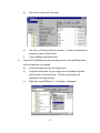
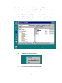
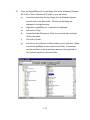
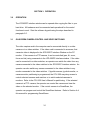
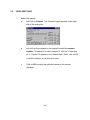
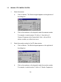
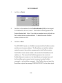
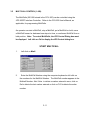
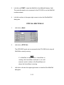
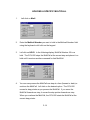
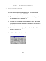
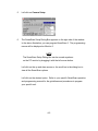
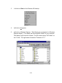
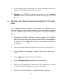
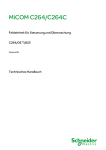
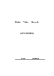
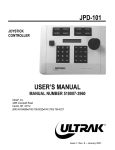
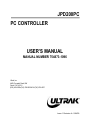
JPD200PC
PC CONTROLLER
USER’S MANUAL
MANUAL NUMBER 754873-1096
Ultrak, Inc.
4465 Coonpath Road, NW
Carroll, OH 43112
(800) 443-6680•(740) 756-9222•FAX (740) 756-4237
Issue 1 Revision A– 5/24/00
Issue 1 – March 2, 2000
Issue 1, Revision A – May 24, 2000 – added installation instructions for the video
capture card and windows setup instructions, added Figure 1-1.
©2000 By Ultrak®, Inc.
All Rights Reserved
Printed In The United States Of America
Ultrak, Incorporated
4465 Coonpath Road
Carroll, Ohio 43112
(740) 756-9222
Sales 1-800-443-6680 (Toll Free USA)
Technical Support 1-800-443-6681 (Toll Free USA)
ALL RIGHTS RESERVED. NO PART OF THIS PUBLICATION MAY BE REPRODUCED BY ANY MEANS WITHOUT WRITTEN
PERMISSION FROM ULTRAK®, INCORPORATED.
THE INFORMATION IN THIS PUBLICATION IS BELIEVED TO BE ACCURATE IN ALL RESPECTS. HOWEVER, ULTRAK,
INCORPORATED CANNOT ASSUME RESPONSIBILITY FOR ANY CONSEQUENCES RESULTING FROM THE USE THEREOF.
THE INFORMATION CONTAINED HEREIN IS SUBJECT TO CHANGE WITHOUT NOTICE. REVISIONS OR NEW EDITIONS TO
THIS PUBLICATION MAY BE ISSUED TO INCORPORATE SUCH CHANGES.
LICENSE AGREEMENT
End-User License Agreement (EULA) for Diamond Electronics’ JPD-200PC
Joystick Controller Interface for Microsoft Desktop Operating Systems.
SOFTWARE PRODUCT LICENSE
The SOFTWARE PRODUCT LICENSE, part number 754873-1197, is protected by copyright laws and
international copyright treaties, as well as other intellectual property laws and treaties. The SOFTWARE
PRODUCT is licensed, not sold. The term “COMPUTER” as used herein shall mean the hardware or the
computer system where the software resides and operates.
1.
GRANT OF LICENSE. This EULA grants you the following rights:
Software Installation and Use. You may only install and use one copy of the SOFTWARE
PRODUCT on the COMPUTER.
Back-up Copy. You may make a single back-up copy of the SOFTWARE PRODUCT . You may
use the back-up copy solely for archival purposes.
Rental. You may not rent or lease the SOFTWARE PRODUCT.
Termination. Without prejudice to any other rights, Diamond Electronics may terminate this
EULA if you fail to comply with the terms and conditions of this EULA. In such event, you must
destroy all copies of the SOFTWARE PRODUCT and all of its component parts.
2.
COPYRIGHT. All title and copyrights in and to the SOFTWARE PRODUCT (including but not
limited to any images, photographs, animations, video, audio, music, text, and “applets,”
incorporated into the SOTWARE PRODUCT), the accompanying printed materials, and any
copies of the SOFTWARE PRODUCT, are owned by Diamond Electronics, Inc., An Ultrak
Company. You may not copy the printed materials accompanying the SOFTWARE PRODUCT.
All rights not specifically granted under this EULA are reserved by Diamond Electronics, Inc.
3.
DUAL-MEDIA SOFTWARE PRODUCT. You may receive the SOFTWARE PRODUCT in more
than one medium. Regardless of the type or size of medium you receive, you may use only one
medium that is appropriate for the COMPUTER. You may not use or install the other medium on
another computer. You may not loan, rent, lease, or otherwise transfer the other medium to
another user, except as part of the permanent transfer (as provided above) of the SOFTWARE
PRODUCT.
TABLE OF CONTENTS
Page
SECTION 1. GETTING STARTED..............................................................................1-1
1.1 DESCRIPTION ..................................................................................................1-1
1.2 HARDWARE SETUP .........................................................................................1-1
1.3 INSTALLING THE SOFTWARE ........................................................................1-5
1.4 DEFINITIONS OF TERMS...............................................................................1-11
1.5 OPERATION....................................................................................................1-12
1.6 SPECIFICATIONS...........................................................................................1-14
SECTION 2. SETUP....................................................................................................2-1
2.0 SOFTWARE STARTUP.....................................................................................2-1
2.1 COMMUNICATION SETTINGS.........................................................................2-1
2.2 JPD-200PC ADDRESSING ...............................................................................2-2
2.3 COLOR ADJUSTMENTS...................................................................................2-3
2.4 CAMERA AND MONITOR SETUP ....................................................................2-4
2.5 DEFINING THE MONITOR NUMBER FOR THE JPD-200PC VIDEO
WINDOW ...........................................................................................................2-8
SECTION 3. OPERATION ..........................................................................................3-1
3.0 OPERATION......................................................................................................3-1
3.1 ON-SCREEN CAMERA CONTROL AND VIDEO SWITCHING ........................3-1
3.2 VIDEO SWITCHING ..........................................................................................3-1
3.3 MANUAL PTZ CAMERA CONTROL .................................................................3-4
3.4 SMARTSCAN CONTROL..................................................................................3-7
3.5 MULTICALL CONTROL (1-999). .....................................................................3-11
3.6 AUXILIARY CONTACT OUTPUT CONTROL (ON/OFF).................................3-15
3.7 ALARM CONTROL ..........................................................................................3-17
3.8 JPD FUNCTIONS F1 THROUGH F8...............................................................3-18
SECTION 4. PROGRAMMING SMARTSCANS .........................................................4-1
4.1 PROGRAMMING REQUIREMENTS .................................................................4-1
i
TABLE OF CONTENTS (CONT)
Page
SECTION 5. MAINTENANCE .....................................................................................5-1
5.1 MAINTENANCE PROCEDURES ......................................................................5-1
5.2 BACKING UP THE VSM-200 DATABASES TO DISKETTE..............................5-1
5.3 RESTORING THE JPD200PC DATABASES FROM DISKETTE TO THE
HARD DRIVE.....................................................................................................5-4
5.4 TROUBLESHOOTING GUIDELINES ................................................................5-5
ii
SECTION 1. GETTING STARTED
1.1
DESCRIPTION
The JPD-200PC Controller is a software application for PCs running a Windows
95, 98, or NT operating system. The PC must contain a Flashbus #MVLite video
capture card, Ultrak part number 840814-0242, and a serial port (COM 1) for
connection to a CCU-200 Communications Control Unit. An RS-232 to RS-485
Converter, (i.e. Ultrak part number 675498-C) is required for communication
between the PC and the CCU-200 Communications Control Unit. A mouse and
a keyboard are required for programming and controlling the software.
The JPD-200PC software running on the PC communicates with the CCU-200
Communications Control Unit to provide an on-screen window for viewing video
from a selected camera and controlling Ultrak’s CCU-200, domes, and switchers.
An operator can also acknowledge alarm inputs and control (on or off) contact
outputs. The alarm inputs and contact outputs must be connected to the CCU200.
1.2
HARDWARE SETUP
1)
Install the video capture card in the PC. This step may be done at the
factory if the PC and video capture card are purchased from Ultrak.
a.
If installing the card in a new computer, you must register your
operating system software. Start up the computer and register the
Windows 95/98 operating system to your company.
b.
Shut down the computer and remove power to the computer.
c.
Ground yourself by touching a grounded surface or use a static
protection device such as a grounded wrist strap.
d.
Remove the cover on the computer.
e.
Install the video capture card into one of the PCI slots. Refer to your
computer manuals and the user’s guide provided with the video
capture card for installation information.
1-1
f.
g.
h.
Restart the computer. Windows will detect the presence of a new
hardware board and ask for the location of the driver.
1.
Place disk 1 of the Flashbus MV setup files into Drive A.
Windows will find and install the driver for the Flashbus MV
video capture card.
Restart the computer and open the FBG.ini file (using notepad or
wordpad) in the Windows folder.
1. Change ONSCREEN=0 to ONSCREEN=1
Select true color (32-bit) mode in display properties.
a. Windows Start menu
b. Select Settings
c.
d.
e.
i.
Select Control Panel
Select Display
Select Settings Tab
Change the Color Palette to True Color
Define the properties for the Flashbus driver
Windows 95/98
1.
2.
3.
4.
5.
6.
7.
8.
Windows Start Menu
Select Settings
Select Control Panel
Select Multimedia
Select Advanced
Select Expand Media Control Devices and select Flashbus MCI
driver
Select Properties
Select Settings
Make the following selections:
Standard
- NTSC
Type
- Comp
Source
- Source 1
Flashtype
- None
FlashDelay
-1
Grab Align
- odd
Field Replication - None
1-2
Video Control
- Clip on overlap
- Monitor Messages
- Live deactivated win
- Live deactivated app
Windows NT
1.
2.
3.
4.
5.
6.
7.
Windows NT Start Menu
Select Settings
Select Control Panel
Select Multimedia
Select Devices
Expand Media Control Devices and select Flashbus MCI driver
(NT)
Select Properties
Make the following selections:
Standard
- NTSC
Type
- Comp
Source
- Source 1
Flashtype
- None
FlashDelay
-1
Grab Align
- odd
Field Replication - None
Video Control
- Clip on overlap
- Monitor Messages
- Live deactivated win
- Live deactivated app
NOTE
If the VGA video card and the FlashBus video
capture card are not compatible, consult
Integral Technologies’ Customer Support.
Refer to the FlashBus user’s guide for contact
information. Ultrak has been successful using
an ATI 3D Rage or Matrox Video Card.
1-3
2)
Connect COM1 (RS-232 serial port) on the PC to the RS-232 to RS-485
converter. Connect the RS-232 to RS-485 adapter to one of the RS-485
ports (CH1 through CH8) on the CCU-200. Refer to Figure 1-1.
CCU-200
COMMUNICATIONS CONTROL UNIT
PERSONAL
COMPUTER
RS-485/RS-232CONVERTER
Figure 1-1. INSTALLATION BLOCK DIAGRAM
The CCU-200 RS-485 port must be defined in the CCU-200 port setup
menu as a joystick controller port. Refer to the port setup programming
procedures in the CCU-200 User’s Manual.
The JPD-200PC must be given a unique device number and an address (18). The device number is defined in the CCU-200 Device Setup Menu. The
operator defines the JPD-200PC address using an on-screen menu on the
PC. Refer to paragraph 2.2 in Section 2 of this manual. Each CCU-200
RS-485 port can support up to eight (8) controllers. A maximum of 32
controllers can be connected to the CCU-200. The controllers connected
to the same port must be given unique addresses (1-8).
3)
Connect the video capture card in the PC to a camera for viewing a single
camera or to a video switcher for viewing multiple cameras. If you connect
the video capture card to a video switcher, you will need to know the video
output number you are connecting it to. Refer to paragraph 2.5 in Section
2 of this manual for identifying the video capture card when connected to a
switcher.
1-4
The communication between the PC and the CCU-200 is setup using the COM1
settings dialog box in the JPD-200PC interface and the port setup menu in the
CCU-200. The settings must be the same for both units.
Standard communications settings:
19.2K baud rate
1 stop bit
8 data bits
Even parity
Refer to paragraph 2.1 in Section 2 of this manual for setting the communication
for the PC. Refer to the CCU-200 User’s manual for setting the communication
for the CCU-200.
1.3
INSTALLING THE JPD200PC SOFTWARE
There are two files on the floppy disk that must be copied to your hard drive.
Use Windows Explorer to copy the files from the 3-1/2” floppy drive (e.g. A:) to
your hard drive (e.g. C:).
1)
Create a directory on your hard drive for the JPD200PC software.
a)
Open Windows Explorer. Explorer displays two windows – the left
window displays the drives on your computer. The right window
displays the files on the drives. Below is an example – your
windows will display the folders and files specific to your computer.
1-5
b)
Locate the drive letter for your hard drive (e.g. C:) and left click on
the drive letter to highlight it. The contents of your hard drive are
displayed in the right window.
c)
Left click on File in the main menu.
1-6
d)
Left click on New in the File menu.
e)
Left click on Folder in the New submenu. A folder is created with a
temporary name of New Folder.
f)
2)
Type Jpd200pc and press Enter.
Copy the file Jpd200pc.exe from the floppy drive to the Jpd200pc folder
on your hard drive you created.
a)
Insert the floppy disk into your floppy drive.
b)
Locate the drive letter for your floppy drive in Windows Explorer
and left click on the drive letter. The files on the floppy are
displayed in the right window.
c)
Right click on Jpd200pc.exe. A submenu is displayed.
1-7
d)
Left click on Copy.
e)
Locate the jpd200pc folder on your hard drive and right click on the
folder.
f)
Left click on Paste.
g)
Left click on the Jpd200pc folder on your hard drive. Make sure the
file Jpd200pc.exe was copied to the folder. It should appear in the
right window (e.g. Contents of ‘D:\’).
1-8
h)
Create a shortcut on your desktop for the jpd200pc software.
1)
If necessary, resize the Windows Explorer window so you
can view part of your Windows desk top.
2)
Right click on jpd200pc.exe and hold the right mouse button.
3)
While holding the right mouse button, drag the file to your
desktop.
4)
Release the mouse button.
5)
Left click on Create Shortcut(s) Here.
1-9
4)
Copy the file jpd200pc.ini from the floppy drive to the Windows (Windows
95 or 98) or Winnt (Windows NT) folder on your hard drive.
a)
Locate the drive letter for your floppy drive in Windows Explorer
and left click on the drive letter. The files on the floppy are
displayed in the right window.
c)
Right click on jpd200pc.ini. A submenu is displayed.
d)
Left click on Copy.
e)
Locate the folder Windows or Winnt on your hard drive and right
click on the folder.
f)
Left click on Paste.
g)
Left click on the Windows or Winnt folder on your hard drive. Make
sure the file jpd200pc.ini was copied to the folder. If necessary,
use the scroll bar or the up and down arrows on the right side of
the Contents window to view more files.
1-10
1.4
DEFINITIONS OF TERMS
The following terms are used throughout this manual. Please become familiar
with them before programming or controlling the SmartScan units or controlling
the CCU-200 Communications Control Unit. Refer to the specific Operation and
Programming Manual for programming procedures for the SmartScan units and
the CCU-200 Communications Control Unit.
SmartScan
A programmable video device containing a camera, lens, pan and tilt, a digital
receiver board, and a power supply. There are several different models –
SmartScan, SmartScan Pro II, SmartScan III Series, or KD6 UltraDome. A
SmartScan is often referred to as a scan. The SmartScan device enclosed in its
housing is often referred to as a dome.
PreShot
A PreShot is a camera/lens position including pan, tilt, zoom, and focus that can
be given a title and stored in a SmartScan. The number of characters allowed in
the title (either 16 or 24) is dependent on the character generator on the unit. Up
to 100 (00-99) PreShots can be programmed and stored in each SmartScan unit.
PreShots can be programmed from the JPD-200PC Interface.
An operator can send a SmartScan to a programmed PreShot using the JPD200PC interface. When the SmartScan is viewing the PreShot, the title of the
PreShot is added to the video signal.
VectorScan
A VectorScan can be considered a video tour. It is two or more PreShots (up to
64) from the same scan unit linked together with specified dwell times. Up to ten
(0-9) VectorScans can be stored in each SmartScan. The VectorScan title can
be up to 16 or 24 characters depending on the character generator on the
SmartScan. VectorScans can be programmed using the JPD-200PC Interface.
VectorScans can be started or stopped using the JPD-200PC Interface. When a
1-11
VectorScan is running in a SmartScan, the title of the PreShot currently being
viewed is added to the SmartScan video signal.
Sector ID
Sector ID's are used for labeling specific areas that the scan views. Up to 16
Sector IDs can be programmed and stored in each SmartScan. The Sector ID
title can be up to 16 or 24 characters depending on the character generator on
the SmartScan. Sector ID's can be programmed using the JPD-200PC
Interface. Whenever the dome is under manual control and viewing a
programmed sector, the title of the sector is added to the SmartScan video
signal.
MultiCall
A MultiCall can be programmed to perform one or more system functions at the
same time or in series with programmable dwell times between each function.
The system functions that can be included in a MultiCall are PreShots,
VectorScans, video switching, turning on/off VCR's or other auxiliary devices, or
starting a MultiCall (including itself). MultiCalls are used to define the system's
response to events such as date/time, alarms, and JPD-200PC Interface
function keys (F1 through F8). A MultiCall can also be used to sequence
cameras on a monitor. Up to 999 (001-999) MultiCalls can be programmed and
stored with a 16-character title in the CCU-200 Communications Control Unit.
MultiCalls are programmed using a VSM-200 Video System Manager or a CCU200 Communications Control Unit. A MultiCall can be started, stopped, placed
on hold, or controlled one step at a time through the JPD-200PC Interface.
1.5
OPERATION
The JPD-200PC is capable of calling up 999 cameras to 999 monitors for
manual control (pan, tilt, zoom, focus, and iris) and viewing purposes. The JPD200PC can be used to program PreShots, VectorScans, and Sector IDs. The
on-screen setup features of a SmartScan can also be defined using the JPD200PC. Listings of the programmed PreShots, VectorScans, VectorScan
1-12
Contents, and Sector IDs can also be called-up from the JPD-200PC. These
listings are for viewing purposes only; they cannot be edited. Editing must be
done in the programming mode.
The JPD-200PC can be used to acknowledge alarms. Up to 256 alarms are
available with AIU-100 Alarm Interface Units connected to the CCU-200. The
oldest alarm or all alarms can be acknowledged.
An operator can control auxiliary devices (on or off) using the JPD-200PC. The
operator must know the physical address setting of the auxiliary device and the
contact output number (port number) on the device.
The JPD-200PC has eight programmable function (quick) keys. The function
keys are programmed by programming the desired MultiCall for each key, then
assigning the MultiCalls to the function keys. The programming and assignment
of the MultiCalls is performed at the CCU-200 Communications Control Unit.
The function keys are designed to perform a single system action or many
system actions using a single keystroke.
The actions can be initiated
simultaneously or in a series with dwell times (up to 99 seconds) between each
action. The actions that can be programmed for a function key are PreShots,
VectorScans, Video Switching, Auxiliary Control (VCR's), MultiCalls,
acknowledge oldest alarm, acknowledge all alarms, acknowledge a specific
alarm, enable alarm, enable all alarms, disable alarm, disable all alarms, and
halt all MultiCalls. Selecting the function key once starts the assigned MultiCall.
Selecting the function key again (before the MultiCall finishes) stops the
assigned MultiCall. If the MultiCall has completed, selecting the function key
again restarts the MultiCall.
1-13
1.6
SPECIFICATIONS
Operating System:
Communication:
Baud Rate:
Windows 95/98/NT
RS-232
One Start Bit, One Stop Bit, 8 Data Bytes, Even
Parity
19.2K Baud
1-14
SECTION 2. SETUP
2.0
SOFTWARE STARTUP
To open the JPD200PC Controller software, double click (using the left
mouse button) on the JPD200pc icon on your desktop. If you did not
create a shortcut on your desktop as described in paragraph 1.3.2.h in
Section 1 of this manual, you can start the software from Windows
Explorer.
1)
Open Windows Explorer.
2)
Locate the JPD200pc folder on your hard driver and click on the
folder. Double click (left mouse button) on the file jpd200pc.exe in
the contents window.
2.1
COMMUNICATION SETTINGS
COM1 on the PC is connected to one of the CCU-200 RS-485 ports. The
baud rate, data bits, parity, and stop bit settings must be the same for
both components. The default settings are:
19.2K Baud
8 Data Bits
Even Parity
1 Stop Bit
2-1
To change the communication settings:
1)
Click on Settings
2)
Position the mouse cursor on Com1 to open the pull-down menu.
3)
Position the mouse cursor on the setting you need to change.
4)
Select the desired setting from the pull-down menu.
5)
Repeat steps 1 through 4 until the desired communications settings
are defined.
2.2
JPD-200PC ADDRESSING
All JPD-200PC Controllers must be given an address (1-8). The JPD-200
Controllers connected to the same port on the CCU-200 Communication
Control Unit must have unique addresses. The address of the JPD200PC is set using an on-screen menu.
1.
Point to Setup and click the left mouse button.
2-2
2.
Point to JPD Address (1-8) and click the left mouse button.
3.
The current address is displayed in the box. Select a different
address by scrolling up or down until the desired number is
displayed in the box. Click on OK to save the number displayed.
Click on Cancel to close the dialog box without changing the JPD
address.
2.3
COLOR ADJUSTMENTS
The color in the video window can be adjusted for the desired brightness,
saturation, contrast, and hue.
1.
Click on setup.
2-3
2.
Click on Color Adjust.
3.
Use the left and right arrows or the scroll bars to adjust the video
brightness, saturation, contrast, and hue to the desired levels.
4.
Click on the X in the upper right corner to close the dialog box and
save the settings.
2.4
CAMERA AND MONITOR SETUP
Each camera in the system can be given a description and the camera
can be defined as a Fixed camera, a PTZ (pan, tilt, zoom), or a TeleCam.
Each monitor in the system can be given a description.
1.
Select the camera you want to setup.
a.
Click on Camera. A keypad appears on the right side of the
window.
2-4
b.
Click on ADV to configure the camera.
c.
Select a camera from the list by clicking on the camera
number to highlight the number. Use the up and down
arrows or the scroll bar to view more camera numbers.
1.
Click on Configure. The selected camera number
appears in the Camera field.
2.
Type a description or location for the camera number
displayed. If a description is already displayed, you
can keep the same description or change it.
3.
Click on the type of camera (Fixed or PTZ). Note:
Any camera device that can be positioned (i.e.
SmartScan) is a PTZ.
2-5
4.
Click on OK to close the dialog box and save your
changes. Click on Cancel to close the dialog box
without saving any changes. The Select
Camera/Monitor dialog box returns to the display.
d.
All the cameras can be configured at one time. Select
another camera by highlighting the number and left clicking
on Configure. Note: the monitors can also be configured
from this dialog box.
e.
To close the dialog box, click on the X in the upper right
corner of the Select Camera/Monitor Dialog Box.
2.
To configure the monitors, click on Monitor. A Monitor keypad
appears on the right side of the dialog box.
a.
Click on ADV to configure the monitors. The Select
Camera/Monitor dialog box opens.
2-6
b.
Select a monitor by clicking on the monitor number. Use the
up and down arrows or the scroll bar to move up and down
to view more monitor numbers.
c.
Click on Configure. The selected monitor number appears
in the Monitor field.
d.
Type in a Description for the monitor.
e.
Click on OK to close the dialog box and save the description
or click on Cancel to close the dialog box without saving the
description. The Select Camera/Monitor dialog box returns.
f.
All the monitors can be configured at one time. Select
another monitor by highlighting the number and click on
Configure. Note: The cameras can also be configured from
this dialog box.
g.
To close the dialog box, click on the X in the upper right
corner of the Select Camera/Monitor Dialog Box.
2-7
2.5
DEFINING THE MONITOR NUMBER FOR THE JPD-200PC VIDEO
WINDOW
If the video capture card is connected directly to a camera, the monitor
number is 1. If the video capture card is connected to a video switcher,
you must define the monitor number for the JPD-200PC Video Window.
You must know the video switcher output number the video capture card
is connected to. Note: the default setting is 1. If the video capture card is
connected to video switcher output 1, you do not need to change it.
1.
Point to Setup and click the left mouse button.
2.
Point to System Monitor and click the left mouse button.
2-8
3.
Select the video output number the video capture card is
connected to by pointing to the video output number and clicking the
left mouse button. The monitor number is highlighted when it is
selected. If the number is not displayed, use the scroll bar or the up
and down arrows to the right of the monitor numbers to view more
numbers. Click on OK to close the dialog box and save your
selection. To close the dialog box without saving changes, click on
Cancel.
2-9
This page left blank intentionally.
2-10
SECTION 3. OPERATION
3.0
OPERATION
The JPD200PC interface window can be opened after copying the files to your
hard drive. All hardware must be connected and operational for the control
functions to work. Start the software by performing the steps described in
paragraph 2.0.
3.1
ON-SCREEN CAMERA CONTROL AND VIDEO SWITCHING
The video capture card in the computer can be connected directly to a video
camera or to a video switcher. If the video card is connected to a camera, that
camera’s video is displayed in the JPD-200PC Interface Window on the PC
monitor. If the camera is a PTZ camera, it can be controlled (pan, tilt, zoom,
focus and iris) using commands in the JPD-200PC Interface window. If the video
card is connected to a video switcher, an operator can switch the video from any
camera connected to the video switcher to the JPD-200PC Interface window. An
operator can also switch any camera connected to the video switcher to any
monitor connected to the video switcher. If joystick-camera, joystick-monitor, or
camera-monitor partitioning is programmed, the CCU-200 may deny access to
control selected cameras and monitors or to switch selected cameras to
monitors. Refer to the CCU-200 User’s Manual for partitioning. If the selected
camera is a PTZ camera, the operator can control the camera and view the
video on the selected monitor. If the control camera is a SmartScan, the
operator can program and control the SmartScan features. Refer to Section 4 of
this manual for programming SmartScans.
3-1
3.2
VIDEO SWITCHING
1.
Select the camera.
a.
Left click on Camera. The Camera keypad appears on the right
side of the dialog box.
b.
Left click on the numbers on the keypad to select the camera
number. For example, to select camera 12, click on 1; then click
on 2. Camera 12 appears in the Camera field. Note: click on Del
to delete a number you clicked on in error.
c.
Click on OK to switch the selected camera to the monitor
displayed.
3-2
2.
Select the monitor number.
a.
Left click on Monitor. The Monitor keypad appears on the right
side of the dialog box.
b.
Left click on the numbers on the keypad to select the monitor
number. For example, to select monitor 5, click on 5. Monitor 5
appears in the Monitor field. Note: click on Del to delete a number
you clicked on in error.
c.
Click on OK to switch the camera displayed to the selected
monitor.
NOTE
If you click on ADV from either the Monitor
keypad or the Camera Keypad, you can
perform video switching by highlighting a
camera and a monitor in the Select
Camera/Monitor dialog box.
3-3
3.3
MANUAL PTZ CAMERA CONTROL
1.
Select the camera.
a.
Click on camera. The Camera keypad appears on the right side of
the dialog box.
b.
Click on the numbers on the keypad to select the camera number.
For example, to select camera 12, click on 1; then click on 2.
Camera 12 appears in the Camera field. Note: click on Del to
delete a number you clicked on in error.
2.
Select the monitor number for the PC video window.
a.
Click on Monitor. The Monitor keypad appears on the right side of
the dialog box.
b.
Click on the numbers on the keypad to select the monitor number.
For example, to select monitor 5, click on 5. Monitor 5 appears in
3-4
the Monitor field. Note: click on Del to delete a number you clicked
on in error.
3.
Click on Ctrl. The JPD Control box opens on the right side of the dialog
box. The PC sends all commands out with the camera address shown in
the Camera field.
Pan and Tilt
Position the mouse in the video window. A cross hair representing pan
and tilt is displayed in the video window.
Hold the left mouse button
down and move the mouse up and down in the video window to reposition
the tilt; hold the left mouse button down and move the mouse left and right
in the video window to reposition the pan.
Focus
The camera lens focus functions are operational upon power-up of the
unit. Click on focus far or focus near to change the focus setting for the
selected camera.
Zoom
Change the lens zoom setting by clicking on zoom in or zoom out. The
lens zoom in or out can be controlled one increment at a time by clicking
3-5
and releasing the left mouse button or you can continuously press the left
mouse button until the desired setting is achieved.
Iris
The iris function is set for automatic operation upon power-up of the
system. To control the iris, the iris selection must be set for manual
operation.
Manual Iris Control
Left click on the Iris button.
NOTE
You can move the Iris Control Box anywhere
on the PC monitor by dragging it with the
mouse. Position the mouse cursor on Iris
Control, hold the left mouse button down and
move the box to the desired location, then
release the left mouse button.
In the above dialog box, Auto Iris is selected. To switch to Manual Iris, point
to the box beside Manual and click the left mouse button. To revert to auto
iris, point to the box beside Auto and click the left mouse button.
When Manual iris is selected, you can control the lens iris by pointing to
Open or Close and clicking the left mouse button. The iris can be controlled
3-6
one increment at a time by clicking and releasing the left mouse button or
you can continuously hold down the left mouse button until the desired iris
setting is achieved.
The Iris Control dialog box can be left open and another control selected, or
the Iris Control dialog box can be closed. If you close the dialog box, the
lens iris returns to the automatic mode.
3.4
SMARTSCAN CONTROL
SmartScan control includes PreShots and VectorScans. To send a SmartScan
to a PreShot or start a VectorScan, the JPD-100PC must have manual control of
the SmartScan unit and the JPD Control dialog box must be displayed. Left click
on Ctrl to display the JPD Control dialog box.
3-7
GO TO PRESHOT
1.
Left click on Pshot.
2.
Left click on the numbers for the PreShot Number (0-99) on the keypad.
For PreShot 25, click on 2, then 5. The PreShot number appears in the
Preshot Number field. Note: If you click on a number in error, left click on
Del to delete the last number selected. To delete the entire PreShot
number, left click on CLR.
3.
Left click on Run.
The JPD-200PC sends out a PreShot command with the PreShot number
and the control camera address. The SmartScan unit with that address
sends the scan to the positions programmed for that PreShot number.
The PreShot scene can be viewed on the monitor the SmartScan unit is
called up on. The name of the PreShot appears on the monitor (if
PreShot Names is turned on in the SmartScan) and remains there until
the SmartScan gets a manual control command, another PreShot
command, or a VectorScan command. If the PreShot does not exist, the
SmartScan outputs the message 'DOES NOT EXIST' on the video signal.
3-8
4.
You can continue to send the SmartScan to different PreShots or exit the
Run PreShot Dialog box by clicking on the x in the right upper corner of the
dialog box.
RUN VECTORSCAN
1.
Left click on Vscan.
2.
Left click on the number (0-9) for the VectorScan Number on the keypad.
For VectorScan 2, click on 2. The VectorScan number appears in the
VectorScan Number field. Note: If you click on a number in error, left
click on Del to delete the number selected.
3.
Left click on Run.
The JPD-200PC sends out the VectorScan command with the VectorScan
number and the control camera address. The SmartScan unit with that
address starts the VectorScan programmed for the VectorScan number.
The SmartScan goes to the first PreShot listed in the VectorScan and
remains there for the specified dwell time. The PreShot name is
displayed on the monitor if PreShot Names is enabled. The SmartScan
unit goes to the next PreShot in the list and remains there for the specified
dwell time. The PreShot name is displayed on the monitor. The
3-9
SmartScan unit continues to go to the next PreShot and outputs the
PreShot name until it reaches the end of the listing; then it starts over
again with the first PreShot in the listing.
STOP VECTORSCAN
Once started, a VectorScan continues to run until stopped by an operator. To
stop a VectorScan, the SmartScan unit running the VectorScan must be the
control camera displayed on the JPD-200PC Controller. Manually control (pan,
tilt, zoom, focus, iris) the SmartScan, send the SmartScan to a PreShot, or start
a different VectorScan.
3-10
3.5
MULTICALL CONTROL (1-999).
The MultiCalls (001-999 stored in the CCU-200) can be controlled using the
JPD-200PC Interface Controller. Refer to the CCU-200 User’s Manual, as
applicable, for programming MultiCalls.
An operator can start a MultiCall, stop a MultiCall, put a MultiCall on hold, move
a MultiCall forward or backward one step at a time, or continue a MultiCall from a
held position. Note: To control MultiCalls, the JPD Control Dialog box must
be displayed. Left click on Ctrl to display the JPD Control dialog box.
START MULTICALL
1.
Left click on Mcall.
2.
Enter the MultiCall Number using the computer keyboard or left click on
the numbers for the MultiCall Number. The MultiCall number appears in the
Multicall Number: field. Note: to delete a number entered in error, click on
Del to delete the last number entered or click on CLR to delete the entire
number.
3-11
3.
Left click on START to start the MultiCall in the Multicall Number: field.
The controller sends out a command to the CCU-200 to run the MultiCall
number entered.
4.
Left click on the x in the upper right corner to close the Run MultiCall
dialog box.
STOP ALL MULTICALLS
1.
Left click on Mcall.
2.
Left click on STOP ALL.
The JPD-200/P sends out a command to the CCU-200 Unit to stop all
MultiCalls currently running.
NOTE
If a MultiCall is halted while a VectorScan is
running, the VectorScan continues to run until
manual control is taken at the SmartScan unit
where the VectorScan is running.
3.
Left click on the x in the upper right corner to close the Run MultiCall
dialog box.
3-12
STOPPING A SPECIFIC MULTICALL
1.
2.
Left click on Mcall.
Enter the Multicall Number you want to stop in the Multicall Number: field
using the keyboard or left click on the keypad.
3.
Left click on STOP. The JPD-200PC Interface sends a command to the
CCU-200 to stop the MultiCall number entered.
4.
Left click on the x in the upper right corner to close the Run MultiCall
dialog box.
3-13
HOLDING A SPECIFIC MULTICALL
1.
2.
Left click on Mcall.
Enter the Multicall Number you want to hold in the Multicall Number: field
using the keyboard or left click on the keypad.
3.
Left click on HOLD. In the following display, MultiCall Number 25 is on
hold. The CCU-200 stops the MultiCall at the current step and places it on
hold until it receives another command for that MultiCall.
4.
You can now process the MultiCall one step at a time (forward or back) or
continue the MultiCall. Left click on the desired option. The CCU-200
moves its step pointer as you process the MultiCall. If you move the
MultiCall forward one step, it moves the step pointer forward one step.
When you continue the MultiCall, the CCU-200 starts the MultiCall at the
current step pointer.
3-14
5.
Left click on the x in the upper right corner to close the Run MultiCall
dialog box.
3.6
AUXILIARY CONTACT OUTPUT CONTROL (ON/OFF).
The JPD-200PC can send control data out to turn auxiliary devices on or off.
The CAT Video Switcher, the CRX-800 Series Control Receivers, the CRX-500
Series Control Receivers, and the AIF-100/CO Contact Output Units have
contact outputs for connection to VCR's, flood lights, etc. The CRX-800
Receivers and the AIF-100/CO units are addressable. The contacts are
controlled by sending an ON message for a specific contact to the unit address
or an OFF message for a specific contact to the unit address. If the contact
output is configured as normally open, an ON message closes the contact and
an OFF message opens the contact. If the contact output is configured as
normally closed, an ON message opens the contact and an OFF message
closes the contact.
To control a contact output, the address of the unit (where the contact output is
located) must be the control camera on the JPD-200PC. To control the contact
outputs on the CAT Video Switcher, the control camera must be camera 1.
Note: A CRX-800 Receiver or an AIF-100/CO Contact Output Device cannot be
addressed one (1) if a CAT Video Switcher is installed in the system and the
system requires control of the contact outputs.
3-15
AUXILIARY CONTROL
The JPD Control Dialog Box must be displayed (Left click on Ctrl next to the
Camera field).
1.
Enter the address of the contact output device in the Camera field.
2.
Left click on Aux in the JPD Control Dialog Box.
3.
Left click on the numerical keypad to enter the auxiliary contact output
number in the Aux Port Number field. Left click on the Del key to delete any
number clicked on in error or left click on the CLR key to clear the field.
4.
Left click on ON or OFF to control the auxiliary device.
5.
Point to the x in the upper right corner to close the Aux control dialog box.
3-16
3.7
ALARM CONTROL
A CCU-200 Communications Control Unit supports programming features for
handling alarm inputs. Refer to your CCU-200 user’s manuals for alarm
programming and operation. An operator can acknowledge the oldest alarm or
all alarms present in the system at the JPD-200PC Interface Controller.
The JPD Control dialog box must be displayed (Left click on Ctrl beside the
Camera field).
1.
Left click on Alarm.
2.
Left click on Acknowledge Oldest or Acknowledge All.
3.
Continue acknowledging alarms or left click on the x in the upper right
corner to close the dialog box.
3-17
3.8
JPD FUNCTIONS F1 THROUGH F8
Function keys F1 through F8 are programmed by programming a MultiCall, then
assigning the MultiCall to the function key. All programming is stored in the
CCU-200 Communication Control Unit. Refer to the CCU-200 User’s Manual for
programming MultiCalls and assigning MultiCalls. MultiCalls are assigned to the
JPD’s function keys using the CCU-200 Device Setup Menu.
The function keys are designed to perform a single system action or many
system actions using a single keystroke. The actions can be initiated
simultaneously or in a series with dwell times (up to 99 seconds) between each
action. The actions that can be programmed for a function key are PreShots,
VectorScans, video switching, auxiliary control (video recording), MultiCalls, and
alarm control. Clicking on the function key once starts the assigned MultiCall. If
the MultiCall is still processing, clicking on the function key again stops the
assigned MultiCall. If the MultiCall has completed processing, clicking on the
function key again restarts the MultiCall. If the key is not programmed, nothing
happens when you click on the function key.
3-18
NOTE
If a VectorScan is started in a MultiCall and the
MultiCall is stopped with the VectorScan
running, the VectorScan continues to run until
manual control of the camera is taken.
Pressing the function key again does not halt a
VectorScan.
Each function key can be given a title or description. When you position the
mouse cursor on the function key, the description is displayed below the function
keys as shown below.
1)
Right click on the function key.
2)
Enter a description for the Function Key such as the MultiCall number
assigned to it or the device(s) the function key controls.
3)
Left click on OK to accept the description.
3-19
This page left blank intentionally!
3-20
SECTION 4. PROGRAMMING SMARTSCANS
4.1
PROGRAMMING REQUIREMENTS
On-screen menus are used to program SmartScans. The SmartScan setup
menus can be accessed through the JPD-200PC Interface.
1.
The camera number you want to setup or program must be displayed in
the Camera field. Refer to paragraph 3.3
2.
The video from the SmartScan must be displayed on the PC video window.
The programming menus are generated by the SmartScan and outputted on
the video signal.
3.
You must have manual control (pan, tilt, etc.) of the SmartScan. Click on
Ctrl next to the camera field.
4.
Left click on Setup on the main menu bar.
4-1
5.
Left click on Camera Setup.
6.
The SmartScan Setup Dialog Box appears on the right side of the window.
In the above illustration, you can program SmartScan 5. The programming
menus will be displayed on Monitor 5.
NOTE
The SmartScan Setup Dialog Box can be moved anywhere
on the PC monitor by dragging it with the left mouse button.
Left click on the up and down arrows or the scroll bar in the dialog box to
view all the SmartScan options.
Left click on the desired option. Refer to your specific SmartScan operation
and programming manual for the guidelines and procedures to program
your specific unit.
4-2
SECTION 5. MAINTENANCE
5.1
MAINTENANCE PROCEDURES
Refer to the maintenance sections in the computer product manuals for detailed
information on maintaining the Pentium computer, monitor, and keyboard.
5.2
BACKING UP THE JPD-200PC DATABASES TO DISKETTE
Diamond Electronics recommends backing up the databases for the camera
configurations, monitor configurations, and user settings. This is a precaution in
case database files are deleted accidentally or in case of a hard drive failure.
The databases can be backed up while the JPD-200PC Interface is running.
Perform the following steps. For more detailed information using Windows 95 or
Windows NT software, refer to the on-screen help provided with your Windows
operating system.
1.
Obtain a blank, high-density 3.5” diskette. The disk does not have to be
formatted. Insert the diskette into the 3.5” floppy drive.
2.
Minimize the JPD-200PC main menu by left clicking on the
the upper right corner of the window.
5-1
symbol in
3.
Left click on Start on the Windows 95 desktop.
4.
Left click on Programs.
5.
Left click on Windows Explorer. The following is an example of a Windows
Explorer display. Your display will show specific folders for your computer.
The display is split into two screens: The left screen shows “All Folders” on
the C: drive. The right screen shows the “Contents of ‘C:\’”.
5-2
6.
7.
8.
Use the arrow bar to move down through the “All Folders” display until the
jpd200pc folder is displayed.
Point to the jpd200pc folder and double click the left mouse button. The
contents of the folder are displayed in the right window display. The right
screen display should change to “Contents of C:\jpd200pc”.
While holding down the CTRL key on the keyboard, point to each file with
an extension of .dat and click the left mouse button to backup the database
files. Observe that each filename becomes highlighted when clicked on.
NOTE
If you highlight a file you don’t want to backup,
continue holding down the CTRL key and point
to the file and click the left mouse button. The
highlight is removed from the file.
9.
Move the All Folders display up so the 3½ Floppy Drive A: can be viewed.
10.
Place the mouse pointer within the selected files, hold down the left mouse
button and drag the files up and drop them on the 3½ Floppy Drive A: by
pointing to the A: drive and releasing the left mouse button.
11.
If the diskette has not been formatted, Explorer will ask if you want to
format the disk now. Click on Yes and follow the dialog boxes as Explorer
performs a format on the floppy diskette.
After the disk is formatted,
Explorer will copy the files from the C: drive to the A: drive.
12.
While Explorer is copying the files, a message box displays the current file
being copied.
13.
When the copy procedure is complete, label the diskette with the date and
contents.
5-3
5.3
14.
Close Windows Explorer by pointing to the X in the upper right corner of the
Explorer Title Bar and click the left mouse button.
15.
Maximize the JPD200PC program by pointing to the minimized
JPD200PC Icon on the Windows 95 desktop and clicking the left mouse
button.
RESTORING THE JPD200PC DATABASES FROM DISKETTE TO THE HARD
DRIVE
If the databases become corrupted or are deleted, the databases can be
restored if a backup of the databases has been done as described in paragraph
5.2. The JPD200PC software must be shutdown prior to restoring the database
files.
1.
Shutdown the JPD200PC software by pointing to File on the JPD200PC
Main Menu Window and clicking the left mouse button or pressing Alt+F on
the keyboard. Point to Exit and click the left mouse button or press X on
the keyboard.
2.
Insert the diskette containing the database backup files in diskette drive A:.
3.
Point to Start on the Windows 95 desktop and click the left mouse
button.
4.
Point to Programs and click the left mouse button.
5.
Point to Windows Explorer and click the left mouse button.
6.
Point to the 3½ Floppy Drive A: and click the left mouse button. The files
on the floppy disk are displayed on the right screen display.
7.
Position the All Folders display so the jpd200pc folder is displayed.
5-4
8.
Copy the files on the floppy diskette to the jpd200pc folder.
a.
b.
c.
Highlight all the files on the floppy diskette.
Position the mouse cursor so it is located within the highlighted files.
Holding the left mouse button down, drag the files to the jpd200pc
folder and release the left mouse button.
9.
The JPD200PC databases have now been restored.
10.
Close Windows Explorer by pointing to the X in the far upper right corner
of the Explorer Title Bar and clicking the left mouse button. The screen
returns to the Windows 95 or Windows NT Desktop.
11.
5.4
Restart the JPD200PC software by pointing to the JPD200PC Icon and
double-clicking the left mouse button.
TROUBLESHOOTING GUIDELINES
If problems occur at the initial installation phase, ensure the equipment is
installed properly. Because this unit is just one part of an overall system, it may
be necessary to verify that the other equipment types have been installed and
are operating correctly before assuming the problem exists at the JPD200PC
Interface Controller.
Refer to the vendor product manuals for troubleshooting guidelines and
diagnostic tests for the computer.
5-5
If problems still exist after verifying correct installation and the problem has been
isolated to the JPD200PC software, contact the factory for technical support.
Ultrak®, Inc.
Service Department
4465 Coonpath Road
Carroll, Ohio 43112
(740) 756-9222
1-800-443-6680
5-6