1
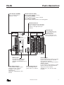
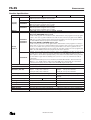
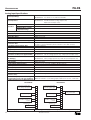
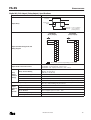
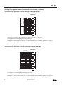
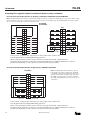
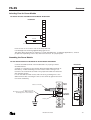
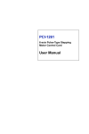
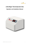
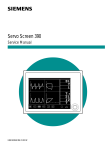
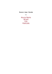
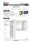
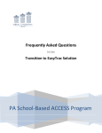
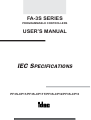
FA-3S SERIES
PROGRAMMABLE CONTROLLERS
USER’S MANUAL
IEC SPECIFICATIONS
PF3S-CP11/PF3S-CP11T/PF3S-CP12/PF3S-CP13
FA-3S
SAFETY PRECAUTIONS
• Read this user’s manual to make sure of correct operation before starting installation, wiring, operation, maintenance, and
inspection of the FA-3S programmable controllers.
• All FA-3S PLCs are manufactured under IDEC’s rigorous quality control system, but users must add a backup or failsafe
provision to the control system using the FA-3S in applications where heavy damage or personal injury may be caused in
case the FA-3S should fail.
• In this user’s manual, safety precautions are categorized in order of importance to Warning and Caution:
Warning
Warning notices are used to emphasize that improper operation may cause
severe personal injury or death.
Caution
Caution notices are used where inattention might cause personal injury or
damage to equipment.
Warning
• Turn power off to the FA-3S before starting installation, removal, wiring, maintenance, and inspection on the FA-3S. Failure to turn power off may cause electrical shocks or fire hazard.
• Special expertise is required to install, wire, program, and operate the FA-3S. People without such expertise must not use
the FA-3S.
• Emergency and interlocking circuits must be configured outside the FA-3S. If such a circuit is configured inside the FA-3S,
failure of the FA-3S may cause disorder of the control system, damage, or accidents.
Caution
• Install the FA-3S according to instructions described in this user’s manual. Improper installation will result in falling, failure, or malfunction of the FA-3S.
• FA-3S is designed for installation in equipment. Do not install the FA-3S outside of equipment.
• Install the FA-3S in environments described in this user’s manual. If the FA-3S is used in places where the FA-3S is subjected to high-temperature, high-humidity, condensation, corrosive gases, excessive vibrations, and excessive shocks, then
electrical shocks, fire hazard, or malfunction will result.
• The pollution degree of the FA-3S is “Pollution degree 2.” Use the FA-3S in environments of pollution degree 2 (according
to IEC664-1).
• All DC power type FA-3S units are “PS2” type (according to EN61131).
• Prevent the FA-3S from falling while moving or transporting the FA-3S, otherwise damage or malfunction of the FA-3S
will result.
• Prevent metal fragments and pieces of wire from dropping inside the FA-3S housing. Put a cover on the FA-3S during
installation and wiring. Ingress of such fragments and chips may cause fire hazard, damage, or malfunction.
• Use a power supply of the rated value. Use of a wrong power supply may cause fire hazard.
• Use wires of a proper size to meet voltage and current requirements. Tighten M3.5 terminal screws to a proper tightening
torque of 0.8 N-m.
• Use an IEC127-approved fuse on the power line outside the FA-3S. This is required when exporting equipment containing
FA-3S to Europe.
• Use an IEC127-approved fuse on the output circuit. This is required when exporting equipment containing FA-3S to
Europe.
• Use an EU-approved circuit breaker. This is required when exporting equipment containing FA-3S to Europe.
• Make sure of safety before starting and stopping the FA-3S or when operating the FA-3S to force outputs on or off. Incorrect operation on the FA-3S may cause machine damage or accidents.
• If relays or transistors in the FA-3S output circuit fail, outputs may remain on or off. For output signals which may cause
heavy accidents, provide a monitor circuit outside of the FA-3S.
• Do not connect to the ground directly from the FA-3S. Connect a protective ground to the equipment containing FA-3S
using an M4 or larger screw. This is required when exporting equipment containing FA-3S to Europe.
• Do not disassemble, repair, or modify the FA-3S.
• When disposing of the FA-3S, do so as an industrial waste. Dispose of the memory pack in accordance with pertaining regulations (memory packs PFA-1M21, PFA-1M24, and PFA-1M28 contain a battery).
IEC SPECIFICATIONS
1
TABLE
2
OF
FA-3S
CONTENTS
Object
IEC 1131-2 Subclause
See Page in IEC Specifications Manual
Total response time(s) formula
4.2.3
User’s Manual EM267 pages A-7 to A-11
Equipment ambient temperature limits
Note 3 of 2.1.1.1
5
Relative humidity
2.1.1.3
5
Pollution degree
2.1.1.4
5
Corrosion protection
2.1.1.5
User’s Manual EM267 page 2-1
Electrostatic discharge severity level
2.1.2.2
11
Vibrations
2.1.3.1
5
Special transport and storage conditions
2.3
5
Transport and storage
2.3.6
5
Sizing of a dedicated power source
Note 3 of 3.2.1.1
4 and 5
Non-standard power supplies
Note 5 of 3.2.1.1
4
Power supply
3.2.3
4 and 5
Additional external load
Item 4 of 3.3
12 to 14
A.C. inputs fed from several phases
Item 5 of 3.3
13
Non-standard digital I/Os
Note 2 of 3.3
12, 13, 15 to 17
Digital inputs
3.3.1.4
12 and 13
Protected/non-protected outputs
3.3.2.2
15 and 16
Short-circuit proof outputs
3.3.2.2
15 and 16
A.C. digital outputs
3.3.2.3
15
D.C. digital outputs
3.3.3.3
15 to 17
Analog inputs
3.4.1.2
14
Analog outputs
3.4.2.2
17
Communication interfaces
3.5.2
9 and 10
MPU, PC configuration
3.6.3
5 and 7
Remote input/output stations
3.7.2
18
Peripherals
3.8.2
18
Noise immunity
Note 1 of 3.9.1
11
Noise immunity
3.9.2
11
Insulation properties
3.10.3
4
Self-tests and diagnostics
3.11.3
8
Terminal connections
Note 6 of table 26 (4.4.2)
User’s Manual EM267 pages 5-1 to 5-6
5
Terminal connections
4.6.3
User’s Manual EM267 pages 5-1 to 5-6
5
Markings
4.12
3
Compliance with this standard
5.4
1 and 6
Safety
5.6
1, 19 to 24
Coverage factors
Item 7 of 6.3.2.2
1
IEC SPECIFICATIONS
FA-3S
PARTS DESCRIPTION
Power Indicator (POWER)
Operation Indicator (RUN)
Turns on when power is
supplied to FA-3S.
Turns on when FA-3S is running.
Error Indicator (ERROR)
Turns on when an error occurs in FA-3S.
Force Indicator (FORCE)
Turns on when forced operations are taking place.
Data Bus Connector
For connecting remote I/O master
station modules, serial interface
modules, and high-speed I/O
modules.
Input Indicators
CP12
PSA1
POWER
RUN
ERROR
FORCE
N16B
A - 01234567
B - 01234567
B - 01234567
IN
POWER
SUPPLY
T16K
A - 01234567
1
2
4
8
18
N
100-240V AC
B-6
20
NC
NC
NC
A-5
10
A-7
12
+V
9
A-6
11
COM
(–)
13
B-0
COM
B-4
8
7
A-5
12
16
L
A-3
A-4
A-3
NC
14
6
A-2
A-7
B-2
A-1
5
10
B-0
4
3
A-6
NC
+V
A-1
A-4
MEMORY
PACK
2
A-0
A-2
6
1
COM
A-0
B-1
15
B-7
5
7
16
B-4
18
B-6
COM
(–)
9
11
14
B-5
19
3
B-2
B-3
17
Output Indicators
Turn on when the corresponding outputs are on.
OUT
FA-3S
PROGRAMMABLE CONTROLLER
Turn on when the corresponding inputs are on.
20
13
B-1
15
B-3
17
B-5
19
B-7
Memory Pack
Input Terminals
For storing a user program.
Available in CMOS-RAM,
EPROM, and EEPROM memory
packs.
For connecting input signals from input
devices such as sensors, pushbuttons, and limit switches.
Available in 16- and 32-input modules.
Output Terminals
Power Supply Terminals
Loader Cable Connector
Connect power supply to these
terminals. Power voltage is
available in three types:
100-240V AC,
100-120 or 200-240V AC, and
24V DC
For connecting the program loader or computer.
IEC SPECIFICATIONS
For connecting output signals to output
devices such as electromechanical
relays and solenoid valves.
Available in 8-, 16-, and 32-output
modules.
3
FA-3S
SPECIFICATIONS
General Specifications
Power Module
Rated Power Voltage
PF3S-PSA1
PF3S-PSA2
100 to 240V AC
100 to 120V AC
200 to 240V AC
PF3S-PSD1
PF3S-EPA1
100 to 120V AC
200 to 240V AC
24V DC
–15 to +20%
Allowable Voltage Range
Dielectric Strength
Repetitive Peak Current
Input Current
Rated Output
Power
Supply
Rated Frequency
Power Consumption
Allowable Momentary
Power Interruption
Insulation Resistance
Inrush Current
Protective Ground
Effect of
Improper
Power
Supply
Connection
Reverse Polarity
–15 to +10%
–15 to +10%
(Additional AC
components of
±5% the rated voltage is allowable.)
–15 to +10%
Between power terminal and FG: 1500V AC, 1 minute
Between I/O terminal and FG:
1500V AC, 1 minute
1.5A maximum
1.0A maximum
———
2.5A maximum
0.4A maximum
0.2A maximum
2.0A maximum
1.0A maximum
12V DC, 1.25A
12V DC, 2.0A
12V DC, 1.7A
24V DC, 1.0A
50/60 Hz
50/60 Hz
50/60 Hz
———
(48 to 63 Hz)
(48 to 63 Hz)
(48 to 63 Hz)
50 VA maximum
85 VA maximum
32W maximum
85 VA maximum
20 msec max.
20 msec max.
10 msec max.
15 msec max.
(maximum load)
Level PS-2
(maximum load)
(maximum load)
Between power terminal and FG: 10 M Ω minimum (500V DC megger)
Between I/O terminal and FG:
10 M Ω minimum (500V DC megger)
40A maximum
Allowable current:
30A maximum, 2 minutes
Grounding resistance:
100 Ω maximum
Grounding wire:
2 mm2 minimum
No operation,
No trouble
No trouble
No trouble
no damage
Improper Voltage or
Permanent damage may be caused.
Frequency
Improper Lead Connection Connection failure may be caused.
Terminal Arrangement of Power Supply Interface
Power Supply Terminals
NC
NC
NC
NC
NC
NC
NC
GND
Switch 2A Fuse
L
100-240V AC
N
NC
PF3S-PSA1
Main Power
Switch
L
N
Power Supply Terminals
NC
NC
NC
NC
PF3S-PSA2
Switch 2A Fuse
Main Power
Switch
L
N
100-120V AC
200-240V AC
100-240V AC
PF3S-PSD1
Main Power
Switch
Power Supply Terminals
NC
NC
NC
NC
NC
NC
GND
NC
Switch
+
– 24V DC
NC
Switch 2A Fuse
L
4
Power Supply Terminals
NC
+
–
NC
PF3S-EPA1
Main Power
Switch
+
24V DC
Power Voltage Selection
100-120V AC: Connect jumper
GND
200-240V AC: Remove jumper
NC
L
AC Power
N
NC
N
100-120V AC
200-240V AC
IEC SPECIFICATIONS
DC Output (24V DC, 1.0A)
Power Voltage Selection
100-120V AC: Connect jumper
GND
200-240V AC: Remove jumper
NC
L
AC Power
N
NC
FA-3S
SPECIFICATIONS
General Specifications, continued
AC or DC main power must be turned on not later than I/O power.
AC or DC main power must be turned off not earlier than I/O power.
AC/DC Main Power
ON
OFF
I/O Power
ON
OFF
Power Up/Down Order
≥ 0 sec
Backup Duration
Battery
Super Capacitor Charging Speed
Memory
Backup Subjects
Backup
Battery Life
Battery Replaceability
User Program Storage
Operating Temperature
Storage Temperature
Relative Humidity
Pollution Degree
Altitude
≥ 0 sec
Internal RAM: Approx. 7 days (backed up by a super capacitor)
Lithium primary battery (CMOS-RAM memory pack)
Approx. 2 hours from 0% to 90% of full charge
Data registers, internal relays, shift registers, counters
Approx. 7 years (at 25°C)
Impossible
Memory pack and internal RAM
0 to 55°C (fiber optics parts: –10 to +60°C)
–20 to +70°C (fiber optics parts: –20 to +65°C)
Relative humidity severity level RH1, 30 to 95% (non-condensing)
2 (IEC 664)
Operation: 0 to 2,000m (0 to 6,565 feet)
Transport: 0 to 3,000m (0 to 9,840 feet)
Vibration Resistance (IEC 68-2-6)
5 to 55 Hz, 60 m/sec2, 2 hours each in 3 axes
Shock Resistance (IEC 62-2-27)
300 m/sec2, 11 msec, 3 shocks each in 3 axes
Wiring
Core wire 0.75 to 1.25 mm2 (AWG18 to AWG16)
Input lines must be separated from power, output, and motor lines.
M3.5 screw terminal
FA-3S must be mounted on a vertical plane.
Installation Direction
Vertical Plane
Mounting Hole Layout
100 (3.937")
4-M4 tapped holes or
ø4.5 (0.177") drilled holes
3-slot Base Plate
2-slot
Base Plate
3-slot Base Plate
2-slot
Base Plate
35
70
35
70
70
(1.379")
(2.756")
(1.379")
(2.756")
(2.756")
IEC SPECIFICATIONS
5
FA-3S
SPECIFICATIONS
General Specifications, continued
2-slot Base Module
3-slot Base Module
ø4.5 (0.177")
Slotted, top only
ø4.5 (0.177")
Slotted, top only
19 (0.748")
100 (3.937")
ø4.5 (0.177")
PF3S-CP12 & -CP13
ø4.5 (0.177")
105
(4.134")
PF3S-CP11 & -CP11T
111 (4.370")
96 (3.780")
130 (5.118")
130 (5.118")
96 (3.780")
140 (5.512")
140 (5.512")
70
(2.756")
35
160 (6.299")
160 (6.299")
(1.378")
Module with Double Terminal Block
Module with Single Terminal Block
130 (5.118")
96 (3.780")
130 (5.118")
96 (3.780")
Dimensions
5 (0.197")
124 (4.882")
130 (5.118")
100 (3.937")
124 (4.882")
130 (5.118")
70
(2.756")
19 (0.748")
35 (1.379")
5 (0.197")
35
118 (4.646")
35
(1.378")
109 (4.291")
(1.378")
Connector Type I/O Modules
Remote Master Station Module
96 (3.780")
35
130 (5.118")
13
(0.512")
145 (5.709")
(1.378")
Remote Slave Station Module
R
35
30
(1.378")
(1.181")
Program Loader
25.5 (1.004")
35
185 (7.283")
26 (1.024")
(1.378")
Applied Standard
Certified Standard
6
13
3 (0.118")
35
13 (0.512")
(1.378")
Memory Pack
68 (2.677")
24 (0.945")
112 (4.409")
96 (3.780")
130 (5.118")
26 (1.024")
136 (5.354")
130 (5.118")
96 (3.780")
22
Dimensions in mm (inches).
EN61131
EN61131 (TÜV Product Service)
IEC SPECIFICATIONS
45
4
(0.866") (1.772") (0.157")
FA-3S
SPECIFICATIONS
Function Specifications
CPU Module
PF3S-CP11
PF3S-CP11T
Program
Capacity
PF3S-CP12
PF3S-CP13
Memory
PF3S-CP11
PF3S-CP12
PF3S-CP13
Backup
Function
PF3S-CP11T
Control System
Instruction Words
Maximum I/O Points
Processing Time
Internal Relay
Special Internal Relay
Data Register
Shift Register
Timer
10-msec Timer
Adding Counter
Reversible Counter
PF3S-CP11
PF3S-CP11T
PF3S-CP12
PF3S-CP13
964 steps (when using 1K memory pack)
3300 steps (when using 4K memory pack)
3300 steps
964 steps (when using 1K memory pack)
4036 steps (when using 4K memory pack)
964 steps (when using 1K memory pack)
4036 steps (when using 4K memory pack)
8072 steps (when using 8K memory pack)
CMOS-RAM (backed up by a battery), EPROM, EEPROM
A user program is transferred from the program loader to the memory pack.
When using CMOS-RAM memory pack:
Install a memory pack into the CPU module, and transfer a user program from the program
loader to the memory pack installed in the CPU module. The user program in the CMOSRAM memory pack is backed up by a lithium primary battery. The user program and data in
the CPU RAM are backed up by an internal super capacitor.
When using EPROM or EEPROM memory pack:
Install a memory pack into the program loader, and transfer a user program from the program loader to the memory pack installed in the program loader. The user program is written into non-volatile memory in the memory pack. Remove the memory pack from the
program loader, and install the memory pack into the CPU module. The user program and
data in the CPU RAM are backed up by an internal super capacitor.
Transfer a user program from the program loader to the EEPROM in the CPU module (memory pack is not used). The user program and data in the CPU RAM are backed up by a
super capacitor and a lithium primary battery. If the data in the CPU RAM is destroyed after
a power failure longer than the backup period, an error code is stored when the CPU is
powered up.
When the lithium battery becomes exhausted, the BATT NG indicator and internal relay
M634 go on to signal that the data in the CPU RAM cannot be backed up. If the CPU is
powered down at this point, the data in the CPU RAM may be destroyed.
Stored program system
For details about instruction words, see the FA-3S User’s Manual.
Input:
128 points maximum
Input:
256 points maximum
Output: 128 points maximum
Output: 256 points maximum
Total I/O: 256 points maximum
Total I/O: 512 points maximum
6 µsec/basic instruction (average)
0.3 µsec/basic instruction (average)
1024 points (240 points can be main608 points (240 points can be maintained)
tained)
16 points
18 points
32 points
400 points (all points can be maintained)
1000 points (all points can be maintained)
128 points (all points can be maintained)
224 points (all points can be maintained)
80 points
256 points
80 points (advanced instruction T10MS used)
45 points (all points can be maintained)
100 points (all points can be maintained)
2 points (maintained): Dual-pulse reversible and up/down selection reversible counters
IEC SPECIFICATIONS
7
FA-3S
SPECIFICATIONS
Function Specifications, continued
PLC Execution Cycle
Power ON
Interrupt
System Initialization
Loader Communication
Internal Processing A
Read Inputs
Flow Chart
RUN or STOP
STOP
RUN
Internal Processing B
Selfdiagnostic
Function
Execute Program
Update Outputs
System Initialization
Internal Processing A
Read Inputs
Internal Processing B
Execute Program
Update Outputs
Loader Communication
Scanning Process and WDT
Power ON
Initialize
System
Keep data sum check
Power failure check, WDT (watchdog timer) check, user program sum check
Update input data
Processed only once immediately after starting to run:
User program CRC check, timer/counter preset value CRC check
Execute the user program
Update outputs
User program syntax check, user program writing check
Processing A Determination
Internal
Read Inputs
RUN
Processing B
Execute
Program
Update
Outputs
Processing A Determination
Read Inputs
RUN
Scan 1
Update
Outputs
Processing A Determination
Read Inputs
RUN
Scan N–1
Execute
Program
Execute
Program
Update
Outputs
Scan 2
Update
Outputs
Processing A Determination
Read Inputs
RUN
Scan N
Execute
Program
Scan N+1
Update
Outputs
Processing A
Read Inputs
Scan 3
Processing A
Read Inputs
Scan N+2
When the scan time is longer than the WDT preset value (500 msec), error indicator ERROR flashes and the PLC stops operation.
Basic Instruction Execution Time
Total Response Time
Effect on Processing Time by physically/
logically connecting/disconnecting nonpermanent peripheral equipment
Start/Stop Method
Cold Restart
Restart
Warm Restart
Hot Restart
Stop/Reset Using External Signal
8
For details, see the user’s manual.
PF3S-CP11: 6 µsec
PF3S-CP11T: 6 µsec
PF3S-CP12: 0.3 µsec
PF3S-CP13: 0.3 µsec
8 sec maximum
The scan time is extended by a maximum of 5 msec.
Turning power on and off.
Turning special internal relay M301 (701) and M302 (702) on and off.
Possible to restart using a user program
Possible to restart using program loader, power supply, or special internal
relay
Impossible because timer data cannot be maintained
Possible using inputs designated by FUN4 and FUN5 as a stop or reset
input
IEC SPECIFICATIONS
FA-3S
SPECIFICATIONS
Function Specifications, continued
Outputs
System
Statuses
during
Running,
Reset,
Stop, and
Restart
Internal
Relays,
Shift
Registers,
Adding
Counters
(Current
Value)
Keep
Type
Clear
Type
100-msec Timers
(Current Value)
10-msec Timers
(Current Value)
Reversible Counters
C45 and C46
(Current Value)
Data Registers
Mode
Run
Reset
Stop
Restart
Run
Reset
Stop
Restart
Run
Reset
Stop
Restart
Run
Reset
Stop
Restart
Run
Reset
Stop
Restart
Run
Reset
Stop
Restart
Run
Reset
Stop
Restart
PF3S-CP11
Operating
OFF
OFF
Unchanged
Operating
Clear
Unchanged
Unchanged
Operating
Clear
Unchanged
Clear
Operating
Unchanged
Unchanged
Reset to preset
Operating
Unchanged
Unchanged
Unchanged
Operating
Unchanged
Unchanged
Unchanged
Operating
Reset to zero
Unchanged
Unchanged
PF3S-CP11T
Operating
OFF
OFF
Unchanged
Operating
Clear
Unchanged
Unchanged
Operating
Clear
Unchanged
Clear
Operating
Unchanged
Unchanged
Reset to preset
Operating
Unchanged
Unchanged
Unchanged
Operating
Unchanged
Unchanged
Unchanged
Operating
Reset to zero
Unchanged
Unchanged
PF3S-CP12
Operating
OFF
OFF
Unchanged
Operating
Clear
Unchanged
Unchanged
Operating
Clear
Unchanged
Clear
Operating
Reset to zero
Unchanged
Reset to preset
Operating
Reset to zero
Unchanged
Unchanged
Operating
Reset to zero
Unchanged
Unchanged
Operating
Reset to zero
Unchanged
Unchanged
PF3S-CP13
Operating
OFF
OFF
Unchanged
Operating
Clear
Unchanged
Unchanged
Operating
Clear
Unchanged
Clear
Operating
Reset to zero
Unchanged
Reset to preset
Operating
Reset to zero
Unchanged
Unchanged
Operating
Reset to zero
Unchanged
Unchanged
Operating
Reset to zero
Unchanged
Unchanged
Communication Specifications
General
Name
Connection to Program Loader
1:1 Computer Link
1:N Computer Link
Cable
Conductor Resistance
Shield Resistance
Slave Stations in 1:N Computer Link
Total Cable Length
Link Main Unit
Link Unit
Link Adapter
Standard
Warning and Caution when Changing
Control Status
The communication port is used to connect to the program loader, and is also
used to set up a computer link system.
For details, see 1:1 and 1:N Personal Computer Link System User Manuals.
Program channel
Using loader extension cable PFA-1A11
Using computer link cable PFA-1A54
Using ø0.9mm shielded twisted-pair cable
85 Ω/km maximum
12 Ω/km maximum
32 slave stations maximum
1.2 km maximum
Between FA-3S units: 300m
Between computer and link main unit: Approx. 15m
PFJ-U22
PFJ-U21
PF2-CLA
Compliance with EIA RS485 standard (termination resistor is not needed)
Change the control status while the FA-3S is stopped.
IEC SPECIFICATIONS
9
FA-3S
SPECIFICATIONS
Cable Link Main Unit PFJ-U22
Power Voltage
Storage Temperature
Operating Temperature
Indicators
Power Consumption
Weight
100 to 200V AC +10% to –15%, 50/60 Hz
–20 to +70°C
0 to +55°C
Power, data transmit, data receive
6 VA
Approx. 800g
Cable Link Unit PFJ-U21
Power Voltage
Storage Temperature
Operating Temperature
BUSY Indicator
Current Draw
Weight
12V DC ±10% (supplied from FA-3S)
–20 to +70°C
0 to +55°C
Stand-by: Dim ON, During communication: Bright ON
120 mA
Approx. 250g
Cable Link Transmission
Transmission System
Communication System
Communication Mode
Transmission Line
Transmission Speed
Transmission Delay Time
Synchronization System
Error Check
Transmission Procedure
Connectable Units
Transmission Distance
Between computer and cable link main unit: Compliance with RS232C serial interface EIA
Between units: Compliance with RS422 EIA
One-way, half-duplex
1:N (network communication)
4-core twisted pair cable, ø0.9mm minimum (shielded cable)
9,600 bps
Approx. 2.5 µsec (cable length 300m per unit)
Start-stop synchronization
Even parity, check sum
Special
32 units maximum
Between computer and cable link main unit: 15m maximum
Between units: 300m
Link Adapter PF2-CLA
Transmission System
Communication System
Transmission Distance
Data Format
Operating Temperature
Power Voltage
Internal Current Draw
Weight
10
Compliance with RS232C serial interface EIA
4-wire half-duplex start-stop synchronization
Between FA-3S and computer: 15m maximum
Baud rate:
9,600 bps
Start bit:
1 bit
Stop bit:
1 bit
Parity:
Even parity
Data bits:
8 bits
Used code:
ASCII code (character code)
0 to +55°C
12V DC ±10% (supplied from FA-3S)
20 mA (while communicating between FA-3S CPU module and computer)
Approx. 160g
IEC SPECIFICATIONS
FA-3S
SPECIFICATIONS
Noise Immunity Specifications
Damped Oscillatory Wave
Power Terminals
I/O Terminals
Loader Port
Electrostatic Discharge
Fast Transient Burst
Power Terminals
I/O Terminals
Loader Port
Dielectric Shock
Power Terminals
Electromagnetic Field
Electromagnetic Interference’s FCC EN55022
Serial mode
±2.0 kV minimum
±2.0 kV minimum
±2.0 kV minimum
Contact discharge: ±6 kV
Aerial discharge:
±8 kV
Common mode
±2.0 kV minimum
±2.0 kV minimum
±1 kV minimum (coupling box)
Line to line
+2.5 kV, –1.5 kV
10 V/m
Class A
IEC SPECIFICATIONS
Line to ground
±2.5 kV
11
FA-3S
SPECIFICATIONS
Digital DC Input Specifications
24V DC (sink/source input type)
5V DC (sink/source input type)
Rated Input Voltage
PF3S-N16B
PF3S-N32B
PF3S-M32K
PF3S-N325B
PF3S-M325K
Input
Impedance
Input Operating Range
ON Area
15
Transition
Area
OFF Area
5
0
0.5 2
Input Current (mA)
ON Area
Transition
Area
OFF Area
3
1.5
0
12.5
2
4
15
Input Current (mA)
2.4 k Ω (24V DC input type), 1 k Ω (5V DC input type)
3 msec maximum
5 msec maximum
PF3S-N16B:
16 input points connected in 2 common lines
PF3S-N32B and -N325B: 32 input points connected in 4 common lines
PF3S-M32K and -M325K: 16 input points connected in 2 common lines
Between input terminals: Not isolated
Internal circuit:
Photocoupler isolated
Type 1 (IEC 1131)
Not needed
Static
Input Impedance
Turn ON Time
Turn OFF Time
Input Delay Time
Input
Impedance
15
Input Voltage (V DC)
Input Voltage (V DC)
30
Common and Input Points
Isolation
Input Type
External Load for I/O Interconnection
Signal Determination Method
Installation/Removal of Modules
Permanent damage or malfunction may be caused.
while Power is on
Effect of Improper Input Connection
Permanent damage may be caused.
Input Terminal Arrangement and Wiring Diagram
PF3S-N16B
Source Input
– +
PF3S-N32B
PF3S-N325B
PF3S-M32K
PF3S-M325K
Sink Input
+ –
COM
NPN
PNP
I0
Source Input
Sink Input
– +
+ –
NC NC
I20 I30
NC NC
Q0 Q10
NC NC
I21 I31
NC NC
Q1 Q11
NC NC
I22 I32
COM COM
I23 I33
I17 I7
I24 I34
I16 I6
I25 I35
I15 I5
I14 I4
I13 I3
COM COM
I12 I2
NC NC
I11 I1
NC NC
I10 I0
NC NC
Source Input
Sink Input
– +
+ –
NC NC
Q2 Q12
COM COM
Q3 Q13
I17 I7
Q4 Q14
I16 I6
Q5 Q15
I26 I36
I15 I5
Q6 Q16
I27 I37
I14 I4
Q7 Q17
I13 I3
COM COM
I1
I2
I3
I4
NPN
I5
–
+
+
–
PNP
I6
NPN
PNP
I7
NC
COM
I10
I11
2-wire Sensor
–
+
+
–
I12
–
+
+
–
I13
I14
I12 I2
+V +V
I11 I1
NC NC
I10 I0
NC NC
I15
2-wire Sensor
I16
2-wire Sensor
Internal Circuit
I17
NC
Input
Input Internal Circuit
COM
12
IEC SPECIFICATIONS
FA-3S
SPECIFICATIONS
Digital AC Input Specifications
Rated Input Voltage
100V AC and 200V AC (2 types)
PF3S-N16A1
PF3S-N16A2
(100V AC Input)
(200V AC Input)
Input
Impedance
ON Area
79
Transition
Area
OFF Area
20
0
Turn ON Time
Input Delay Time
Turn OFF Time
Common and Input Points
Isolation
Input Type
Input Signal Phase
External Load for I/O Interconnection
Signal Determination Method
Installation/Removal of Modules
while Power is on
Effect of Improper Input Connection
ON Area
164
Transition
Area
OFF Area
40
0
1 2
Input Current (mA)
Input Impedance
Input
Impedance
264
Input Voltage (V AC)
Input Operating Range
Input Voltage (V AC)
132
11
2 3
Input Current (mA)
10.5
12 k Ω (100V AC input type), 25 k Ω (200V AC input type)
20 msec maximum (100V AC input type)
25 msec maximum (200V AC input type)
20 msec maximum (100V AC input type)
25 msec maximum (200V AC input type)
16 input points connected in 1 common line (16-input module)
Between input terminals: Not isolated
Internal circuit:
Photocoupler isolated
Type 1 (IEC 1131)
All input signals must be of the same phase.
Not needed
Static
Permanent damage or malfunction may be caused.
Permanent damage may be caused.
PF3S-N16A1
PF3S-N16A2
COM
I0
I1
I2
I3
I4
Input Terminal Arrangement and
Wiring Diagram
I5
I6
I7
NC
NC
I10
I11
I12
I13
I14
I15
I16
: Insert a proper fuse.
I17
Internal Circuit
NC
Input
Input Internal Circuit
COM
IEC SPECIFICATIONS
13
FA-3S
SPECIFICATIONS
Analog Input Specifications
PF3S-AD121:
PF3S-AD122:
PF3S-AD121:
PF3S-AD122:
Rated Input Range
Input Impedance
Input Error
Maximum Error at 25°C
Temperature Coefficient
Maximum Error over Full
Temperature Range
Non-lineality
Repeatability after Stabilization Time
Monotonicity
Digital Resolution
Conversion Method
Data Format Returned to User Program
Conversion Time
Total Input System Transfer Time
Sample Duration Time
Sample Repetition Time
Operating Mode
Input Value of LSB (Least Significant Bit)
Maximum Permanent Allowed Overload
(No Damage)
Digital Output Reading at Overload
Type of Input
Common Mode Characteristics
Other Inputs
Quantity of Inputs
Isolation
External Load for I/O Interconnection
Calibration or Verification to Maintain
Rated Accuracy
Maximum Temporary Deviation during
Electrical Noise Tests and Test Conditions
Terminal Arrangement and Wiring Diagram
0 to 10V DC
1 to 5V DC or 4 to 20 mA selectable
2.2 MΩ minimum
2.2 MΩ minimum (voltage input mode)
250 Ω (current input mode)
±0.5% of full scale
0.018 %/°C maximum
±1% of full scale
0.2% maximum
0.5% maximum
Yes
4096 increments
V/F conversion
BCD
2 scans maximum (when scan time is 4 msec or more)
2 scans + 4 msec maximum (when scan time is less than 4 msec)
1 msec maximum
18 msec maximum
1 msec maximum
Self-scan
PF3S-AD121: 2.4 mV
PF3S-AD122: 1.0 mV (voltage input mode), 3.9 µA (current input mode)
PF3S-AD121: ±15V
PF3S-AD122: ±15V (voltage input mode), ±30 mA (current input mode)
4096
Differential input
Common mode reject ratio (CMRR) –80 dB minimum
Thermocouples cannot be used.
1 channel
Photocoupler isolated
Not needed
Once within every 6 months
The noise test is evaluated on the final equipment.
Maximum deviation of the analog input module alone is ±1% of full scale.
PF3S-AD121
Connect the shield cable
of the analog input signal
PF3S-AD122
FG
Connect the shield cable
of the analog input signal
AG
AG
NC
+I
+V
+V
Analog Input Signal
–I–V
NC
24V DC Power
– +
NC
–15V
Connect when using
PF3S-MP41 multiplexer
module
COM
24V DC Power
+15V
– +
+24V
0V
Effect of Improper Lead Connection
14
Install a jumper here when
using current input
Analog Input Signal
–V
Connect when using
PF3S-MP41 multiplexer
module
FG
+15V
–15V
COM
+24V
0V
Connecting power supply to the analog input terminal may cause damage.
IEC SPECIFICATIONS
FA-3S
SPECIFICATIONS
Digital AC/DC Output (RelayOutput) Specifications
Output Protection
Without protection
Command
Output Delay
Output Relay
Status
OFF delay: 13 msec maximum
ON delay: 7 msec maximum
(including chatter)
PF3S-R161
(Relay Output)
or
PF3S-R081
(Relay Output)
or
COM
Q0
Q0
Q0
Q1
Q2
Q1
Q1
Q3
COM
Q2
Q2
Q4
Output Terminal Arrangement and
Wiring Diagram
Q5
Q3
Q3
Q6
Q7
Q4
Q4
COM
Q10
Q5
Q5
Q11
Q12
Q6
Q6
Q13
COM
Q7
Q7
Q14
Q15
NC
NC
Q16
Q17
NC
NC
: Insert a proper fuse depending on the load.
Output Points and Common Lines
Relay Contact Rating
Relay
Output
Terminal
Ratings
Minimum Switching Load
Initial Contact Resistance
Electrical Life
Mechanical Life
Effect of Improper Output Connection
Output
Status by
MPU
Operatio
n
Stop
Power Interruption over 20 msec
Power Interruption over 10 msec
up to 20 msec
Power Interruption up to 10 msec
Power Up
PF3S-R161: 16 output points in 4 common lines
PF3S-R081: Independent 8 output points
PF3S-S161: 16 output points in 2 common lines
240V AC, 2A (Gen/Res)
30V DC, 2A (Gen/Res)
240V AC, 1.5A (AC-15)
1 mA/5V DC (reference value)
50 m Ω maximum
100,000 operations minimum (rated load 1,800 operations/hour)
20,000,000 operations minimum (no load 18,000 operations/hour)
When a current larger than the rated current flows, permanent damage
such as contact welding may be caused.
OFF
OFF
When using AC power module: ON/OFF status maintained
When using DC power module: OFF
ON/OFF status maintained
OFF until MPU starts to run
IEC SPECIFICATIONS
15
FA-3S
SPECIFICATIONS
Digital DC Output (Transistor Output) Specifications
Output Protection
Without protection
Command
Output Status
Output Delay
OFF delay
ON delay
1 msec maximum
(PF3S-M32K and -M325K: 3 msec max.)
1 msec maximum
(PF3S-M32K and -M325K: 5 msec max.)
12 to 24V DC
(PF3S-T325K and -M325K: 5 to 12V DC)
10.8 to 26.4V DC
Operating Load Voltage Range
(PF3S-T325K and -M325K: 4.5 to 13.2V DC)
PF3S-T16K and -T16S: 0.5A per output point, 3.0A per common line
Maximum Load Current
PF3S-T32K:
0.1A per output point, 0.5A per common line
Output
Others:
0.1A per output point, 0.8A per common line
Terminal
1.5V maximum
Ratings
Voltage Drop (ON Voltage)
(voltage between COM and output terminal when output is on)
PF3S-T16K and -T16S: 8.0A
Maximum Inrush Current
PF3S-T32K:
0.5A
Others:
1A
PF3S-M32K: 500 µA maximum
Leakage Current
Others:
100 µA maximum
Output Terminal Arrangement and Wiring Diagram
Rated Load Voltage
PF3S-T16K
+V
PF3S-T16S
+V
Q0
Q0
Q1
Q1
Q2
Q2
Q3
Q3
Q4
Q4
Q5
Q5
Q6
Q6
Q7
Q7
COM
COM
+V
+V
Q10
Q11
Q12
Q13
Q14
Q14
Q15
Q15
Q16
Q16
Q17
Q17
COM
16
Load
Q12
Q13
PF3S-T32K
PF3S-T325K
Insert a proper fuse.
Q10
Q11
NC NC
Q20 Q30
NC NC
Q21 Q31
COM
PF3S-T32S
NC NC
Q20 Q30
NC NC
Q0 Q10
NC NC
Q21 Q31
NC NC
Q1 Q11
+V +V
Q22 Q32
+V +V
Q22 Q32
NC NC
Q2 Q12
COM COM
Q23 Q33
COM COM
Q23 Q33
COM COM
Q3 Q13
Q17 Q7
Q24 Q34
Q17 Q7
Q24 Q34
I17 I7
Q4 Q14
Q16 Q6
Q25 Q35
Q16 Q6
Q25 Q35
I16 I6
Q5 Q15
Q15 Q5
Q26 Q36
Q15 Q5
Q26 Q36
I15 I5
Q6 Q16
Q14 Q4
Q27 Q37
Q14 Q4
Q27 Q37
I14 I4
Q7 Q17
Q13 Q3
COM COM
Q13 Q3
COM COM
I13 I3
COM COM
Q12 Q2
+V +V
Q12 Q2
+V +V
I12 I2
+V +V
Q11 Q1
NC NC
Q11 Q1
NC NC
I11 I1
NC NC
Q10 Q0
NC NC
Q10 Q0
NC NC
I10 I0
NC NC
IEC SPECIFICATIONS
PF3S-M32K
PF3S-M325K
FA-3S
SPECIFICATIONS
Digital DC Output (Transistor Output) Specifications, continued
Output Points and Common Lines
External Current Draw
Isolation
PF3S-T16K and -T16S:
16 output points in 2 common lines
PF3S-T32K, -T32S, and -T325K: 32 output points in 4 common lines
PF3S-M32K and -M325K:
16 output points in 2 common lines
PF3S-T16K and -T16S:
40 mA maximum per common line
PF3S-T32K and -T32S:
25 mA maximum per common line
PF3S-T325K and -M325K:
35 mA maximum per common line
PF3S-M32K:
20 mA maximum per common line
Between output terminal and FG:
1,500V AC
Between output terminal and internal circuit: Photocoupler isolated
Between output terminals:
Not isolated
Sink Output Type
Source Output Type
+V
Output
Internal Circuit
Output Internal Circuit
Internal Circuit
+V
COM (–)
Effect of Improper Output Connection
Output
Status by
MPU
Operatio
n
Stop
Power Interruption over 20 msec
Power Interruption over 10 msec
up to 20 msec
Power Interruption up to 10 msec
Power Up
Output
COM (–)
When a current larger than the rated current flows, permanent damage
may be caused on output elements.
OFF
OFF
When using AC power module: ON/OFF status maintained
When using DC power module: OFF
ON/OFF status maintained
OFF until MPU starts to run
Analog Output Specifications
Rated Output Range
Allowable Load Impedance
Output Error
Maximum Error at 25°C
Temperature Coefficient
Maximum Error over Full
Temperature Range
Non-lineality
Repeatability after Stabilization Time
Monotonicity
Digital Resolution
Data Format Returned to User Program
Total Output System Transfer Time
Output Value of LSB (Least Significant Bit)
Settling Time after Maximum Range Change
Overshoot
Maximum Voltage Drop across Output
Terminals over Full Output Range
Isolation
Quantity of Outputs
Allowable Load Type
Output Ripple
0 to 10V DC or 4 to 20 mA selectable
110Ω maximum (voltage output mode)
270 Ω maximum (current output mode)
±0.5% of full scale
0.018 %/°C maximum
±1% of full scale
0.2% maximum
0.5% maximum
Yes
4096 increments
BCD
1 msec maximum
2.4 mV (voltage output mode)
3.9 µA (current output mode)
0.5 sec maximum after changing from 0% to 95%
0%
1 LSB maximum
Photocoupler isolated
2 channels
Resistive load
1 LSB maximum
IEC SPECIFICATIONS
17
FA-3S
SPECIFICATIONS
Analog Output Specifications, continued
Output Response at Power Up and Down
External Current Draw
Calibration or Verification to Maintain
Rated Accuracy
Maximum Temporary Deviation during
Electrical Noise Tests and Test Conditions
Power Up:
Converted value
Power Down: OFF
135 mA maximum
Once within every 6 months
The noise test is evaluated on the final equipment.
Maximum deviation of the analog output module alone is ±1% of full scale.
FG
AG
+V0
Analog Voltage Output
–V0
NC
NC
+I0
Analog Current Output
Terminal Arrangement and Wiring
Diagram
–I0
NC
NC
+V1
Analog Voltage Output
–V1
NC
NC
+I1
Analog Current Output
–I1
NC
+
24V DC External Power
Effect of Improper Lead Connection
–
NC
+24V
0V
Damage may be caused.
Remote I/O Specifications
Specifications of Cables and Units for
Remote I/O Communication
Remote I/O System Setup
Remote I/O Network Types
Data Transfer Capability
Communication Speed
Remote I/O Timing Diagrams and Delay
Data on Structure
I/O Modules Incompatible with Remote I/O
Redundancy Characteristics and Structure
Modem and Repeater
Termination Parts
Electrical and Mechanical Characteristics
of Communication Interface
Standard Link Interface
Function and Protective Ground
Connection/Disconnection Order
See FA-3S User’s Manual EM267, chapters 4 and 27.
See FA-3S User’s Manual EM267, chapter 27.
See FA-3S User’s Manual EM267, chapters 4 and 27.
See FA-3S User’s Manual EM267, chapters 4 and 27.
See FA-3S User’s Manual EM267, chapter 4.
See FA-3S User’s Manual EM267, chapter 27.
See FA-3S User’s Manual EM267, chapter 27.
PF3S-HSL1 high-speed I/O module cannot be used in Remote I/O.
None
Modem and repeater cannot be used in Remote I/O.
Protection cover (See FA-3S User’s Manual EM267, chapter 27.)
See FA-3S User’s Manual EM267, chapters 4 and 27.
Original protocol using optical communication
Not needed
Connection must be done before system power up.
Disconnection must be done before system power down.
Peripherals
Precautions for Changing Control Status
Applicability of Peripherals to Remote I/O
18
Stop the FA-3S operation before changing the control status.
Impossible
IEC SPECIFICATIONS
FA-3S
ADDENDUM
Selecting Fuse against Output Overload and Short-circuitry
For Output Circuits of 16-point Relay Output Module PF3S-R161
PF3S-R161
or
2.5A Fuse
COM
Q0
Q1
Q2
Q3
COM
Q4
Q5
Q6
Q7
COM
Q10
Q11
Q12
Q13
COM
Q14
Q15
Q16
Q17
Insert a fuse of 2.5A per output point on the positive side of each load.
Use IEC-approved Time-Lag High-Breaking type fuses.
The figure above illustrates a method to comply with EN61131. In practical applications, select a
proper fuse depending on the load, and insert the fuse at a proper place.
For Output Circuits of 8-point Independent Relay Output Module PF3S-R081
PF3S-R081
or
2.5A Fuse
Q0
Q0
Q1
Q1
Q2
Q2
Q3
Q3
Q4
Q4
Q5
Q5
Q6
Q6
Q7
Q7
NC
NC
NC
NC
Insert a fuse of 2.5A per output point on the positive side of each load.
Use IEC-approved Time-Lag High-Breaking type fuses.
The figure above illustrates a method to comply with EN61131. In practical applications, select a
proper fuse depending on the load, and insert the fuse at a proper place.
19
IEC SPECIFICATIONS
FA-3S
ADDENDUM
Selecting Fuse against Output Overload and Short-circuitry, continued
For Output Circuits of 16-point Transistor Sink Output Module PF3S-T16K
PF3S-T16K
630mA Fuse
+V
Q0
Q1
Q2
Q3
Q4
Q5
Q6
COM
(–)
Q7
+V
Q10
Q11
Q12
Q13
Q14
Q15
Q16
COM
(–)
Q17
Insert a fuse of 630 mA per output point on the positive side of each load.
Use IEC-approved Time-Lag High-Breaking type fuses.
When using an inductive load, connect a diode to protect the internal output elements.
The figure above illustrates a method to comply with EN61131. In practical applications, select a
proper fuse depending on the load, and insert the fuse at a proper place.
For Output Circuits of 16-point Transistor Source Output Module PF3S-T16S
PF3S-T16S
630mA Fuse
+V
Q0
Q1
Q2
Q3
Q4
Q5
Q6
COM
(–)
Q7
+V
Q10
Q11
Q12
Q13
Q14
Q15
Q16
COM
(–)
Q17
Insert a fuse of 630 mA per output point on the positive side of each load.
Use IEC-approved Time-Lag High-Breaking type fuses.
When using an inductive load, connect a diode to protect the internal output elements.
The figure above illustrates a method to comply with EN61131. In practical applications, select a
proper fuse depending on the load, and insert the fuse at a proper place.
20
IEC SPECIFICATIONS
FA-3S
ADDENDUM
Selecting Fuse against Output Overload and Short-circuitry, continued
For Output Circuits of 32-point Transistor Sink Output Modules PF3S-T32K and PF3S-T325K
PF3S-T32K
PF3S-T325K
CN1
125mA Fuse
NC NC
CN2
Q20 Q30
125mA Fuse
NC NC
Q21 Q31
+V +V
Q22 Q32
COM COM
Q23 Q33
Q17 Q7
Q24 Q34
Q16 Q6
Q25 Q35
Q15 Q5
Q26 Q36
Q14 Q4
Q27 Q37
Q13 Q3
COM COM
Q12 Q2
+V +V
Q11 Q1
NC NC
125mA Fuse
Q10 Q0
NC NC
125mA Fuse
Insert a fuse of 125 mA per output point on the positive side of each load.
Use IEC-approved Time-Lag High-Breaking type fuses.
When using an inductive load, connect a diode to protect the internal output elements.
The figure above illustrates a method to comply with EN61131. In practical applications, select a
proper fuse depending on the load, and insert the fuse at a proper place.
For Output Circuits of 32-point Transistor Source Output Module PF3S-T32S
PF3S-T32S
CN1
CN2
NC NC
125mA Fuse
NC NC
Q20 Q30
125mA Fuse
Q21 Q31
+V +V
Q22 Q32
COM COM
Q23 Q33
Q17 Q7
Q24 Q34
Q16 Q6
Q25 Q35
Q15 Q5
Q26 Q36
Q14 Q4
Q27 Q37
Q13 Q3
COM COM
Q12 Q2
+V +V
Q11 Q1
NC NC
125mA Fuse
Q10 Q0
125mA Fuse
NC NC
Insert a fuse of 125 mA per output point on the positive side of each load.
Use IEC-approved Time-Lag High-Breaking type fuses.
When using an inductive load, connect a diode to protect the internal output elements.
The figure above illustrates a method to comply with EN61131. In practical applications, select a
proper fuse depending on the load, and insert the fuse at a proper place.
IEC SPECIFICATIONS
21
FA-3S
ADDENDUM
Selecting Fuse against Output Overload and Short-circuitry, continued
For Transistor Sink Output Circuits of 32-point I/O Modules PF3S-M32K and PF3S-M325K
Note: The PF3S-M32K has maximum load current ratings of 0.1A per output point and 0.5A per common line. When using
at the maximum load, only 5 outputs can be used per common line simultaneously. The PF3S-M325K can use 8 outputs
per common line simultaneously at the maximum load.
PF3S-M32K
PF3S-M325K
IN
OUT
NC NC
Q0 Q10
NC NC
Q1 Q11
NC NC
Q2 Q12
COM COM
Q3 Q13
I17 I7
Q4 Q14
I16 I6
Q5 Q15
I15 I5
Q6 Q16
I14 I4
Q7 Q17
I13 I3
COM COM
I12 I2
+V +V
I11 I1
NC NC
125mA Fuse
I10 I0
NC NC
125mA Fuse
Insert a fuse of 125 mA per output point on the positive side of each load.
Use IEC-approved Time-Lag High-Breaking type fuses.
When using an inductive load, connect a diode to protect the internal output elements.
The figure above illustrates a method to comply with EN61131. In practical applications, select a
proper fuse depending on the load, and insert the fuse at a proper place.
For Transistor Sink Output Circuits of High-speed I/O Module PF3S-HSL1
PF3S-HSL1
Note: The PF3S-HSL1 has maximum load current ratings of 0.1A per output point and 0.6A
total. When using at the maximum load, only 6
outputs can be used simultaneously. Since the
two COM(–) terminals are connected together
internally, the PF3S-HSL1 has only one common
output line.
COM COM
(+) (+)
I0
I1
I2
I3
I4
I5
I6
I7
NC NC
+V +V
Q0 Q1
Q2 Q3
Q4 Q5
Q6 Q6
COM COM
(–) (–)
125mA Fuse
125mA Fuse
Insert a fuse of 125 mA per output point on the positive side of each load.
Use IEC-approved Time-Lag High-Breaking type fuses.
When using an inductive load, connect a diode to protect the internal output elements.
The figure above illustrates a method to comply with EN61131. In practical applications, select a
proper fuse depending on the load, and insert the fuse at a proper place.
22
IEC SPECIFICATIONS
FA-3S
ADDENDUM
Selecting Fuse for Power Module
For Power Circuits of Standard Power Module PF3S-PSA1
PF3S-PSA1
NC
NC
NC
NC
NC
NC
NC
GND
2A Fuse
L
N
100-240V AC
NC
Insert a fuse of 2A on the L side of the AC power line.
Use IEC-approved Time-Lag High-Breaking type fuses.
The figure above illustrates a method to comply with EN61131. In practical applications, select a
proper fuse depending on the load, and insert the fuse at a proper place.
Grounding the Power Module
For the Ground Terminal of Standard AC Power Module PF3S-PSA1
PF3S-PSA1
Connect the GND terminal of the PF3S-PSA1 to a proper ground as
described below.
A jumper is connected to the seventh NC and eighth GND terminals at
the factory. A cable extending from the inside of the housing is connected to the seventh NC terminal. The jumper and cable are fastened
with terminal screws.
Loosen the GND terminal screw, and connect a grounding wire to the
GND terminal. After inserting the wire to the terminal, tighten the terminal screw sufficiently.
PSA1
POWER
POWER
SUPPLY
NC
Cable from inside
NC
Connect to ground
Grounding resistance 100Ω maximum
Grounding wire 2 mm2 minimum
GND
Jumper
L
NC
L
N
100-240V AC
NC
N
IEC SPECIFICATIONS
23
FA-3S
ADDENDUM
Notes for Using DC Power—SELV (Safety Extra Low Voltage) Power Supply
For Power Supply of DC Power Module PF3S-PSD1
PSD1
POWER
Use a SELV power supply to supply 24V DC
power to DC power module PF3S-PSD1.
POWER
SUPPLY
NC
AC
24V DC
SELV
Power
Supply
NC
+
–
NC
For Power Supply of DC Input and Output Circuits in All DC I/O Modules
I/O
A - 01234567
B - 01234567
Use a SELV power supply to supply 5 to 24V
DC power to DC inputs and outputs of all DC
I/O modules.
AC
24
SELV
Power
Supply
5 to 24V DC
+
–
IEC SPECIFICATIONS
UNITED STATES
IDEC CORPORATION
1213 Elko Drive
Sunnyvale, CA 94089-2240, USA
Tel (408) 747-0550
Toll Free (800) 262-IDEC
Fax (408) 744-9055
Fax (800) 635-6246
E-mail [email protected]
www.industry.net/ideccorp
JAPAN
IDEC IZUMI CORPORATION
7-31, Nishi-Miyahara
1-Chome, Yodogawa-ku
Osaka 532, Japan
Tel (06) 398-2571
Fax (06) 392-9731
CANADA
IDEC CANADA LIMITED
Unit 22-151 Brunel Road
Mississauga, Ontario, L4Z 1X3, Canada
Tel (905) 890-8561
Fax (905) 890-8562
GERMANY
IDEC ELEKTROTECHNIK GmbH
Wendenstraße 331
D-20537 Hamburg, Germany
Tel (040) 25 11 91-93
Fax (040) 254 33 61
UNITED KINGDOM
IDEC ELECTRONICS LIMITED
Unit 12, Canbury Business Park
Elm Crescent
Kingston-Upon-Thames
Surrey KT2 6HJ, United Kingdom
Tel (0181) 549-0737
Fax (0181) 546-0963
HONG KONG
IDEC IZUMI (H.K.) CO., LTD.
Room No. 1409, Tower 1, Silvercord
30 Canton Road, Tsimshatsui
Kowloon, Hong Kong
Tel (02) 376-2823
Fax (02) 376-0790
TAIWAN
IDEC TAIWAN CORPORATION
3F, No. 75, Hsin Tai Wu Road, Sec. 1
Hsi-Chih, Taipei County, Taiwan
Republic of China
Tel (02) 698-2601
Fax (02) 698-2709
AUSTRALIA
IDEC AUSTRALIA PTY. LTD.
2/3 Macro Court
Rowville, Victoria 3178
Australia
Tel (03) 9763-3244
Fax (03) 9763-3255
Users Manual #EM324-0
Printed in USA 2.5U 3/97