1
Studio Ferraris
Ax2 and Ax4 User Manual
Date: 11/01/2002
Rev: 001
Page: 1/34
Ax2 and Ax4 User Manual
Revision 001
11 January 2002
S t u d i o F e r r a r i s – Via Borgonuovo 27 – 10040 Givoletto(To) – Italy
Tel:+39-011-9947752 Fax:+39-011-9948921 Mob:+39(0)335-8061568
Studio Ferraris
Ax4.doc
1/34
Studio Ferraris
Ax2 and Ax4 User Manual
Date: 11/01/2002
Rev: 001
Page: 2/34
S U M M A R Y
SUMMARY....................................................................................................................................................................... 2
REVISIONS ...................................................................................................................................................................... 3
ABSTRACT ...................................................................................................................................................................... 4
REFERENCE DOCUMENTS......................................................................................................................................... 5
LAYOUT ........................................................................................................................................................................... 6
CONNECTORS ................................................................................................................................................................ 8
JP28 (JP29) TOP-LEFT .................................................................................................................................................... 8
JP30 (NOT PRESENT) MIDDLE-LEFT................................................................................................................................. 8
JP29 (JP30) BOTTOM-LEFT ............................................................................................................................................. 8
JP27 (JP26) MIDDLE ....................................................................................................................................................... 9
JP6 (JP24) LEFT............................................................................................................................................................ 10
JUMPERS ....................................................................................................................................................................... 11
MEMORY ADDRESS JUMPERS ........................................................................................................................................ 11
I/O ADDRESS JUMPERS .................................................................................................................................................. 11
PROGRAMMING.......................................................................................................................................................... 12
REGISTER...................................................................................................................................................................... 12
READING ENCODER COUNTERS (GROUP 0) ................................................................................................................... 13
READING ENCODER LATCHES (GROUP 1) ...................................................................................................................... 14
USING THE TOUCH PROBE ............................................................................................................................................. 14
READING ANALOG AND DIGITAL I/O (GROUP 2) .......................................................................................................... 15
WRITING ANALOG OUTPUTS ......................................................................................................................................... 16
READING ANALOG INPUTS (AX4 ONLY)........................................................................................................................ 17
READING DISPLAY AND KEYBOARD (GROUP 3) ............................................................................................................ 18
PROGRAM SAMPLES ...................................................................................................................................................... 18
S t u d i o F e r r a r i s – Via Borgonuovo 27 – 10040 Givoletto(To) – Italy
Tel:+39-011-9947752 Fax:+39-011-9948921 Mob:+39(0)335-8061568
Studio Ferraris
Ax4.doc
2/34
Date: 11/01/2002
Studio Ferraris
Rev: 001
Ax2 and Ax4 User Manual
Page: 3/34
R e v i s i o n s
Rev.
Author
Date
Description
000
Maurizio Ferraris
15 Jul, 1998
First Release
001
Maurizio Ferraris
06 Sept, 2001
Minor changes and esthetic review
S t u d i o F e r r a r i s – Via Borgonuovo 27 – 10040 Givoletto(To) – Italy
Tel:+39-011-9947752 Fax:+39-011-9948921 Mob:+39(0)335-8061568
Studio Ferraris
Ax4.doc
3/34
Studio Ferraris
Ax2 and Ax4 User Manual
Date: 11/01/2002
Rev: 001
Page: 4/34
A b s t r a c t
This document contains the description of the Ax2 and Ax4 boards, how to install and configure
them. Also programming information and test code is given.
S t u d i o F e r r a r i s – Via Borgonuovo 27 – 10040 Givoletto(To) – Italy
Tel:+39-011-9947752 Fax:+39-011-9948921 Mob:+39(0)335-8061568
Studio Ferraris
Ax4.doc
4/34
Date: 11/01/2002
Studio Ferraris
Rev: 001
Ax2 and Ax4 User Manual
R e f e r e n c e
Author
Page: 5/34
d o c u m e n t s
Title
Description
S t u d i o F e r r a r i s – Via Borgonuovo 27 – 10040 Givoletto(To) – Italy
Tel:+39-011-9947752 Fax:+39-011-9948921 Mob:+39(0)335-8061568
Studio Ferraris
Ax4.doc
5/34
Studio Ferraris - Ax2000 System User Manual
Rev: 001 - Page: 6/34
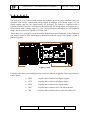
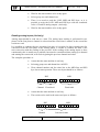
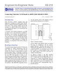
L a y o u t
The Ax4 (Ax2) Axis control board contains the hardware necessary to provide four (two) axis
channels with encoder counter and analog output. In addition 8 (0) analog inputs, 24 (16)
digital outputs and 48 (24) digital inputs are provided. The board is completed with a
keyboard and LCD interface and a battery backed RAM. All analog inputs and outputs are 12
bit resolution with a voltage range of +/-10V. All digital inputs and outputs are 24V industrial
range, and the outputs are capable of 350mA each.
Since there is no serigraphy on the board the identification and orientation of the connectors
and jumpers must be done matching this description with the layout of the board, visible in
following picture.
78L05
JP2
8
1
U41
U36
U35
UDN2981
JP3
0
R29
Q1
D3
U38
C82
HC597
DS7
8x4z7
8x.1u
470
8x10z
D52
D54
D56
D60
D58
D84
1K
U39
D62
D64
D66
D90
D70
D72
D74
DS5
D38
D78
D80
C52
.1u
U32
C53
.1u
D40
D42
D44
1K
DN10
U33
D4
D6
D8
D10
D12
D14
D16
8x4z7
8x.1u
D48
8x.1u
C11
D22
D24
D26
D28
D30
D32
DD4
DD3
IS6
.1u
IS7
10K
XC1736
C13
JP9
J1
JP7
75451D
IS4
C24
JP10
J2
C45
IS2
IS1
10
K1
%
IS8
C29
LM358
U1
XC3030
.1u
C23
.1u
.1u
DN
3
R1 R2 R6 R3
R4
C2
220.1u.1u2706K3K6K
K8 3 8
.1u
C3
U3
47u
C6
U22
R5
C12
.1u
26
LS
32
1K
.1u
75451D
JP6
22u
JP3
C30
U17
.1u
22u
+
C8
3K
+
3
R27R281%
244
75451D
.1u
U9
C7
U27
U21
JP26
J5
XC3030
.1u
78L05
470
820p
IS3
DN
6
U16
C1
XC3030
U46
DS9
47u
AD7890
470
.1u
XC1736
DN
2
U8
IS5
DD1
C42
+
DN5
.1u
U7
C27
DD2
.1u
.1u
XC1736
DN12
8x10z
D82
1K
470
LM311D
DS1
U2
.1u26
LS
32
+
C4
.1u
C9
U4
10K
U19
C54
.1u
D18
U34
D34
273
C15
U11
244
JP25
C20
U13
520
DN
1
C14
JP1JP1 JP1 JP1 JP1JP1 JP1 JP1
1 2 3 4 5 6 7 8
JP24
U10
244
C21
U14
520
C16
.1u
1K
U12
U15
DS1230
.1u
DN
4
470
DS2
245
JP1
JP1JP2 JP2 JP2 JP2
9 0 1 2 3
J4
8x10z
D21C64D23C65D25C66D27C67D29C68D31C69D33C70D35C71
8x4z7
DD5
8xHPCL600
D11
C59D13C60D15C61D17C62D19C63
D5 C56D7 C57D9 C58
D20
DD6
C43
2K2
.1u
U6
U20
JP5
D50
.1u
244
470
D46
DD7
8xBAV99
JP8
D98
HC597
DN
8
8x4z7
C28
C50
DS4
D37 C72D39C73D41C74D43C75D45C76D47C77D49C78D51C79
.1u
245
470
DN11
DD8
U45
R24R20 R26
C44
+
D96
.1u
.1u
U18
47u
8x10z
HC597
8x10z
D36
D76
8x.1u
470
8x4z7
1K
1
DS3
D94
U25
C35R15R16R11R18R13R14R12R17
C10
8x.1u
HC597
C25
K1K1
% % 1K
R25R19R23R21 R22 +
JP27
DS8
D92
U23
22u
C31
MAX532
C39 C41 C40
U26
1K
JP2
9
1K
1
C10
D69C93D71C94D73C95D75C96D77C97D79C98D81C99D830
D53C85D55C86D57C87D59C88D61C89D63C90D65C91D67C92
8x4z7
D88
+
K1K1K1K1
1K% %% %
.1u .1u .1u
LM324D
C38
.1u 1020 20 10 20 20
K1K1K11KK1K1K11K
%% % % % %
C32
+
47u
C10
C10
C10
C10
C10
C10
C10
C10
D851 D872 D893 D914 D935 D956 D977 D998
D68
DN
9
D86
C37
U24
P1
IS12
IS9
JP3 JP3
3 2
.1u
22u
C34
MAX532
C36
22K
C55R31 1K
1K
.1u
HC597
IS11
C10
9
HC04
.1u
22u
+
R7
C26
U28
8x10z
C81
2K2
.1u
820p
R30C80C51C46
.1u
5xHPCL600
C33
C84R32
4K
7
BYD17D
1
1K
DS6
IS13
1K
4K7
HC597
.1u U40
C83
.1u
IS10
DN
7
820
p
UDN2981
.1u.1u.1u
BC860B
JP3
1
2K2
U37
UDN2981
BYD17D
BYD17D
HC595 D1
HC595
HC595
D2 C47
C48
U42
U43
.1u
.1u U44
C49
.1u
75451D
U29
JP2
26 C5
LS
32 U5
.1u
.1u
C22
C19
+
JP4
C18
47u
8x.1u
C17
+
47u
LS
GN
LC
VC
CD
Figure 1: Ax4
Looking at the layout proceeding from top to bottom and left to right the following connectors
can be found:
•
JP28
34 poles male connector for digital outputs.
•
JP30
34 poles male connector for digital inputs.
•
JP29
34 poles male connector for digital inputs.
•
JP27
34 poles male connector for LCD and keyboard.
•
JP6
60 poles male connector for encoder and analog I/O.
Studio Ferraris
Ax4.doc
6/34
Studio Ferraris - Ax2000 System User Manual
Rev: 001 - Page: 7/34
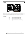
Figure 2: Ax2
The Ax2 board is a subset of the Ax4 board. In this manual, the description of all features will
follow the Ax4 layout and naming conventions. Where different for the Ax2 board the
different naming or features will be indicated in parenthesis.
Looking at the layout proceeding from top to bottom and left to right the following connectors
can be found:
•
JP29
34 poles male connector for digital outputs.
•
JP30
34 poles male connector for digital inputs.
•
JP26
34 poles male connector for LCD and keyboard.
•
JP24
60 poles male connector for encoder and analog I/O.
Studio Ferraris
Ax4.doc
7/34
Studio Ferraris - Ax2000 System User Manual
Rev: 001 - Page: 8/34
C o n n e c t o r s
The description of each connector here follows the orientation found in the picture and in the
real board.
JP28 (JP29) top-left
This is the digital output connector. In this connector there are pins for 24Volt supply and
ground. In addition each group of 8 outputs can be powered using a different power supply.
The connector is provided with key to minimize connection errors.
Pin 1, 2, 3, 4 are the 24V supply for output byte 0
Pin 5, 6, 7, 8 are the 24V supply for output byte 1
Pin 9 to 16 are the 8 outputs of byte 0
Pin 17 to 24 are the 8 outputs of byte 1
Pin 25 to 32 are the 8 outputs of byte 2 (N.C. on Ax2)
Pin 33, 34 are the supply ground
JP30 (not present) middle-left
This is the second digital input connector. In this connector there are pins for 24Volt supply
and ground. This connector is not present in the Ax2 board
The connector is provided with key to minimize connection errors.
Pin 1, 2, 3, 4 are the 24V supply for internal logic (must not be removed).
Pin 5, 6, 7, 8 are not connected
Pin 9 to 16 are the 8 inputs of byte 3
Pin 17 to 24 are the 8 inputs of byte 4
Pin 25 to 32 are the 8 inputs of byte 5
Pin 33, 34 are the supply ground
JP29 (JP30) bottom-left
This is the first digital input connector. In this connector there are pins for 24Volt supply and
ground.
The connector is provided with key to minimize connection errors.
Studio Ferraris
Ax4.doc
8/34
Studio Ferraris - Ax2000 System User Manual
Rev: 001 - Page: 9/34
Pin 1, 2, 3, 4 are the 24V supply for internal logic (must not be removed).
Pin 5, 6, 7, 8 are the 24V supply for output byte 3 (N.C. on Ax2)
Pin 9 to 16 are the 8 inputs of byte 0
Pin 17 to 24 are the 8 inputs of byte 1
Pin 25 to 32 are the 8 inputs of byte 2
Pin 33, 34 are the supply ground
JP27 (JP26) middle
This is the keyboard and display connector. On this connector there are the standard display
interface signals, as well as 8 buffered TTL outputs and 8 TTL inputs for a matrix keyboard.
The digital outputs can be also used to light LED, providing external current limiting resistor
for each. The digital inputs and outputs are totally uncommitted and under software control,
allowing for any mix of LED, direct keys and matrix keyboard. In the standard panel, as an
example, there are four direct LED, a keyboard matrix of four rows per eight columns (total
of 32 keys), and a text 4x20, or graphic 128x64 LCD display. Test software and samples are
given for this arrangement.
The connector is provided with key to minimize connection errors.
Pin 1, 2, are reserved (do not connect)
Pin 3 is the LCD contrast voltage adjustable from 0 to 5Volt with the on board trimmer.
Pin 4 is DS pin of the display interface
Pin 5 is RW pin of the display interface
Pin 6 is E pin of the display interface
Pin 7 to 14 are the DB pins of the display interface
Pin 15 is a ground connected to the board ground
Pin 16 is a 5Volt connected to the board power
Pin 17, 19, 21, 23, 25, 27, 29, 31 are the TTL outputs
Pin 18, 20, 22, 24, 26, 28, 30, 32 are the TTL inputs
Pin 34 is a 5Volt connected to the board power
Pin 33 is a ground connected to the board ground
Pin 34 is a 5Volt connected to the board power
Studio Ferraris
Ax4.doc
9/34
Studio Ferraris - Ax2000 System User Manual
Rev: 001 - Page: 10/34
JP6 (JP24) left
This is the axis and analog connector. On this connector there are the standard encoder inputs,
the analog inputs and outputs, as well as power and ground pins, and two signals for a touch
probe interface.
The connector is provided with key to minimize connection errors.
Pin 1, 2, are the analog ground
Pin 3 to 10 are the analog inputs pins.
Pin 11 is the +12V/+15V analog power supply
Pin 12 is the -12V/-15V analog power supply
Pin 13, 15, 17, 19 are the analog grounds
Pin 14, 16, 18, 20 are analog outputs
Pin 21 is a ground supply for external touch probe
Pin 22 is the touch probe output (LED)
Pin 23 is a 5V power supply for external touch probe
Pin 24 is the touch probe input
Pin 25 is a digital ground (shield 0)
Pin 26, 27, 28, 29, 30, 31, are the A+/A-, B+/B-, C+/C- signals of encoder 0
Pin 32 is a 5V power supply to the encoder 0
Pin 33 is a digital ground supply to the encoder 0
Pin 34 is a digital ground (shield 1)
Pin 35, 36, 37, 38, 39, 40, are the A+/A-, B+/B-, C+/C- signals of encoder 1
Pin 41 is a 5V power supply to the encoder 1
Pin 42 is a digital ground supply to the encoder 1
Pin 43 is a digital ground (shield 2)
Pin 44, 45, 46, 47, 48, 49 are the A+/A-, B+/B-, C+/C- signals of encoder 2
Pin 50 is a 5V power supply to the encoder 2
Pin 51 is a digital ground supply to the encoder 2
Pin 52 is a digital ground (shield 3)
Pin 53, 54, 55, 56, 57, 58 are the A+/A-, B+/B-, C+/C- signals of encoder 3
Pin 59 is a 5V power supply to the encoder 3
Pin 60 is a digital ground supply to the encoder 3
Studio Ferraris
Ax4.doc
10/34
Studio Ferraris - Ax2000 System User Manual
Rev: 001 - Page: 11/34
J u m p e r s
The description of jumper position here follows the orientation found in the picture and in the
real board.
On these boards there are a number of jumpers for special factory configuration. These
jumpers are implemented as a zero ohm resistor soldered on the board. Modification of these
settings is allowed only by permission, and for specific purposes.
Other user configurable jumpers can be modified to select the base address of the I/O and
memory spaces.
Memory address jumpers
The jumpers JP19 to JP23 (JP18..JP22 for Ax2) determine the base address of the battery
backed ram, present on the board.
There are five jumpers to select the highest addresses of the PC bus. JP23 (JP22), the
rightmost select A19 to JP19 (JP18) the leftmost that select A15. Inserting a jumper means
select the address to zero, removing a jumper selects one.
The default configuration maps the ram at D800:0..7FF and is:
A15
A16 A17 A18 A19
I/O address jumpers
The jumpers JP11 to JP18 (JP10..JP17 for Ax2) determine the base address of the I/O space.
There are eight jumpers to select the higher addresses of the PC bus. JP18 (JP17), the
rightmost select A9 to JP11 (JP10) the leftmost that select A2. Inserting a jumper means
select the address to zero, removing a jumper selects one.
The default configuration maps the I/O space at 280..283 and is:
A2
Studio Ferraris
A3
A4
A5
A6
Ax4.doc
A7
A8
A9
11/34
Studio Ferraris - Ax2000 System User Manual
Rev: 001 - Page: 12/34
P r o g r a m m i n g
The board span for four bytes of addressing in the I/O space, and 2K of memory space
The base address is defined by the jumper position. The memory is flat and can have any user
defined structure, while the I/O space is structured as follows:
BASE +
0
LOW
Low data byte. The meaning of this byte depend on
the function selected and should be combined with
MID and HIG.
BASE +
1
MID
Mid data byte. (see LOW).
BASE +
2
HIG
High data byte. (see LOW). Writing into this
register also starts the operation defined by the other
registers, so it should be written last.
BASE +
3
REG
Register for function selection and for status
checking.
The LOW, MID and HIG data byte are combined to form a 24 bit data. In some cases, where
less then 24 bits are required, only two data registers are combined.
Since writing in the HIG byte starts the defined operation, normally the sequence to give
commands should be the following:
1. Check if the state machine is available checking if bit 7 of REG is
zero (BUSY). Optionally wait. The maximum time to wait should be
less then 40 microseconds worst case.
2. Set up the REG for the required operation.
3. Prepare the data to be written and write it beginning from the LOW
byte and ending with the HIG.
4. Writing HIG starts the operation. If results are needed, then wait for
BUSY to return to zero.
5. (Optional) Read back the results.
Register
The REG byte is a dual function, read and write register. Few bits have meaning, unused bit
should be written as zero and read as don’t care. Used bits are:
BIT 0..1
Studio Ferraris
Channel select (Valid for counter and analog output and
some other peripheral)
Ax4.doc
12/34
Studio Ferraris - Ax2000 System User Manual
Rev: 001 - Page: 13/34
BIT 2..3
Group select. (Selects counters, latched counters, digital I/O,
or other type of peripherals).
BIT 4..5
Touch probe interface (bit 4 read probe status, bit 5 read latch
status, bit 4 write enable touch, bit 5 write enable touch probe
and reset flags latch)
BIT 6
Selects secondary inputs (Ax4 only)
BIT 7
Reset state machine if written one. Read as state machine
BUSY.
No operation should be performed on any Ax4 register if the state machine is busy. The only
allowed operation in this situation is reading the register to check the busy.
Reading encoder counters (Group 0)
To read the encoder counters it is necessary to follow a procedure to assure that the high byte
of a channel is corresponding to the low byte. Since the two bytes are read in different time,
the hardware have a latch that can be triggered upon software action, that freezes the counter
value during the reading. It is software responsibility to trigger the latch before reading and to
release it after. It is important to know that only the reading is frozen during this operation,
the counter itself is unaffected.
The counter is 16 bits wide and can be extended in software. Only the LOW and MID
addresses are used to read the counters. Selecting even channels, at the HIG byte it is possible
to read the flags status. Four bits gives information about the current and latched status of the
current and following channel. Reading the flags also triggers the latches to allow a consistent
reading of both channels. The software can read both flags (Ax2 only) before reading to have
consistent reading of all four counters.
The flags bytes is structured as follows:
BIT 0
Current status of C Channel of encoder 0 (2).
BIT 1
Latched status of C Channel of encoder 0 (2).
BIT 2
Current status of C Channel of encoder 1 (3).
BIT 3
Latched status of C Channel of encoder 1 (3).
BIT 4..7
Not used read as zero.
To read the counters the software must follow this sequence:
•
Assure that the state machine is not busy.
•
Select group zero and the required channel. The channels are paired
for what regards the flags, so channel 1 flags are in the same byte
(HIG) with the flags of channel 0 (selecting channel 0).
Studio Ferraris
Ax4.doc
13/34
Studio Ferraris - Ax2000 System User Manual
Rev: 001 - Page: 14/34
•
Read the flags (HIG byte). This operation latches both 0 (2) and 1 (3)
counters.
•
Read the LOW byte first and then the MID byte to complete the 16
bits of the counter. Reading the MID byte have also the effect of
releasing the latches. It is important to release both latches from the
current and the following channel. If the other channel reading is not
necessary, the software have still to make a dummy read in the MID
byte of that channel.
Reading encoder latches (Group 1)
An additional hardware latch can be triggered by the C channel of each encoder
independently, or together all four encoders upon an external trigger probe signal. The choice
is under software control through the ENAPALP bit (bit 5) of register. If this bit is HIG the C
channel is not used and the latches will be triggered by the touch probe input only. If this bit
is low the C channel of the encoders will trigger the latches, and the touch probe is not used,
although in this condition the status and reset bits related to the touch probe are still valid,
only the latches are not affected. This means that, during the home search the status of the
external touch probe can be still monitored, even if the signal cannot latch the counters. This
way the software can take any measure to prevent damage of the probe during the home
search.
Again, only the latches are frozen during this operation, the counter itself is unaffected.
To read the latches, whether they are triggered by the C channel or by the external touch
probe, the software must follow this sequence:
•
Assure that the state machine is not busy.
•
Select group one and the required channel.
•
Read the LOW byte and the MID byte to complete the 16 bits of the
counter.
•
If the reading is due to a C channel trigger, it is necessary to reset the
C channel flags latch, in order to be able to detect another pulse on
the same channel. This is done by toggling the Touch probe Enable
bit (ENAPALP) in the register. It is possible to set this bit and
immediately reset it, with to output instructions.
Using the touch probe
The touch probe is managed by two bits present in the register, bit 4 and bit 5. These two bits
have a different meaning on reading and writing, according to the following description:
BIT
read
4 Touch probe latch status. This latch is set by the first opening
on the touch probe and remains set even if the touch probe
Studio Ferraris
Ax4.doc
14/34
Studio Ferraris - Ax2000 System User Manual
Rev: 001 - Page: 15/34
closes again. This latch can be reset only under software
control.
BIT
read
5 Touch probe status. This bit gives the actual status of the
touch probe. The software can determine if the touch probe is
deflected or not.
BIT
write
4 Write one into this bit results in resetting the touch probe
latch. After this operation the latch is armed for the next
touch.
BIT
write
5 Write one into this bit to enable the touch latch signal to
actually trigger the counter latches. If this bit is zero the C
channel of each encoder will trigger the counter latches.
To use the hardware latches the software can follow this sequence:
•
Assure that the state machine is not busy.
•
Set the bit 5 and bit 4 of the register to enable and reset the touch
probe latch.
•
Wait until the bit 4 of the register reads back as one signaling that a
touch event has happened.
•
Go read the latches in the usual way.
•
Wait for the current probe status to be clear again indicating that the
touch is released (closed).
•
Reset the touch latch writing one into bit 4 (and also into bit 5 to
continue to enable the touch logic).
Reading Analog and digital I/O (Group 2)
All digital and analog I/O are grouped together under the group 2, the channel selects which
type of I/O.
Channel 0
Analog output X (low 12 bits) and Y (high 12 bits)
Channel 1
Analog output Z (low 12 bits) and W (high 12 bits) (Ax4
only)
Channel 2
Analog input (Ax4 only)
Channel 3
Digital I/O
The procedure how to format and read or write the analog I/O is described in the following
sections. This section will focus on reading the digital I/Os.
Studio Ferraris
Ax4.doc
15/34
Studio Ferraris - Ax2000 System User Manual
Rev: 001 - Page: 16/34
As described previously these accesses are done through the state machine, and it is very
important to wait for the busy flag before changing any bit in the register. Moreover, the
digital I/O are exchanged in a single operation, that is writing the digital outputs result in
reading the digital inputs.
On the Ax4 board there are two series of 24 inputs for one series of 24 output, so a bit in the
register is used to select which input series have to be exchanged with the output. If the
software needs to read both input series, it have to write the same output twice, selecting the
correct input series between the writes.
The complete procedure is as follows:
•
Assure that the state machine is not busy.
•
Select group two and channel three and first input series (bit 6 of
register low).
•
Write the LOW, MID and HIG byte with the required 24 output
values. It is important to write the HIG byte last, because this enables
the transfer to the real outputs.
•
Wait for the state machine to be ready again.
•
Read the LOW, MID and HIG byte of the first input series.
•
If Ax4 then select again group two and channel three and the second
input series (bit 6 of register high).
•
Write the LOW, MID and HIG byte with the same 24 output values.
It is important to write the HIG byte last, because this enables the
transfer to the real outputs.
•
Wait for the state machine to be ready again.
•
Read the LOW, MID and HIG byte of the second input series.
Writing analog outputs
Analog outputs are combined two channels at a time, the two 12 bit values results in a 24 bit
word to be written in the LOW, MID and HIG registers.
Analog outputs are write only, and always two at a time. A channel have to be selected in the
REG following the rule above.
The complete procedure is as follows:
•
Assure that the state machine is not busy.
•
Select group two and channel zero.
•
Write the LOW, MID and HIG byte with the combined value of X
and Y analog outputs. It is important to write the HIG byte last,
because this enables the transfer to the real outputs.
Studio Ferraris
Ax4.doc
16/34
Studio Ferraris - Ax2000 System User Manual
Rev: 001 - Page: 17/34
•
Wait for the state machine to be ready again.
•
Select group two and channel one.
•
There is no need to read the LOW, MID and HIG byte, so it is
possible to write the LOW, MID and HIG byte with the combined
value of Z and W analog outputs (Ax4 only).
•
Wait for the state machine to be ready again.
Reading analog inputs (Ax4 only)
Analog input should be read one at a time. The analog input reading is performed in two
phases. In the first phase a channel is selected and the conversion is started, in the second the
results are read.
It is possible to combine the two operation, but since it is required to leave enough time for
conversion from the start phase to the reading phase, it’s better to combine the start of the
next conversion with the reading of the previous. If the reading of the analog inputs is done
continuously this is usually not a problem, but must be remembered that setting up a channel
and starting the conversion, will result in getting the previous channel and value.
The complete procedure is:
•
Assure that the state machine is not busy.
•
Selecting group two and channel two in REG.
•
Write channel number and few other bits to the MID first and HIG
byte last to start operation. These two bytes should be as follows:
HIG
MID
Channel Fixed 0x10
Fixed 0x00
•
Assure that the state machine is not busy.
•
The results can be read in the same two bytes as follows:
HIG
Channel
Studio Ferraris
MID
Converted value
Ax4.doc
17/34
Studio Ferraris - Ax2000 System User Manual
Rev: 001 - Page: 18/34
It is important to note that the channel read back in this operation can be different than the
channel written before, because the written value will be used for the next conversion that
starts immediately, while the resulting channel is the channel for which the conversion has
been completed previously.
If all the channels are read in sequence the resulting channel should be the previous in the
sequence.
It is important to note that the writing (and reading) operation, starts also the conversion for
the selected channel, but the software must wait for the conversion to be complete (20uS
worst case) before sending a new request to the analog converter. The BUSY bit of the state
machine is of no help in this case, because the state machine has indeed finished its job
starting the conversion.
Reading Display and keyboard (Group 3)
Reading the display and the keyboard is direct and do not require the state machine, but since
the register must be set up for the group and channel, actually no other activity can take place
on the board, while reading these I/Os.
The group must be set to group 3 and the channel selects the operation, according to the
following table:
Channel 0
Write to display (LOW is command, MID is data)
Channel 1
Read from the display (LOW is status MID is data)
Channel 2
Keyboard (write sets the output, read gets the input values)
Channel 3
Not used
The actual command and data written to the display, or the value associated with each I/O for
the keyboard is under software control and depends on which LCD and which keyboard
layout are used. In the sample program there is a generic four row and eight columns
keyboard and four LED and two possibilities for the display: a standard 20x4 text LCD and a
standard graphic 128x64 LCD.
Program samples
#include
#include
#include
#include
#include
#include
#include
"stdio.h"
"stdarg.h"
"string.h"
"conio.h"
"dos.h"
"process.h"
"time.h"
Studio Ferraris
Ax4.doc
18/34
Studio Ferraris - Ax2000 System User Manual
Rev: 001 - Page: 19/34
///////////////////////////////////////////////////////////////////
// I/O Port adresses
#define BASE
0x280
#define LOW
BASE
#define MID
BASE + 1
#define HIG
BASE + 2
#define REGISTRO
BASE + 3
// Peripheral groups
#define COUNTGRP
#define LATCHGRP
#define IOGRP
#define LKFGRP
0x00
0x04
0x08
0x0C
// Channel definition for IOGRP
#define ANALOGXY
0x00
#define ANALOGZW
0x01
#define ANALOGIN
0x02
#define DIGITAL
0x03
// Channel definition for LKFGRP
#define LCDWRITE
0x00
#define LCDREAD
0x01
#define KEYBOARD
0x02
#define FLASH
0x03
// Bits
#define
#define
#define
#define
#define
#define
#define
#define
and masks for REGISTRO
CHANMSK
0x03
GRPMSK
0x0C
PALPLATCH
0x10
RESPALP
0x10
PALPIN
0x20
ENAPALP
0x20
IO1
0x40
BUSY
0x80
///////////////// Display defines
#define TEXTBASE
0
#define TEXTCOLS
22
#define TEXTROWS
8
#define TEXTSIZE
(TEXTCOLS*TEXTROWS)
#define TEXTPAGES
16
#define
#define
#define
#define
#define
GRAFBASE 0xB00
GRAFCOLS
22
GRAFROWS
8
GRAFSIZE
(GRAFCOLS*GRAFROWS*8)
GRAFPAGES
3
#define CGBASE
0x1800
///////////////////////////////////////////////////////////////////
int noprn = 0, ax2 = 0, newlcd = 0;
void usage(void)
{
printf("Studio Ing. Ferraris\nTest AX4/AX2 boards\n");
printf("usage: AX4TEST [?] [noprn] [ax2] [newlcd] ....\n\n");
printf("ESC to terminate\n\n");
}
Studio Ferraris
Ax4.doc
19/34
Studio Ferraris - Ax2000 System User Manual
Rev: 001 - Page: 20/34
void prnhelp(void)
{
printf("noprn: no error printout\n");
printf("ax2:
test for Ax2 (2 Assi, 24 in, 16 out)\n");
printf("newlcd: test grafic lcd (default text 20x4)\n");
printf("\n\n");
exit(0);
}
void kbflush(void)
{
while(kbhit())
if(getch() == 0x1B) exit(0);
}
// Escape exit
void beep(void)
{
sound(440);
delay(50);
nosound();
}
///////////////////////////////////////////////////////////////////
void testreg(void)
{
unsigned char o = 0;
unsigned char i;
clrscr();
cprintf("\rTest R/W Register\n\r");
while(!kbhit())
{
outp(REGISTRO, o);
i = inp(REGISTRO);
cprintf("out:%3X
in:%3X
xor:%3X
err:%3X\r",
o, i, o ^ i, (o ^ i) & 0x4F);
o++;
}
kbflush();
}
///////////////////////////////////////////////////////////////////
void testshift(void)
{
unsigned char o = 0;
unsigned char i, j;
clrscr();
cprintf("\rTest R/W Shift Register\n\r");
outp(REGISTRO, IOGRP + DIGITAL);
while(!kbhit())
{
outp(LOW, o);
outp(MID, ~o);
i = inp(LOW);
j = inp(MID);
if(i != o || j != ~o)
cprintf("out:%3X
inlow:%3X
xor:%3X
inmid:%3X
o, i, o ^ i, j, (~o ^ j) & 0xFF);
o++;
}
kbflush();
Studio Ferraris
Ax4.doc
xor:%3X\r",
20/34
Studio Ferraris - Ax2000 System User Manual
Rev: 001 - Page: 21/34
}
///////////////////////////////////////////////////////////////////
void readcnt(void)
{
unsigned int i, ax[4], flg[4];
unsigned char grp = COUNTGRP;
clrscr();
cprintf("\rTest Read Counters\n\r");
while(!kbhit())
{
for(i = 0; i < 4; i++)
{
outp(REGISTRO, grp | i);
if(!(i & 0x01))
// ogni gruppo di due contatori
flg[i] = inp(HIG);
// blocca i latch software
ax[i] = inp(LOW);
ax[i] |= inp(MID) << 8;
// sblocca i latch software
}
cprintf("X:%6d(%4X) Y:%6d(%4X) Z:%6d(%4X) W:%6d(%4X) Fx/y:%1X
Fz/w:%1X\r",
ax[0], ax[0], ax[1], ax[1], ax[2], ax[2],
ax[3], ax[3], flg[0], flg[2]);
if(flg[1] != flg[0] || flg[3] != flg[2])
{
unsigned int axl[4];
beep();
flg[1] = flg[0];
flg[3] = flg[2];
for(i = 0; i < 4; i++)
{
outp(REGISTRO, LATCHGRP | i);
axl[i] = inp(LOW);
axl[i] += inp(MID) * 256;
}
cprintf("\nX:%7d
Y:%7d
Z:%7d
W:%7d\r",
axl[0], axl[1], axl[2], axl[3]);
gotoxy(1, 2);
outp(REGISTRO, grp | ENAPALP);
// Reset home flags
}
}
}
kbflush();
///////////////////////////////////////////////////////////////////
void readprb(void)
{
unsigned int reg, i, ax[4], flg[4];
unsigned int axl[4];
unsigned char grp = COUNTGRP | ENAPALP;
unsigned char ltc = LATCHGRP | ENAPALP;
clrscr();
cprintf("\rTest Read Probe Latch\n\r");
while(!kbhit())
{
outp(REGISTRO, grp);
// Rises ENAPALP e reset RESPALP
reg = inp(REGISTRO);
cprintf("reg:%3X\n\r", reg);
for(i = 0; i < 4; i++)
Studio Ferraris
Ax4.doc
21/34
Studio Ferraris - Ax2000 System User Manual
Rev: 001 - Page: 22/34
{
outp(REGISTRO, grp | i);
if(!(i & 0x01))
flg[i] = inp(HIG);
ax[i] = inp(LOW);
ax[i] |= inp(MID) << 8;
// each two counters
// triggers the software latch
// releases the software latch
}
cprintf("X:%6d(%4X) Y:%6d(%4X) Z:%6d(%4X) W:%6d(%4X) Fx/y:%1X
Fz/w:%1X\r",
ax[0], ax[0], ax[1], ax[1], ax[2], ax[2],
ax[3], ax[3], flg[0], flg[2]);
for(i = 0; i < 4; i++)
{
outp(REGISTRO, ltc | i);
axl[i] = inp(LOW);
axl[i] += inp(MID) * 256;
}
cprintf("\nX:%7d
Y:%7d
Z:%7d
W:%7d\r",
axl[0], axl[1], axl[2], axl[3]);
if(reg & PALPLATCH)
{
beep();
// latch!
outp(REGISTRO, grp | RESPALP);
// Reset latch
}
gotoxy(1, 2);
}
kbflush();
}
///////////////////////////////////////////////////////////////////
void waitbusy(void)
{
unsigned int cnt;
for(cnt = 0; cnt < 10000; cnt++)
if((inp(REGISTRO) & BUSY) == 0) break;
if(cnt >= 100)
cprintf("loop:%7d\r", cnt);
}
///////////////////////////////////////////////////////////////////
void anlgout(int chan)
{
unsigned int x = 0, y = 2048;
unsigned char grp = IOGRP + chan;
clrscr();
if(chan == 0)
cprintf("\rTest Analog Out X, Y\n\r");
else
cprintf("\rTest Analog Out Z, W\n\r");
while(!kbhit())
{
waitbusy();
outp(REGISTRO, grp);
outp(LOW, (x & 0xFF));
outp(MID, (((x >> 8) & 0x0F) | ((y << 4) & 0xF0)));
outp(HIG, ((y >> 4) & 0xFF));
cprintf("%c:%6d %c:%6d\r", chan ? 'Z' : 'X', x, chan ? 'W' : 'Y', y);
x++;
y++;
if(x >= 4096) x = 0;
Studio Ferraris
Ax4.doc
22/34
Studio Ferraris - Ax2000 System User Manual
Rev: 001 - Page: 23/34
if(y >= 4096) y = 0;
}
kbflush();
}
///////////////////////////////////////////////////////////////////
void anlgin(void)
{
unsigned int val[8];
unsigned int cnt, i;
unsigned char grp = IOGRP + ANALOGIN;
clrscr();
cprintf("\rTest Analog In\n\r");
waitbusy();
while(!kbhit())
{
cprintf("\r");
for(i = 0; i < 8; i++)
{
outp(REGISTRO, grp);
outp(MID, 0);
outp(HIG, ((i << 5) | 0x10));
waitbusy();
cnt = inp(LOW) + (inp(MID) << 8);
cprintf("c%1X:%4d ", (cnt >> 12) & 0x7, cnt & 0xFFF);
}
}
}
kbflush();
///////////////////////////////////////////////////////////////////
unsigned char swapbit(unsigned char c)
{
return( ((c & 0x80) ? 0x01 : 0) |
((c & 0x40) ? 0x02 : 0) |
((c & 0x20) ? 0x04 : 0) |
((c & 0x10) ? 0x08 : 0) |
((c & 0x08) ? 0x10 : 0) |
((c & 0x04) ? 0x20 : 0) |
((c & 0x02) ? 0x40 : 0) |
((c & 0x01) ? 0x80 : 0) );
}
void digital(void)
{
unsigned char in[3], in1[3], out[3], xor[3], xor1[3];
int i;
unsigned char grp = IOGRP + DIGITAL;
unsigned char grp1 = IOGRP + DIGITAL + IO1;
clrscr();
cprintf("\rTest Digital I/O\n\r");
waitbusy();
for(i = 0; i < 3; i++)
in[i] = in1[i] = out[i] = 0;
for(i = 0; i < 50; i++)
{
waitbusy();
Studio Ferraris
// Spegne il reset
Ax4.doc
23/34
Studio Ferraris - Ax2000 System User Manual
Rev: 001 - Page: 24/34
outp(REGISTRO, grp);
outp(LOW, out[0]);
outp(MID, swapbit(out[1]));
outp(HIG, out[2]);
}
while(!kbhit())
{
waitbusy();
outp(REGISTRO, grp);
outp(LOW, out[0]);
outp(MID, swapbit(out[1]));
outp(HIG, out[2]);
waitbusy();
in[0] = inp(LOW);
in[1] = inp(MID);
in[2] = inp(HIG);
outp(REGISTRO, grp1);
outp(LOW, out[0]);
outp(MID, swapbit(out[1]));
outp(HIG, out[2]);
waitbusy();
in1[0] = inp(LOW);
in1[1] = inp(MID);
in1[2] = inp(HIG);
xor[0] = out[0] ^ in[0];
xor[1] = swapbit(out[1]) ^ in[1];
xor[2] = out[2] ^ in[2];
xor1[0] = out[0] ^ in1[0];
xor1[1] = swapbit(out[1]) ^ in1[1];
xor1[2] = out[2] ^ in1[2];
if(!noprn)
{
cprintf("o:%2X %2X %2X i:%2X %2X %2X x:%2X %2X %2X i1:%2X %2X %2X
x1:%2X %2X %2X\r",
out[0], swapbit(out[1]), out[2],
in[0], in[1], in[2],
xor[0], xor[1], xor[2],
in1[0], in1[1], in1[2],
xor1[0], xor1[1], xor1[2]);
if(xor[0] | xor[1] | xor[2] | xor1[0] | xor1[1] | xor1[2])
cprintf("\n");
}
if(--i < 0)
{
i = 5;
out[0]++;
out[1]++;
out[2]++;
waitbusy();
outp(REGISTRO, grp);
Studio Ferraris
Ax4.doc
24/34
Studio Ferraris - Ax2000 System User Manual
Rev: 001 - Page: 25/34
outp(LOW, out[0]);
outp(MID, swapbit(out[1]));
outp(HIG, out[2]);
delay(1);
}
delay(1);
}
kbflush();
}
void digital2(void)
{
unsigned char in[3], out[3], xor[3];
int i;
unsigned char grp = IOGRP + DIGITAL;
clrscr();
cprintf("\rTest Digital I/O\n\r");
waitbusy();
for(i = 0; i < 3; i++)
in[i] = out[i] = 0;
for(i = 0; i < 50; i++)
{
waitbusy();
// Charges the reset circuit
outp(REGISTRO, grp);
outp(LOW, out[0]);
outp(MID, swapbit(out[1]));
outp(HIG, out[2]);
}
while(!kbhit())
{
waitbusy();
outp(REGISTRO, grp);
outp(LOW, out[0]);
outp(MID, swapbit(out[1]));
outp(HIG, out[2]);
waitbusy();
in[0] = inp(LOW);
in[1] = inp(MID);
in[2] = inp(HIG);
xor[0] = out[0] ^ in[0];
xor[1] = swapbit(out[1]) ^ in[1];
xor[2] = out[2] ^ in[2];
if(!noprn)
{
cprintf("o:%2X %2X %2X i:%2X %2X %2X x:%2X %2X %2X\r",
out[0], swapbit(out[1]), out[2],
in[0], in[1], in[2],
xor[0], xor[1], xor[2]);
if(xor[0] | xor[1] | xor[2])
cprintf("\n");
}
if(--i < 0)
Studio Ferraris
Ax4.doc
25/34
Studio Ferraris - Ax2000 System User Manual
Rev: 001 - Page: 26/34
{
i = 5;
out[0]++;
out[1]++;
out[2]++;
waitbusy();
outp(REGISTRO, grp);
outp(LOW, out[0]);
outp(MID, swapbit(out[1]));
outp(HIG, out[2]);
delay(1);
}
delay(1);
}
kbflush();
}
///////////////////////////////////////////////////////////////////
void keyboard(void)
{
unsigned int cnt, i;
unsigned char grp = LKFGRP + KEYBOARD;
clrscr();
cprintf("\rTest Keyboard\n\r");
waitbusy();
cnt = 0;
while(!kbhit())
{
outp(REGISTRO, grp);
outp(LOW, ~(1 << cnt));
i = inp(LOW);
if(i != 0xFF)
cprintf("row: %2X val: %2X\r", cnt, ~i & 0xFF);
cnt++;
if(cnt >= 8) cnt = 0;
}
kbflush();
}
///////////////////////////////////////////////////////////////////
///////////////// Low level read/write data/command
void lcdgrfwrdata(unsigned char data)
{
const unsigned char write = LKFGRP + LCDWRITE;
outp(REGISTRO, write);
outp(LOW, data);
// Write LCD Data
}
void lcdgrfwrcmd(unsigned char cmd)
{
const unsigned char write = LKFGRP + LCDWRITE;
outp(REGISTRO, write);
outp(MID, cmd);
// Write LCD Command
}
unsigned char lcdgrfrddata(void)
{
const unsigned char read = LKFGRP + LCDREAD;
outp(REGISTRO, read);
Studio Ferraris
Ax4.doc
26/34
Studio Ferraris - Ax2000 System User Manual
return(inp(LOW));
Rev: 001 - Page: 27/34
// Read LCD Data
}
unsigned char lcdgrfrdstatus(void)
{
const unsigned char read = LKFGRP + LCDREAD;
outp(REGISTRO, read);
return(inp(MID));
// Read LCD Status
}
///////////////////////////////////////////////////////////////////
///////////////// Low level auto read/write data
void lcdgrfautowrite(unsigned char data)
{
while((lcdgrfrdstatus() & 0x08) != 0x08)
;
lcdgrfwrdata(data);
}
unsigned char lcdgrfautoread(void)
{
// TODO da implementare
return(0);
}
///////////////////////////////////////////////////////////////////
///////////////// Basic write data and command
void lcdgrfdt1(unsigned char d1)
{
while((lcdgrfrdstatus() & 0x03) != 0x03)
;
lcdgrfwrdata(d1);
}
void lcdgrfdt2(unsigned int d2)
{
while((lcdgrfrdstatus() & 0x03) != 0x03)
;
lcdgrfwrdata(d2 & 0xFF);
while((lcdgrfrdstatus() & 0x03) != 0x03)
;
lcdgrfwrdata(d2 >> 8);
}
void lcdgrfcmd(unsigned char cmd)
{
while((lcdgrfrdstatus() & 0x03) != 0x03)
;
lcdgrfwrcmd(cmd);
}
///////////////////////////////////////////////////////////////////
///////////////// High level commands
void lcdgrfCursor(unsigned char col, unsigned char row)
{
lcdgrfdt2((row << 8) | col);
lcdgrfcmd(0x21);
}
Studio Ferraris
Ax4.doc
27/34
Studio Ferraris - Ax2000 System User Manual
Rev: 001 - Page: 28/34
void lcdgrfOffset(unsigned int addr)
{
lcdgrfdt2(addr);
lcdgrfcmd(0x22);
}
void lcdgrfPointer(unsigned int addr)
{
lcdgrfdt2(addr);
lcdgrfcmd(0x24);
}
void lcdgrfTextHome(unsigned int addr)
{
lcdgrfdt2(addr);
lcdgrfcmd(0x40);
}
void lcdgrfTextArea(unsigned int cols)
{
lcdgrfdt2(cols);
lcdgrfcmd(0x41);
}
void lcdgrfGrafHome(unsigned int addr)
{
lcdgrfdt2(addr);
lcdgrfcmd(0x42);
}
void lcdgrfGrafArea(unsigned int cols)
{
lcdgrfdt2(cols);
lcdgrfcmd(0x43);
}
///////////////////////////////////////////////////////////////////
///////////////// Inizialization routine
void lcdgrfInit(void)
{
unsigned int i;
lcdgrfTextHome(TEXTBASE);
lcdgrfGrafHome(GRAFBASE);
lcdgrfTextArea(TEXTCOLS);
lcdgrfGrafArea(GRAFCOLS);
lcdgrfcmd(0x81);
lcdgrfOffset(CGBASE >> 11);
lcdgrfcmd(0x9E);
}
//Clear all RAM
lcdgrfPointer(0x0000);
lcdgrfcmd(0xB0);
for(i = 0; i < 8192U; i++)
lcdgrfautowrite(0x00);
lcdgrfcmd(0xB2);
//
//
//
//
//
//
//
//
//
// 8K
//
//
Text from 0 for 16 pages
Graficsfrom B00H for 3 pag
columns
columns
Mode set XOR, Internal CG
offs:00011 char 0x80 -> 0x1C00
Text on, Graph on, Curs on, Blink off
Begin of RAM
Auto write mode
blank code
Auto write mode off
///////////////////////////////////////////////////////////////////
///////////////// Base routines for AX4
Studio Ferraris
Ax4.doc
28/34
Studio Ferraris - Ax2000 System User Manual
Rev: 001 - Page: 29/34
// Write char and string on the display
void lcdgrfputc(int c)
{
lcdgrfdt1(c);
// Write char
lcdgrfcmd(0xC0);
// Increment pointer
}
// Move cursor (1,1)-(21,8)
void lcdgrfgotoxy(int col, int row)
{
lcdgrfCursor(col - 1, row - 1);
lcdgrfPointer((row - 1) * TEXTCOLS + col - 1);
}
typedef enum {
CUR_OFF,
CUR_ON,
CUR_BLINK,
} TCurType;
void lcdgrfcursor(TCurType t)
{
if(t == CUR_OFF)
lcdgrfcmd(0x9C);
//
else if(t == CUR_ON)
lcdgrfcmd(0x9E);
//
else if(t == CUR_BLINK)
lcdgrfcmd(0x9F);
//
lcdgrfcmd(0xA0);
//
}
// Move cursor
// Move pointer
// Cursor type definition
Text on, Graph on, Curs off, Blink off
Text on, Graph on, Curs on, Blink off
Text on, Graph on, Curs on, Blink on
1 line cursor
///////////////// Test LCD
void lcdgrf(void)
{
unsigned int i;
unsigned int j;
clrscr();
cprintf("\rTest LCD\n\r");
waitbusy();
lcdgrfInit();
lcdgrfPointer(TEXTBASE);
lcdgrfcmd(0xB0);
for(j = 0; j < TEXTPAGES; j++)
for(i = 0; i < TEXTSIZE; i++)
lcdgrfautowrite(j + 0x21);
lcdgrfcmd(0xB2);
// Fill each text page
// Auto write mode
// pages A,B,C,D,...
// Auto write mode off
lcdgrfPointer(GRAFBASE);
lcdgrfcmd(0xB0);
for(j = 0; j < GRAFPAGES; j++)
for(i = 0; i < GRAFSIZE; i++)
lcdgrfautowrite(j);
lcdgrfcmd(0xB2);
// Fills each grafic page
// Auto write mode
lcdgrfgotoxy(1, 1);
lcdgrfcursor(CUR_ON);
// set cursor
// pages 0,1,2
// Auto write mode off
lcdgrfPointer(CGBASE + 0x80 * 8);// Fills the C.G.
lcdgrfcmd(0xB0);
// Auto write mode
for(i = 0; i < 8; i++)
// 1 char
Studio Ferraris
Ax4.doc
29/34
Studio Ferraris - Ax2000 System User Manual
lcdgrfautowrite(0xFF >> i);
lcdgrfcmd(0xB2);
// triangle top/right
// Auto write mode off
lcdgrfgotoxy(1, 1);
lcdgrfcursor(CUR_ON);
// set cursor
Rev: 001 - Page: 30/34
for(j = 0; j < TEXTPAGES; j++)
{
lcdgrfgotoxy(j + 1, 1);
lcdgrfcursor((TCurType)(j & 0x3));
lcdgrfTextHome(j * TEXTSIZE);
getch();
}
lcdgrfcursor(CUR_OFF);
for(j = 0; j < GRAFPAGES; j++)
{
lcdgrfGrafHome(GRAFBASE + j * GRAFSIZE);
getch();
}
lcdgrfTextHome(TEXTBASE);
lcdgrfGrafHome(GRAFBASE);
lcdgrfPointer(TEXTBASE);
lcdgrfcmd(0xB0);
// Auto write mode
for(i = 0; i < 20; i++)
// 1 row
lcdgrfautowrite((i&0x01) ? 0x80: 0x5C);
lcdgrfcmd(0xB2);
// Auto write mode off
kbflush();
}
///////////////////////////////////////////////////////////////////
typedef enum {
LED_ERROR = 0x20,
LED_SHIFT = 0x40,
LED_READY = 0x80,
} LedMask;
unsigned char write = LKFGRP + LCDWRITE;
unsigned char read = LKFGRP + LCDREAD;
static int statoled = 0xE0; // Stato dei led
void waitlcdbusy(void)
{
waitbusy();
outp(REGISTRO, read);
while(inp(LOW) & BUSY)
;
}
void Lcdgotoxy(int col, int row)
{
static int trsl[4] = {0x00, 0x40, 0x14, 0x54};
waitlcdbusy();
outp(REGISTRO, write);
outp(LOW, (trsl[(row - 1)] + col - 1) | 0x80);
}
void Lcdprintf(char * fmt, ...)
{
static char buf[50];
int i = 0;
va_list ap;
Studio Ferraris
Ax4.doc
30/34
Studio Ferraris - Ax2000 System User Manual
Rev: 001 - Page: 31/34
va_start(ap, fmt);
vsprintf(buf, fmt, ap);
while(buf[i])
{
waitlcdbusy();
outp(REGISTRO, write);
outp(MID, (char)buf[i++]);
}
va_end(ap);
}
void LedOn(int msk)
{
statoled &= ~msk;
waitbusy();
outp(REGISTRO, LKFGRP + KEYBOARD);
outp(LOW, statoled);
}
void LedOff(int msk)
{
statoled |= msk;
waitbusy();
outp(REGISTRO, LKFGRP + KEYBOARD);
outp(LOW, statoled);
}
static int InitLcdChar(unsigned char c)
{
time_t ini, fin;
outp(REGISTRO, read);
time(&ini);
while(inp(LOW) & BUSY)
{
time(&fin);
if(difftime(fin, ini) > 2.)
break;
}
if((inp(LOW) & BUSY) == 0)
{
outp(REGISTRO, write);
outp(LOW, c);
return(1);
}
else
{
LedOn(LED_ERROR);
return(0);
}
}
// LCD Inizialization
void InitLcd(void)
{
delay(100);
outp(REGISTRO, write);
outp(LOW, 0x30);
delay(100);
outp(REGISTRO, write);
Studio Ferraris
// Set 8 bit interface ...
// Set 8 bit interface again ...
Ax4.doc
31/34
Studio Ferraris - Ax2000 System User Manual
outp(LOW, 0x30);
delay(100);
outp(REGISTRO, write);
outp(LOW, 0x30);
Rev: 001 - Page: 32/34
// Set 8 bit interface and again
// Now use display busy flag
if(!InitLcdChar(0x38)) return;
if(!InitLcdChar(0x08)) return;
if(!InitLcdChar(0x01)) return;
if(!InitLcdChar(0x06)) return;
if(!InitLcdChar(0x0E)) return;
//
//
//
//
//
Set 8 bit, 2 line, 5x7
Display Off
Clear LCD and Home
Mode increment
Display and cursor on
}
void lcd(void)
{
static o = 0;
InitLcd();
clrscr();
cprintf("\rTest Text LCD\n\r");
while(!kbhit())
{
waitbusy();
Lcdgotoxy(1, 1);
Lcdprintf("------TEST LCD------");
Lcdgotoxy(1, 2);
Lcdprintf("abcdefghijklmnopqrst");
Lcdgotoxy(1, 3);
Lcdprintf("ABCDEFGHIJKLMNOPQRST");
Lcdgotoxy(1, 4);
Lcdprintf("0123456789[]<>()%&!#");
switch(o++ % 6)
{
case 0:
LedOn(LED_ERROR);
break;
case 1:
LedOn(LED_SHIFT);
break;
case 2:
LedOn(LED_READY);
break;
case 3:
LedOff(LED_ERROR);
break;
case 4:
LedOff(LED_SHIFT);
break;
case 5:
LedOff(LED_READY);
break;
}
delay(200);
}
kbflush();
}
#define hash(i, j) ((i * j * 1133) & 0xFF)
void mem(void)
{
unsigned char far * pmem;
Studio Ferraris
Ax4.doc
32/34
Studio Ferraris - Ax2000 System User Manual
Rev: 001 - Page: 33/34
int i;
static int j = 0;
pmem = (unsigned char far *)MK_FP(0xD800, 0);
clrscr();
cprintf("\rTest Mem\n\r");
while(!kbhit())
{
for(i = 0; i < 2048; i++)
{
pmem[i] = hash(i, j);
/* write memory */
if(pmem[i] != hash(i, j) && !noprn)
/* read memory */
printf("Error mem: %3X - read: %3X - written: %3X - xor %3x\n",
i, pmem[i], hash(i, j), (pmem[i] ^ hash(i, j)));
}
for(i = 0; i < 2048; i++)
{
if(pmem[i] != hash(i, j) && !noprn)
/* read again */
printf("Error mem: %3X - read: %3X - written: %3X - xor %3x\n",
i, pmem[i], hash(i, j), (pmem[i] ^ hash(i, j)));
}
j++;
}
kbflush();
}
///////////////////////////////////////////////////////////////////
void main(int argc, char *argv[])
{
usage();
while(--argc)
{
if(!stricmp(argv[argc], "noprn")) noprn = 1;
if(!stricmp(argv[argc], "ax2")) ax2 = 1;
if(!stricmp(argv[argc], "newlcd")) newlcd = 1;
if(!stricmp(argv[argc], "?")) help = 1;
}
if(help)
{
prnhelp();
exit(0);
}
sleep(1);
// Wait logo
clrscr();
testreg();
testshift();
readcnt();
readprb();
anlgout(ANALOGXY);
if(!ax2)
{
anlgout(ANALOGZW);
anlgin();
digital();
}
else
digital2();
keyboard();
if(newlcd)
lcdgrf();
Studio Ferraris
Ax4.doc
33/34
Studio Ferraris - Ax2000 System User Manual
Rev: 001 - Page: 34/34
else
lcd();
mem();
}
Studio Ferraris
Ax4.doc
34/34