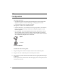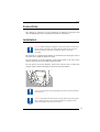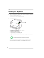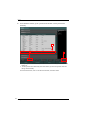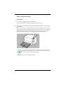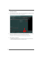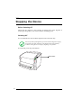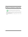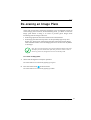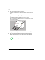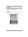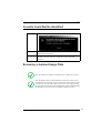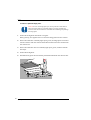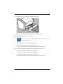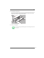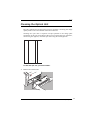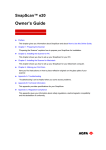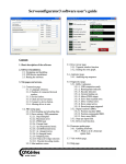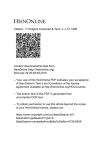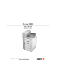
1
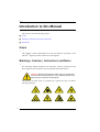
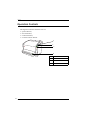
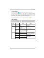
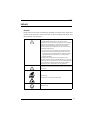
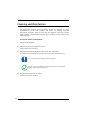
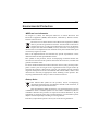
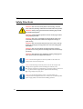
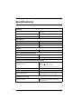
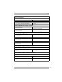
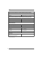
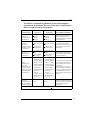
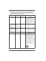
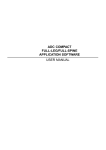
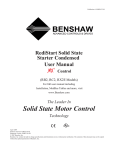
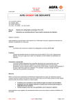
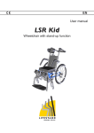
CR 10-X
(type 5151/100)
CR10-X
User Manual
2491A EN 2012-04-06
CR 10-X
0413
Manufacturer: Agfa HealthCare NV, Septestraat 27, B-2640 Mortsel - Belgium
For more information on Agfa products and Agfa HealthCare products, please visit www.agfa.com.
Agfa and the Agfa rhombus are trademarks of Agfa-Gevaert N.V., Belgium or its affiliates. CR 10-X, NX, ADC
QS and ADC VIPS are trademarks of Agfa HealthCare N.V., Belgium or one of its affiliates. All other trademarks
are held by their respective owners and are used in an editorial fashion with no intention of infringement.
Agfa HealthCare N.V. makes no warranties or representation, expressed or implied, with respect to the accuracy, completeness or usefulness of the information contained in this document and specifically disclaims warranties of suitability for any particular purpose. Products and services may not be available for your local area.
Please contact your local sales representative for availability information. Agfa HealthCare N.V. diligently
strives to provide as accurate information as possible, but shall not be responsible for any typographical error.
Agfa HealthCare N.V. shall under no circumstances be liable for any damage arising from the use or inability to
use any information, apparatus, method or process disclosed in this document. Agfa HealthCare N.V. reserves
the right to make changes to this document without prior notice.
Copyright 2012 Agfa HealthCare N.V.
All rights reserved.
Published by Agfa HealthCare N.V.
B-2640 Mortsel - Belgium.
No part of this document may be reproduced, copied, adapted or transmitted in any form or by any means
without the written permission of Agfa HealthCare N.V.
Date of the latest revision of the user manual: 2012-04-06
2
2491A EN 2012-04-06
CR 10-X
Table of Contents
Chapter 1: Introduction.................................................................. 5
Introduction to this Manual ......................................................................... 6
Scope .............................................................................................................. 6
Warnings, Cautions, Instructions and Notes..................................................... 6
Disclaimer ....................................................................................................... 7
Introduction to CR 10-X ............................................................................... 8
Intended Use ................................................................................................... 9
Intended User.................................................................................................. 9
Configuration................................................................................................ 10
Operation Controls ........................................................................................ 12
System Documentation ................................................................................. 14
Training ........................................................................................................ 15
Product Complaints ....................................................................................... 15
Compatibility ................................................................................................ 16
Compliance ................................................................................................... 17
Connectivity .................................................................................................. 19
Installation .................................................................................................... 19
Labels............................................................................................................ 21
Cleaning and Disinfection.............................................................................. 24
Patient data security ...................................................................................... 25
Maintenance ................................................................................................. 26
Environmental Protection.............................................................................. 27
Safety Directions ........................................................................................... 28
Quality Control.............................................................................................. 30
Chapter 2: Getting Started with the CR 10-X................................. 31
Starting the Digitizer ................................................................................. 32
Basic Workflow .......................................................................................... 33
Stopping the Device ................................................................................... 38
Chapter 3: Operating CR 10-X ...................................................... 39
Reading an Emergency Image Plate ........................................................... 40
Re-erasing an Image Plate.......................................................................... 41
Reading the Initialization Data of an Image Plate ...................................... 43
Expiry of Image Plates................................................................................ 45
Upcoming Expiry of the Image Plate .............................................................. 45
Expired Image Plate....................................................................................... 45
2491A EN 2012-04-06
3
CR 10-X
Troubleshooting ........................................................................................ 46
Error Viewer .................................................................................................. 47
Connection Problems.....................................................................................48
Cassette Could Not Be Identified....................................................................49
Removing a Jammed Image Plate...................................................................49
Behavior in Case of Power Failure ..................................................................54
Cleaning the Optical Unit...............................................................................55
Appendix A: Equipment Information Sheet ................................... 57
Specifications ............................................................................................ 58
Appendix B: Remarks for HF-emission and immunity ................... 61
Remarks for HF-emission and immunity ................................................... 62
4
2491A EN 2012-04-06
Chapter
Introduction
This chapter covers the following topics:
T
Introduction to this Manual
T
Introduction to CR 10-X
1
CR 10-X
Introduction to this Manual
This section covers the following topics:
Q Scope
Q Warnings, Cautions, Instructions and Notes
Q Disclaimer
Scope
This manual contains information for safe and effective operation of the
CR 10-XTM digitizer, further referred to as the digitizer.
Warnings, Cautions, Instructions and Notes
The following samples illustrate how warnings, cautions, instructions and
notes appear in this document. The text explains their intended use.
WARNING: Warnings are directions which, if they are not followed,
can cause fatal or serious injuries to a user, engineer, patient or any
other person or can lead to a mistreatment.
The purpose of safety icons is to indicate at a glance the type of caution,
warning or danger.
6
Introduction
2491A EN 2012-04-06
CR 10-X
Caution: Cautions are directions which, if they are not followed, can
cause damage to the equipment described in this manual or any other
equipment or goods and can cause environmental pollution.
Instruction: This sign is used typically in combination with the warning sign
when providing a specific instruction, which if followed exactly, should avoid
the subject of the warning.
Note: Notes provide advice and highlight unusual points. A note is not
intended as an instruction.
Disclaimer
Agfa assumes no liability for use of this document if any unauthorized
changes have been made to the content or format.
Every care has been taken to ensure the accuracy of the information in this
document. However, Agfa assumes no responsibility or liability for errors,
inaccuracies or omissions that may appear in this document. To improve
reliability, function or design Agfa reserves the right to change the product
without further notice. This manual is provided without warranty of any kind,
implied or expressed, including, but not limited to, the implied warranties of
merchantability and fitness for a particular purpose.
Note: In the United States, Federal Law stipulates that medical devices
should only be sold to, distributed and used by or by order of a licensed
physician.
2491A EN 2012-04-06
Introduction
7
CR 10-X
Introduction to CR 10-X
This section covers the following topics:
Q Intended Use
Q Intended User
Q Configuration
Q Operation Controls
Q System Documentation
Q Training
Q Product Complaints
Q Compatibility
Q Compliance
Q Connectivity
Q Installation
Q Labels
Q Cleaning and Disinfection
Q Patient data security
Q Maintenance
Q Environmental Protection
Q Safety Directions
Q Quality Control
8
Introduction
2491A EN 2012-04-06
CR 10-X
Intended Use
The digitizer is part of a CR system, further containing a cassette, image plate
and modality workstation. The CR system is used in a radiological
environment by qualified staff to read-out, process and route static X-ray
radiographic images.
The cassette is used to protect the image plate from light and damages during
X-ray exposure, transport and handling.
The image plate is used to capture the static X-ray radiographic images; the
image plate is scanned by the digitizer.
The digitizer is used to scan an X-ray exposed image plate; it results into a
digital image which is sent to the dedicated workstation.
The modality workstation is used to process and route the digital images from
the digitizer.
Intended User
This manual has been written for trained users of Agfa products and trained
diagnostic X–ray clinical personnel who have received proper training.
Users are those persons who actually handle the equipment and those who
have authority over the equipment.
Before attempting to work with this equipment, the user must read,
understand, note and strictly observe all warnings, cautions and safety
markings on the equipment.
2491A EN 2012-04-06
Introduction
9
CR 10-X
Configuration
The system consists of:
• the CR 10-X digitizer for image plates retaining latent X-ray images. The
digitizer accepts one cassette containing one image plate at a time.
• cassette and plate system: CR MD1.0 General.
The digitizer can be used in combination with:
• the NX workstation, a CR workstation for image acquisition, identification,
image processing and image transmission of digitized images received
from the digitizer.
• UPS (optional): the uninterruptible power system (UPS) protects the PC
when the main power supply has crashed, and avoids the loss of images.
UPS configuration requires special software. This software will be installed
and configured by an Agfa service technician.
CR10-X
digitizer
Control PC
Dedicated configuration
To install the UPS into the system:
1
Plug the UPS power cord into the input connector at the UPS rear panel.
2
Plug the other side of the UPS power cord into a power outlet.
3
Plug the digitizer, NX workstation and monitor into the appropriate UPS output
receptacles.
In case of power failure, the batteries of the UPS supply power to the digitizer, the NX
workstation and monitor.
10
Introduction
2491A EN 2012-04-06
CR 10-X
Full Leg Full Spine Application Components
• CR Full Body Cassette Holder
• Anti-scatter grid (optional)
• CR EasyLiftTM (optional)
For more information and instructions on the FLFS application, refer to the
document 4408, “CR Full Leg Full Spine User Manual”.
2491A EN 2012-04-06
Introduction
11
CR 10-X
Operation Controls
The digitizer interfaces with the user via:
•
•
•
•
a power button,
an erase button,
a status indicator,
a cassette release button.
1
2
CR10-X
3
4
12
Introduction
1
Power button
2
Erase button
3
Status indicator
4
Cassette release button
2491A EN 2012-04-06
CR 10-X
The Erase Button
Press the erase button
to start the erasing cycle of an image plate.
After pressing the erase button, the status indicator is continuously lighting
up in blue and the digitizer starts erasing the image plate of the cassette
inserted next. If no cassette with image plate has been inserted after 60
seconds, the system automatically returns to standby mode.
For more information, refer to ‘Re-erasing an Image Plate’ on page 41.
Status Indicator
The indicator informs the user by light signals about the status of the digitizer.
It is positioned at the front of the digitizer, so that it is visible from a distance.
Color
Blue
Constant/
Blinking
Constant
Constant
Green
Action
Activating the erasing
cycle
Insert cassette to erase the
image plate.
• Standby mode
(Ready)
• Proceed.
• Cassette is ready for
removal
• Remove cassette.
Blinking
Busy with scanning,
erasing and return of the
IP into cassette
Constant
Error
Blinking
slowly
Digitizer not ready
Blinking fast
Digitizer not connected
to Error Viewer UI
Blinking - 3
pulses
Digitizer not connected
to control PC
Red
2491A EN 2012-04-06
Status
Wait.
Consult the Error Viewer UI
(User Interface) messages on
the control PC. Refer to section
‘Troubleshooting’.
Refer to section
‘Troubleshooting’.
Introduction
13
CR 10-X
System Documentation
The documentation shall be kept with the system for easy reference. Technical
documentation is available in the product service documentation which is
available from your local support organization.
The user documentation consists of:
Q CR 10-X User Documentation CD (digital media).
Q NX User Documentation CD (digital media).
Q Getting Started material.
The CR 10-X User Documentation contains:
Q CR 10-X User Manual (this document), document 2491.
Q AGFA CR Plates and Cassettes (CR MD1.0 General) User Manual, document
2492.
Q CR Full Leg Full Spine User Manual, document 4408 (available on NX User Documentation CD).
The Getting Started material contains:
Q Getting Started with NX, document 4417.
Q Getting started with CR 10-X, document 2493.
14
Introduction
2491A EN 2012-04-06
CR 10-X
Training
The user must have received adequate Agfa training on the safe and effective
use of the product before attempting to work with it. Training requirements
may vary from country to country. The user should ensure that training is
received in accordance with local laws or regulations that have the force of
law. Your local Agfa representative can provide further information on
training.
The user must note the following information in the preliminary section of
this manual:
Q Intended Use
Q Intended User
Q Safety Directions
Product Complaints
Any health care professional (for example a customer or a user) who has any
complaints or has experienced any dissatisfaction in the quality, durability,
reliability, safety, effectiveness or performance of this product must notify
Agfa.
If the device malfunctions and may have caused or contributed to a serious
injury of a patient, Agfa must be notified immediately by telephone, fax or
written correspondence to the following address:
Agfa Service Support - local support addresses and phone numbers listed on
www.agfa.com
Agfa HealthCare N.V. - Septestraat 27 - 2640 Mortsel, Belgium.
Agfa HealthCare N.V. - Fax +32 3 444 7094.
2491A EN 2012-04-06
Introduction
15
CR 10-X
Compatibility
The digitizer must only be used in combination with other equipment or
components if these are expressly recognized by Agfa as compatible. A list of
such equipment and components is available from Agfa service on request.
Changes or additions to the equipment must only be carried out by persons
authorized to do so by Agfa. Such changes must comply with best engineering
practices and all applicable laws and regulations that have the force of law
within the jurisdiction of the hospital.
Accessory equipment connected to any interfaces must be certified according
to the respective IEC standards (e.g. IEC 950 for data processing equipment
and IEC 60601-1 for medical equipment). Furthermore all configurations
shall comply with the valid version of the system standard IEC 60601-1-1.
Everybody who connects additional equipment to the signal input part or
signal output part configures a medical system, and is therefore responsible
that the system complies with the requirements of the valid version of the
system standard IEC 60601-1-1. If in doubt, consult your local service
organization.
16
Introduction
2491A EN 2012-04-06
CR 10-X
Compliance
The digitizer has been designed in accordance with the MEDDEV Guidelines
relating to the application of Medical Devices and have been tested as part of
the conformity assessment procedures required by 93/42/EEC MDD
(European Council Directive 93/42/EEC on Medical Devices).
The digitizer has been designed in accordance with the IEC 60601-1: Medical
electrical equipment - Part 1: General requirements for basic safety.
The digitizer complies with the safety regulations for:
Quality Management
• ISO 13485:2003 + Cor. 1: 2009 Medical devices - Quality management
systems - requirements for regulatory purposes
• IEC 62366 Medical devices - application of usability engineering to medical
devices, first edition, October 2007
• IEC 62304 Medical Software Life Cycle Processes
Medical Electrical Equipment
• IEC 60601-1: second edition 1988-12 Medical electrical equipment,
•
•
•
•
•
General requirements for safety, incl. amendment 1 1991-11 and
amendment 2,1995-03
IEC 601-1-1:1992/A1:1995 / EN 60601-1-1:1993/A1:1996 Medical
electrical equipment - Part 1: General requirements for safety -1. Collateral
standard: Safety requirements for medical electrical systems
IEC/EN 60601-1-4:1996 Medical electrical equipment - Part 1-4: General
requirements for safety - Collateral standard: Programmable electrical
medical systems, inclusive amendment 1:1999
IEC 60601-1: third edition 2005-12 Medical electrical equipment, General
requirements for safety
UL60601-1:2005 Medical electrical equipment, General requirements for
safety (Adopted IEC 60601-1:2005, third edition, 2005-12), Includes
Corrigendum 1:2011
CAN/CSA-C22.2 NO. 60601-1-08 - Medical Electrical Equipment - Part 1:
General Requirements for Basic Safety and Essential Performance
(Adopted IEC 60601-1:2005, third edition 2005-12)
2491A EN 2012-04-06
Introduction
17
CR 10-X
Laser Products
• IEC 60825-1: 1993 Safety of laser products Part 1: Equipment
classification, requirements and user's guide + corr. February 1995 +
amendment A1: 1997 + amendment A2. 2001
Electromagnetic Compatibility
• IEC 60601-1-2:2007 Medical electrical equipment -part1.2: General
requirements for safety - collateral standard: electromagnetic compatibility
- requirements and tests
• FCC part 15 (USA)
• CSA 22.2 No. 601.1.2 (Canada)
Waste
• WEEE 2002/96/EC, amended by Directive 2003/108/EC
• RoHS Directive 2002/95/EC
Labeling
• EN 980:2008 Symbols for use in the labeling of medical devices
• EN 1041:1998, Information supplied by the manufacturer with medical
devices
Note: The CR 10-X is in compliance with the EG regulation 93/42/EEC
Directive (Medical Device).
Radio Interference Suppression
It is hereby certified that the digitizer has interference suppression according
to the EN 55011 Class A as well as the FCC Rules CR47 Part 15 Class A.
WARNING: This equipment has been tested and found to comply
with the limits for a Class A digital device, pursuant to part 15 of the
FCC Rules. These limits are designed to provide reasonable
protection against harmful interference when the equipment is
operated in a commercial environment. This equipment generates,
uses and can radiate radio frequency energy and, if not installed and
used in accordance with the instruction manual, may cause harmful
interference to radio communications. Operation of this equipment
in a residential area is likely to cause harmful interference in which
case the user will be required to correct the interference at his own
expense.
18
Introduction
2491A EN 2012-04-06
CR 10-X
Connectivity
The digitizer is connected to the workstation via Ethernet connection and
uses the DICOM protocol to communicate with the workstation.
Installation
Caution: When installing the digitizer, care must be taken to ensure that
there is either a mains plug or an all-cable disconnecting device in the
internal installation fitted near the digitizer and that it is easily
accessible.
The digitizer is equipped with handles at the bottom left and right sides to
move the device easily to another location.
For two persons to lift the digitizer, each should stand at the side of the
digitizer and hold it by the handle with both hands.
CR10-X
For one person to lift the digitizer, remove the cassette unit to reduce the
weight, stand in front of the digitizer and hold it by the handles.
Caution: Do not lift the device by holding the cassette unit or by holding
the back cover.
Caution: The digitizer and the cassette storage shall be protected against
direct radiation in such a way, that the annual dose equivalent at the
place of installation will not exceed 1 mSv/a.
2491A EN 2012-04-06
Introduction
19
CR 10-X
Caution: If the digitizer is installed inside an X-ray room it must be
protected from stray radiation by proper shielding.
WARNING: The device is a table-top digitizer. The structure and
stability of the table used need to be suitable in relation with the size
and weight of the system. Do not use excessive force when inserting
cassettes in the digitizer as the device may slip or drop off the table.
Use a non-slip-mat below the digitizer or other anti-skid measures.
The table should not be subject to excessive shock and vibrations
from other sources, as this may disturb the operation of the digitizer.
The digitizer complies with the EN 60601-1 and UL 60601-1 standards for
Medical Electrical Equipment. This means that, although it is absolutely safe,
patients may not come in direct contact with the equipment. Therefore the
operator console must be placed outside a radius of 1.5 m (EN) or 1.83 m (UL)
around the patient (according to the local valid regulation).
R = 1.5 m (1.83 m)
Patient environment
h= 2.5 m
(2.29 m)
Patient environment
20
Introduction
2491A EN 2012-04-06
CR 10-X
Labels
General
Always take into account the markings and labels provided on the inside and
outside of the machine. A brief overview of these markings and labels and
their meaning is given below.
Safety warning, indicating that the manuals should be
consulted before making any connections to other
equipment. The use of accessory equipment not complying
with the equivalent safety requirements of this digitizer
may lead to a reduced level of safety of the resulting
system. Consideration relating to the choice of accessory
equipment shall include:
• Use of the accessory equipment in the patient vicinity,
• Evidence that the safety certification of the accessory
equipment has been performed in accordance with the
appropriate IEC 601-1 and IEC 601-1-1 harmonized
national standard.
In addition all configurations must comply with the
medical electrical systems standard IEC 601-1-1. The party
that makes the connections acts as system configurator and
is responsible for complying with the systems standard.
If required contact your local service organization.
In order to reduce the risk of electric shock, do not remove
any covers.
Caution hot:
Keep hands clear from the erasure unit.
Power button
2491A EN 2012-04-06
Introduction
21
CR 10-X
Type label
Date of manufacture
Manufacturer
22
Introduction
2491A EN 2012-04-06
CR 10-X
Safety Instructions for Laser Products
CAUTION!
CUIDADO!
CLASS 3B LASER RADIATION:
WHEN OPEN AVOID DIRECT
EXPOSURE TO THE BEAM!
RAYO LASER CLASE 3B:
EVITAR LA EXPOSICIÓN AL HAZ
CUANDO LA TAPA ESTÁ ABIERTA.
VORSICHT !
ATTENTION!
LASERSTRAHLUNG KLASSE 3B:
WENN ABDECKUNG GEÖFFNET
NICHT DEM STRAHL AUSSETZEN!
FAISCEAU LASER CLASSE 3B:
QUAND CAPOT OUVERT ÉVITER
DE S´EXPOSER AU RAYÓN!
CLASS 1 LASER PRODUCT
APPAREIL A LASER DE CLASSE 1
LASERKLASSE 1
The digitizer is a Class 1 Laser Product. It uses one laser diode of a 80 mW
type, classification class IIIb, wavelength 640-670 nm. The laser beam
divergence is 120 - 350 mrad. The laser beam’s deflection frequency is 70 1/s
up to 90 1/s.
Under normal operating conditions - device with all covers - there can be no
laser radiation outside the digitizer.
The technical concept does not allow the user to remove the top cover.
The cassette unit and the back cover can be removed e.g. to solve cassette or
image plate jams. The digitizer must be switched off before removing the
cassette unit or opening the back of the device.
WARNING: User interventions other than those described in this
manual can be hazardous with regard to laser radiation.
2491A EN 2012-04-06
Introduction
23
CR 10-X
Cleaning and Disinfection
All appropriate policies and procedures should be followed to avoid
contamination of the staff, patients and device. All existing universal
precautions should be taken to avoid that the digitizer comes into contact
with potential contaminations. Details about cleaning can be found in the
following pages.
To clean the exterior of the digitizer:
1
Switch off the digitizer.
2
Remove the power plug from the socket.
Switch off the UPS, if installed.
3
Wipe the exterior of the digitizer with a clean, soft, damp cloth.
Use a mild soap or detergent if required but never use ammonia-based cleaner.
Caution: Make sure no liquid gets in the digitizer.
Note: Do not open the digitizer for cleaning. No components inside the
digitizer require cleaning by the user.
4
Plug the power plug into the socket.
Switch on the UPS, if installed.
24
Introduction
2491A EN 2012-04-06
CR 10-X
Patient data security
It is the responsibility of the hospital to ensure how the patients’ legal
requirements are to be met, how the security of the patient records are:
•
•
•
•
maintained and tested,
audited,
administered locally to cover risks from third party access,
how the availability of the services is to be maintained in the event of
disaster.
It is the responsibility of the hospital to ensure how types of access are
identified, classified and reasons for access are justified.
2491A EN 2012-04-06
Introduction
25
CR 10-X
Maintenance
Preventive Maintenance
No regular preventive maintenance is required other than described further in
this chapter.
Cleaning and Disinfection
Refer to section ‘Cleaning and Disinfection’ on page 24.
26
Introduction
2491A EN 2012-04-06
CR 10-X
Environmental Protection
WEEE end user information
On August 13, 2005, the European Directive on Waste Electrical and
Electronic Equipment (WEEE) 2002/96/EC, amended by Directive 2003/
108/EC came into force.
The directive on Waste Electrical and Electronic Equipment (WEEE)
aims to prevent the generation of electric and electronic waste and to
promote the reuse, recycling and other forms of recovery. It therefore
requires the collection of WEEE, recovery and reuse or recycling. This
directive has to be implemented into national law by the individual European
countries by August 13, 2005.
Due to the implementation into national law, specific requirements can be
different within the European Member States.
This symbol on the products, and/or accompanying documents means that
used electrical and electronic products should not be treated as, or mixed with
general household waste.
For more detailed information about take-back and recycling of this product
please contact your local Agfa service organization and/or Agfa dealer. By
ensuring this product is disposed of correctly, you will help prevent potential
negative consequences for the environment and human health, which could
otherwise be caused by inappropriate waste handling of this product. The
recycling of materials will help to conserve natural resources.
Battery Notice
Li
This wheeled bin symbol on the products, and/or accompanying
documents means that the used batteries should not be treated as, or
mixed with general household waste.
This wheeled bin symbol on batteries or its packaging may be used in
combination with a chemical symbol. In cases where a chemical symbol is
available it indicates the presence of respective chemical substances. If your
equipment or replaced spare parts contain batteries or accumulators please
dispose of them separately according to local regulations.
For battery replacements please contact your local sales organization.
2491A EN 2012-04-06
Introduction
27
CR 10-X
Safety Directions
WARNING: The user must strictly observe all warnings, cautions,
notes and safety markings within this document and on the product.
WARNING: Safety is only guaranteed when trained Agfa personnel
has installed the digitizer.
WARNING: All Agfa medical products must be used by Agfa trained
and qualified personnel.
WARNING: The user is responsible for judging image quality and
controlling environmental conditions for diagnostic softcopy or
print viewing.
WARNING: The user must be aware that any error (crash / lock up)
leading to an image processing failure can cause loss of diagnostic
information.
WARNING: The user must follow the hospital quality assurance
procedures for covering the risks resulting from errors in the image
processing.
WARNING: The digitizer is not suitable for scanning imaging plates
(IPs) exposed with a dose higher than 5000 µG.
Caution: Position the digitizer so that it is possible to disconnect the
mains power connection if required.
Caution: The following actions may lead to serious risk of injury and
damage to the equipment as well as making the warranty void:
Q
Q
Changes, additions or maintenance to the Agfa products carried out
by persons without appropriate qualifications and training.
Using unapproved spare parts.
Caution: To avoid images being lost due to a power failure, the
workstation and the digitizer have to be connected to an uninterruptible
power supply (UPS) or an institutional standby generator.
28
Introduction
2491A EN 2012-04-06
CR 10-X
General safety instructions
• Make sure that the digitizer is constantly monitored in order to avoid
•
•
•
•
•
•
•
•
•
•
•
•
•
•
•
•
inappropriate handling, especially by children.
Only trained service personnel must make repairs. Only authorized service
personnel must make changes to the digitizer.
If there is any visible damage to the machine casing, do not start nor use
the digitizer.
Do not override or disconnect the integrated safety features.
Do not apply excessive force when inserting a cassette into the digitizer.
Do not push the release button during scanning (status indicator is
blinking green) or during erasure (status indicator blue).
Do not insert a cassette when the digitizer is switched off.
Do not apply excessive shock or vibration to the digitizer during operation
(e.g. putting cassettes on top of the device). This may decrease the image
quality. Neither should the device be moved during operation.
Do not allow the digitizer to be subject to excessive vibration during
operation, due to unstable ground (e.g. vibration of nearby equipment or
footsteps).
Switch off the device before performing any maintenance work or repairs.
Disconnect the digitizer from the mains before making repairs or
performing any maintenance activities during which live electrical
components may be exposed.
As is the case for all technical devices, the digitizer must be operated, cared
for and serviced correctly. A regular quality control is recommended.
If you do not operate the digitizer correctly or if you do not have it serviced
correctly, Agfa is not liable for resulting disturbances, damages or injuries.
If you notice conspicuous noise or smoke, disconnect the digitizer
immediately.
Do not pour water or any other liquid over the device.
Perform no other operations on the digitizer than those described in this
document.
Switch the system off before moving it. When reaching the new position,
switch the system on again.
Do not transport the digitizer without packaging or without mounting it in
a mobile kit.
2491A EN 2012-04-06
Introduction
29
CR 10-X
Quality Control
Apply regular quality control according local regulations.
30
Introduction
2491A EN 2012-04-06
Chapter
Getting Started with the
CR 10-X
This chapter explains how to perform the first basic actions
on the digitizer.
This chapter covers the following topics:
T
Starting the Digitizer
T
Basic Workflow
T
Stopping the Device
2
CR 10-X
Starting the Digitizer
1
Make sure the digitizer is connected to the control PC and that the control PC is
running the appropriate NX software.
For more information, refer to the NX User Manual.
2
Press the power button.
CR10-X
Power button
The machine starts the following operation sequence:
• initialization of all components,
• functional test of all components,
• check for presence of cassettes and/or IPs,
• establish connection to the control PC.
During the self-test, which may take up to 3 minutes, the digitizer status indicator is
blinking red.
Note: During the self-test, you cannot activate any functions.
If the digitizer has completed the self-test successfully, the digitizer enters the
operator mode and the status indicator is continuously lighting up in green.
32
Getting Started with the CR 10-X
2491A EN 2012-04-06
CR 10-X
Basic Workflow
The main functions of the system are digitizing image plates and transmitting
the digital image data to the image processing station, where you can perform
an image quality control.
The workflow consists of the following successive steps:
Q Step 1: Select a patient and start the exam.
Q Step 2: Digitize the image.
Q Step 3: Perform a quality control.
Q Step 4: Remove the cassette and insert the next one.
Step 1: Select a patient and start the exam
At the NX workstation:
1
Open the Worklist window of NX.
In the Worklist window, you can view and manage the exams that are scheduled via
the Worklist pane.
Note: When starting the NX software, the Worklist window is the first window that appears after the NX splash screen.
Note: Start the NX software on the NX station.
Refer to the NX User Manual, document 4420.
2491A EN 2012-04-06
Getting Started with the CR 10-X
33
CR 10-X
2
In the Worklist window, open a patient from the RIS or enter patient data
manually.
1
3
2
• To open a patient from the RIS, select an Exam from the list (1) and click on Start
Exam (2).
• To enter patient data manually, click New Exam (3) and enter patient data and
image data manually.
For more information, refer to the NX User Manual, document 4420.
34
Getting Started with the CR 10-X
2491A EN 2012-04-06
CR 10-X
Step 2: Digitize the image
At the digitizer:
1
Check that the digitizer is ready for operation:
The status indicator on the digitizer constantly lights up in green.
2
Insert the cassette containing the exposed image plate into the cassette slot of
the digitizer.
Make sure to insert the cassette with the black side (X-ray tube side) to the top and
with the shutter opening mechanism and the locking mechanism inside the digitizer.
CR10-X
Make sure that the cassette is firmly pushed into the slot, so that it is locked (you
should hear a click). Otherwise, the digitizer cannot read the image plate.
Note: The cassette is unidentified, so the digitizer will send a request to the
NX station. The NX software must be operational, otherwise the digitizer is
locked and the status indicator is blinking red.
The digitizer sends a request to the NX station.
2491A EN 2012-04-06
Getting Started with the CR 10-X
35
CR 10-X
At the NX workstation:
1
In the Examination window of NX, select the thumbnail in the Image overview
pane and click ID to send the data to the digitizer.
2
As soon as the digitizer has received the complete identification data from the
NX station (via Ethernet) it will start digitizing the image plate.
The digitizer converts the information of the latent image to digital data.
3
After digitizing, the digitizer:
• Transmits the digital image data to the image processing station (‘destination’).
• Erases the image plate and re-inserts it into the cassette.
36
Getting Started with the CR 10-X
2491A EN 2012-04-06
CR 10-X
Step 3: Perform a quality control
At the NX workstation:
1
Select the image on which quality control is to be performed.
2
Prepare the image for diagnosis by using e.g. L/R markers or annotations.
3
If the image is OK, send the image to a hardcopy printer and/or PACS (Picture
Archiving and Communication System).
Step 4: Remove the cassette and insert the next one
At the digitizer:
1
When the digitizer has finished treating the cassette, the status indicator
constantly lights up in green.
2
Push the Cassette release button and remove the cassette from the cassette slot.
Note: When you unlock the cassette, it is ready to be re-used immediately.
However, if you leave it for more than 2 days before re-using it, you must reerase it first. The procedure how to re-erase an image plate is described in
‘Re-erasing an Image Plate’ on page 41.
2491A EN 2012-04-06
Getting Started with the CR 10-X
37
CR 10-X
Stopping the Device
Before Switching Off
Check that the digitizer is not scanning an image plate. If the digitizer is
scanning an image plate, the status indicator is blinking green.
Switching Off
It is recommended to switch off the digitizer at the end of the day.
Note: Only switch off the digitizer if you do not intend to digitize emergency
image plates overnight. Switching on the digitizer takes approximately
3 minutes. During this time emergency digitizing is not possible!
To switch off, press the power button.
CR10-X
Power button
38
Getting Started with the CR 10-X
2491A EN 2012-04-06
Chapter
Operating CR 10-X
This chapter provides information about functions that are
available in operator mode. Finally you will find some
preventive maintenance and troubleshooting guidelines.
This chapter covers the following topics:
T
Reading an Emergency Image Plate
T
Re-erasing an Image Plate
T
Reading the Initialization Data of an Image Plate
T
Expiry of Image Plates
T
Troubleshooting
3
CR 10-X
Reading an Emergency Image Plate
Note: Reading an emergency image plate is a licensed functionality,
necessary to facilitate the emergency cases and to improve the workflow.
In emergency situations, it is possible to open an emergency exam at the NX
workstation without patient details and to digitize the image plate without
having identified the cassette.
For detailed information about the emergency license, refer to the NX
manuals.
40
Operating CR 10-X
2491A EN 2012-04-06
CR 10-X
Re-erasing an Image Plate
At the end of a normal or emergency digitizing cycle, the digitizer returns an
erased image plate. However, in the following cases, you must re-erase the
image plate before re-using it in order to prevent ghost images from
interfering with the image of interest:
• If the image plate has not been used for more than 48 hours.
• If an image plate has been exposed to an exceptionally high X-ray dose.
In this case, deep layers of the image plate may still retain a latent image
after standard erasure. Leave the image plate to rest at least one day before
re-erasing it.
Note: To re-erase an image plate, you must push the Erase button at the front
side before you insert the cassette. After that, you have 1 minute to enter a
cassette. If you do not, the digitizer returns to the standby mode.
To re-erase an image plate:
1
Check that the digitizer is ready for operation:
The status indicator is continuously lighting up in green.
2
Press the erase button
at the front side.
The status indicator is continuously lighting up in blue.
2491A EN 2012-04-06
Operating CR 10-X
41
CR 10-X
3
Insert the cassette containing the image plate into the cassette slot as shown
below.
Make sure to insert the cassette with the black side to the top and with the shutter
opening mechanism and the locking mechanism inside the digitizer.
CR10-X
Make sure that the cassette is firmly pushed into the slot. Otherwise, the digitizer
cannot read the image plate.
As a result, the digitizer starts erasing the image plate: the status indicator switches to
the state “blue blinking”.
When the digitizer has finished erasing the cassette, the status indicator is constantly
lit in green.
42
4
Push the cassette release button and remove the cassette from the cassette slot.
5
To erase a second cassette, the erase mode has to be accessed again.
Operating CR 10-X
2491A EN 2012-04-06
CR 10-X
Reading the Initialization Data of an
Image Plate
The initialization data stored in the IP barcode can be read via the digitizer.
Reading the initialization data of an image plate can be necessary in case you
want to find a specific IP.
To read the initialization data:
1
Check that the system is ready for operation:
The status indicator on the digitizer constantly lights up in green.
2
Click on Read and Initialize Cassette in the Functionality Overview pane of
the Main Menu window of the NX station.
The Read and Initialize Cassette pane is opened in the middle section of the Main
Menu window:
For more information, refer to the NX Key User Manual, document 4421.
2491A EN 2012-04-06
Operating CR 10-X
43
CR 10-X
3
Click on the Read button at the NX workstation.
The digitizer waits for the cassette and the status indicator constantly lights up in
green.
4
Insert the cassette containing the image plate into the cassette slot of the
digitizer as shown below.
Make sure to insert the cassette with the black side to the top and with the shutter
opening mechanism and the locking mechanism inside the digitizer.
CR10-X
Make sure that the cassette is firmly pushed into the slot. Otherwise, the digitizer
cannot read the image plate.
Once the cassette is locked, the status indicator on the digitizer is blinking green.
The digitizer starts reading the initialization data.
5
When the digitizer has finished reading the initialization data, the status
indicator constantly lights up in green and the cassette can be unlocked.
6
Push the Cassette release button and remove the cassette from the cassette slot.
Note: You can only remove the cassette from the cassette slot when the
cassette is unlocked.
44
Operating CR 10-X
2491A EN 2012-04-06
CR 10-X
Expiry of Image Plates
Upcoming Expiry of the Image Plate
The digitizer Error Viewer informs you about upcoming expiry of the image
plate 90 and 30 days before the expiry date. Please replace the image plates
before expiry to avoid reduced system performance.
Expired Image Plate
The digitizer Error Viewer informs you about reduced system performance
whenever you use an expired image plate.
The expiry date is printed on the image plate.
Refer to the Agfa CR Plates and Cassettes (CR MD1.0 General) User Manual
(document 2492).
2491A EN 2012-04-06
Operating CR 10-X
45
CR 10-X
Troubleshooting
In case of a malfunction of the digitizer, consult the Error Viewer UI (User
Interface) messages on the control PC.
Error messages are displayed in a dialog box in the middle of the screen or in a
fixed part of the screen. These messages will tell that either a problem has
occurred or that a requested action cannot be performed.
The user must read these messages carefully. They will provide information
on what to do from then on. This will be either performing an action to
resolve the problem or to contact your local service organization.
Details on the contents of messages can be found in the service
documentation which is available to Agfa service personnel.
46
Operating CR 10-X
2491A EN 2012-04-06
CR 10-X
Error Viewer
Error Viewer is an application running on the NX PC.
To verify if Error Viewer is running, check if the Error Viewer icon is present in
the Windows taskbar:
To start the Error Viewer, go to the Windows Start menu > Startup and click
ErrorViewer.
The Error Viewer dialog contains information about the status of the digitizer.
1
2
3
4
5
2491A EN 2012-04-06
1
Digitizer IP address (example)
2
Scroll bar to show complete message
3
Error code
4
Date and time of error
5
Confirm button
Operating CR 10-X
47
CR 10-X
Connection Problems
In case the status indicator of the digitizer is blinking red, the user should
look at the “status” of the Error Viewer to decide whether digitizer internal
problems or connection problems occurred.
If an error message is displayed on the NX PC, the user is informed which
actions to perform to solve the problem.
In case no error message is displayed on the screen, a connection problem
occurred.
Condition
Connection
problem between
digitizer and the
Error Viewer.
Connection
problem between
digitizer and NX
PC.
48
Operating CR 10-X
Error Viewer
message
Status indicator
Action
Red blinking
fast
Check if Error Viewer is
running. Start/restart Error
Viewer.
Red blinking - 3
pulses
Check the Ethernet cables. If
the error remains, restart PC
and digitizer or call service.
No error message
on NX PC.
2491A EN 2012-04-06
CR 10-X
Cassette Could Not Be Identified
Details
This error message is displayed on the NX PC:
Cause
A cassette has been inserted in the digitizer and the ID button was
clicked directly afterwards.
Solution
Wait until the digitizer has read the data on the cassette and sent it to
the NX PC. This may take a few seconds. The error message will
disappear.
Removing a Jammed Image Plate
Note: The technical concept does not allow the user to remove the top cover.
Note: The digitizer always reads and digitizes the plate first, then erases it
and transports it back into the cassette. If a plate jam occurs before the plate
is scanned, there is a fair chance that you can recover the image by putting
the image plate back into the cassette and digitizing it again. While handling
the image plate, prevent exposing it to daylight as much as possible.
2491A EN 2012-04-06
Operating CR 10-X
49
CR 10-X
To remove a jammed image plate:
Caution: In case of an image plate jam, do not push the release button
unless the status indicator constantly lights up in green. Pushing the
cassette release button while the status indicator is blinking may damage
the image plate.
1
Switch off the digitizer and switch it on again.
During startup, the digitizer tries to return the image plate into the cassette.
50
2
If the status indicator constantly lights up in green, the image plate is returned
into the cassette. Push the cassette release button and remove the cassette from
the cassette slot.
3
If the status indicator does not constantly light up in green, continue with the
next steps.
4
Switch off the digitizer.
5
Simultaneously press the two buttons positioned underneath the cassette unit.
Operating CR 10-X
2491A EN 2012-04-06
CR 10-X
6
Slide out the cassette unit with the cassette attached.
7
Remove the jammed image plate and insert it in the cassette.
Q If the image plate is inside the cassette:
Caution: The image plate may slide out of the cassette. Be careful not to
drop the image plate.
1
Put the cassette unit with the cassette on a table.
2
Slide the image plate completely into the cassette.
3
Push the release button to detach the cassette from the cassette unit.
Q If the image plate is in the digitizer and visible from the front side:
1
Put the cassette unit with the cassette on a table.
2
Gently remove the image plate from the digitizer.
3
Slide the image plate completely into the cassette.
4
Push the release button to detach the cassette from the cassette unit.
2491A EN 2012-04-06
Operating CR 10-X
51
CR 10-X
Q If the image plate is in the digitizer but not visible from the front side:
1
Put the cassette unit with the cassette on a table.
2
Open the back of the device by turning the four fixation rings by 90 degrees:
3
Gently remove the image plate from the back of the digitizer.
4
Slide the image plate completely into the cassette.
5
Close the back of the device.
6
Push the release button to detach the cassette from the cassette unit.
Note: Never use force to clear the jammed image plate. If it is not possible to
gently remove the image plate, call your local service organization.
Note: Make sure not to bend the image plate when removing it from the
device.
Note: After a jam, the image plate can be used again if it is not damaged.
52
Operating CR 10-X
2491A EN 2012-04-06
CR 10-X
8
Place back the cassette unit.
Note that the protruding elements of the cassette unit should be positioned correctly
in line with the digitizer: if the cassette unit is positioned too high, the protruding
elements on the cassette unit may become damaged.
9
Switch on the digitizer.
Note: After removing a jammed image plate, erase the image plate before the
next exposure.
2491A EN 2012-04-06
Operating CR 10-X
53
CR 10-X
Behavior in Case of Power Failure
Note: The description below is only applicable if an uninterruptible power
supply (UPS) is put into the CR system configuration.
In case of a power failure, the system is still connected to the UPS. Two
situations are possible:
• Power failure after cassette insertion and before identification with the NX
workstation. The digitizer pushes the image plate back in the cassette
without scanning and releases the cassette. After the power supply returns,
the cassette must be inserted into the digitizer and identified again to read
out the image.
• Power failure after identification with the NX workstation. The image plate
is scanned and erased as usual. The scan cycle finishes when the cassette is
released. If the power supply is still not available, the digitizer will refuse
scanning other cassettes.
54
Operating CR 10-X
2491A EN 2012-04-06
CR 10-X
Cleaning the Optical Unit
The only maintenance action which you must perform is checking the image
quality. Refer to the User Manual of the NXTM software.
Cleaning the optic unit is required if stripes parallel to the image plate
movement can be seen in the image. When you recognize this type of artefact,
when using the digitizer, clean the optic unit using the cleaning brush.
To clean the optic unit, proceed as follows:
1
Remove the cassette unit.
2491A EN 2012-04-06
Operating CR 10-X
55
CR 10-X
Move the cleaning lever from left to right and back.
CR10-X
2
This is the location of the cleaning lever:
3
Place back the cassette unit.
Note that the protruding elements of the cassette unit should be positioned correctly
in line with the digitizer: if the cassette unit is positioned too high, the protruding
elements on the cassette unit may become damaged.
56
Operating CR 10-X
2491A EN 2012-04-06
Appendix
Equipment Information
Sheet
This appendix covers the following topic:
T
Specifications
A
CR 10-X
Specifications
Labelling
CE
93/42 EEC 'Medical Devices' (Europe),
EN 60601-1
c ETL us
ETL us certified, UL 60601-1 (North America)
c ETL us
c ETL certified CSA 22.2 No 601.1
Dimensions
Length
70 cm
Width
58 cm
Height
50 cm
Weight
Unpacked
approximately 30 kg (66 lb)
Electrical connection of CR 10-X
Operating voltage
24 Vdc
Operating current
4A
Electrical connection of external power supply
Operating voltage
Autoranging power supply from: 100 V to
240 V, ac + 10%
Class I with protection earth
Connect to earthed supply circuitry only.
Mains frequency
50/60 Hz
Current rating
max. 2 A
Mains fuse protection
Europe: min. 10 A, max. 16 A
USA & Japan: min. 10 A, max. 15 A
Network connectivity
Ethernet connector
58
Equipment Information Sheet
RJ45 female, 10/100 Mbit/s autosensing,
shielding CAT5
2491A EN 2012-04-06
CR 10-X
Power consumption
Standby
• 110 V - 240 V / 50-60 Hz configuration
max. 30 W
During operation
• 110 V - 240 V / 50-60 Hz configuration
max. 85 W
Uninterruptible power supply (optional)
UPS Powerware 5115
UPS Powerware 5115
120 V
ABC ordering code: EGPSE
230 V
ABC ordering code: EGPTG
Environmental conditions
Room temperature
Maximum temperature change
Relative humidity
recommended: 20 °C - 25 °C
allowed: 15 °C - 35 °C
0.5 °C/min.
recommended: 30 % - 60 %
allowed: 15 % - 80 %
Magnetic field
compliant with EN 61000-4-8, Level 2
Sunlight exposure
not to be operated in direct sunlight, max.
2500 lux
Environmental conditions (during storage)
In line with IEC721-3-1: class 1K4.
Temperature
-25 °C - +55 °C
Environmental conditions (during transport)
In line with IEC721-3-2 (1997): class 2K2 and 2M3, with following restrictions:
Temperature
-25 °C - +55 °C
Vibration
5-200 Hz (vertical, longitudinal, transversal
axis)
2491A EN 2012-04-06
Equipment Information Sheet
59
CR 10-X
Environmental conditions for mobile installation (during transport)
In line with IEC721-3-5: 5K1 and 5M3 with following restrictions:
Vibration
5-150 Hz (all axis), 1m/s², sinusoidal vibration
Environmental conditions for mobile installation (during operation)
In line with IEC721-3-3 (1997): 3K2 and 3M1 with following restrictions:
Temperature
+15 °C to +35 °C
Relative Humidity
15% to 75% (non-condensing)
Vibration
40-200 Hz; 1m/s²; sinusoidal vibration
Physical emissions
Noise emission (sound power level according to ISO 7779)
• During scanning
max. 65 dB(A)
• Standby
max. 55 dB(A)
Heat emission
• Standby
30 W ≈ 102 BTU/h1
• Average power consumption during
scanning
45 W ≈ 153 BTU/h1
• Peak power consumption during scanning
85 W ≈ 290 BTU/h1
End of Life
Estimated product life
(if regularly serviced and maintained
according to Agfa instructions)
7 yrs.
1. BTU: British Thermal Unit
60
Equipment Information Sheet
2491A EN 2012-04-06
Appendix
Remarks for HF-emission
and immunity
This appendix contains technical information. It is only
available in English.
B
CR 10-X
Remarks for HF-emission and
immunity
The device has been tested for a normal hospital environment as described
below.
The user of the device should ensure that it is used in such an environment.
Nevertheless the HF-emission and immunity can be influenced by connected
data cables depending on length and the manner of installation.
Emissions test
RF emissions in accordance with
CISPR 11
Group 1
RF emissions in accordance with
CISPR 11
Class A
Harmonic emissions in
accordance with IEC 61000-3-2
Class A
Voltage fluctuations / flicker
emissions in accordance with
IEC 61000-3-3
62
Compliance
Complies
Electromagnetic Environment
Guidelines
The digitizer uses RF energy only for its
internal function. Therefore, its RF
emissions are very low and are not likely to
cause any interference in nearby electronic
equipment.
The digitizer is suitable for use in all
establishments other than domestic, and
may be used in domestic establishments
and those directly connected to the public
low-voltage power supply network that
supplies buildings used for domestic
purposes, provided the following warning
is heeded.
WARNING: This device is intended for use
by healthcare professionals only. This
device may cause radio interference or may
disrupt the operation of nearby equipment.
It may be necessary to take mitigation
measures, such as re-orienting or
relocating the digitizer or shielding the
location.
2491A EN 2012-04-06
CR 10-X
This device is intended for operation in the electromagnetic
environment given below. The user of the device should ensure
that it is used in such an environment.
Resistance to
Jamming Test
Discharge of static
electricity in
accordance with
IEC 61000-4-2
Fast transient
electrical
disturbance
variables / bursts in
accordance with
IEC 61000-4-4
Impulse voltages
(surges) in
accordance with
IEC 61000-4-5
Voltage
breakthroughs,
short term
interruptions and
variations in the
voltage supplied in
accordance with
IEC 61000-4-11
IEC 60601
Test Level
Level of
Agreement
+ 6 kV contact
discharge
+ 6 kV contact
discharge
+ 8 kV air
discharge
+ 8 kV air
discharge
+ 2 kV for network
leads
+ 2 kV for network
leads
+ 1 kV for entry
and outlet leads
+ 1 kV for entry
and outlet leads
+ 1 kV push-pull
voltage
+ 1 kV push-pull
voltage
+ 2 kV common
mode voltage
+ 2 kV common
mode voltage
Electromagnetic
Environment Guidelines
Floors should consist of wood,
concrete or ceramic tiles. The
relative humidity must be at
least 30%, if the floor is made of
synthetic material.
The quality of the voltage
supplied should correspond to a
typical commercial or clinical
environment.
The quality of the voltage
supplied should correspond to
that of a typical commercial or
clinical environment.
• < 5% Ur (> 95% • < 5% Ur (> 95%
breakthrough of
breakthrough of
Ur) for ½ period
Ur) for ½ period The quality of the voltage supply
• 40% Ur (> 60% • 40% Ur (> 60% should correspond to that of a
breakthrough of
breakthrough of typical commercial or clinical
Ur) for 5 periods
Ur) for 5 periods environment.
If the user wants the device to
• 70% Ur (30%
• 70% Ur (30%
work continuously, even when
breakthrough of
breakthrough of the energy supply is interrupted,
Ur) for 25
Ur) for 25
it is recommended to use an
periods
periods
uninterruptible power supply or
a battery.
• < 5% Ur (95%
• < 5% Ur (95%
breakthrough of
Ur) for 5 s
Magnetic field at
the supply
frequency (50/60
3 A/m
Hz) in accordance
with IEC 61000-4-8
breakthrough of
Ur) for 5 s
3 A/m
Magnetic field at the network
frequency should correspond to
the typical values as they are in a
commercial and clinical
environment.
• REMARK : Ur is the alternating current in the network before the application of the test level.
2491A EN 2012-04-06
63
CR 10-X
This device is intended for operation in the electromagnetic
environment given below. The user of the device should ensure
that it is used in such an environment.
Tests of Resistance
to Disruption
IEC 60601
Test Level
Level of
Agreement
Electromagnetic
Environment
Use portable and mobile radio sets
at a safe distance from the device
(including the leads) not closer
than the recommended protective
distance, which is calculated
according to the equation suitable
for the transmission frequency.
Recommended protective
distance:
Conducted high
frequency disturbance
variables in
accordance with
IEC 61000-4-6
Radiated high
frequency disturbance
variables in
accordance with
IEC 61000-4-3
3 Veff
150 kHz
to 80 MHz
3 Veff
d = 1.2
P
3 V/m
d = 1.2
P 80 MHz to 800 MHz
d = 2.3
P 800 MHz to 2.5 GHz
3 V/m
80 MHz
to 2.5 GHz
With P as the rated power of the
transmitter in watts (W) in
accordance with the manufacturer
information on the transmitter
and d as the recommended
protective distance in metres (m).
The field strength of stationary
radio transmitters is lower than
the level of the agreementa at all
frequencies in accordance with an
on-site investigationb.
Disruptions are possible near
devices that carry the following
symbol:
64
2491A EN 2012-04-06
CR 10-X
• REMARK 1: The higher value will apply at 80 MHz and 800 MHz.
• REMARK 2: These Guidelines may not apply to all situations. The dispersion of
electromagnetic waves is influenced by absorption and reflections from buildings,
objects and people.
a.The field strength of stationary transmitters, such as base stations of radio telephones, mobile
broadcasts for rural areas, amateur stations, and AM and FM radio transmitters, cannot be
precisely predetermined theoretically. An investigation of the location is recommended, to
ascertain the electromagnetic environment as a result of stationary high frequency transmitters. If
the field strength of the device exceeds the level of agreement given above, the device must be
observed with regard to its normal operation at each place of use. In case of unusual performance
characteristics, it can be necessary to take additional measures, such as the re-orientation of the
device, for example.
b.The field strength will be lower than 3 V/m above the frequency range from 150 kHz to 80 MHz.
2491A EN 2012-04-06
65
CR 10-X
This device is intended for operation in an electromagnetic
environment in which the radiated high frequency disturbance
variables are monitored. The user of the device can help to
prevent electromagnetic disruptions by maintaining the
minimum distances between portable and mobile high frequency
communication equipment (transmitters) and the device as
recommended below, in accordance with the maximum output
power of the communications equipment.
Recommended Protective Distances between Portable and Mobile
High Frequency Communication Equipment and the Device
Rated Power of
the Transmitter
Protective Distance in accordance with Transmission Frequency
m
W
150 kHz to 80 MHz
d = 1.2
P
80 MHz to 800 MHz
d = 1.2
P
800 MHz to 2.5 GHz
d = 2.3
0.01
0.12
0.12
0.23
0.1
0.38
0.38
0.73
1
1.2
1.2
2.3
10
3.8
3.8
7.3
100
12
12
23
P
The distance can be determined through the equation for each respective column.
P is the rated power of the transmitter in watts (W) according to the manufacturer information on
the transmitter, only for transmitters where the rated power is not mentioned in the above table.
• REMARK 1 : An additional factor of 10/3 has been used to calculate the recommended
protective distance of transmitters in the frequency range from 80 MHz to 2.5 GHz, to reduce
the probability that mobile portable communication equipment unintentionally brought into
the area of the patients will lead to a disruption.
• REMARK 2 : These Guidelines may not be relevant in all situations. The dispersion of
electromagnetic waves is influenced by absorption and reflections from buildings, objects and
people.
66
2491A EN 2012-04-06
CR 10-X
2491A EN 2012-04-06
67
0413
Printed in Belgium
Published by Agfa HealthCare N.V., B-2640 Mortsel-Belgium
2491A EN 2012-04-06