1
1
2.
5
6,
6
1,
5
12
12
5
24
0
3
28
(15
)
Ø4
(77
2.
5
(77
.5
)
5
12
5
12
Ø4
Tengine STARK LLE
28
0
3
12
5
)
.5
5
12
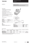
Technical Design-in Guide
5
12
5
12
3
c
.
Table of Contents
Table of contents
Description . . . . . . . . . . . . . . . . . . . . . . . . . . . . . . . . . . . . . . . . . . . . . . . . . . . . . . . . . . . . . . . . . . . . . . . . . . . 4
Complete system solution . . . . . . . . . . . . . . . . . . . . . . . . . . . . . . . . . . . . . . . . . . . . . . . . . . . . . . . . . . . . . . . . . . . . .
Creative freedom . . . . . . . . . . . . . . . . . . . . . . . . . . . . . . . . . . . . . . . . . . . . . . . . . . . . . . . . . . . . . . . . . . . . . . . . . . . .
Warm and pleasant light . . . . . . . . . . . . . . . . . . . . . . . . . . . . . . . . . . . . . . . . . . . . . . . . . . . . . . . . . . . . . . . . . . . . . .
Outstanding cost effectiveness . . . . . . . . . . . . . . . . . . . . . . . . . . . . . . . . . . . . . . . . . . . . . . . . . . . . . . . . . . . . . . . . .
4
5
5
5
Summary of the chapters . . . . . . . . . . . . . . . . . . . . . . . . . . . . . . . . . . . . . . . . . . . . . . . . . . . . . . . . . . . . . . . . 6
System overview . . . . . . . . . . . . . . . . . . . . . . . . . . . . . . . . . . . . . . . . . . . . . . . . . . . . . . . . . . . . . . . . . . . . . . . . . . . .
Mechanical aspects . . . . . . . . . . . . . . . . . . . . . . . . . . . . . . . . . . . . . . . . . . . . . . . . . . . . . . . . . . . . . . . . . . . . . . . . . .
Electrical aspects . . . . . . . . . . . . . . . . . . . . . . . . . . . . . . . . . . . . . . . . . . . . . . . . . . . . . . . . . . . . . . . . . . . . . . . . . . . .
Optical aspects . . . . . . . . . . . . . . . . . . . . . . . . . . . . . . . . . . . . . . . . . . . . . . . . . . . . . . . . . . . . . . . . . . . . . . . . . . . . .
Thermal aspects . . . . . . . . . . . . . . . . . . . . . . . . . . . . . . . . . . . . . . . . . . . . . . . . . . . . . . . . . . . . . . . . . . . . . . . . . . . .
6
6
6
6
6
System overview . . . . . . . . . . . . . . . . . . . . . . . . . . . . . . . . . . . . . . . . . . . . . . . . . . . . . . . . . . . . . . . . . . . . . . 7
System versions . . . . . . . . . . . . . . . . . . . . . . . . . . . . . . . . . . . . . . . . . . . . . . . . . . . . . . . . . . . . . . . . . . . . . . . . . . . . 7
Converters . . . . . . . . . . . . . . . . . . . . . . . . . . . . . . . . . . . . . . . . . . . . . . . . . . . . . . . . . . . . . . . . . . . . . . . . . . . . . . . . . 7
Operating functions . . . . . . . . . . . . . . . . . . . . . . . . . . . . . . . . . . . . . . . . . . . . . . . . . . . . . . . . . . . . . . . . . . . . . . . . . . 8
Type codes and versions . . . . . . . . . . . . . . . . . . . . . . . . . . . . . . . . . . . . . . . . . . . . . . . . . . . . . . . . . . . . . . . . . . . . . 9
Versions . . . . . . . . . . . . . . . . . . . . . . . . . . . . . . . . . . . . . . . . . . . . . . . . . . . . . . . . . . . . . . . . . . . . . . . . . . . . . . . . . . 10
Converter matrix . . . . . . . . . . . . . . . . . . . . . . . . . . . . . . . . . . . . . . . . . . . . . . . . . . . . . . . . . . . . . . . . . . . . . . . . . . . 11
Standards and directives . . . . . . . . . . . . . . . . . . . . . . . . . . . . . . . . . . . . . . . . . . . . . . . . . . . . . . . . . . . . . . . . . . . . . 14
Mechanical aspects . . . . . . . . . . . . . . . . . . . . . . . . . . . . . . . . . . . . . . . . . . . . . . . . . . . . . . . . . . . . . . . . . . . 17
Installation . . . . . . . . . . . . . . . . . . . . . . . . . . . . . . . . . . . . . . . . . . . . . . . . . . . . . . . . . . . . . . . . . . . . . . . . . . . . . . . . 17
Dimensional drawings . . . . . . . . . . . . . . . . . . . . . . . . . . . . . . . . . . . . . . . . . . . . . . . . . . . . . . . . . . . . . . . . . . . . . . . 24
Electrical aspects . . . . . . . . . . . . . . . . . . . . . . . . . . . . . . . . . . . . . . . . . . . . . . . . . . . . . . . . . . . . . . . . . . . . . 28
Electrical safety . . . . . . . . . . . . . . . . . . . . . . . . . . . . . . . . . . . . . . . . . . . . . . . . . . . . . . . . . . . . . . . . . . . . . . . . . . . .
Electrical safety and connection . . . . . . . . . . . . . . . . . . . . . . . . . . . . . . . . . . . . . . . . . . . . . . . . . . . . . . . . . . . . . . .
Electrical connections . . . . . . . . . . . . . . . . . . . . . . . . . . . . . . . . . . . . . . . . . . . . . . . . . . . . . . . . . . . . . . . . . . . . . . .
Connections on the LED control gear . . . . . . . . . . . . . . . . . . . . . . . . . . . . . . . . . . . . . . . . . . . . . . . . . . . . . . . . . . .
Wiring diagrams . . . . . . . . . . . . . . . . . . . . . . . . . . . . . . . . . . . . . . . . . . . . . . . . . . . . . . . . . . . . . . . . . . . . . . . . . . . .
28
29
30
31
32
Optical aspects . . . . . . . . . . . . . . . . . . . . . . . . . . . . . . . . . . . . . . . . . . . . . . . . . . . . . . . . . . . . . . . . . . . . . . 35
Colour spectrum . . . . . . . . . . . . . . . . . . . . . . . . . . . . . . . . . . . . . . . . . . . . . . . . . . . . . . . . . . . . . . . . . . . . . . . . . . . 35
Beam characteristics . . . . . . . . . . . . . . . . . . . . . . . . . . . . . . . . . . . . . . . . . . . . . . . . . . . . . . . . . . . . . . . . . . . . . . . . 38
Thermal aspects . . . . . . . . . . . . . . . . . . . . . . . . . . . . . . . . . . . . . . . . . . . . . . . . . . . . . . . . . . . . . . . . . . . . . 41
Cooling the modules . . . . . . . . . . . . . . . . . . . . . . . . . . . . . . . . . . . . . . . . . . . . . . . . . . . . . . . . . . . . . . . . . . . . . . . . 41
Ordering information and sources . . . . . . . . . . . . . . . . . . . . . . . . . . . . . . . . . . . . . . . . . . . . . . . . . . . . . . . . 45
Article numbers . . . . . . . . . . . . . . . . . . . . . . . . . . . . . . . . . . . . . . . . . . . . . . . . . . . . . . . . . . . . . . . . . . . . . . . . . . . .
Product application and partners . . . . . . . . . . . . . . . . . . . . . . . . . . . . . . . . . . . . . . . . . . . . . . . . . . . . . . . . . . . . . . .
Partners . . . . . . . . . . . . . . . . . . . . . . . . . . . . . . . . . . . . . . . . . . . . . . . . . . . . . . . . . . . . . . . . . . . . . . . . . . . . . . . . . .
Tridonic sales organisation . . . . . . . . . . . . . . . . . . . . . . . . . . . . . . . . . . . . . . . . . . . . . . . . . . . . . . . . . . . . . . . . . . .
Additional information . . . . . . . . . . . . . . . . . . . . . . . . . . . . . . . . . . . . . . . . . . . . . . . . . . . . . . . . . . . . . . . . . . . . . . .
Technical Design-in Guide TALEXXengine STARK LLE | 11-2013 | 2.2 | en
3 / 53
45
46
49
53
53
c
.
Introduction
Description
A new era has dawned with TALEXX-LED. Now, high-quality light and optimum efficiency are no longer mutually
exclusive. The versatile system solutions from Tridonic provide the basis for outstanding lighting designs that are
future-proof, economical and eco-friendly in a wide range of applications.
LEDs come into their own in offices and educational institutions, in industry as well as technical working environments.
When designing LED lighting, there are certain differences compared to designs with conventional light sources. This
design guide has been written to help you understand these differences. It answers all the most important questions
you may have, such as on the right mechanical design, thermal management and optical conditions.
Complete system solution
LEDs offer major advantages in terms of general lighting: They are versatile, highly energy efficient and virtually
maintenance free. With TALEXXengine STARK LLE you get a complete system solution from a single source
comprising perfectly harmonised components: TALEXXmodule STARK LLE and TALEXXconverter.
The TALEXXengine STARK LLE offers impressive advantages:
LED system solution with outstanding system efficiency of up to 112 lm/W consisting of a linear LED module
and LED control gear
Small colour tolerances of up to MacAdam 3
Luminous flux of approximately 1,250 lumen per LED module (hot lumen measurement at 65°C for technical
specification under real conditions)
High colour rendering (CRI >80)
Colour temperatures of 3,000 K, 4,000 K and 5,000 K
Option of combining multiple products, also with TALEXXengine STARK QLE
Emergency lighting compatible LED control gear in dimmable and non-dimmable versions
Long lamp life of up to 50,000 hours
Compliance with the mechanical and electrical standards of the luminaire industry
I NOTICE
All information in this guide has been produced with the utmost care. However, the guide is subject to change
without notice. Errors and omission excepted. Tridonic does not accept liability for possible damage resulting from
the use of this guide. The latest version of this guide can be found at led.tridonic.com or from your sales partner.
Technical Design-in Guide TALEXXengine STARK LLE | 11-2013 | 2.2 | en
4 / 53
c
.
Introduction
Creative freedom
This linear LED module is virtually predestined for combination. When lined up lengthwise, narrow strip lighting is
created and, in combination with the square sister product, TALEXXengine STARK QLE, any number of customised
luminaire designs can be realised. Up to six LED modules can be operated with just one LED control gear.
The LED modules can be quickly wired up thanks to the push-in terminals.
This makes it extremely easy to both integrate efficient LED technology into existing luminaire designs and also realise
new design ideas - irrespective of the optics as the TALEXXengine STARK LLE is suitable for all systems, from louvre
to diffuser lights.
Warm and pleasant light
With excellent colour rendering and a choice of warm and neutral white colour temperatures, the LED system solution
is a high-quality replacement for T5 and T8 fluorescent lamps - the result is pleasant and feel-good lighting.
Outstanding cost effectiveness
Compared to light installations with conventional lamps, TALEXX-LED reduces energy consumption by up to 40
percent. Its long service life means significantly lower maintenance and repair costs.
Experience a new world of lighting with TALEXX-LED!
...
Technical Design-in Guide TALEXXengine STARK LLE | 11-2013 | 2.2 | en
5 / 53
c
.
Summary of the chapters
Summary of the chapters
To make it easier to find your way around the Design-in Guide, we have grouped the information on the
TALEXXengine STARK LLE system into chapters: The guide begins with a system overview in which the different
versions of the system are presented. The mechanical, electronic, optical and thermal aspects of the components are
then described. At the end of the Design-in Guide, you will find ordering information and sources.
System overview
The TALEXXengine STARK LLE system is available in the versions LLE Classic, LLE24 Classic and LLE24. The
relevant components can be clearly assigned by their type codes.
Mechanical aspects
Depending on the particular situation, the LED control gear can be installed in the luminaire casing (inbuilt) or outside
the casing (remote).
Dimensional drawings and installation instructions will help you to take account of the requirements of the particular
situation.
Electrical aspects
The TALEXXmodule STARK LLE can be combined with a variety of LED control gear.
Electrical safety aspects, connection options, the connection between the LED control gear and the power supply and
the connections are described and shown in the relevant wiring diagrams.
Optical aspects
The overall efficiency of the system is improved by choosing a reflector with suitable optical properties (e.g. beam
angle) and dimensions. This chapter provides information on beam characteristics and illumination strength.
Thermal aspects
The system modules are designed for operation with a passive heat sink and, to this end, can be mounted directly on a
suitable heat sink. Information on heat sinks and temperature measurement is summarised in this section.
Ordering information and sources
Information on ordering heat sinks as well as where heat sinks, reflectors and accessories can be sourced can be
found at the end of this document.
...
Technical Design-in Guide TALEXXengine STARK LLE | 11-2013 | 2.2 | en
6 / 53
c
.
System Overview
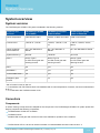
System overview
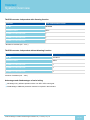
System versions
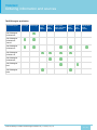
The TALEXXengine STARK LLE system is available in the following versions
Properties and
functions
TALEXXengine STARK
LLE CLASSIC
TALEXXengine STARK
LLE24 CLASSIC
TALEXXengine STARK
LLE24 CLASSIC EM
Colour temperature
3,000 K and 4,000 K
3,000 K, 4,000 K and 5,000
K
3,000 K und 4,000 K
Luminous flux*
1,250 lm or 1,190 lm
1,300 lm, 1,360 lm, 1,370
lm
1,300 lm, 1,360 lm, 240 lm,
250 lm
Colour rendering /
colour tolerance
CRI > 80 / MacAdam 4
SDCM
Ra > 80 / MacAdam 3
SDCM
Ra > 80 / MacAdam 3 SDCM
System efficiency**
98 lm/W
108 lm/W
107 lm/W
DALI***
Device Type 6
for LED control gear with
dimming function
Device Type 6
for LED control gear with
dimming function
Device Type 6
for LED control gear with
dimming function
DSI***
yes
yes
yes
switchDIM***
yes
yes
yes
corridorFUNCTION***
yes
yes
yes
Emergency light
function
no
no
yes
* with a forward current of 350 mA
** in combination with TALEXXconverter LCAI 080/0350 with a colour temperature of 4,000 K, hot lumen measurement
at 65 °C
*** in combination with TALEXXconverter LCAI
Converters
Components
A uniform naming concept has been adopted for the components. The TALEXXengine STARK LLE system (linear LED
Engine) comprises the following components:
TALEXXmodule STARK LLE CLASSIC
TALEXXconverter
Suitable LED control gear with various functions are available for operation of the modules.
The EM Power LED 2-4 W can be used for operation of a decentralised emergency light function. A
Technical Design-in Guide TALEXXengine STARK LLE | 11-2013 | 2.2 | en
7 / 53
c
.
System Overview
The EM Power LED 2-4 W can be used for operation of a decentralised emergency light function. A
TALEXXmodule is
then operated with minimal luminious flux.
I NOTICE
Information on components for emergency light functions can be found on the Tridonic homepage led.tridonic.com a
nd the respective product pages.
Efficiency of the modules
The high efficiency of the TALEXXmodule STARK LLE results not only in energy savings but also in a reduction in the
thermal load. This means that more compact luminaires can be designed.
Area of application
The components of the TALEXXengine STARK LLE system are suitable for indoor applications.
TALEXXengine STARK LLE is mostly used in protection class I luminaires.
Operating functions
DALI
DALI functionality enables the modules to be digitally controlled via the DALI signal (16-bit Manchester Code). The
possible functions depend on the controller used.
The minimum and maximum dimming levels can be programmed.
The control input is protected against polarity reversal and accidental connection to mains voltage up to 264 V AC.
The control line must be installed in accordance with the relevant directives on low voltage.
DSI
The DSI interface (Digital Serial Interface) allows luminaires to be controlled via a separate line, irrespective of the
power supply cabling. If the room layout is changed, only the control line needs to be rerouted, the load line can be left
unchanged. Switching on and off is controlled via the digital interface.
The low-voltage cable of the digital interface is polarity-free and can therefore be connected with either polarity to the
DSI connection of the LED control gear.
TALEXXconverters with integrated DSI function are able to specify a minimum dimming value, maximum brightness
and an emergency lighting value for all the connected operating devices in a control circuit. Using a digital interface
ensures a consistent lighting level from the first to the last luminaire.
However, in contrast to DALI, the individual luminaires cannot be addressed separately.
Technical Design-in Guide TALEXXengine STARK LLE | 11-2013 | 2.2 | en
8 / 53
c
.
System Overview
switchDIM
The integrated switchDIM function enables a standard switch for dimming and switching to be connected directly.
Pressing briefly on the switch (< 0.6 s) switches the LED control gear on or off. The last dimming value set will be
recalled when the LED control gear is switched on.
Pressing the button for an extended period (> 0.6 s) serves to dim the connected module. The dimming direction
(up/down) is changed when the switch is operated again.
Hold down the switch for about 10 seconds to synchronise all the connected devices to a dimming value of 50%. This
prevents the LED control gear from starting at different dimming values or operating in the opposite dimming direction
(e.g. with retrofit installations).
½ CAUTION!
Switches with glow lamps affect the switchDIM function and should therefore not be used for this purpose.
corridorFUNCTION
TALEXXconverters one4all together with commercially available motion detectors enable the corridorFUNCTION:
Presence-controlled lighting systems can be programmed without an additional controller so that the light is not
switched off when no one is present and, instead, dimmed to a minimal level - and possibly only switched off
completely after a preset period of time.
Type codes and versions
Type code for modules
The following type code is used to unambiguously identify the modules:
Type code for modules using STARK LLE 24 1250 830 CLA as an example
Designation
STARK
LLE
24
1250
8
30
CLA
Meaning
Product
Form
Width
Luminous flux
in lm
Ra > 80
Colour temperature
3,000 K
Version
Type code for LED control gear
The following type code is used to unambiguously identify the LED control gear:
Technical Design-in Guide TALEXXengine STARK LLE | 11-2013 | 2.2 | en
9 / 53
c
.
System Overview
Type code for LED control gear using LCI 080/0350 ....as an example
Designation
LCI
080
Meaning
LED LED control gear,
constant current
non-dimmable
Power in W
/
0350
Current in mA
Type code for LED control gear using LCAI 080/0350 ...as an example
Designation
LCAI
080
Meaning
LED LED control gear,
constant current
dimmable
Power in W
/
0350
Current in mA
The precise type designation for the LED control gear is given on the type plate of the LED control gear.
I NOTICE
Please note the system combinations with the matching components on the following pages.
Ordering information on the components can be found at the end of this document.
Versions
TALEXXengine STARK LLE
The TALEXXengine STARK LLE system is an attractive entrylevel solution for general LED illumination. Depending on
the application TALEXXconverters with and without a dimming function are available.
Characteristics
Colour temperature 3,000 K, 4,000 K or 5,000 K
Colour rendering index CRI > 80
Lumen values of approximately 1,250 lm
Low colour tolerance of up to MacAdam 3 SDCM
System efficiency of up to 112 lm/W with high energy savings and short payback time
Control functions
ON/OFF via network with LED control gear without dimming function
DALI, DSI, corridorFUNCTION and switchDIM with LED control gear with dimming function
Technical Design-in Guide TALEXXengine STARK LLE | 11-2013 | 2.2 | en
10 / 53
c
.
System Overview
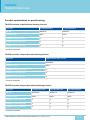
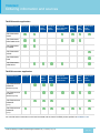
Converter matrix
Possible combinations for serial wiring
TALEXXconverter in-built with dimming function
Converter
LCAI 080/350 one4all
Art. No.
86459392
Protection class
NON SELV
STARK-LLE-1250...*
4-6
STARK-LLE-24-1250...*
4-6
STARK-LLE-1250-EM...*
4-6
* Number of modules (min. - max.)
TALEXXconverter in-built without dimming function
Converter
LCI 080/350 I010
LCCI 016/035 Q010
Art. No.
86459366
86459213
Protection class
NON SELV
SELV
STARK-LLE-1250-830-CLA*
4-6
1
STARK-LLE-1250-840-CLA*
4-6
1
STARK-LLE-1250-850-CLA*
4-6
1
* Number of modules (min. - max.)
Technical Design-in Guide TALEXXengine STARK LLE | 11-2013 | 2.2 | en
11 / 53
c
.
System Overview
TALEXXconverter independent with dimming function
Converter
LCAI 015/0350 A020 one4all
Art. No.
86458899
Protection class
SELV
STARK-LLE-1250-830-CLA*
1
STARK-LLE-1250-840-CLA*
1
STARK-LLE-1250-850-CLA*
1
* Number of modules (min. - max.)
TALEXXconverter independent without dimming function
Converter
LCI 015/0350 E020
Art. No.
24166312
Protection class
SELV
STARK-LLE-1250-830-CLA*
1
STARK-LLE-1250-840-CLA*
1
STARK-LLE-1250-850-CLA*
1
*Number of modules (min. - max.)
Advantages and disadvantages of serial wiring
Advantage: Very efficient operation with a non-SELV LED control gear
Disadvantage: Additional protection measure is required in the luminaire
Technical Design-in Guide TALEXXengine STARK LLE | 11-2013 | 2.2 | en
12 / 53
c
.
System Overview
Possible combinations for parallel wiring
TALEXXconverter in-built without dimming function
Converter
LCI 050/1050 R010
LCI 055/1400 R010
Art. No.
86459216
86459217
Protection class
SELV
SELV
STARK-LLE-1250-830-CLA**
3
4
STARK-LLE-1250-840-CLA**
3
4
STARK-LLE-1250-850-CLA**
3
4
** Number of modules
TALEXXconverter independent with dimming function
Converter
LCAI 030/0700 A120 one4all
Art. No.
86458900
Protection class
SELV
STARK-LLE-1250-830-CLA**
2
STARK-LLE-1250-840-CLA**
2
STARK-LLE-1250-850-CLA**
2
** Number of modules
TALEXXconverter independent without dimming function
Converter
LCI 050/1050 T020
LCI 055/1400 T020
LCI 030/0700 E020
Art. No.
86459218
86459219
24166314
Protection class
SELV
SELV
SELV
STARK-LLE-1250-830-CLA**
3
4
2
STARK-LLE-1250-840-CLA**
3
4
2
STARK-LLE-1250-850-CLA**
3
4
2
** Number of modules
Technical Design-in Guide TALEXXengine STARK LLE | 11-2013 | 2.2 | en
13 / 53
c
.
System Overview
Advantages and disadvantages of parallel wiring
Advantages: SELV level protection class Several modules can be operated in parallel with just one LED control
gear
Disadvantage: Possible reduction in service life (if a module fails or a cable breaks, the current of the other
modules increases), tolerance-related differences in brightness as well as larger amount of cabling.
Standards and directives
Standards and directives for modules
The following standards and directives were taken into consideration in designing and manufacturing the modules:
CE
2006/95/EG
Low-voltage directive: Directive relating to electrical equipment for use within certain voltage limits
2004/108/EG
EMC* directive:
Directive relating to electromagnetic compatibility
RoHS
2002/95/EC
RoHS*-Directive: Directive on the restriction of the use of certain hazardous substances in electrical
and electronic equipment
* RoHS: Restriction of (the use of certain) hazardous substances
Safety
DIN IEC 62031:2008
Safety requirements for LED modules
EN 60598-1:2008 und A11:2009
General requirements and tests for luminaires
EN 60598-2-2:1996 und A1:1997
Luminaires - Part 2. Special requirements;
Main section 2: Recessed luminaires
EN 62471:2008
Photo-biological safety of lamps and lamp systems
Technical Design-in Guide TALEXXengine STARK LLE | 11-2013 | 2.2 | en
14 / 53
c
.
System Overview
Safety and performance
EN 61347-1:2009
General and safety requirements
EN 61347-2-13:2007
Special requirements for dc and ac powered electronic operating equipment for
LED modules
EN 62384:2007 IEC 62384
A1:2009
Operational requirements
Energy labelling
EU Regulation No: 874/2012
"Energy labelling of electrical lamps and luminaires"
Standards and directives for LED control gear
The following standards and directives were taken into consideration in designing and manufacturing the LED control
gear:
EMI
EN 55015 2008
Limit values measurement methods for radio interference properties of electrical
lighting equipment and similar electrical devices
EN 61000-3-2:2005 A1:
2008 und A2:2009
Limit values for harmonic currents (equipment input current < 16 A per conductor)
EN 61000-3-3:2005
Limit values for voltage fluctuations and flicker in low-voltage systems for equipment
with an input current < 16 A per conductor that are not
subject to any special connection conditions
EN 61547:2001
EMC* requirements
* EMC: Electromagnetic compatibility
Safety
EN 50172 2005
Safety lighting systems
Technical Design-in Guide TALEXXengine STARK LLE | 11-2013 | 2.2 | en
15 / 53
c
.
System Overview
DALI
IEC 62386-101:2009
General requirements, system
IEC 62386-102:2009
General requirements, controller
IEC 62386-207:2009
Special requirements, controller; LED modules
...
Technical Design-in Guide TALEXXengine STARK LLE | 11-2013 | 2.2 | en
16 / 53
c
.
Mechanical Aspects
Mechanical aspects
Installation
Installation details
I NOTICE
EOS/ESD safety guidelines
The device/module contains components that are sensitive to electrostatic discharge and may only be installed in
the factory and on site if appropriate EOS/ESD protection measures have been taken. No special measures need be
taken for devices/modules with enclosed casings (contact with the pc board not possible), just normal installation
practice.
Please note the requirements set out in the document EOS/ESD guidelines (Guideline_EOS_ESD.pdf) at:
www.tridonic.com/com/en/technical-docs.asp
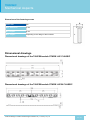
Installation example with TALEXXconverter and serial wiring
Installation version IN-BUILT serial wiring with
TALEXXconverter LCAI 80 W 350 mA one4all
Surface-mounting version REMOTE with serial wiring
with TALEXXconverter LCI 15 W 350 mA
Technical Design-in Guide TALEXXengine STARK LLE | 11-2013 | 2.2 | en
17 / 53
c
.
Mechanical Aspects
Installation example with TALEXXconverter and parallel wiring
Installation version IN-BUILT parallel wiring with
TALEXXconverter LCI 50 W 1050 mA
Surface-mounting version REMOTE with parallel wiring with
TALEXXconverter LCI 55 W 1400 mA
Installation details
Depending on the particular situation, the LED control gear can be installed in the luminaire casing (in-built) or outside
the casing (remote).
Terminals with push button for
quick and easy wiring
Perfectly uniform light, even if several LED
modules are used together
Beveled Edges for discreet wiring
and easy installation
Notes on installation
Depending on the installation situation for the LED control gear and modules, the following requirements must be met:
Sufficient distance to active conducting materials
Sufficient strain relief when the LED control gear cover is closed
Sufficient cooling of the modules
(the max. temperature at the tc point must not be exceeded)
Unrestricted exit of light from the modules
The module's push-in terminals allow easy wiring. They can be released via the trigger
Technical Design-in Guide TALEXXengine STARK LLE | 11-2013 | 2.2 | en
18 / 53
c
.
Mechanical Aspects
I NOTICE
Detailed information on the thermal connection and the position of the tc point is given at "Thermal aspects".
Protection measures against damage
Mechanical stress
TALEXX modules contain electronic components that are sensitive to mechanical stress. Such stress should be kept to
an absolute minimum. In particular the following mechanical stresses should be avoided as these may cause
irreversible damage:
Pressure
Bending stress
Drilling,
Milling,
Breaking,
Sawing,
and similar mechanical processing.
Compressive stresses
The components of the TALEXX modules (circuit boards, glob-top, lenses, electronic components etc.) are sensitive to
compressive stresses. The components must not be exposed to compressive stresses.
If glass or Plexiglas shields are used make sure that pressure is not exerted on the glob-top.
Only touch the TALEXX modules at the edges
correct (left) and incorrect (right)
Bending stress
Bending the circuit board of a TALEXX module by more than 3 % along its length may damage the product and is
therefore not permitted. 3 % corresponds for example to 6 mm for a 200 mm long module.
Max. bending stress for LED strip modules
Technical Design-in Guide TALEXXengine STARK LLE | 11-2013 | 2.2 | en
19 / 53
c
.
Mechanical Aspects
Chemical compatibility
LED modules can be damaged by other materials, if these materials have certain chemical properties. The cause for
these damages are different gaseous compounds, which penetrate into the encapsulant of the LED and thereby attack
the encapsulant, the color conversion phosphor or the LED chips and can affect the electrical contacts or the substrate.
Application areas for chemical substances
The following are known areas in which chemical substances are used:
use of protective coating in applications with high relative humidity (outdoor applications),
encapsulation of LED modules,
cementing of LED modules,
sealing of luminaires.
The following materials must be checked for their safety:
All components and auxiliaries used in the assembly of the luminaire:
» Solvents of adhesives and coatings
» Other so-called VOC ("volatile organic compounds")
All other additional substances present in the atmosphere:
» Outgassing of adhesives, sealants and coatings
» Cleaning agents and processing aids (e.g. cutting oils and drilling coolants)
I NOTICE
Contact your LED manufacturer for questions about the materials used and possible interactions and risks.
Putting together a "safe list" is not possible due to the complexity of the topic. The following table lists possible
contaminants for LED modules, the classes of compounds and examples of possible sources.
The list shows the most commonly used materials but does not claim to be complete.
Class of compounds
Chemical names
Occurs in
Acids
»
»
»
»
» cleaner
» cutting oils
Organic acids
» acetic acid
»
»
»
»
Alkalis
» ammonia
» amines
» sodium hydroxide
» detergents
» cleaner
hydrochloric acid
sulfuric acid
nitric acid
phosphoric acid
Technical Design-in Guide TALEXXengine STARK LLE | 11-2013 | 2.2 | en
RTV silicones
cutting oils
degreaser
adhesives
20 / 53
c
.
Mechanical Aspects
Organic solvents
»
»
»
»
ethers (e.g. glycol )
ketones (e.g. Methylethylketon )
aldehydes (e.g. formaldehyde)
aromatic hydrocarbons (e.g. xylene and
toluene)
»
»
»
»
cleaner
benzine
petroleum
paints and
varnishes
VOC (volatile organic
compounds)
»
»
»
»
acetate
acrylates
aldehydes
serve
» super glue
» all-purpose glue
» screw locking
varnish
» coatings
» paints and
varnishes
Mineral oils
» hydrocarbons
» machine oil
» lubricants
Vegetable oils and synthet. oils
» siloxanes
» fatty acids
» silicone oils
» linseed oil
» fats
Harder,
vulcanizer
» sulfur compounds
» seals
» sealants
» colors
Protection measures for the glob top material
The following guidelines must be observed to avoid damage to the glob-top:
Make sure that the chemicals used in LED applications are not solvent-based, condensation crosslinked or
acetate crosslinked (acetic acid). These give rise to reagents (e.g. solvent vapors, acetic acid) that may damage
LED modules or the encapsulant. This applies to chemicals that are used not in the immediate vicinity of the
modules (e.g. seals) and also to chemicals that come into direct contact with the modules (e.g. insulating
coatings, adhesives).
To ascertain the chemicals used and the type of cross linking a technical data sheet containing a list of
substances must be requested from the manufacturer.
Example of damaged encapsulant material, recognizable by the change of the chromaticity coordinates:
powerLED P211, original
powerLED P211, damaged by dissolver waste gas
Technical Design-in Guide TALEXXengine STARK LLE | 11-2013 | 2.2 | en
21 / 53
c
.
Mechanical Aspects
Protection measures in regards to sealing
The points above also apply to chemicals used for sealing luminaire casings. If however the LED module is not
installed in the luminaire until after the sealing compound has been completely cured (see relevant material
information) the above points can be ignored.
If the LED modules have already been installed in the luminaire, possible damage to the encapsulant can be reduced
to a minimum by ensuring adequate spacing (>10 cm) and ventilation (open casing and air circulation, extraction / fan)
during the curing process.
Protection measures in regards to cementing
To avoid damaging the LED modules you must not use any tools or exert any pressure on the electronic components
or the encapsulant.
If glass or Plexiglas shields are used make sure that pressure is not exerted on the encapsulant.
Only touch the LED modules at the edges
Instructions for cementing TALEXX modules
Preparation
Clean and durable bonding of two materials requires special attention.
The following cleaning agents are recommended:
Isopropanol / Water 50/50
Acetone
Heptane
Technical Design-in Guide TALEXXengine STARK LLE | 11-2013 | 2.2 | en
22 / 53
c
.
Mechanical Aspects
Important aspects
Carrier material
The carrier material must have adequate thermal conductivity (e.g. aluminium). The size of the cooling surface
depends on the power of the LEDs, among other things. For information on the cooling surface required, see the
appropriate product data sheet.
Adhesive material
The carrier material itself plays an important role in selecting the adhesive material. The crucial factors are the
coefficient of expansion and compatibility with the base material of the TALEXX module board (plastic or
aluminium). This must be checked in the application in terms of long-term stability, surface contamination and
mechanical properties.
Surface quality
The carrier material must be uncoated (thermal transport, adhesion) and level at the connection points.
Installation temperature
To achieve optimum adhesion we recommend you carry out this work at room temperature.
Duration, optimum adhesive strengths
Maximum adhesion is achieved within 48 hours at room temperature; the process is accelerated by heat. In
actual practice this means that at the maximum tc temperature (approx. 75-85 °C, product-specific) maximum
adhesion is reached after about 12 hours. During the curing period make sure that there is no tensile load on the
adhesive connection of the TALEXX module.
Additional information
TALEXX modules must not be stuck and restuck time and again without replacing the adhesive tape. Damaged
adhesive tapes must be completely removed and replaced by new tapes.
Packaging and transport
TALEXX products from Tridonic are delivered in appropriate packaging. The packaging provides special protection
against mechanical damage and ESD (electrostatic discharge). If you need to transport TALEXX products you should
use this packaging.
Installation of the modules on the heat sink
The LED modules are mounted onto a heat sink with 2 screws per module. For optimal thermical connection it is
recommended to use all fastening holes (e.g. 5 screws for the LLE24). In order not to damage the modules only
rounded head screws and an additional plastic flat washer should be used.
Suitable screws should be selected on the basis of the following dimensions:
Technical Design-in Guide TALEXXengine STARK LLE | 11-2013 | 2.2 | en
23 / 53
c
.
Mechanical Aspects
Dimensions of the fastening screws
Screw size
M3
Max. diameter D
7 mm
Min. length L
5 mm
Max. length L
depending on the design of the luminaire
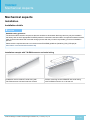
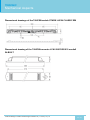
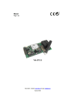
Dimensional drawings
Dimensional drawings of the TALEXXmodule STARK LLE CLASSIC
Dimensional drawings of the TALEXXmodule STARK LLE24 CLASSIC
Technical Design-in Guide TALEXXengine STARK LLE | 11-2013 | 2.2 | en
24 / 53
c
.
Mechanical Aspects
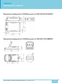
Dimensional drawings of the TALEXXmodule STARK LLE24 CLASSIC EM
Dimensional drawing of the TALEXXconverter LCAI 080/0350 I010 one4all
IN-BUILT
Technical Design-in Guide TALEXXengine STARK LLE | 11-2013 | 2.2 | en
25 / 53
c
.
Mechanical Aspects
Dimensional drawing of the TALEXXconverter LCI 055/1400 R010 IN-BUILT
Dimensional drawing of the TALEXXconverter LCI 050/1050 T020 REMOTE
Technical Design-in Guide TALEXXengine STARK LLE | 11-2013 | 2.2 | en
26 / 53
c
.
Mechanical Aspects
Dimensions of further TALEXXconverters
Type
LxWxH
LCAI 015/0350 A020 one4all
167 x 42 x 31 mm
LCAI 016/0350 Q010 one4all
103 x 67 x 31 mm
LCAI 030/0700 A120 one4all
207 x 42 x 31 mm
LCI 015/0350 E020
165 x 43 x 30 mm
LCI 080/0350 I010
280 x 30 x 21 mm
LCI 030/0700 E020
141 x 43 x 30 mm
LCI 050/1050 R010
123 x 79 x 31 mm
LCI 055/1400 T020
160 x 82 x 34 mm
LCCI 016/0350 Q010
103 x 67 x 31 mm
EM powerLED 2W
127 x 30 x 21 mm
EM powerLED 2W
127 x 30 x 21 mm
I NOTICE
CAD data on these and other LED control gear can be downloaded from the Tridonic homepage www.tridonic.com a
nd the relevant product page.
...
Technical Design-in Guide TALEXXengine STARK LLE | 11-2013 | 2.2 | en
27 / 53
c
.
Electrical Aspects
Electrical aspects
Electrical safety
Basic classification of protection classes
Depending on the design of the luminaire, the requirements of different electrical protection classes are satisfied:
Luminaires in protection class III (also SELV which stands for Safety Extra Low Voltage) have such low
internal voltages that a shock current would be inconsequential. AC voltages with an effective value of up
to 50 V AC and direct currents up to 120 V DC are referred to as low voltage (also extra-low voltage and
weak current).
Protection class II (non-SELV) applies for luminaires with double insulation, with no protective earth,
between the mains circuit and the output voltage or metal casing. Even if the luminaires have electrically
conductive surfaces, thanks to their insulation they are protected against contact with other live parts.
Protection class I (non-SELV) applies for luminaires with basic insulation and protective earth. All the
electrically conductive casing components are connected via a protective conductor system which is at
earth potential.
Basic insulation of TALEXXmodule STARK LLE
The TALEXXmodul STARK LLE features basic insulation against earth, i.e., a clearance/creepage distance greater or
the same as 3 mm and can be directly assembled on an earthed metal part of the luminaire, also in operation with the
TALEXXconverter LCAI 80W 350mA.
Design measures for satisfying protection class requirements
Not all the components of the TALEXX STARK LLE system comply with the SELV standard. The voltages can thus be
greater than 120 V DC.
Luminaire with SELV level
When using the LED module STARK LLE CLASSIC in combination with a TALEXXconverter in protection class SELV,
the SELV level for the luminaire is achieved.
Thanks to SELV voltage, the luminaire can be replaced by an expert without risk.
Protection class II luminaires
When using a TALEXXconverter with NON-SELV level, the following measures are essential in order to achieve
protection class II:
Reinforced insulation between TALEXXmodule STARK LLE and the luminaire casing, e.g., by means of plastic
casing or an additional insulating foil between the luminaire casing and the module.
Reinforced insulation between the LED control gear and luminaire casing, e.g., by means of plastic casing
Use of double-insulated lines
Technical Design-in Guide TALEXXengine STARK LLE | 11-2013 | 2.2 | en
28 / 53
c
.
Electrical Aspects
Use of double-insulated lines
Protect all electrical contacts against mechanical contact, this can typically be achieved with optics which cannot
be removed
Protection class I luminaires
When using a TALEXXconverter with NON-SELV level, the following measures are essential in order to achieve
protection class I:
Use of metal casing for the luminaire
Assembly of the TALEXXmodule STARK LLE directly on the casing
Grounding of the LED control gear, TALEXXmodule STARK LLE and the luminaire itself
Protect all electrical contacts against mechanical contact, this can typically be achieved with optics which cannot
be removed
½ DANGER!
The following measures must be followed in order to avoid lifethreatening situations:
Electrical work on a luminaire with protection class I or II (non-SELV) must only be carried out by an electrically
skilled person.
The luminaire must be disconnected from the mains before starting work on it.
Check the luminaire for damage, if there are any signs of damage, the luminaire must be replaced.
Electrical safety and connection
Electrostatic safety and EMC protection
The LED modules are tested up to a voltage of 8 KV static discharging. Depending on the ambient conditions,
appropriate precautionary measures must be taken in order to avoid higher voltages, for example during production or
installation.
For good EMC conduct, the lines should be run separately from the mains connections and lines. The maximum
secondary line length on the terminals is 2 metres.
Technical Design-in Guide TALEXXengine STARK LLE | 11-2013 | 2.2 | en
29 / 53
c
.
Electrical Aspects
Electrical supply and selection of the LED control gear
½ CAUTION!
TALEXXmodules STARK LLE are not protected against overvoltages, overcurrents, overloads and short-circuit
currents!
Safe and reliable operation of the LED modules can only be guaranteed in conjunction with a LED control gear
which complies with the relevant standards.
When using a TALEXXconverter, the following protection is offered:
Short-circuit recognition
Overload recognition
Overtemperature switch-off
TALEXXmodules STARK LLE must be supplied by a constant current LED control gear. Operation with a constant
voltage LED control gear leads to irreversible damage to the modules! Wrong polarity can damage the
TALEXXmodules STARK LLE. If a wire breaks or a complete module fails in the case of parallel wiring, the current
passing through the other modules increases. This may reduce the service life considerably.
Electrical connections
TALEXXmodule STARK LLE CLASSIC connections
The LED control gear is connected to the power supply and the connections of the control lines and the LED module
via push-in and spring terminals:
Line cross-section and stripped length of the insulation on the LED module:
Permissible line cross-section: 0.4 - 0.75 mm²
Stripped length of the insulation 6 - 7 mm
Push-in terminal for solid conductors
Push-in terminal for solid conductors
Line cross-section on the LED control gear with spring terminal:
Permissible line cross-section: 0.5 - 1.5 mm²
Stripped length of the insulation 8.5 - 9.5 mm
Spring terminal for stranded wire with end splice or solid conductor
Technical Design-in Guide TALEXXengine STARK LLE | 11-2013 | 2.2 | en
30 / 53
c
.
Electrical Aspects
Spring terminal for stranded wire with end splice or solid conductor
Permissible line cross-sections and stripped insulation lengths of LED control gear with screw terminals can be found
in the respective LED control gear data sheets.
LED module wire preparation
Converter wire preparation
Spring terminal on the LED control gear
Connections on the LED control gear
Connections on the LED control gear for TALEXXmodules STARK LLE CLASSIC
Pin/Connection
Connection on the TALEXXconverter
Design
Protective earth or functional earth
Spring terminal
~
Power input
Spring terminal
~
Power input
Spring terminal
DA*
Control input DALI / DSI / switchDIM / corridor FUNCTION
Spring terminal
DA*
Control input DALI / DSI / switchDIM / corridor FUNCTION
Spring terminal
+LED
TALEXXmodule STARK LLE CLASSIC
Spring terminal
-LED
TALEXXmodule STARK LLE CLASSIC
Spring terminal
* only with LED control gear with the corresponding functionality
Technical Design-in Guide TALEXXengine STARK LLE | 11-2013 | 2.2 | en
31 / 53
c
.
Electrical Aspects
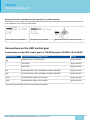
Wiring diagrams
Wiring diagram for TALEXXengine STARK LLE CLASSIC with serial wiring and
switchDIM
The wiring diagram shows serial wiring on a LED control gear with dimming function and 4 modules of type
TALEXXmodule STARK LLE CLASSIC as well as connection of the LED control gear to the power supply and direct
connection of a commercially available push to make switch.
Wiring diagram for TALEXXengine STARK LLE CLASSIC with serial wiring
The wiring diagram shows serial wiring on a LED control gear with 4 modules of type TALEXXmodule STARK LLE
CLASSIC as well as connection of the LED control gear to the power supply.
Technical Design-in Guide TALEXXengine STARK LLE | 11-2013 | 2.2 | en
32 / 53
c
.
Electrical Aspects
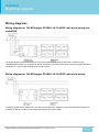
Wiring diagram for TALEXXengine STARK LLE CLASSIC with parallel wiring and
switchDIM
The wiring diagram shows parallel wiring between a LED control gear with dimming function and 2 modules of type
TALEXXmodule STARK LLE CLASSIC as well as connection of the LED control gear to the power supply and direction
connection of a commercially available push to make switch.
With parallel wiring tolerance-related differences in brightness are possible. If one module fails, the remaining modules
may be overloaded.
Wiring diagram for TALEXXengine STARK LLE CLASSIC with parallel wiring
The wiring diagram shows parallel wiring between a LED control gear and 3 modules of type TALEXXmodule STARK
LLE CLASSIC as well as connection of the LED control gear to the power supply.
Technical Design-in Guide TALEXXengine STARK LLE | 11-2013 | 2.2 | en
33 / 53
c
.
Electrical Aspects
I NOTICE
With parallel wiring tolerance-related differences in brightness are possible. If one module fails, the remaining
modules may be overloaded.
Wiring diagram for TALEXXengine STARK LLE CLASSIC and STARK LLE
CLASSIC EM
The wiring diagram shows connection between a LED control gear and 4 modules with serial wiring, of which 3
modules are of type TALEXXmodule STARK LLE CLASSIC and 1 of type TALEXXmodule STARK LLE EM CLASSIC
with emergency light function. The emergency light module is additionally operated by an emergency light supply
device.
Furthermore, connection of the LED control gear to the power supply / charger of the emergency light supply device is
shown.
...
Technical Design-in Guide TALEXXengine STARK LLE | 11-2013 | 2.2 | en
34 / 53
c
.
Optical Aspects
Optical aspects
Colour spectrum
Light colours
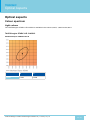
The TALEXXengine STARK LLE CLASSIC is available in the colours 3,000 K, 4,000 K and 5,000 K.
TALEXXengine STARK LLE CLASSIC
MacAdam Ellipse: 4SDCM 3.000 K
Centre
x0
y0
0.4344
0.4032
Technical Design-in Guide TALEXXengine STARK LLE | 11-2013 | 2.2 | en
35 / 53
c
.
Optical Aspects
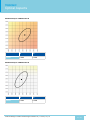
MacAdam Ellipse: 4SDCM 4.000 K
Centre
x0
y0
0.3828
0.3803
TALEXXengine STARK LLE24
MacAdam Ellipse: 3SDCM 3.000 K
Centre
x0
y0
0.4344
0.4032
Technical Design-in Guide TALEXXengine STARK LLE | 11-2013 | 2.2 | en
36 / 53
c
.
Optical Aspects
MacAdam Ellipse: 3SDCM 4.000 K
Centre
x0
y0
0.3828
0.3803
MacAdam Ellipse: 3SDCM 5.000 K
Centre
x0
y0
0.3422
0.3558
Technical Design-in Guide TALEXXengine STARK LLE | 11-2013 | 2.2 | en
37 / 53
c
.
Optical Aspects
Eye safety
Risk group
Evaluation
Actinic UV ES (200 - 400 nm)
Risk group 0*
Near UV EUVA (315 - 400 nm)
Risk group 0*
Blue light LB (300 - 700 nm)
Risk group 0*
Retina, thermal LR (380 - 1,400 nm)
Risk group 0*
IR radiation, eye EIR (780 - 3,000 nm)
Risk group 0*
* The evaluation of eye safety is based on EN 62471:2008 (photo-biological safety of lamps and lamp systems):
Risk-free (risk group 0): The LEDs do not pose any photo-biological risk.
Low risk (risk group 1): The LEDs pose a small risk because of normal limitations.
Medium risk (risk group 2): The LEDs pose a small risk because of reactions to bright light sources or thermal
discomfort.
High risk (risk group 3): The LEDs pose a risk even with just momentary or temporary exposure.
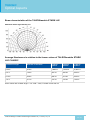
Beam characteristics
Reflector and diffusers
With STARK LLE CLASSIC modules, the luminaire can be produced with either a diffuser or reflectors. There must be
a minimum distance of 3 mm between the active parts and the conductive optical parts, e.g., reflector to the LED
module.
½ CAUTION!
When using reflectors in combination with a non-SELV LED control gear, protection against contact must be
ensured.
This is typically achieved with optics which cannot be removed over the module.
Technical Design-in Guide TALEXXengine STARK LLE | 11-2013 | 2.2 | en
38 / 53
c
.
Optical Aspects
Beam characteristics of the TALEXXmodule STARK LLE
Maximum relative light intensity lv/v
Average illuminance in relation to the lumen values of TALEXXmodule STARK
LLE CLASSIC
Installation height
Diameter of the beam
1,190 lm
3,000 K
1,250 lm
4,000 K
1,300 lm
5,000 K
0.25 m
0.79 m
1,828 lux
1,920 lux
2,000 lux
0.5 m
1.59 m
457 lux
480 lux
500 lux
0.75 m
2.38 m
203 lux
213 lux
220 lux
1.0 m
3.17 m
114 lux
120 lux
125 lux
All the values refer to Beam angle = 116° LOR = 100%, Forward current 350 mA
Technical Design-in Guide TALEXXengine STARK LLE | 11-2013 | 2.2 | en
39 / 53
c
.
Optical Aspects
Average illuminance in relation to the lumen values of TALEXXmodule STARK
LLE CLASSIC
Installation height
Diameter of the beam
1.190 lm
4.000 K
0.25 m
0.75 m
1,961 lux
0.5 m
1.49 m
490 lux
0.75 m
2.24 m
218 lux
1.0 m
2.99 m
123 lux
All the values refer to Forward current 300 mA
I NOTICE
To aid customised design and for optical simulation, Tridonic is happy to provide the modules' CAD data on request.
Sources of reflectors can be found at the end of this document.
...
Technical Design-in Guide TALEXXengine STARK LLE | 11-2013 | 2.2 | en
40 / 53
c
.
Thermical Aspects
Thermal aspects
Cooling the modules
Effect of cooling on the life of the modules
The modules of the TALEXXengine STARK LLE system have been designed for operation with a passive heat sink
and can be mounted directly on such a suitable heat sink.
The life of the module depends to a large extent on the operating temperature. The more that the operating
temperature can be reduced by cooling, the longer the expected life of the module. If the permitted operating
temperature is exceeded, however, the life of the module will be significantly reduced.
Operating time for TALEXXengine STARK LLE and TALEXXengine STARK LLE24
The table shows the operating time for different luminous flux at tc = 65 °C, 350 mA.
Luminous flux
Operating time STARK LLE
80 %
32,000 h
70 %
50,000 h
50 %
92,000 h
Luminous flux
Operating time STARK LLE24
80 %
30,000 h
70 %
60,000 h
50 %
100,000 h
I NOTICE
Please check the information on the operating temperature and the requirements for cooling in the module data
sheets.
...
Technical Design-in Guide TALEXXengine STARK LLE | 11-2013 | 2.2 | en
41 / 53
c
.
Thermical Aspects
Requirements for the heat sink
The modules must not be operated without a heat sink. The heat sinks must be dimensioned to provide adequate
cooling capacity.
The necessary Rth value is decisive when selecting a suitable heat sink. This value depends on the thermal power loss
of the module and the ambient temperature at which the module is to be operated. The R th value of the heat sink must
always be smaller than the required Rth value.
Ambient temperature (ta)
Rth, hs-a LLE
Cooling surface LLE
Rth, hs-a LLE24
Cooling surface LLE24
25 °C
3.4 K/W
100 cm2
5.1 K/W
131 cm2
35 °C
3.0 K/W
120 cm2
3.8 K/W
176 cm2
45 °C
2.3 K/W
250 cm2
2.5 K/W
268 cm2
55 °C
1.5 K/W
680 cm2
n.a.
n.a.
All the values refer to a maximum surface temperature tc = 65°C and 350 mA.
The actual cooling surface can deviate depending on the material, design, external influences and the installation
situation.
A thermal connection between TALEXXmodule STARK LLE and the heat sink using heat-conducting paste or
heat-conducting adhesive foil is essential.
Technical Design-in Guide TALEXXengine STARK LLE | 11-2013 | 2.2 | en
42 / 53
c
.
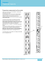
Thermical Aspects
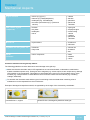
Temperature measurement on the module
There is a tc point on top of the module for checking the
temperature of the latter:
The temperature at the tc point can be measured with a
simple temperature probe. Since the underside of the
modules is made from anodised aluminium, any
measurements taken with an infra-red camera would lead
to inaccurate results.
In practice, thermocouples (e.g. B&B Thermotechnik,
K-type thermocouple) have proved successful. Such
thermocouples can be attached directly to the tc point with
heat-resistant adhesive tape or a suitable adhesive. The
measured values are recorded by an electronic
thermometer (e.g., "FLUKE 51", VOLTCRAFT K202 data
logger).
The maximum possible temperature must be determined
under worst-case conditions (ambient temperature,
installation of the luminaire) for the relevant application.
Before the measurement is taken, the luminaire should be
operated for at least 4 hours in a draught-free room.
The measurement must be taken in a steady thermal state
and in a draughtfree room.
tc point LLE24
tc point LLE
Technical Design-in Guide TALEXXengine STARK LLE | 11-2013 | 2.2 | en
43 / 53
c
.
Ordering information and sources
Temperature management of the LED control gear
Although the LED control gear have an integrated temperature management system, the requirements relating to
cooling of the LED control gear must also be taken into account. Unintentional automatic dimming at overtemperature,
for example, indicates inadequate cooling of the LED control gear.
The LED control gear temperature can be measured with a simple temperature probe at the t c point. The tc point of the
LED control gear is indicated by a sticker on the casing.
I NOTICE
Measurement conditions, sensors and handling are described in detail in standard EN 60598-1 "General
requirements and tests for luminaires".
Sources for suitable heat-conducting foil and pastes for thermal connection to a temperature probe are given at the
end of this documents.
Technical Design-in Guide TALEXXengine STARK LLE | 11-2013 | 2.2 | en
44 / 53
c
.
Ordering information and sources
Ordering information and sources
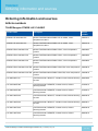
Article numbers
TALEXXengine STARK LLE CLASSIC
Product name
Description
Article
number
STARK LLE-1250-830-CLA
Module TALEXXmodule STARK LLE CLASSIC, colour
temperature 3,000 K
25000717
STARK LLE-1250-840-CLA
Module TALEXXmodule STARK LLE CLASSIC, colour
temperature 4,000 K
25000718
STARK-LLE24-1250-830-CLA
Module TALEXXmodule STARK LLE24, colour temperature
3,000 K
28000094
STARK-LLE24-1250-840-CLA
Module TALEXXmodule STARK LLE24, colour temperature
4,000 K
28000095
STARK-LLE24-1250-850-CLA
Module TALEXXmodule STARK LLE24, colour temperature
5,000 K
25000820
STARK-LLE24-1250-830-CLA-EM
Module TALEXXmodule STARK LLE24 EM, colour temperature
3,000 K
25000816
STARK-LLE24-1250-840-CLA-EM
Module TALEXXmodule STARK LLE24 EM, colour temperature
4,000 K
25000818
LCI 080/0350 I010
TALEXXconverter, IN-BUILT, constant current, without dimming
function
86459366
LCI 015/0350 E020
TALEXXconverter, REMOTE, constant current, without
dimming function
24166312
LCI 030/0700 E020
TALEXXconverter, REMOTE, constant current, without
dimming function
24166314
LCI 050/1050 R010
TALEXXconverter, IN-BUILT, constant current, without dimming
function
86459216
LCI 055/1400 R010
TALEXXconverter, IN-BUILT, constant current, without dimming
function
86459217
LCI 050/1050 T020
TALEXXconverter, REMOTE, constant current, without
dimming function
86459218
LCI 055/1400 T020
TALEXXconverter, REMOTE, constant current, without
dimming function
86459219
Technical Design-in Guide TALEXXengine STARK LLE | 11-2013 | 2.2 | en
45 / 53
c
.
Ordering information and sources
LCI 055/1400 R010
TALEXXconverter, IN-BUILT, constant current, without dimming
function
86459217
LCI 055/1400 T020
TALEXXconverter, IN-BUILT, constant current, without dimming
function
86459219
LCCI 016/0350 Q010
TALEXXconverter, IN-BUILT, adjustable output current
86459213
Suitable controllers
Tridonic offers a comprehensive range of DALI-compatible products. All the devices specified here support DALI
Device Type 6 and therefore guarantee effective use of TALEXXengine STARK LLE.
Product name
Artikelnummer
DALI M-Sensor
86458265
DALI SC
24034263
DALI MC
86458507
DALI Touchpanel
24035465
x-touchBOX
24138954
x-touchPANEL
24138990
DALI PS
24033444
DALI USB
24138923
I NOTICE
Go to led.tridonic.com for further emergency lighting products.
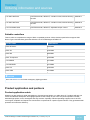
Product application and partners
Product application matrix
Whether you are looking for wide-area lighting or focused accent lighting, our wide range of T products will help you
create an individual atmosphere and highlight specific areas exactly as you want. Our product portfolio includes
individual light points, round, rectangular and strip versions. Specially matched operating equipment such as LED
control gear, amplifiers and sequencers round off the components for a perfect system solution: They guarantee ideal
operation and maximum efficiency.
Technical Design-in Guide TALEXXengine STARK LLE | 11-2013 | 2.2 | en
46 / 53
c
.
Ordering information and sources
TALEXXengine application
TALEXXengine
Spotlight
Downlight
Linear
luminaries
Surface
luminaires
Recessed
floor and wall
luminaires
Floor
luminaires
Street
luminaires
Decorative
luminaires
TALEXXengine
STARK DLE
TALEXXengine
STARK DLE
TWIST
TALEXXengine
STARK SLE
TALEXXengine
STARK LLE
TALEXXengine
STARK QLE
TALEXXengine
RLE
TALEXXengine
INDI
Technical Design-in Guide TALEXXengine STARK LLE | 11-2013 | 2.2 | en
47 / 53
c
.
Ordering information and sources
TALEXXmodule application
TALEXXengine
Spotlight
Downlight
Linear
luminaries
Surface
luminaires
Recessed
floor and wall
luminaires
Floor
luminaires
Street
luminaires
Decorative
luminaires
Floor
luminaires
Street
luminaires
Decorative
luminaires
TALEXXmodule
SPOT
TALEXXmodule
RECTANGULAR
TALEXXmodule
FULMEN
TALEXXmodule
STRIP
TALEXXmodule
EOS
TALEXXmodule
XED DECO
TALEXXconverter application
TALEXXengine
Spotlight
Downlight
Linear
luminaries
Surface
luminaires
Recessed
floor and wall
luminaires
TALEXXconverter
REMOTE
dimmbar (LCA)
TALEXXconverter
IN-BUILT
dimmbar (LCA)
TALEXXconverter
REMOTE
(LCI)
TALEXXconverter
REMOTE
(LCI)
You will find further information on the technical data and the entire TALEXX product portfolio at led.tridonic.com
...
Technical Design-in Guide TALEXXengine STARK LLE | 11-2013 | 2.2 | en
48 / 53
c
.
Ordering information and sources
Partners
Heat sinks
Heat sinks with active and passive cooling to match the module can be obtained from the following manufacturers:
BRYTEC AG Brytec GmbH
Vierthalerstrasse 5
AT-5020 Salzburg
T +43 662 87 66 93
F +43 662 87 66 97
[email protected]
Cooliance GmbH
Im Ferning 54
76275 Ettlingen
Germany
Tel: +49 7243 33 29 734
Fax. +49 7243 33 29 735
[email protected]
MechaTronix
4 to 6F, No.308 Ba-De 1st Rd.,
Sinsin district, Kaohsiung City 80050,
Taiwan
Tel: +886-7-2382185
Fax: +886-7-2382187
[email protected]
www.mechatronix-asia.com
Nuventix
Vertrieb Österreich
EBV Distributor
Schonbrunner Straße 297-307
1120 Wien
T +43 1 89152-0
F +43 1 89152-30
www.ebv.com
SUNON European Headquarters
Sales area manager
Direct line: 0033 1 46 15 44 98
Fax: 0033 1 46 15 45 10
Mobile: 0033 6 24 07 50 49
[email protected]
Heat sinks with active cooling can be obtained from the following manufacturers:
Francois JAEGLE
NUVENTIX EMEA Sales and Support Director
+33 624 73 4646
PARIS
[email protected]
Technical Design-in Guide TALEXXengine STARK LLE | 11-2013 | 2.2 | en
49 / 53
c
.
Ordering information and sources
Heat sinks with passive cooling can be obtained from the following manufacturers:
AVC
Asia Vital Components Europa GmbH
Willicher Damm 127
D-41066 Mönchengladbach
T +49 2161 5662792
F +49 2161 5662799
[email protected]
FrigoDynamics GmbH
Bahnhofstr. 16
D-85570 Markt-Schwaben
Germany
+49-8121-973730
+49-8121-973731
www.frigodynamics.com
Heat-conducting foil and paste
Heat-conducting foil (e.g. Transtherm® T2022-4, or Transtherm® Phase Change) for thermal connection between the
module and a heat sink is available from the following partner:
BALKHAUSEN Division of Brady GmbH
Rudolf-Diesel-Straße 17
28857 Syke
Postfach 1253, 28846, Syke
T +49 4242 692 0
F +49 4242 692 30
[email protected]
Kunze Folien GmbH
Raiffeisenallee 12a
D-82041 Oberhaching
Tel: +49 89 66 66 82-0
Fax: +49 89 66 66 82-10
[email protected]
3M Electro&Communications Business
4C, 3M House, 28 Great Jackson St
Manchester, M15 4PA
Office: +44 161 237 6182
Fax: +44 161 237 1105
www.3m.co.uk/electronics
Heat-conducting paste (e.g. Silicone Fluid Component) for thermal connection between the module and a heat sink is
available from the following partner:
Shin-Etsu Chemical Co. Ltd.
6-1, Ohtemachi 2-chome
Chiyoda-ku
Tokyo 100-0004
Technical Design-in Guide TALEXXengine STARK LLE | 11-2013 | 2.2 | en
50 / 53
c
.
Ordering information and sources
Tokyo 100-0004
Japan
LED housing
LED housing is available from the following partner:
A.A.G. STUCCHI s.r.l. u.s.
Via IV Novembre, 30/32
23854 Olginate LC
Italy
Tel: +39.0341.653.204
Mob: +39.335.611.44.85
www.aagstucchi.it
Reflector solutions and reflector design
Reflector solutions and support for reflector design are available from the following partners:
ALMECO S.p.A.
Via della Liberazione 15
Tel: +39 02 988963.1
Fax: +39 02 988963.99
[email protected]
Alux-Luxar GmbH & Co. KG
Schneiderstrasse 76
40764 Langenfeld
Germany
T +49 2173 279 0
[email protected]
Jordan Reflektoren GmbH & Co. KG
Schwelmerstrasse 161-171
42389 Wuppertal
Germany
T +49 202 60720
[email protected]
KHATOD
OPTOELECTRONIC
Via Monfalcone, 41
20092 Cinisello Balsamo (Milan)
ITALY
Tel: +39 02 660.136.95
Fax: +39 02 660.135.00
Christian Todaro
Mobile: +39 342 8593226
Technical Design-in Guide TALEXXengine STARK LLE | 11-2013 | 2.2 | en
51 / 53
c
.
Ordering information and sources
Mobile: +39 342 8593226
Skype: todaro_khatod
[email protected]
www.Khatod.com
LEDIL OY
Tehdaskatu 13
24100 Salo, Finland
F +35 8 2 7338001
...
Technical Design-in Guide TALEXXengine STARK LLE | 11-2013 | 2.2 | en
52 / 53
c
.
Ordering information and sources
Tridonic sales organisation
The complete list of the global Tridonic sales organisation can be found on the Tridonic homepage at address list.
Additional information
Go to www.tridonic.com to find your personal contact at Tridonic.
Further information and ordering data:
TALEXX catalogue at www.tridonic.com menue Services > Literature > Catalogue
Data sheets at www.tridonic.com menue Technical data > Data sheets
Certificates at www.tridonic.com menue Technical data > Certificates
Technical Design-in Guide TALEXXengine STARK LLE | 11-2013 | 2.2 | en
53 / 53