1
Keyboard
EKB1
User Manual v1.0
The WEEE (Waste Electrical and Electronic Equipment) marking on this product (see
right) or its documentation indicates that the product must not be disposed of
together with household waste.
Safety Information
Please read and follow these safety guidelines in order to maintain safety of operators and
people around:
•
•
!
!
!
Don’t expose the system to high humidity, chemical environment or mechanical
impact.
Don’t attempt to personally repair the system.
Any system repairs must be done only by qualified, safety aware personnel.
The system must be powered by GSM system ESIM262 AUX output +13,8V.
Mains power must be disconnected before any installation or tuning work starts. The
system installation or maintenance must not be done during stormy conditions.
Manufacturer Warranty
The system carries a 24-month warranty by the manufacturer “ELDES UAB”.
Warranty period starts from the day the system has been purchased by the end user. The warranty is valid only if the system has been used as intended, following all guidelines listed in the
manual and within specified operating conditions. Receipt with purchase date must be kept as a
proof. The warranty is voided if the system has been exposed to mechanical impacts, chemicals,
high humidity, fluids, corrosive and hazardous environment or other force majeure factors.
Copyright © “ELDES UAB”, 2009. All rights reserved.
It is strictly forbidden to copy and distribute information in this document or pass to a third party
without an advanced written authorization from “ELDES UAB”. “ELDES UAB” reserves the right to
update or modify this document and/or related products without a warning.
Hereby, ELDES UAB declares that this GSM ALARM AND CONTROL SYSTEM ESIM051 is in
compliance with the essential requirements and other relevant provisions of Directive
1999/5/EC. The declaration of conformity may be consulted at www.eldes.lt/ce.
User manual EKB1 v1.0
2
Package Content:
1.
2.
3.
Keyboard EKB1 .................................... 1pcs
Keyboard EKB1 holder ......................... 1pcs
EKB1 user manual ............................... 1pcs
About User Manual. Quick Start.
This document describes keyboard EKB1 and its connection to security and alarm system
ESIM262. It is very important to read User Manual before start using the system.
Content
1.1
1.2
1.3
1.4
1.5
Function............................................................................................... 6
Operation Description............................................................................. 6
Technical Specifications.......................................................................... 6
Connector and LED Indicator Functionality.................................................6
Keyboard Installation and Configuration.................................................... 7
User manual EKB1 v1.0
3
1. General Information
1.1 Function
EKB1 is a microcontroller based device intended to use with security and control system
ESIM262. Its function is turning on or off the alarm, entering data and show ESIM262
information on LED indicators.
1.2 Operation Description
Using the keyboard EKB1 the alarm is turned on or off entering the correct keyboard user code.
Factory default keyboard password is 1111. It is recommended changing it.
When the code is entered the system begins counting the time dedicated to leaving the
premises. The user is notified about the time countdown by a sound signaller integrated in the
keyboard. When the time is up a green LED lights and the alarm system switches to security
mode. To turn the alarm system off the user must enter user password again. The user will be
notified about a successful alarm turnoff by a sound signaller – it will beep several times. Also,
the green LED will fade off.
The user is notified about the turned night mode STAY by a yellow LED. To turn on STAY mode it
is necessary to configure the system accordingly using the program ESIM262 ConfigTool.
If the user does not open the door or, in other words, Z1 is not triggered after entering the code,
the alarm will turn to STAY mode when only the marked zones are secured. The user is notified
about this by the yellow LED. STAY mode is useful when only particular zones are secured, e. g.,
when the owner of the house is at home. For instance, only house perimeter – only doors and
windows – are secured, and the system does not react to the motion sensors inside the
premises.
Red LED indicator shows that several zones have BYPASS mode turned on, i. e., a particular
zone is switched off. This is useful if a specific sensor breaks down while the cause of the
breakdown is being troubleshot. The keyboard can indicate the security zone triggered at that
time. E. g., if the number “five” is blinking, zone No. 5 has been triggered.
The user can configure the system using the keyboard if he/she knows administrator password.
The keys ESC and ENTER are always lit up. Pressing any button will result in all keys illuminating
for 30 seconds.
1.3 Technical Specifications
Electrical and Mechanical Characteristics
Supply voltage
Current used
Maximum keyboard connection cable length
Dimensions
Operating temperature range
User manual EKB1 v1.0
13.8 VDC from ESIM262 AUX output
not more than 150 mA when all LEDs are
in operation
100 m
140 x 100 x 18 mm
-0…+55 oC
4
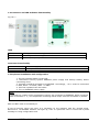
1.4 Connector and LED Indicator Functionality
Fig. No. 1
LEDs
STAY
ARMED
BYPASS
STAY (perimeter security) state indicator
ARMED (armed security) status indicator
BYPASS (temporary zone disconnection) status indicator
Connector Functionality
+12V
DATA
GND
Positive supply pin +12-14 VDC connected to the main unit AUX
Data pin connected to the main unit DATA
Negative supply pin connected to the main unit GND (COM)
1.5 Keyboard installation and configuration
1. Fix the keyboard holder to the wall.
2. Disconnect security system ESIM262 power supply and backup battery before
connecting wires.
3. Connect keyboard connectors to ESIM262. Accordingly, +12 V must be connected
to AUX, DATA – to DATA, GND – to GND.
4. Infix the keyboard into the holder.
5. Turn on ESIM262 power supply.
Note
If DALLAS key reader and/or temperature sensor are connected to ESIM262, DATA connector
used is the same. I. e., all components containing DATA output must be connected in parallel.
ESC and ENT must be constantly lit.
If not all security zones are used, it is necessary to use resistors with the unused zones.
Otherwise a red BYPASS indicator will light up, even if a particular zone is turned off by SMS
message or using configuration tool.
User manual EKB1 v1.0
5
BYPASS – temporary zone disconnection
To turn on BYPASS mode for any zone, press the buttons in the following sequence:
ESC Zone_NO ENT
E. g., to disconnect zone 5 press ESC 5 ENT.
Red LED indicator will light up immediately. To turn off BYPASS mode enter analogous command
sequence ESC 5 ENT. The indicator will switch off.
Turning on BYPASS mode using the keyboard is analogous to the command sent by SMS
message: XXXX_Z(1-6):OFF.
User manual EKB1 v1.0
6
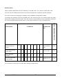
Service mode
Factory default parameters are the following: user PIN code 1111. Service mode code 1470.
The user will be notified about the service mode actuation by a blinking red LED indicator.
It is most convenient changing all settings using “ESIM262 Configuration TOOL”.
Description
Command
1
4
7
0
ENT
1470 default
PIN
5.25
Entering premises
delay time.
0
1
X
X
ENT
XX=[0-99]s
5.25
User PIN code
change.
0
2
X
X
X
X
ENT
Service mode PIN
code change.
0
3
X
X
X
X
ENT
Entering service
mode.
ESC
Possible values
Starting with ESIM262 version
To change the settings using the keyboard the user must first turn on service mode and after
making the changes exit the mode. The user will be informed about every successful command
by a sound signal beeping several times. In the case of failure or error it will beep once.
It is necessary exiting service mode after making configuration!
User manual EKB1 v1.0
7
XXXX={0…9}
5.26
XXXX={0…9}
5.26
Made in Lithuania.
www.eldes.lt
User manual EKB1 v1.0
8