1
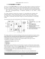
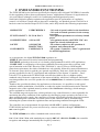
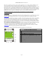
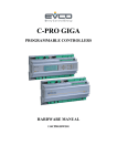
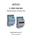
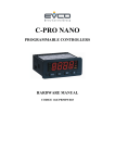
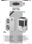
EVDFAN3000
3 – PHASE VOLTAGE REGULATOR
WITH PHASE – CUT MODULATION
FOR AXIAL FANS
ASINCRONOUS MOTORS
HARDWARE MANUAL
CODICE 114EVDF30E00
EVDFAN3000 HARDWARE MANUAL
Pag. 2
EVDFAN3000 HARDWARE MANUAL
Important Notice
This Instruction Manual should be read carefully before installation and before use, and all warnings relating to
installation and electrical connections should be observed; the Manual should then be kept for future reference.
The device must be disposed of in accordance with local regulations governing the disposal of electrical and
electronic devices.
Pag. 3
EVDFAN3000 HARDWARE MANUAL
Table of contents
1
2
INTRODUCTION ....................................................................................................................... 7
EVDFAN3000 FUNCTIONING ................................................................................................. 8
2.1
2.2
2.3
3
ELECTRICAL CONNECTIONS .............................................................................................. 14
3.1
3.2
3.3
3.4
4
Magneto thermal protection........................................................................... 15
Connection of power supply and load ........................................................... 15
DIP-Switch (DSw1 … DSw8)....................................................................... 17
Control signals & Auxiliary contacts connection.......................................... 17
REMOTE CONTROL SIGNALS 0-10 Vdc /
4.1
4.2
5
EVDFAN3000 voltage regulator description ................................................ 10
EVDFAN3000: Technical Features .............................................................. 11
Installation and Mechanical Dimensions....................................................... 13
4-20 mA / PWM .......................................... 18
AUXILIARY CONTACTS & SIGNALS terminal block (M3) ................... 19
RL1 Alarm relay terminal block (M4) .......................................................... 19
ALARMS ................................................................................................................................... 20
Alarm Led DL3 ....................................................................................................... 20
Pag. 4
EVDFAN3000 HARDWARE MANUAL
Safety warnings
Follow the instructions in this manual exactly and observe all safety measures in force. Always keep the present documentation close to the control
device.
The purchaser must previously ascertain the suitability of the product for the use it is intended for and assume all consequent risks and responsibility.
This product has been designed to be used only as an operational control device. In the event delicate or great value products should be held within
specific working limits, it is recommended to install a separated control device, equipped with alarm contacts.
The commissioning, start-up and operation of the present device must be performed by qualified technicians with knowledge of the technical
regulations in force, in compliance with all the safety standards and able to understand the indications of danger.
The regulator must be installed by qualified personnel who will connect the electric supply, attach the cables in their permanent positions and
commission the plant. Incorrect installation of the DRV300 voltage regulator or the fan connected to it may cause damage to objects or people.
Before supplying power to the unit, make sure that the regulator is correctly connected to the power supply and to earth.
The information provided in the present manual consent to install and control correctly the fan speed regulator EVDFAN3000.
Do NOT tamper with or disassemble the regulator internal components; doing so will INVALIDATE THE GUARANTEE and may cause
unnecessary damage.
The regulator does not contain components that can be repaired by the user.
The regulator must be suitably and effectively earthed by the installer according to the standards in force; Earth is essential for the EMC filter to
operate correctly.
The user must be protected from the electric supply and the motor must be protected from possible overloads in compliance with the standards in
force.
DO NOT supply the regulator without the external protection cover.
DO NOT touch any electrical parts of the circuit when the power supply is connected under any circumstances.
Before supplying power to the unit, make sure that the regulator is correctly connected to the power supply and to earth;
If the mains supply is "disturbed", which may be due to other electrical power components causing irregularities in the supply (power contactors), it is
recommended that supplementary three phase ‘SURGE ARRESTER’ filters are installed directly on the regulator supply.
Avoid repeatedly connecting and disconnecting the power supply to the regulator; a constant supply keeps the regulator at working temperature and
eliminates problems caused by condensate inside the protection case.
Alternatively, use the remote terminal board contact ‘M3’ S2 = ON/OFF.
The S2 = ON/OFF contact on the terminal card M3 does not cut the mains supply and therefore cannot be used as a safety switch.
Install the regulator out of direct sunlight, in order to protect the case from overheating.
The appliance can operate at environmental temperatures up to 50°C. Do not install it where this temperature may exceed, otherwise the integrity of
the regulator will be compromised, since the controller may make the user appliance operate at full load (100%) with all consequent effects.
The equipment must be placed vertically, in order to encourage heat dissipation and to ensure sufficient air circulation in a free space measuring at
least 150 mm above and below the regulator. If several regulators are to be grouped together on a single electric board, please provide forced air
circulation with a fan or with a sufficiently powerful cooling unit.
Use the holes on the lower and power terminal board sides of the appliance, for entrance of the connection cables. This will prevent water, dust etc.
from getting in and will ensure the IP55 protection level is maintained using adequately sized cables and sheaths of suitable quality.
Reassemble and check the cover of the external protection panel is properly closed.
DO NOT alter or damage the identification stickers on the equipment.
Terms of use
The EVDFAN3000 series devices are designed to vary the three-phase AC voltage thanks to the phase cutting principle, in order to
regulate the rotational speed of three-phase asynchronous high-slip motors, to be used with axial and centrifugal fans in AirConditioning, Refrigeration, Ventilation and Air Treatment Systems. Any different use of the equipment is strictly
FORBIDDEN.
Manufacturer Declaration
REGOLAZIONE ELETTRONICA DEI VENTILATORI NEL PIENO RISPETTO DELL’AMBIENTE
This series is manufactured for the employment into the industrial environments and responds the following communitarian
directives:
• Machine Directive 2006/42/EC and following amendments
• Low Voltage Directive (LVD) 2006/95/EC
• EMC Directive 2004/108/EC
(*) ELECTRONIC FANS REGULATION - FULL ENVIRONMENTAL RESPECT
Thanks to the electronic solutions used, the device responds totally to the emission limits required from the European Directives for
Residential, Commercial and Light Industrial environments (EMC and PDS applications), and can therefore be installed without
particular precautions ( ex.: shielded cables).
The equipment does NOT contain filters for the suppression of harmonic distortions.
Pag. 5
EVDFAN3000 HARDWARE MANUAL
EC Directives & Technical Standards
Like all of our products, the EVDFAN3000 series has obtained the CE mark in compliance with the EMC (Electromagnetic Compatibility) directive
2004/108/EC.
The essential requirements of the directive are satisfied by the conformity to the “generic standards” for industrial environments.
Directive
Standard code
Description
2006/42/EC
EN 60204-1
EN 60204-1
EN 50178
Safety of machinery. Electrical equipment of machines.
Safety of machinery. Electrical equipment of machines.
Electronic equipment for use in power installations.
Adjustable speed electrical power drive systems. Part 3: EMC
product standard including specific test methods.
2006/95/EC
2004/108/EC
EN 61800-3
All products have been tested in accordance with the procedures and test conditions laid down in the standards specified in the
product technical file.
Since these products are destined to be used not only as “stand alone” systems, but also as components of other machines or plants,
all compatibility tests to the standards have been performed under typical conditions of use.
In particular, the tests have been performed in a system consisting of a voltage controller EVDFAN3000, a control cable and relative
commands, a supply cable, a motor cable and a group of fans with an equivalent power to the value of the nominal current of the
controller.
With reference to EMC Compatibility, according to the Marking
EMC
LVD
with
CDM System
with
oonnllyy R
Reegguullaattoorr
PDS System
R
Reegguullaattoorr ++ FFaann
All EVCO controllers are suitable for the installation in PDS systems (Power Drive System = Controller with
connected fan/s), which guarantee the EMC compliance of the System “Controller + Fan/s”.
The final specifications of the system or plant, in compliance with the EMC directive, are in any case the
responsibility of the installer, who must put the system into operation carefully, according to the rules in force
and following the information provided by the present manual.
PRODUCT end of life EU 2002/96/EC
The device must be disposed separately, according to the local authority
advice.
Pag. 6
EVDFAN3000 HARDWARE MANUAL
1 INTRODUCTION
The devices of the EVDFAN3000 series are phase-cut voltage regulators, completely controlled on
the 3 phases, for RMS voltage connected to the load modulation without neutral cable connection.
The device is suited for working as power stage SLAVE with function selection by DIP-Switched:
• Power stage SLAVE: the output AC voltage varies depending on the command signal (PWM,
VDC, mA) increasing/decreasing its amplitude depending on the DSW 2 setting
(Direct/Reverse).
The voltage regulators are designed for varying the AC voltage RMS value depending on the
command signal for 3-phase asynchronous motors coupled with axial fans, pumps, mixers
The voltage control is carried out partializing the sinus wave voltage input, it does not generate
torque pulses, is particularly silent and the voltage loss is limited to maximum 1% of the supply
voltage.
The picture below shows the block diagram of the EVDFAN3000 voltage regulator
A – Power circuit
B – Network filter and EMC
protections
C – Power supply and
syncronism signals
D – Insulators for power board
command signals
E – Control and regulation circuit
F – Power board controller
The voltage regulators are sized for standing an in rush current about double the rated one, during
selection of device is critical to take into consideration the motor inrush current besides its type.
In fact, while for the axial fans motors the inrush current is 2-3 times the rated ones, for the
centrifugal fans motors the inrush current could be up to 7-8 times the rated one.
Concerning the motor type is critical to select a model suitable for this type of control.
As guideline is preferable to use motors with:
• Silumin high slipping resistive rotor
• Defluxed
• Tropicalized
• CLASS H
since they give better performances in speed variation, are quieter and need lower inrush currents.
When choosing the motor, it is always recommended to contact your equipment supplier and order
a motor suitable for voltage variation (ADJUSTABLE) and perform practical tests of the motors or
prototype machines, in order to verify their proper operation.
Once chosen the motor the voltage regulator should be selected according to:
• The rated voltage
• The maximum current load (load Ampere) taking into account the inrush current.
Before installing the EVDFAN3000 regulator, you are invited to read this manual which describes the
necessary procedures for correct installation and commissioning of the controller EVDFAN3000
Pag. 7
EVDFAN3000 HARDWARE MANUAL
2 EVDFAN3000 FUNCTIONING
The EVDFAN3000 series has been specifically developed to offer a digital UNIVERSAL controller
for the regulation of three-phase asynchronous motors, with dedicated software for applications on
Air-cooled Heat Exchangers used in Air Conditioning and Refrigeration Systems.
Such kind of digital regulation optimizes the application-specific performance of ventilation
control; it is based on a simple and yet innovative technology, one hundred percent ITALIAN as it
has been conceived and developed in EVCO labs, and it fully satisfies the following requirements:
SIMPLICITY
USER FRIENDLY
FUNCTIONALITY PLUG & PLAY
COMPLETENESS
ALL in ONE
SAFETY
ALL ROUND
PROTECTION
COMPLIANCE
CONFORMITY
- NO need of special cables for the installation
- NO need of trained operators for the startup
procedure
- all regulation parameters are already default
preset
- all regulation modes with PWM–VDC–mA
signals are already default preset,
- the software supervises the operation of
regulator and connected fans,
- the system “Controller + Fan/s” is guaranteed
for all PDS applications
As a consequence, the digital EVDFAN3000 regulators are:
-SIMPLE, what concerns electrical connections and programming,
-FLEXIBLE and ready to be used, as it is already preprogrammed for all SLAVE applications,
-COMPLIANT, in conformity to the strictest standards concerning power drive systems, with
special attention to the EMC Directive (EMC-EN61800-3): since it refers to NON tangible
protection requirements, the relative Standards are only partially followed by many manufacturers
of electronic power devices, and they are ignored especially by final users, which are the contact
persons responsible for the CE certification and compliance of the System “Controller + Fan/s”.
Like all EVCO products the EVDFAN3000 series has been built to the very highest quality
standards using electronic components of the utmost reliability, which have undergone functional
tests that guarantee the use of the product for at least 60,000 hours of continuous operation without
problem.
Thanks to the specialized software for applications on fan motors, it is possible to avoid typical
problems with the modulation of oscillation, to reduce the mains current distortion and to limit the
magnetic noise of the regulated motor by means of the Soft-Power technology, which manages
power regulated in 0-cross mode.
The extended range microprocessor, which performs every control function, is also responsible for
monitoring the safety conditions of the regulator by checking its proper operation, the lack of one
phase toward the power supply, the connection of sensors and all other possible electrical situations
that could damage the connected air-cooled system or the controller, and by simultaneously
informing the operator about the regulation status and operating conditions through the LEDs.
The controllers are preprogrammed for operation with SLAVE (3 modes) configurations:
EVDFAN3000 operates as a power unit, driven by a remote controller, through a PWM, VDC or
mA control signals.
The EVDFAN3000 series offers 4 standard rated current values:
8 A / 12 A / 18 A / 28 A, with standard power supply 400VAC +20/-10% 50/60Hz (the controller
recognizes and manages automatically the frequency variation).
Pag. 8
EVDFAN3000 HARDWARE MANUAL
Electronic regulations of motors, phase cutting regulation of AC voltage, SCR and TRIAC power
drive systems: they all have collateral effects, which require the use of additional technical
protection measures especially with applications in residential environments or technological plants;
the acoustic noise - generated by the fan because of the magnetization of the motor itself – arises
discontinuously within the main speed ranges of the fan speed regulation, and can be only partially
reduced by means of expensive and bulky acoustic screens installed around the machinery.
The regulator does NOT have any internal filter for the suppression of harmonic distortions
(EN-61000-3-2 & 3-12)
CAUTION
The EVCO product is technologically advanced and its working modes are specified in the tecnical
literature supplied along with the device or can be downloaded from the company web page
www.evco.it.
The customer (manufacturer, designer or installer of the final equipment) takes all the responsibility
and risks related to the configuration of the device concerning the achievement of the expected
results for the specific final equipment/plant. The lack of an appropriate evaluation stage, which is
required/pointed out in the user manual, can prevent the correct working of the final product which
EVCO cannot be considered responsible for.
The customer have to use the device only in the modes described in the technical literature relevant
for the device itself. The EVCO responsibility related to its product is ruled by the EVCO
”GENERAL CONDITIONS OF SALE” which can be downloaded from the company web page
www.evco.it and/or by specific agreements with the customer
In the picture is shown EVDFAN3000 with the description of its various parts
EVDFAN3000 LEGEND
1
2
3
4
5
6
7
8
9
10
11
12
Gland for connecting cable way out
3-phase load connection (U-V-W) + Ground
Power supply PE connection and Motor/s GND
3-Phase (R-S-T) power supply connection
TPN closing screw (CEI 23-58) Max. torque 2,5Nm
Bracket with holes for regulator wall mounting
GW plast 120°C housing
Command analogue inputs switchboard
Reset pushbutton
Alarm relays switchboard
Status LEDs
Programming DIP-Switches
Pag. 9
EVDFAN3000 HARDWARE MANUAL
2.1 EVDFAN3000 voltage regulator description
The 3-phase voltage regulators of the EVDFAN3000 series are realized in a single PCB board on a
fiberglass support mounted inside a IP55 GW plast 120°C housing. The PCB board has the
control circuit in the upper zone and the power circuit in the bottom zone.
The below regulation, connecting and signalling parts are present in the control circuit:
LED
DL1
DL2
DL3
DL4
DL5
PWR
CPU RUN
FAIL - KO
PWR OUT
% PWM
green
Power supply connected and OK
green
Microprocessor working correctly (blinking)
red
Phase sequence/loss or undervoltage alarm
green
Regulated voltage to load
green
% of PWM input signal
green
Status of ALARM relay – RL1
DL6=OF
F
DL6=O
N
1-3=ON
12=OFF
48 Vac
5 Amp 1-3=OFF
1-2=ON
DSw / Dip-Switch
12345678
DSw Dip-Switch All OFF : standard configuration
DSw1- DSw8 ON position: regulation options functions enabling
Morsettiera M3 Command and auxiliary signals connection
Morsettiera M4 Connection to (changeover) alarm relay RL1
The below switchboard for connection of the power cables is placed in the power circuit
Power SWITCHBOARD
- 3-Phase power supply voltage
L1-L2-L3 (RST)+PE
- 3-Phase load U, V, W + GND
Pag. 10
EVDFAN3000 HARDWARE MANUAL
2.2 EVDFAN3000: Technical Features
Voltage
Voltage limits
Power supply
Frequency
Overvoltage Protection
Mains monitoring
400VAC Three-phase - ( on request 230VAC / 500 VAC)
Lower: 380 VAC – 10% (below this limit DL4 is ON)
Upper: 440 VAC + 10% (over 500 VAC SURGE FILTERS should be ON)
50 / 60 Hz automatic selection
For Installation Category II ( 4 KV )
Monitoring of the presence of all 3 phases. The lack of one phase causes the device stop with
DL4 active and activation of alarm and relevant relay
Operating
principle
Electronic three-phase voltage regulators for the phase-cutting regulation (through SCR, total control on the
three phases) of the active voltage applied to the load; compensation for inductive loads and motors. The phase
sequence is automatic and the load can be connected either star or delta.
Current
Rated RMS current
@ 50°C
ambient temperature
Power
Operating
characteristics
Overload
Control circuits
Thermally dissipated
4W/A
SLAVE
CONTROLLERS
rS
Analog control
signals
INPUT Signals
& Contacts
Logic control signal
OUTPUT
Signals &
Contacts
The output voltage varies according to the value of the remote control signal
DIRECT: the output increases as the input increases,
REVERSE: the output decreases as the input increases.
Default: the VAC output increases as the controlled variable increases
The controller can be preset through DIP switches for working with any
combination of the following operating modes:
0 – 10 Vdc (*)
Ri = 10 kOhm
4 – 20 mA
Ri = 100 Ohm
PWM digital signal, from 3V to 30V, insulated and not polarized.
PWM
3 to 30 V
Start-Stop
Programmable voltage free “ON/OFF” contact: with Sw4 (for NO or NC)
T.K. motor
Voltage Free “ON/OFF” contact (NC)
Analog control signal
Slave Unit control signal : 0-10 VDC - max 30mA
Auxiliary Supply
+20V +/- 20% , max 40mA not stabilized, protected from short-circuit
RL1 Relay
Dip Swicht
Available
functions
selections
8 A up to 50°C ambient; if over, decrease 0,6 A/°C
EVDFAN3080
12 A up to 50°C ambient; if over, decrease 0,6 A/°C
EVDFAN3120
18 A up to 50°C ambient; if over, decrease 0,6 A/°C
EVDFAN3180
28 A up to 50°C ambient; if over, decrease 1,0 A/°C
EVDFAN3280
150% of the rated current (max. 10” every 3’)
5VA
EVDFAN3080
32 W @ 8A
EVDFAN3180
72 W @ 18A
EVDFAN3120
48 W @ 12A
EVDFAN3280
112 W @ 18A
DSw
12345678
Contact COM , NC, NA for Alarm relay RL1
DSw
DSw
DSw
DSw
DSw
DSw
DSw
DSw
1
2
3
4
5
6
7
8
Select the regulation 0-10VDC or 4-20mA
Select the regulation mode: Direct / Reverse
Select the regulation: Linear / Quadratic
Select the NO/NC function mode of the Start-Stop
Select the RL1 alarm mode (bit 1)
Select the RL1 alarm mode (bit 2)
Enable the CosPhi adjust
Available for CUSTOMER custom, on request
Pag. 11
EVDFAN3000 HARDWARE MANUAL
Visualisation
Leds
Predispositions
PWR
DL1
Green
CPU RUN
DL2
Green
Alarm FAIL
DL3
Red
PWR OUT
%PWM IN
RL1
DL4
DL5
DL6
Green
Green
Green
Starter
Cut-Off
Input command
Alarms
Power supply
Mains phases monitoring
Protections
Case
Insulation
Environmental
conditions
Installation
Power supply ON
Regulation O.K. : blinking DC 50%, frequency 0,5 Hz
Regulation CosPhi ON : blinking DC 50%, frequency 2 Hz
1 blink
Board overtemperature (>85°C)
2 blinks
3 blinks
VAC power supply phase loss
Thermal protection open
Over range signal :
4 blinks
4-20mA : < 2mA ; > 24mA
0-10VDC : > 11,0 VDC
Running: VAC output on work
PWM % on input (M3: 8/9)
RL1 relay (active if relay is energized)
Fixed, 5”
The regulation is set at the 25% of the VAC power supply
Verify the input signal range :
- 0-10 VDC > max value under 11Vdc
- 4-20 mADC > min value 2mA and max value 24mA
Phase loss – Power supply under range (less 20% VAC supply)
Verify the phase sequence and phase-loss and stops the regulation if the AC voltage
is 20% below the rated one or in case of phase loss/incorrect phase sequence. Alarm
ON with Led DL4 (red) & relay RL1 (OFF)
Verify the working °C with internal probe (max 85°C)
Working controller
Overvoltage protection
Complying with EN 61000-4-5: Overvoltage Category II (4 KV)
Auxiliary supply voltage
With PTC for preventing failures due to short-circuits
Internal temperature
Internal thermal protection
Available cases
IP55
Materials
GW-Plast 120°C (max. temperature 120°C) and aluminum
Locking screws
TPN series with max. tightness 2,5 Nm. (according to CEI 23-58)
Protection degree
IP 55 using Gland KIT
Environmental pollution
High pollution
Fire resistance
D Category
Case
Class I (use of protective earthing conductor)
Control circuits
4000VAC between control input and mains voltage components
Working temperature
-20 T 50 (–20°C to + 50°C) for temp < -10°C , use Start Stop contact
Storage temperature
-30 T 85 (–30°C to + 85°C)
Humidity
RH < 85% non condensing
Vibrations
Lower than 1G (9.8 m/s2)
Wall mounting ONLY in vertical position, with N° 4 holes ∅ 6 mm.
Flexible cable, rated cross section 1,5 mmq / 15 AWG
Signal connections
Electrical
Connections
Power connections
Compliance
2006/42CE
EVDFAN3080
EVDFAN3120
EVDFAN3180
EVDFAN3280
2006/95CE
Pag. 12
Flexible cable, rated cross section min. 2,5 mmq / 13 AWG
Flexible cable, rated cross section min. 2,5 mmq / 13 AWG
Flexible cable, rated cross section min. 6.0 mmq / 9 AWG
Flexible cable, rated cross section min. 10.0 mmq / 7 AWG
2004/108CE
EVDFAN3000 HARDWARE MANUAL
2.3 Installation and Mechanical Dimensions
The EVDFAN3000 regulator have to be always stably mounted and fixed throughout the four (4)
fixing holes suited on the lateral brackets, before its electrical connection.
The EVDFAN3000 is always available in the IP55 version for indoor or outdoor installation. The
IP20 and IP00 versions for installation inside an electrical cabinet are available upon request only
for some models (see mechanical dimension table below). The device is cooled for natural
convention therefore there must be enough clearance above and below. Therefore ensure to have at
least 150 mm clearance above and below the device
These versions have a high resistance (IK degree = 08) GW-plast 120°C case. The holes on the
bottom part are intended for the electrical power cables entrance:
• Regulator power supply 4 poles line (3-phases + PE)
• Load power supply 4 poles line (3-phases + PE)
• Signal cables for analogue and digital inputs/outputs
In order to simplify the installation all the regulators are equipped with a standard set of polyamide
glands (PA6 – class V2 – IP68) suitable for power and signal cables passage.
Model
Rated Current RMS
Ampere
kVA
EVDFAN3080
8
5,5
EVDFAN3120
12
8,0
EVDFAN3180
18
28
12,0
EVDFAN3280
DIMENSIONS (mm)
IP
55
55
55
55
A
253
285
285
350
18,6
IP55
Pag. 13
B
234
201
201
235
C
116
130
162
204
E
210
153
173
173
F
200
255
255
320
WEIGHT
2,5
3,8
4,5
7,5
Ø FIXING
6,0 mm.
6,0 mm.
6,0 mm.
6,0 mm.
EVDFAN3000 HARDWARE MANUAL
3 ELECTRICAL CONNECTIONS
The regulator EVDFAN3000 allows the connection of three-phase asynchronous motors, in
applications whose motor torque-speed characteristic IS quadratic. Thus it is especially suitable
with axial fans, while centrifugal fans can be connected only if purposely specialized for the phasecutting regulation.
The correct electrical connection and the supply voltage are reported on the motor data plate; the
direction of rotation of the motor can be changed by swapping two of the three supply cables.
It is important to keep the power supply cable as short as possible, so as to minimize interferences
and leakage (10 / 15 mt); otherwise it is recommended to install an auxiliary three-phase filter on
the controller’s output.
DELTA for High speed connection
The windings voltage is:
The windings current is:
STAR for Low speed connection
The windings voltage is:
The windings current is:
For the connection use rubber (FG7) or PVC cables taking into consideration the rubber insulation,
which allows a limited cable cooling, stands higher temperature. In fact the PVC cables temperature
cannot exceed 70°C whereas the rubber insulated cables can stand up to 90°C temperature. For this
reason the cables working temperature should be referred to the insulation material. There could be
some problem close to the connecting terminals where the temperature variation could cause the
loosening of the fixing screws and the terminal overheating due to electrical resistance increasing.
For this reason is critical that the insulation is NOT inserted into the terminal reducing the contact
surface.
Cable size
1,5 mmq
2,5 mmq
4,0 mmq
10,0 mmq
Max. Ampere (In
*)
6 A / 10 A
10 A / 16 A
16 A
32 A
(*) If the total ampere are equal to the nominal current, use the
upper size cable; For the right connection, see the figure
OK
NO
NO
The EVDFAN3000 regulator can control several motors connected in parallel, assuming that the
absorption of their total current does not exceed the rated current indicated on the EVDFAN3000
data plate.
The speeds of the motors vary at the same time; variances in behaviour during start up and at low
speeds are due to slight differences between the motors, even if they are of the same type;
However, if the required motor speeds have to be different, motors with different rated speeds must
be used. Bear in mind that motors with very different characteristics create heterogeneous electrical
situations, which may show problems on start up and at low speeds because of different resistances
of the stators which require different voltages on start up and at low speeds.
Pag. 14
EVDFAN3000 HARDWARE MANUAL
3.1 Magneto thermal protection
The EVDFAN3000 devices must be protected by a magneto thermal switch for preventing shortcircuits and/or overload fitted upstream of the regulators; Installation of magneto thermal
protections is the responsibility of the installer and consist of:
• 3 ultra speed fuses, suitable for semi conductors protection, able to protect against short circuit
load side the power components (SCR) used for the regulation
• 3 phase magneto thermal switch with ‘C’ intervention curve
The installation of those protection devices ensures the electrical integrity of the regulator. Below
the model/ratings of the recommended protections:
Model
Specialized Protection FUSE for SCR (*)
Magneto thermal Switch
(max rating recommended) Size
Vac
Amp
Reference
EVDFAN3080
EVDFAN3120
EVDFAN3180
EVDFAN3280
16 A
20 A
32 A
40 A
10 x 38
690 V
14 x 51
12
16
25
32
FR10GB69V16
FR10GB69V16
FR10GB69V25
FR14GC69V32
(*) to protect SCR-Power-Semiconductor of the EVDFAN3000 regulator, use Ferraz-Shawmut (or
similar) specialized fuse for electronic power applications.
3.2 Connection of power supply and load
Connect the power supply and the load as shown in the figure below, being careful to employ
conductors with a cross section suitable to the connected load.
The power cables (power supply and load), must be installed separately from the control cables
(analog inputs and ON-OFF input/outputs), keeping the maximum possible distance between the
power and signal conductors.
Do not place power cables with signal cables in the same raceway. In case the cables cross one
another, ensure it is at 90°.
SURGE ARRESTER: electric protection placed between the regulator supply and the earth,
meant to protect the device from transient overvoltage.
WARNING: disconnect the faston contact from the PE earth reference, before making the
“ELECTRIC STRENGTH TEST”.
WARNING: In presence of a protection with DIFFERENTIAL SYSTEM, use switches with
leakage current to earth ≥ 100 mA )
The EVDFAN3000 regulators allow the connection of three-phase loads without requiring the
connection of the
neutral.
This simplifies installation and facilitates the STAR or DELTA load configuration.
It is advisable to provide a Bypass Switch to allow the load activation, even when the cutting
regulator is faulty
(emergency by-pass).
When connecting the Bypass, the following precautions should be taken into consideration:
The connection through the Bypass Switch must keep the phase correspondence
unaltered so as to avoid destructive short-circuits and maintain the sense of rotation of
the motor.
Before supplying the load with maximum voltage, the supply should be disconnected from
the Regulator. Therefore:
It is advisable to use a three-position manual switch as a commutation device
Pag. 15
EVDFAN3000 HARDWARE MANUAL
If automatic commutation is performed by means of contactors, make sure there is some
delay (at least 2 seconds) between regulator disconnection and load activation
SURGE ARRESTER
complying EN 61000-4-5
U V W PE R S T
PE faston
Scollegare per il test di rigidità elettrica
Disconnect before electric strenght tes t
Débrancher po ur le test de rigi dité électrique
Für elektrische Festigkeit trennen
L 1 L2 L 3
Magn etotermico : tip o C
Magn etoth erm al : type C
Magn éto-t hermique : modèle C
Magn etoth erm ischen : m odell C
BY-PASS
PE ALIMENTAZIONE
L1 POWER SUPPLY
ALIMENTATION
L2
EINSPEISUNG
L3
VENTILATORI
FANS
VENTILATEURES
VENTILATOREN
Pag. 16
EVDFAN3000 HARDWARE MANUAL
3.3 DIP-Switch (DSw1 … DSw8)
On the upper side of the regulator card there is an 8 positions DIP-Switch array (DSw1 a DSw8)
which allows the easy modification of the EVDFAN3000 settings at any time.
The below table describes the standard functions available and their possible modifications.
Dip Swicht (DSw)
ON
OFF
ON
OFF
ON
OFF
ON
OFF
1
2
3
4
Description
Selection for 4-20 mA control signal on inputs
Selection for 0-10VDC control signal on inputs
Reverse mode : the VAC output increases as the input command increases
Direct mode : the VAC output decreases as the input command increases
Quadratic function mode
Linear function mode
Start/Stop :for NC external contact (ON = run ; OFF = Stop)
Start/Stop: for NO external contact (OFF = run ; ON = Stop)
Available Alarm relay setting functions: see the table and watch on the display
DSw selection
DSw 5
5&6
With ALL O.K. >>> RL1 = ON >>> led DL6 = ON
OFF
DSw 6
OFF
ON
OFF
RL1 = OFF
OFF
ON
RL1 = OFF
ON
ON
RL1 = OFF
RL1 = OFF
With ONE or more activated Allarms
With ONE or more activated Allarms
With remote contact STOP = ON (S2 Stop/Start)
With ONE or more activated Allarms
With remote contact STOP = ON (S2 Stop/Start)
With VAC output = 0% (Fans OFF)
With Power Supply OFF
.
7
8
ON
OFF
ON
OFF
Activation of the Cos-Phi setting modification (only factory procedure)
Normal function (factory Cos-Phi)
Available custom function on request
OFF
N.B. After the Dip-Swicht (DSw) selection, press RESET : SB1; the
controller restart with the new selected function
With DSw 5&6 = ON/ON, the alarm relay change to COM-NC
position only with the OFF of the Power Supply
(1)
(2)
12345678
12345678
DSw
3.4 Control signals & Auxiliary contacts connection
The figure below shows the label placed inside the regulator, which reproduces the electrical
connections of control sensors/signals and of the available auxiliary contacts.
11
10
9
8
7
6
5
4
3
2
1
PWM
PWM
T.K.
GND
Start/Stop
OUT 0-10V
NOT USED
NOT USED
GND
IN
NOT USED
PWM digital signal, from 3 to 30V (10 mA max), insulated and not polarized
Connection of the thermal contact (NC)
Ground Referenced
NO/NC contact (Sw4 selection) for regulation Stop/Start
0-10VDC (max 20mA) output, for SLAVE extra power unit
Ground Referenced
Input for 4-20 mA 0-10VDC
Pag. 17
(3)
EVDFAN3000 HARDWARE MANUAL
4 REMOTE CONTROL SIGNALS 0-10 Vdc /
4-20 mA / PWM
Below are represented the connections for the remote control regulations : 0-10Vdc, 4-20 mA e
PWM, coming from remote control unit, for Automatic regulation or Manual regulation (with
Potentiometer);
with DSw2=ON, the controller work on Reverse mode: 10-0Vdc or 20-4mA (for rS selection)
For REVERSE mode (input: 10-0V or 20-4mA): shift DSw/2 to ON position
Input
010VDC
4-20mA
DIRECT mode
IN
min
0,9
VDC
4,5
mA
Output
MIN
VAC
IN max
140 VAC
9,5 VDC
130 VAC
19,0 mA
REVERSE mode
% VAC_in
% VAC_in
100%
100%
IN
0%
0VDC
4mA
IN
0%
0VDC
4mA
10VDC
20mA
Pag. 18
10VDC
20mA
Output
MAX
VAC
100%
VAC
100%
VAC
EVDFAN3000 HARDWARE MANUAL
4.1 AUXILIARY CONTACTS & SIGNALS terminal block
(M3)
On the M3 signals connections, there are available:
START/STOP (S2) : contact NO/NC (Dsw4 selection);
T.K. : contact NC, for thermal protection
0-10Vdc output, for extra power (SLAVE units)
Auxiliary
Contact
OUT
8–6
S2
8–7
TK
8–9
0-10VDC output signal
for other SLAVE units
DSw4=OFF
Remote
contact
DSw4=ON
Thermal contact
NC
Auxiliary
OUTPUT
OUTPUT (0-10V max 20mA): this output is available for the
regulation of other SLAVE units and follows the regulated AC
voltage output (U-V-W) depending on the DSw2 settings. The
DC voltage signal is proportional to the input command
SIGNAL
&
ON-OFF
contacts
NC
NO
DSw2 = ON
0-10 VDC out
DSw2 = OFF
10-0 VDC out
S2=OFF
S2=ON
Working Enabled
Working Enabled
S2=ON
S2=OFF
TK=ON
Working Enabled
TK=OFF
Stop
Stop
Thermal
Alarm
4.2 RL1 Alarm relay terminal block (M4)
On the upper side of the controller card, there is the RL1 Alarm relay, with programmable function
for different level of warning.
With the factory selection, RL1 switch from NC position (1&2) to NO position (1&3).
Different alarm levels are selectable with the DSw 4&5 selection.
N.B. Aftyer the DSw selection, to confirm the change, press the RESET : SB1 button.
With DSw 5&6 on position ON/ON, the alarm relay switch from NC position only with the
Power Supply OFF.
Available Alarm relay setting functions: depending on device status as shown in the below table
DSw selection
DSw 5
DSw 6
OFF
OFF
RL1 = OFF
ON
OFF
RL1 = OFF
OFF
ON
RL1 = OFF
ON
ON
RL1 = OFF
Pag. 19
with RL1 = ON >>>
led DL6 = ON
In case of 1 or more active alarms
In case of 1 or more active alarms
With device in STOP mode (from S2 contact)
In case of 1 or more active alarms
With device in STOP mode (from S2 contact)
With VAC output = 0% (fans OFF)
With Power supply voltage OFF
EVDFAN3000 HARDWARE MANUAL
ALARM selection table for relay RL1 function
ALL-1 (COM-NC) ALL-2 (COM-NC)
ALL-3 (COM-NC)
DSw 5 & 6
Power Supply OFF
Power S. under range
Controller K.O.
Phase loss
ALARM mode
Selection for
RL1 function
Power Supply OFF
Power S. under range
Controller K.O.
Phase loss
Remote STOP active
12345678
12345678
Power Supply OFF
Power S. under range
Controller K.O.
Phase loss
Remote STOP active
VAC output = 0%
12345678
ALL-4 (COM-NC)
RL1= COM-NC
only with
Power Supply=OFF
12345678
5 ALARMS
Alarm Led DL3
The alarms are displayed also by DL3 Alarm LED “FAIL”
The number of blinks indicates the type of alarm.
DL3
1 blink
2 blinks
3 blinks
4 blinks
FAIL - KO
Overtemperature Control card (>85°C)
Phase loss on power supply
T.K. contact OPEN
Input signal (IN) over range (*)
In case more alarms are present at the same time, the one with higher priority is indicated
(corresponding to a lower number of blinking). In normal condition (no active alarms) the LED
DL3 “Fail” remains OFF
(*) Input signal Minimum and Maximum limit for the possible configurations
Command signal
4 – 20 mA
0 – 10 VDC
Minimum value
2,0 mA
---
DL6
RL1
D L6
Maximum value
24 mA
11 VDC
green
48 Vac
5 Amp
Indicates the state of the ALARM relay
DL6=ON
DL6=OFF
1-3=OFF
2-3=ON
1-3=ON
2-3=OFF
The alarms are not memorized; Once the alarm cause runs out the corresponding signal is
disabled and the units starts again the normal working mode
Pag. 20
EVDFAN3000 HARDWARE MANUAL
Hardware Manual for EVDFAN3000.
Version 1.00 - December 2010.
Code 144EVDF30E00.
File 144EVDF30E00.pdf.
This publication is the exclusive property of Evco. Any form of reproduction and circulation is strictly forbidden, unless specifically authorised by
Evco. Evco declines any responsibility regarding features, technical data or any mistakes contained in this publication, or consequential from usage of
the same. Evco cannot be held responsible for any damages caused by non-compliance with warnings. Evco reserves the right to make any changes
without prior notice and at any time, without any prejudice to basic functionality and safety features.
Pag. 21
SEDE
Evco
Via Mezzaterra 6, 32036 Sedico Belluno ITALIA
Tel. 0437-852468
Fax 0437-83648
[email protected]
www.evco.it
SEDI ESTERE
Control France
155 Rue Roger Salengro, 92370 Chaville Paris FRANCE
Tel. 0033-1-41159740
Fax 0033-1-41159739
[email protected]
Evco Latina
Larrea, 390 San Isidoro, 1609 Buenos Aires ARGENTINA
Tel. 0054-11-47351031
Fax 0054-11-47351031
[email protected]
Evco Pacific
59 Premier Drive Campbellfield, 3061, Victoria Melbourne, AUSTRALIA
Tel. 0061-3-9357-0788
Fax 0061-3-9357-7638
[email protected]
Evco Russia
111141 Russia Moscow 2-oy Proezd Perova Polya 9
Tel. 007-495-3055884
Fax 007-495-3055884
[email protected]
Every Control do Brasil
Rua Marino Félix 256, 02515-030 Casa Verde São Paulo SÃO PAULO BRAZIL
Tel. 0055-11-38588732
Fax 0055-11-39659890
[email protected]
Every Control Norden
Cementvägen 8, 136 50 Haninge SWEDEN
Tel. 0046-8-940470
Fax 0046-8-6053148
[email protected]
Every Control Shangai
B 302, Yinhai Building, 250 Cao Xi Road, 200235 Shangai CHINA
Tel. 0086-21-64824650
Fax 0086-21-64824649
[email protected]
Every Control United Kingdom
Unit 19, Monument Business Park, OX44 7RW Chalgrowe, Oxford, UNITED KINGDOM
Tel. 0044-1865-400514
Fax 0044-1865-400419
[email protected]