1
Embedded System Tools
Reference Guide
EDK 11.3.1
UG111 September 16, 2009
.
R
© Copyright 2002 – 2009 Xilinx, Inc. All Rights Reserved.
XILINX, the Xilinx logo, the Brand Window and other designated brands included herein are trademarks of Xilinx, Inc.
The PowerPC® name and logo are registered trademarks of IBM Corp., and used under license. All other trademarks are the property of
their respective owners.
Disclaimer:
Xilinx is disclosing this user guide, manual, release note, and/or specification (the “Documentation”) to you solely for use in the development
of designs to operate with Xilinx hardware devices. You may not reproduce, distribute, republish, download, display, post, or transmit the
Documentation in any form or by any means including, but not limited to, electronic, mechanical, photocopying, recording, or otherwise,
without the prior written consent of Xilinx. Xilinx expressly disclaims any liability arising out of your use of the Documentation. Xilinx reserves
the right, at its sole discretion, to change the Documentation without notice at any time. Xilinx assumes no obligation to correct any errors
contained in the Documentation, or to advise you of any corrections or updates. Xilinx expressly disclaims any liability in connection with
technical support or assistance that may be provided to you in connection with the Information.
THE DOCUMENTATION IS DISCLOSED TO YOU ”AS-IS” WITH NO WARRANTY OF ANY KIND. XILINX MAKES NO OTHER
WARRANTIES, WHETHER EXPRESS, IMPLIED, OR STATUTORY, REGARDING THE DOCUMENTATION, INCLUDING ANY
WARRANTIES OF MERCHANTABILITY, FITNESS FOR A PARTICULAR PURPOSE, OR NONINFRINGEMENT OF THIRD-PARTY
RIGHTS. IN NO EVENT WILL XILINX BE LIABLE FOR ANY CONSEQUENTIAL, INDIRECT, EXEMPLARY, SPECIAL, OR INCIDENTAL
DAMAGES, INCLUDING ANY LOSS OF DATA OR LOST PROFITS, ARISING FROM YOUR USE OF THE DOCUMENTATION.
Embedded System Tools Reference Manual
www.xilinx.com
UG111 September 16, 2009
Preface
About This Guide
Welcome to the Embedded Development Kit (EDK). This product provides you with a full
set of design tools and a wide selection of standard peripherals required to build
embedded processor systems based on the MicroBlaze™ soft processor and PowerPC®
hard processor.
This guide contains information about the embedded system tools included in EDK. These
tools, consisting of processor platform tailoring utilities, software application
development tools, a full featured debug tool chain, and device drivers and libraries, allow
you to fully exploit the power of MicroBlaze and PowerPC processors along with their
corresponding peripherals.
Guide Contents
This guide contains the following chapters:
•
Chapter 1, “Embedded System and Tools Architecture Overview”
•
Chapter 2, “Platform Specification Utility (PsfUtility)”
•
Chapter 3, “Platform Generator (Platgen)”
•
Chapter 4, “Command Line (no window) Mode”
•
Chapter 5, “Bus Functional Model Simulation”
•
Chapter 6, “Simulation Model Generator (Simgen)”
•
Chapter 7, “Library Generator (Libgen)”
•
Chapter 8, “GNU Compiler Tools”
•
Chapter 9, “Xilinx Microprocessor Debugger (XMD)”
•
Chapter 10, “GNU Debugger (GDB)”
•
Chapter 11, “Bitstream Initializer (BitInit)”
•
Chapter 12, “System ACE File Generator (GenACE)”
•
Chapter 13, “Flash Memory Programming”
•
Chapter 14, “Version Management Tools (revup)”
•
Chapter 15, “Xilinx Bash Shell”
•
Appendix A, “GNU Utilities”
•
Appendix B, “Interrupt Management”
•
Appendix C, “EDK Tcl Interface”
•
Appendix D, “Glossary”
Embedded System Tools Reference Manual
UG111, EDK 11.3.1
www.xilinx.com
3
Preface: About This Guide
Additional Resources
•
Xilinx® website: http://www.xilinx.com
•
Xilinx Answer Browser and technical support WebCase website:
http://www.xilinx.com/support
•
Xilinx Platform Studio and EDK website:
http://www.xilinx.com/ise/embedded_design_prod/platform_studio.htm
•
Xilinx Platform Studio and EDK Document website:
http://www.xilinx.com/ise/embedded/edk_docs.htm
•
Xilinx XPS/EDK Supported IP website:
http://www.xilinx.com/ise/embedded/edk_ip.htm
•
Xilinx EDK Example website:
http://www.xilinx.com/ise/embedded/edk_examples.htm
•
Xilinx Tutorial website:
http://www.xilinx.com/support/techsup/tutorials/index.htm
•
Xilinx Data Sheets:
http://www.xilinx.com/support/documentation/data_sheets.htm
•
Xilinx Problem Solvers:
http://www.xilinx.com/support/troubleshoot/psolvers.htm
•
Xilinx ISE® Manuals:
http://www.xilinx.com/support/software_manuals.htm
•
Additional Xilinx Documentation:
http://www.xilinx.com/support/library.htm
•
GNU Manuals:
http://www.gnu.org/manual
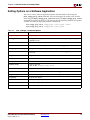
Conventions
This document uses the following conventions. An example illustrates each convention.
Typographical Conventions
The following typographical conventions are used in this document:
Convention
Meaning or Use
Example
Courier font
Messages, prompts, and program files that
the system displays
speed grade: - 100
Courier bold
Literal commands that you enter in a
syntactical statement. Descriptive text will
also reflect this convention.
ngdbuild <design_name>
Commands that you select from a menu
File > Open
Keyboard shortcuts
Ctrl+C
Helvetica bold
4
www.xilinx.com
Embedded System Tools Reference Manual
UG111, EDK 11.3.1
Conventions
Convention
Meaning or Use
Example
Variables in a code syntax statement for
which you must supply values. Text within
descriptions will also reflect this
convention.
ngdbuild <design_name>
References to other manuals
Refer To the Development System
Reference Guide for more information.
Emphasis in text
If a wire is drawn so that it overlaps the
pin of a symbol, the two nets are not
connected.
<Courier Italic in angle brackets>
Variable in a syntax statement for which you
must supply values within a Tcl file.
ngdbuild <design_name>
Square brackets
An optional entry or parameter. However, in
bus specifications, such as bus[7:0], they
are required.
ngdbuild [option_name]
<design_name>
A list of items from which you must choose
one or more
lowpwr ={on|off}
Separates items in a list of choices
lowpwr ={on|off}
Vertical ellipsis
Repetitive material that has been omitted
IOB #1: Name = QOUT’
IOB #2: Name = CLKIN’
Horizontal ellipsis . . .
Repetitive material that has been omitted
allow block block_name loc1 loc2 ...
locn;
Italic font
Braces
[ ]
{ }
Vertical bar
|
Online Document
The following conventions are used in this document:
Convention
Meaning or Use
Blue text
Cross-reference link to a location
in the current document
Blue, underlined text
Hyperlink to a website (URL)
Embedded System Tools Reference Manual
UG111, EDK 11.3.1
www.xilinx.com
Example
Refer to the section “Additional
Resources” for details.
Refer to “Title Formats” in
Chapter 1 for details.
Go to http://www.xilinx.com
for the latest speed files.
5
Preface: About This Guide
6
www.xilinx.com
Embedded System Tools Reference Manual
UG111, EDK 11.3.1
Table of Contents
Preface: About This Guide
Guide Contents . . . . . . . . . . . . . . . . . . . . . . . . . . . . . . . . . . . . . . . . . . . . . . . . . . . . . . . . . . . . . . 3
Additional Resources . . . . . . . . . . . . . . . . . . . . . . . . . . . . . . . . . . . . . . . . . . . . . . . . . . . . . . . . 4
Conventions . . . . . . . . . . . . . . . . . . . . . . . . . . . . . . . . . . . . . . . . . . . . . . . . . . . . . . . . . . . . . . . . . 4
Typographical Conventions . . . . . . . . . . . . . . . . . . . . . . . . . . . . . . . . . . . . . . . . . . . . . . . . . 4
Online Document . . . . . . . . . . . . . . . . . . . . . . . . . . . . . . . . . . . . . . . . . . . . . . . . . . . . . . . . . . 5
Chapter 1: Embedded System and Tools Architecture Overview
About EDK . . . . . . . . . . . . . . . . . . . . . . . . . . . . . . . . . . . . . . . . . . . . . . . . . . . . . . . . . . . . . . . . . 17
Additional Resources . . . . . . . . . . . . . . . . . . . . . . . . . . . . . . . . . . . . . . . . . . . . . . . . . . . . . . . 18
Design Process Overview . . . . . . . . . . . . . . . . . . . . . . . . . . . . . . . . . . . . . . . . . . . . . . . . . . . 18
Hardware Development . . . . . . . . . . . . . . . . . . . . . . . . . . . . . . . . . . . . . . . . . . . . . . . . . . .
Software Development . . . . . . . . . . . . . . . . . . . . . . . . . . . . . . . . . . . . . . . . . . . . . . . . . . . .
Verification . . . . . . . . . . . . . . . . . . . . . . . . . . . . . . . . . . . . . . . . . . . . . . . . . . . . . . . . . . . . . .
Hardware Verification Using Simulation . . . . . . . . . . . . . . . . . . . . . . . . . . . . . . . . . . . .
Software Verification Using Debugging . . . . . . . . . . . . . . . . . . . . . . . . . . . . . . . . . . . . .
Device Configuration . . . . . . . . . . . . . . . . . . . . . . . . . . . . . . . . . . . . . . . . . . . . . . . . . . . . .
18
19
19
19
19
19
EDK Overview . . . . . . . . . . . . . . . . . . . . . . . . . . . . . . . . . . . . . . . . . . . . . . . . . . . . . . . . . . . . . . 20
EDK Tools and Utilities . . . . . . . . . . . . . . . . . . . . . . . . . . . . . . . . . . . . . . . . . . . . . . . . . . . .
Xilinx Platform Studio (XPS) . . . . . . . . . . . . . . . . . . . . . . . . . . . . . . . . . . . . . . . . . . . . . . .
The Base System Builder (BSB) Wizard . . . . . . . . . . . . . . . . . . . . . . . . . . . . . . . . . . . . .
The Create and Import Peripheral (CIP) Wizard . . . . . . . . . . . . . . . . . . . . . . . . . . . . . .
Platform Specification Utility (PsfUtility) . . . . . . . . . . . . . . . . . . . . . . . . . . . . . . . . . . . .
Coprocessor Wizard . . . . . . . . . . . . . . . . . . . . . . . . . . . . . . . . . . . . . . . . . . . . . . . . . . . .
Platform Generator (Platgen) . . . . . . . . . . . . . . . . . . . . . . . . . . . . . . . . . . . . . . . . . . . . .
FXPS Command Line or “no window” Mode. . . . . . . . . . . . . . . . . . . . . . . . . . . . . . . . .
Bus Functional Model (BFM) . . . . . . . . . . . . . . . . . . . . . . . . . . . . . . . . . . . . . . . . . . . . .
Debug Configuration Wizard . . . . . . . . . . . . . . . . . . . . . . . . . . . . . . . . . . . . . . . . . . . . .
Simulation Model Generator (Simgen) . . . . . . . . . . . . . . . . . . . . . . . . . . . . . . . . . . . . . .
Software Development Kit (SDK) . . . . . . . . . . . . . . . . . . . . . . . . . . . . . . . . . . . . . . . . . . .
Library Generator (Libgen) . . . . . . . . . . . . . . . . . . . . . . . . . . . . . . . . . . . . . . . . . . . . . . .
GNU Compiler Tools (GCC) . . . . . . . . . . . . . . . . . . . . . . . . . . . . . . . . . . . . . . . . . . . . . .
Xilinx Microprocessor Debugger (XMD) . . . . . . . . . . . . . . . . . . . . . . . . . . . . . . . . . . . .
GNU Debugger (GDB) . . . . . . . . . . . . . . . . . . . . . . . . . . . . . . . . . . . . . . . . . . . . . . . . . .
Simulation Library Compiler (Compxlib) . . . . . . . . . . . . . . . . . . . . . . . . . . . . . . . . . . . .
Bitstream Initializer (Bitinit) . . . . . . . . . . . . . . . . . . . . . . . . . . . . . . . . . . . . . . . . . . . . . .
System ACE File Generator (GenACE) . . . . . . . . . . . . . . . . . . . . . . . . . . . . . . . . . . . . . .
Flash Memory Programmer . . . . . . . . . . . . . . . . . . . . . . . . . . . . . . . . . . . . . . . . . . . . . .
Format Revision Tool and Version Management Wizard . . . . . . . . . . . . . . . . . . . . . . . .
Xilinx Bash Shell . . . . . . . . . . . . . . . . . . . . . . . . . . . . . . . . . . . . . . . . . . . . . . . . . . . . . . .
21
22
23
23
24
24
24
24
25
25
25
25
26
26
27
27
27
27
27
28
28
28
Chapter 2: Platform Specification Utility (PsfUtility)
Tool Options . . . . . . . . . . . . . . . . . . . . . . . . . . . . . . . . . . . . . . . . . . . . . . . . . . . . . . . . . . . . . . . 30
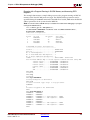
MPD Creation Process Overview . . . . . . . . . . . . . . . . . . . . . . . . . . . . . . . . . . . . . . . . . . . . 31
Embedded System Tools Reference Manual
UG111, EDK 11.3.1
www.xilinx.com
7
R
Use Models for Automatic MPD Creation. . . . . . . . . . . . . . . . . . . . . . . . . . . . . . . . . . . . 31
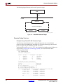
Peripherals with a Single Bus Interface . . . . . . . . . . . . . . . . . . . . . . . . . . . . . . . . . . . . . .
Signal Naming Conventions . . . . . . . . . . . . . . . . . . . . . . . . . . . . . . . . . . . . . . . . . . . . . .
Invoking the PsfUtility . . . . . . . . . . . . . . . . . . . . . . . . . . . . . . . . . . . . . . . . . . . . . . . . . .
Peripherals with Multiple Bus Interfaces . . . . . . . . . . . . . . . . . . . . . . . . . . . . . . . . . . . . .
Non-Exclusive and Exclusive Bus Interfaces . . . . . . . . . . . . . . . . . . . . . . . . . . . . . . . . .
Peripherals with Point-to-Point Connections . . . . . . . . . . . . . . . . . . . . . . . . . . . . . . . . .
32
32
32
32
32
33
DRC Checks in PsfUtility . . . . . . . . . . . . . . . . . . . . . . . . . . . . . . . . . . . . . . . . . . . . . . . . . . . 34
HDL Source Errors . . . . . . . . . . . . . . . . . . . . . . . . . . . . . . . . . . . . . . . . . . . . . . . . . . . . . . . . 34
Bus Interface Checks . . . . . . . . . . . . . . . . . . . . . . . . . . . . . . . . . . . . . . . . . . . . . . . . . . . . . . 34
Conventions for Defining HDL Peripherals . . . . . . . . . . . . . . . . . . . . . . . . . . . . . . . . . 34
Naming Conventions for Bus Interfaces . . . . . . . . . . . . . . . . . . . . . . . . . . . . . . . . . . . . . .
Naming Conventions for VHDL Generics . . . . . . . . . . . . . . . . . . . . . . . . . . . . . . . . . . . .
Reserved Parameters . . . . . . . . . . . . . . . . . . . . . . . . . . . . . . . . . . . . . . . . . . . . . . . . . . . . . .
Naming Conventions for Bus Interface Signals . . . . . . . . . . . . . . . . . . . . . . . . . . . . . . . .
Global Ports . . . . . . . . . . . . . . . . . . . . . . . . . . . . . . . . . . . . . . . . . . . . . . . . . . . . . . . . . . . . . .
Slave DCR Ports . . . . . . . . . . . . . . . . . . . . . . . . . . . . . . . . . . . . . . . . . . . . . . . . . . . . . . . . . .
Slave FSL Ports . . . . . . . . . . . . . . . . . . . . . . . . . . . . . . . . . . . . . . . . . . . . . . . . . . . . . . . . . . .
Master FSL Ports . . . . . . . . . . . . . . . . . . . . . . . . . . . . . . . . . . . . . . . . . . . . . . . . . . . . . . . . .
Slave LMB Ports . . . . . . . . . . . . . . . . . . . . . . . . . . . . . . . . . . . . . . . . . . . . . . . . . . . . . . . . . .
Master OPB Ports . . . . . . . . . . . . . . . . . . . . . . . . . . . . . . . . . . . . . . . . . . . . . . . . . . . . . . . . .
Slave OPB Ports . . . . . . . . . . . . . . . . . . . . . . . . . . . . . . . . . . . . . . . . . . . . . . . . . . . . . . . . . .
Master/Slave OPB Ports . . . . . . . . . . . . . . . . . . . . . . . . . . . . . . . . . . . . . . . . . . . . . . . . . . .
Master PLB Ports . . . . . . . . . . . . . . . . . . . . . . . . . . . . . . . . . . . . . . . . . . . . . . . . . . . . . . . . .
PLB Master Outputs . . . . . . . . . . . . . . . . . . . . . . . . . . . . . . . . . . . . . . . . . . . . . . . . . . . .
PLB Master Inputs . . . . . . . . . . . . . . . . . . . . . . . . . . . . . . . . . . . . . . . . . . . . . . . . . . . . .
Slave PLB Ports . . . . . . . . . . . . . . . . . . . . . . . . . . . . . . . . . . . . . . . . . . . . . . . . . . . . . . . . . . .
PLB Slave Outputs . . . . . . . . . . . . . . . . . . . . . . . . . . . . . . . . . . . . . . . . . . . . . . . . . . . . .
PLB Slave Inputs . . . . . . . . . . . . . . . . . . . . . . . . . . . . . . . . . . . . . . . . . . . . . . . . . . . . . . .
Master PLBV4.6 ports . . . . . . . . . . . . . . . . . . . . . . . . . . . . . . . . . . . . . . . . . . . . . . . . . . . . .
PLB v4.6 Master Outputs . . . . . . . . . . . . . . . . . . . . . . . . . . . . . . . . . . . . . . . . . . . . . . . .
PLB v4.6 Master Inputs . . . . . . . . . . . . . . . . . . . . . . . . . . . . . . . . . . . . . . . . . . . . . . . . . .
Slave PLBV46 ports . . . . . . . . . . . . . . . . . . . . . . . . . . . . . . . . . . . . . . . . . . . . . . . . . . . . . . .
PLBV46 Slave Outputs . . . . . . . . . . . . . . . . . . . . . . . . . . . . . . . . . . . . . . . . . . . . . . . . . .
PLBV4.6 Slave Inputs . . . . . . . . . . . . . . . . . . . . . . . . . . . . . . . . . . . . . . . . . . . . . . . . . . .
35
36
38
39
40
40
41
42
43
44
45
46
47
48
48
49
49
50
50
51
51
52
52
53
Chapter 3: Platform Generator (Platgen)
Features . . . . . . . . . . . . . . . . . . . . . . . . . . . . . . . . . . . . . . . . . . . . . . . . . . . . . . . . . . . . . . . . . . . . .
Additional Resources . . . . . . . . . . . . . . . . . . . . . . . . . . . . . . . . . . . . . . . . . . . . . . . . . . . . . . .
Tool Requirements . . . . . . . . . . . . . . . . . . . . . . . . . . . . . . . . . . . . . . . . . . . . . . . . . . . . . . . . . .
Tool Usage . . . . . . . . . . . . . . . . . . . . . . . . . . . . . . . . . . . . . . . . . . . . . . . . . . . . . . . . . . . . . . . . . .
Tool Options . . . . . . . . . . . . . . . . . . . . . . . . . . . . . . . . . . . . . . . . . . . . . . . . . . . . . . . . . . . . . . . .
Load Path . . . . . . . . . . . . . . . . . . . . . . . . . . . . . . . . . . . . . . . . . . . . . . . . . . . . . . . . . . . . . . . . . . .
Output Files . . . . . . . . . . . . . . . . . . . . . . . . . . . . . . . . . . . . . . . . . . . . . . . . . . . . . . . . . . . . . . . .
HDL Directory . . . . . . . . . . . . . . . . . . . . . . . . . . . . . . . . . . . . . . . . . . . . . . . . . . . . . . . . . . .
Implementation Directory . . . . . . . . . . . . . . . . . . . . . . . . . . . . . . . . . . . . . . . . . . . . . . . . .
Synthesis Directory . . . . . . . . . . . . . . . . . . . . . . . . . . . . . . . . . . . . . . . . . . . . . . . . . . . . . . .
BMM Flow . . . . . . . . . . . . . . . . . . . . . . . . . . . . . . . . . . . . . . . . . . . . . . . . . . . . . . . . . . . . . . .
55
56
56
56
56
57
58
58
58
58
59
Synthesis Netlist Cache . . . . . . . . . . . . . . . . . . . . . . . . . . . . . . . . . . . . . . . . . . . . . . . . . . . . . 59
8
www.xilinx.com
Embedded System Tools Reference Manual
UG111, EDK 11.3.1
R
Chapter 4: Command Line (no window) Mode
Invoking XPS Command Line Mode . . . . . . . . . . . . . . . . . . . . . . . . . . . . . . . . . . . . . . . . .
Creating a New Empty Project . . . . . . . . . . . . . . . . . . . . . . . . . . . . . . . . . . . . . . . . . . . . . . .
Creating a New Project With an Existing MHS . . . . . . . . . . . . . . . . . . . . . . . . . . . . . . .
Opening an Existing Project . . . . . . . . . . . . . . . . . . . . . . . . . . . . . . . . . . . . . . . . . . . . . . . . .
Reading an MSS File . . . . . . . . . . . . . . . . . . . . . . . . . . . . . . . . . . . . . . . . . . . . . . . . . . . . . . . .
Saving Your Project Files . . . . . . . . . . . . . . . . . . . . . . . . . . . . . . . . . . . . . . . . . . . . . . . . . . . .
Setting Project Options . . . . . . . . . . . . . . . . . . . . . . . . . . . . . . . . . . . . . . . . . . . . . . . . . . . . . .
Executing Flow Commands . . . . . . . . . . . . . . . . . . . . . . . . . . . . . . . . . . . . . . . . . . . . . . . . . .
Reloading an MHS File . . . . . . . . . . . . . . . . . . . . . . . . . . . . . . . . . . . . . . . . . . . . . . . . . . . . .
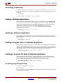
Adding a Software Application . . . . . . . . . . . . . . . . . . . . . . . . . . . . . . . . . . . . . . . . . . . . . .
Deleting a Software Application. . . . . . . . . . . . . . . . . . . . . . . . . . . . . . . . . . . . . . . . . . . . .
Adding a Program File to a Software Application . . . . . . . . . . . . . . . . . . . . . . . . . . . .
Deleting a Program File from a Software Application . . . . . . . . . . . . . . . . . . . . . . . .
Archiving Your Project Files . . . . . . . . . . . . . . . . . . . . . . . . . . . . . . . . . . . . . . . . . . . . . . . . .
Setting Options on a Software Application . . . . . . . . . . . . . . . . . . . . . . . . . . . . . . . . . .
Settings on Special Software Applications . . . . . . . . . . . . . . . . . . . . . . . . . . . . . . . . . . .
Restrictions . . . . . . . . . . . . . . . . . . . . . . . . . . . . . . . . . . . . . . . . . . . . . . . . . . . . . . . . . . . . . . . . .
62
62
62
63
63
63
63
64
66
66
66
66
66
66
67
68
68
MSS Changes . . . . . . . . . . . . . . . . . . . . . . . . . . . . . . . . . . . . . . . . . . . . . . . . . . . . . . . . . . . . 68
XMP Changes . . . . . . . . . . . . . . . . . . . . . . . . . . . . . . . . . . . . . . . . . . . . . . . . . . . . . . . . . . . . 68
Chapter 5: Bus Functional Model Simulation
Introduction . . . . . . . . . . . . . . . . . . . . . . . . . . . . . . . . . . . . . . . . . . . . . . . . . . . . . . . . . . . . . . . . 69
Bus Functional Simulation Basics . . . . . . . . . . . . . . . . . . . . . . . . . . . . . . . . . . . . . . . . . . . 69
Bus Functional Models (BFMs) . . . . . . . . . . . . . . . . . . . . . . . . . . . . . . . . . . . . . . . . . . . . . 70
Bus Functional Language (BFL) . . . . . . . . . . . . . . . . . . . . . . . . . . . . . . . . . . . . . . . . . . . . . 70
Bus Functional Compiler (BFC) . . . . . . . . . . . . . . . . . . . . . . . . . . . . . . . . . . . . . . . . . . . . . 70
Bus Functional Model Use Cases . . . . . . . . . . . . . . . . . . . . . . . . . . . . . . . . . . . . . . . . . . . . 70
IP Verification . . . . . . . . . . . . . . . . . . . . . . . . . . . . . . . . . . . . . . . . . . . . . . . . . . . . . . . . . . . . 70
Speed-Up Simulation. . . . . . . . . . . . . . . . . . . . . . . . . . . . . . . . . . . . . . . . . . . . . . . . . . . . . . 71
Bus Functional Simulation Methods . . . . . . . . . . . . . . . . . . . . . . . . . . . . . . . . . . . . . . . . . 72
IBM CoreConnect Toolkit . . . . . . . . . . . . . . . . . . . . . . . . . . . . . . . . . . . . . . . . . . . . . . . . . . 73
Platform Studio BFM Package . . . . . . . . . . . . . . . . . . . . . . . . . . . . . . . . . . . . . . . . . . . . . . 73
Getting and Installing the Platform Studio BFM Package . . . . . . . . . . . . . . . . . . . . 73
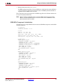
Using the Platform Studio BFM Package . . . . . . . . . . . . . . . . . . . . . . . . . . . . . . . . . . . . . 74
OPB BFM Component Instantiation . . . . . . . . . . . . . . . . . . . . . . . . . . . . . . . . . . . . . . . . . 75
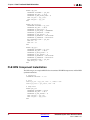
PLB BFM Component Instantiation . . . . . . . . . . . . . . . . . . . . . . . . . . . . . . . . . . . . . . . . . . 76
PLB v4.6 BFM Component Instantiation . . . . . . . . . . . . . . . . . . . . . . . . . . . . . . . . . . . . .
BFM Synchronization Bus Usage . . . . . . . . . . . . . . . . . . . . . . . . . . . . . . . . . . . . . . . . . . . .
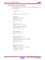
OPB Bus Functional Language Usage . . . . . . . . . . . . . . . . . . . . . . . . . . . . . . . . . . . . . . . .
PLB Bus Functional Language Usage . . . . . . . . . . . . . . . . . . . . . . . . . . . . . . . . . . . . . . . .
Bus Functional Compiler Usage . . . . . . . . . . . . . . . . . . . . . . . . . . . . . . . . . . . . . . . . . . . .
Running BFM Simulations . . . . . . . . . . . . . . . . . . . . . . . . . . . . . . . . . . . . . . . . . . . . . . . . .
78
79
80
81
82
83
Chapter 6: Simulation Model Generator (Simgen)
Simgen Overview . . . . . . . . . . . . . . . . . . . . . . . . . . . . . . . . . . . . . . . . . . . . . . . . . . . . . . . . . . . 85
Embedded System Tools Reference Manual
UG111, EDK 11.3.1
www.xilinx.com
9
R
Additional Resources . . . . . . . . . . . . . . . . . . . . . . . . . . . . . . . . . . . . . . . . . . . . . . . . . . . . . . . 85
Simulation Libraries . . . . . . . . . . . . . . . . . . . . . . . . . . . . . . . . . . . . . . . . . . . . . . . . . . . . . . . . 86
Xilinx ISE Libraries . . . . . . . . . . . . . . . . . . . . . . . . . . . . . . . . . . . . . . . . . . . . . . . . . . . . . . .
UNISIM Library . . . . . . . . . . . . . . . . . . . . . . . . . . . . . . . . . . . . . . . . . . . . . . . . . . . . . . .
SIMPRIM Library . . . . . . . . . . . . . . . . . . . . . . . . . . . . . . . . . . . . . . . . . . . . . . . . . . . . . .
XilinxCoreLib Library . . . . . . . . . . . . . . . . . . . . . . . . . . . . . . . . . . . . . . . . . . . . . . . . . . .
Xilinx EDK Library . . . . . . . . . . . . . . . . . . . . . . . . . . . . . . . . . . . . . . . . . . . . . . . . . . . . . . .
EDK Libraries Search Order . . . . . . . . . . . . . . . . . . . . . . . . . . . . . . . . . . . . . . . . . . . . . .
86
86
86
87
87
87
Compxlib Utility . . . . . . . . . . . . . . . . . . . . . . . . . . . . . . . . . . . . . . . . . . . . . . . . . . . . . . . . . . . . 87
Simulation Models . . . . . . . . . . . . . . . . . . . . . . . . . . . . . . . . . . . . . . . . . . . . . . . . . . . . . . . . . . 88
Behavioral Models . . . . . . . . . . . . . . . . . . . . . . . . . . . . . . . . . . . . . . . . . . . . . . . . . . . . . . . .
Structural Models . . . . . . . . . . . . . . . . . . . . . . . . . . . . . . . . . . . . . . . . . . . . . . . . . . . . . . . . .
Timing Models . . . . . . . . . . . . . . . . . . . . . . . . . . . . . . . . . . . . . . . . . . . . . . . . . . . . . . . . . . .
Single and Mixed Language Models . . . . . . . . . . . . . . . . . . . . . . . . . . . . . . . . . . . . . . . . .
Creating Simulation Models Using XPS Batch Mode . . . . . . . . . . . . . . . . . . . . . . . . . . .
88
89
89
90
90
Simgen Syntax . . . . . . . . . . . . . . . . . . . . . . . . . . . . . . . . . . . . . . . . . . . . . . . . . . . . . . . . . . . . . . 91
Requirements . . . . . . . . . . . . . . . . . . . . . . . . . . . . . . . . . . . . . . . . . . . . . . . . . . . . . . . . . . . . 91
Options . . . . . . . . . . . . . . . . . . . . . . . . . . . . . . . . . . . . . . . . . . . . . . . . . . . . . . . . . . . . . . . . . 91
Output Files . . . . . . . . . . . . . . . . . . . . . . . . . . . . . . . . . . . . . . . . . . . . . . . . . . . . . . . . . . . . . . . . 93
Memory Initialization . . . . . . . . . . . . . . . . . . . . . . . . . . . . . . . . . . . . . . . . . . . . . . . . . . . . . . . 94
VHDL . . . . . . . . . . . . . . . . . . . . . . . . . . . . . . . . . . . . . . . . . . . . . . . . . . . . . . . . . . . . . . . . . . . 94
Verilog . . . . . . . . . . . . . . . . . . . . . . . . . . . . . . . . . . . . . . . . . . . . . . . . . . . . . . . . . . . . . . . . . . 94
Test Benches . . . . . . . . . . . . . . . . . . . . . . . . . . . . . . . . . . . . . . . . . . . . . . . . . . . . . . . . . . . . . . . . 94
VHDL Test Bench Example. . . . . . . . . . . . . . . . . . . . . . . . . . . . . . . . . . . . . . . . . . . . . . . 95
Verilog Test Bench Example . . . . . . . . . . . . . . . . . . . . . . . . . . . . . . . . . . . . . . . . . . . . . . 96
Simulating Your Design . . . . . . . . . . . . . . . . . . . . . . . . . . . . . . . . . . . . . . . . . . . . . . . . . . . . . 98
Restrictions . . . . . . . . . . . . . . . . . . . . . . . . . . . . . . . . . . . . . . . . . . . . . . . . . . . . . . . . . . . . . . . . . 98
Chapter 7: Library Generator (Libgen)
Overview . . . . . . . . . . . . . . . . . . . . . . . . . . . . . . . . . . . . . . . . . . . . . . . . . . . . . . . . . . . . . . . . . . . 99
Additional Resources . . . . . . . . . . . . . . . . . . . . . . . . . . . . . . . . . . . . . . . . . . . . . . . . . . . . . . 100
Tool Usage . . . . . . . . . . . . . . . . . . . . . . . . . . . . . . . . . . . . . . . . . . . . . . . . . . . . . . . . . . . . . . . . . 100
Tool Options . . . . . . . . . . . . . . . . . . . . . . . . . . . . . . . . . . . . . . . . . . . . . . . . . . . . . . . . . . . . . . . 100
Load Paths . . . . . . . . . . . . . . . . . . . . . . . . . . . . . . . . . . . . . . . . . . . . . . . . . . . . . . . . . . . . . . . . . 102
PC System Load Paths . . . . . . . . . . . . . . . . . . . . . . . . . . . . . . . . . . . . . . . . . . . . . . . . . . . . 102
Additional Directories . . . . . . . . . . . . . . . . . . . . . . . . . . . . . . . . . . . . . . . . . . . . . . . . . . . . 102
Search Priority Mechanism . . . . . . . . . . . . . . . . . . . . . . . . . . . . . . . . . . . . . . . . . . . . . . . . 103
Output Files . . . . . . . . . . . . . . . . . . . . . . . . . . . . . . . . . . . . . . . . . . . . . . . . . . . . . . . . . . . . . . . 104
include Directory . . . . . . . . . . . . . . . . . . . . . . . . . . . . . . . . . . . . . . . . . . . . . . . . . . . . . . . .
lib Directory . . . . . . . . . . . . . . . . . . . . . . . . . . . . . . . . . . . . . . . . . . . . . . . . . . . . . . . . . . . .
libsrc Directory . . . . . . . . . . . . . . . . . . . . . . . . . . . . . . . . . . . . . . . . . . . . . . . . . . . . . . . . . .
code Directory . . . . . . . . . . . . . . . . . . . . . . . . . . . . . . . . . . . . . . . . . . . . . . . . . . . . . . . . . .
104
104
104
104
Generating Libraries and Drivers . . . . . . . . . . . . . . . . . . . . . . . . . . . . . . . . . . . . . . . . . . . 105
Overview . . . . . . . . . . . . . . . . . . . . . . . . . . . . . . . . . . . . . . . . . . . . . . . . . . . . . . . . . . . . . . . 105
MDD, MLD, and Tcl . . . . . . . . . . . . . . . . . . . . . . . . . . . . . . . . . . . . . . . . . . . . . . . . . . . . . 105
MSS Parameters. . . . . . . . . . . . . . . . . . . . . . . . . . . . . . . . . . . . . . . . . . . . . . . . . . . . . . . . . . . . 106
Drivers. . . . . . . . . . . . . . . . . . . . . . . . . . . . . . . . . . . . . . . . . . . . . . . . . . . . . . . . . . . . . . . . . . . . . 106
Libraries . . . . . . . . . . . . . . . . . . . . . . . . . . . . . . . . . . . . . . . . . . . . . . . . . . . . . . . . . . . . . . . . . . . 107
10
www.xilinx.com
Embedded System Tools Reference Manual
UG111, EDK 11.3.1
R
OS Block . . . . . . . . . . . . . . . . . . . . . . . . . . . . . . . . . . . . . . . . . . . . . . . . . . . . . . . . . . . . . . . . . . . 107
Chapter 8: GNU Compiler Tools
Overview . . . . . . . . . . . . . . . . . . . . . . . . . . . . . . . . . . . . . . . . . . . . . . . . . . . . . . . . . . . . . . . . . .
Additional Resources . . . . . . . . . . . . . . . . . . . . . . . . . . . . . . . . . . . . . . . . . . . . . . . . . . . . . .
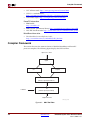
Compiler Framework. . . . . . . . . . . . . . . . . . . . . . . . . . . . . . . . . . . . . . . . . . . . . . . . . . . . . . .
Common Compiler Usage and Options . . . . . . . . . . . . . . . . . . . . . . . . . . . . . . . . . . . . .
Usage . . . . . . . . . . . . . . . . . . . . . . . . . . . . . . . . . . . . . . . . . . . . . . . . . . . . . . . . . . . . . . . . . .
Input Files . . . . . . . . . . . . . . . . . . . . . . . . . . . . . . . . . . . . . . . . . . . . . . . . . . . . . . . . . . . . . .
Output Files . . . . . . . . . . . . . . . . . . . . . . . . . . . . . . . . . . . . . . . . . . . . . . . . . . . . . . . . . . . .
File Types and Extensions . . . . . . . . . . . . . . . . . . . . . . . . . . . . . . . . . . . . . . . . . . . . . . . .
Libraries . . . . . . . . . . . . . . . . . . . . . . . . . . . . . . . . . . . . . . . . . . . . . . . . . . . . . . . . . . . . . . . .
Language Dialect . . . . . . . . . . . . . . . . . . . . . . . . . . . . . . . . . . . . . . . . . . . . . . . . . . . . . . . .
Commonly Used Compiler Options: Quick Reference . . . . . . . . . . . . . . . . . . . . . . . .
General Options . . . . . . . . . . . . . . . . . . . . . . . . . . . . . . . . . . . . . . . . . . . . . . . . . . . . . . . . .
Library Search Options . . . . . . . . . . . . . . . . . . . . . . . . . . . . . . . . . . . . . . . . . . . . . . . . . . .
Header File Search Option . . . . . . . . . . . . . . . . . . . . . . . . . . . . . . . . . . . . . . . . . . . . . . . .
Default Search Paths . . . . . . . . . . . . . . . . . . . . . . . . . . . . . . . . . . . . . . . . . . . . . . . . . . . . .
Linker Options . . . . . . . . . . . . . . . . . . . . . . . . . . . . . . . . . . . . . . . . . . . . . . . . . . . . . . . . . .
Memory Layout . . . . . . . . . . . . . . . . . . . . . . . . . . . . . . . . . . . . . . . . . . . . . . . . . . . . . . . . .
Reserved Memory . . . . . . . . . . . . . . . . . . . . . . . . . . . . . . . . . . . . . . . . . . . . . . . . . . . . .
I/O Memory . . . . . . . . . . . . . . . . . . . . . . . . . . . . . . . . . . . . . . . . . . . . . . . . . . . . . . . . .
User and Program Memory . . . . . . . . . . . . . . . . . . . . . . . . . . . . . . . . . . . . . . . . . . . . .
Object-File Sections . . . . . . . . . . . . . . . . . . . . . . . . . . . . . . . . . . . . . . . . . . . . . . . . . . . . . .
Linker Scripts . . . . . . . . . . . . . . . . . . . . . . . . . . . . . . . . . . . . . . . . . . . . . . . . . . . . . . . . . . .
109
109
110
112
112
112
112
113
113
114
115
115
118
118
118
120
120
120
121
121
122
125
MicroBlaze Compiler Usage and Options . . . . . . . . . . . . . . . . . . . . . . . . . . . . . . . . . . . 126
MicroBlaze Compiler . . . . . . . . . . . . . . . . . . . . . . . . . . . . . . . . . . . . . . . . . . . . . . . . . . . . .
MicroBlaze Compiler Options: Quick Reference . . . . . . . . . . . . . . . . . . . . . . . . . . . . .
Processor Feature Selection Options . . . . . . . . . . . . . . . . . . . . . . . . . . . . . . . . . . . . . . . .
General Program Options . . . . . . . . . . . . . . . . . . . . . . . . . . . . . . . . . . . . . . . . . . . . . . . . .
Application Execution Modes . . . . . . . . . . . . . . . . . . . . . . . . . . . . . . . . . . . . . . . . . . . .
Position Independent Code . . . . . . . . . . . . . . . . . . . . . . . . . . . . . . . . . . . . . . . . . . . . .
MicroBlaze Application Binary Interface . . . . . . . . . . . . . . . . . . . . . . . . . . . . . . . . . . . .
MicroBlaze Assembler . . . . . . . . . . . . . . . . . . . . . . . . . . . . . . . . . . . . . . . . . . . . . . . . . . . .
MicroBlaze Linker Options . . . . . . . . . . . . . . . . . . . . . . . . . . . . . . . . . . . . . . . . . . . . . . . .
MicroBlaze Linker Script Sections . . . . . . . . . . . . . . . . . . . . . . . . . . . . . . . . . . . . . . . . . .
Tips for Writing or Customizing Linker Scripts . . . . . . . . . . . . . . . . . . . . . . . . . . . . . .
Startup Files . . . . . . . . . . . . . . . . . . . . . . . . . . . . . . . . . . . . . . . . . . . . . . . . . . . . . . . . . . . .
First Stage Initialization Files . . . . . . . . . . . . . . . . . . . . . . . . . . . . . . . . . . . . . . . . . . . .
Second Stage Initialization Files . . . . . . . . . . . . . . . . . . . . . . . . . . . . . . . . . . . . . . . . . .
Other files . . . . . . . . . . . . . . . . . . . . . . . . . . . . . . . . . . . . . . . . . . . . . . . . . . . . . . . . . . .
Modifying Startup Files . . . . . . . . . . . . . . . . . . . . . . . . . . . . . . . . . . . . . . . . . . . . . . . . . .
Reducing the Startup Code Size for C Programs . . . . . . . . . . . . . . . . . . . . . . . . . . . . .
Compiler Libraries . . . . . . . . . . . . . . . . . . . . . . . . . . . . . . . . . . . . . . . . . . . . . . . . . . . . . . .
Thread Safety . . . . . . . . . . . . . . . . . . . . . . . . . . . . . . . . . . . . . . . . . . . . . . . . . . . . . . . . . . .
Command Line Arguments . . . . . . . . . . . . . . . . . . . . . . . . . . . . . . . . . . . . . . . . . . . . . . .
Interrupt Handlers . . . . . . . . . . . . . . . . . . . . . . . . . . . . . . . . . . . . . . . . . . . . . . . . . . . . . . .
126
126
126
129
130
131
131
131
133
134
135
135
136
137
138
138
139
139
140
140
141
PowerPC Compiler Usage and Options . . . . . . . . . . . . . . . . . . . . . . . . . . . . . . . . . . . . . 142
PowerPC Compiler Options: Quick Reference . . . . . . . . . . . . . . . . . . . . . . . . . . . . . . .
PowerPC Compiler Options . . . . . . . . . . . . . . . . . . . . . . . . . . . . . . . . . . . . . . . . . . . . . . .
PowerPC Processor Linker . . . . . . . . . . . . . . . . . . . . . . . . . . . . . . . . . . . . . . . . . . . . . . . .
PowerPC Processor Linker Script Sections . . . . . . . . . . . . . . . . . . . . . . . . . . . . . . . . . .
Embedded System Tools Reference Manual
UG111, EDK 11.3.1
www.xilinx.com
142
142
144
144
11
R
Tips for Writing or Customizing Linker Scripts . . . . . . . . . . . . . . . . . . . . . . . . . . . . . .
Startup Files . . . . . . . . . . . . . . . . . . . . . . . . . . . . . . . . . . . . . . . . . . . . . . . . . . . . . . . . . . . .
Initialization File Description . . . . . . . . . . . . . . . . . . . . . . . . . . . . . . . . . . . . . . . . . . . .
Start-up File Descriptions . . . . . . . . . . . . . . . . . . . . . . . . . . . . . . . . . . . . . . . . . . . . . . .
Other files . . . . . . . . . . . . . . . . . . . . . . . . . . . . . . . . . . . . . . . . . . . . . . . . . . . . . . . . . . .
Modifying Startup Files . . . . . . . . . . . . . . . . . . . . . . . . . . . . . . . . . . . . . . . . . . . . . . . . . .
Reducing the Startup Code Size for C Programs . . . . . . . . . . . . . . . . . . . . . . . . . . . . .
Modifying Startup Files for Bootstrapping an Application. . . . . . . . . . . . . . . . . . . . . .
Compiler Libraries . . . . . . . . . . . . . . . . . . . . . . . . . . . . . . . . . . . . . . . . . . . . . . . . . . . . . . .
Thread Safety . . . . . . . . . . . . . . . . . . . . . . . . . . . . . . . . . . . . . . . . . . . . . . . . . . . . . . . . . . .
Command Line Arguments . . . . . . . . . . . . . . . . . . . . . . . . . . . . . . . . . . . . . . . . . . . . . . .
145
146
147
147
147
148
148
149
149
149
149
Other Notes . . . . . . . . . . . . . . . . . . . . . . . . . . . . . . . . . . . . . . . . . . . . . . . . . . . . . . . . . . . . . . . . 150
C++ Code Size . . . . . . . . . . . . . . . . . . . . . . . . . . . . . . . . . . . . . . . . . . . . . . . . . . . . . . .
C++ Standard Library . . . . . . . . . . . . . . . . . . . . . . . . . . . . . . . . . . . . . . . . . . . . . . . . . .
Position Independent Code (Relocatable Code) . . . . . . . . . . . . . . . . . . . . . . . . . . . . . .
Other Switches and Features . . . . . . . . . . . . . . . . . . . . . . . . . . . . . . . . . . . . . . . . . . . .
150
150
150
150
Chapter 9: Xilinx Microprocessor Debugger (XMD)
Additional Resources . . . . . . . . . . . . . . . . . . . . . . . . . . . . . . . . . . . . . . . . . . . . . . . . . . . . . .
XMD Usage . . . . . . . . . . . . . . . . . . . . . . . . . . . . . . . . . . . . . . . . . . . . . . . . . . . . . . . . . . . . . . . .
XMD Console . . . . . . . . . . . . . . . . . . . . . . . . . . . . . . . . . . . . . . . . . . . . . . . . . . . . . . . . . . . . . .
XMD Command Reference . . . . . . . . . . . . . . . . . . . . . . . . . . . . . . . . . . . . . . . . . . . . . . . .
152
152
154
154
XMD User Command Summary . . . . . . . . . . . . . . . . . . . . . . . . . . . . . . . . . . . . . . . . . . . 154
XMD User Commands . . . . . . . . . . . . . . . . . . . . . . . . . . . . . . . . . . . . . . . . . . . . . . . . . . . . . 155
Special Purpose Register Names . . . . . . . . . . . . . . . . . . . . . . . . . . . . . . . . . . . . . . . . . . .
MicroBlaze Special Purpose Register Names . . . . . . . . . . . . . . . . . . . . . . . . . . . . . . . .
PowerPC 405 Processor Special Purpose Register Names . . . . . . . . . . . . . . . . . . . . . .
PowerPC 440 Processor Special Purpose Register Names . . . . . . . . . . . . . . . . . . . . . .
XMD Reset Sequence . . . . . . . . . . . . . . . . . . . . . . . . . . . . . . . . . . . . . . . . . . . . . . . . . . . . .
PowerPC 405 Processors . . . . . . . . . . . . . . . . . . . . . . . . . . . . . . . . . . . . . . . . . . . . . . . .
PowerPC 440 Processors . . . . . . . . . . . . . . . . . . . . . . . . . . . . . . . . . . . . . . . . . . . . . . . .
MicroBlaze . . . . . . . . . . . . . . . . . . . . . . . . . . . . . . . . . . . . . . . . . . . . . . . . . . . . . . . . . .
Recommended XMD Flows . . . . . . . . . . . . . . . . . . . . . . . . . . . . . . . . . . . . . . . . . . . . . . .
Debugging a Program . . . . . . . . . . . . . . . . . . . . . . . . . . . . . . . . . . . . . . . . . . . . . . . . . . . .
Debugging Programs in a Multi-processor Environment . . . . . . . . . . . . . . . . . . . . . .
Running a Program in a Debug Session . . . . . . . . . . . . . . . . . . . . . . . . . . . . . . . . . . . . .
Using Safemode for Automatic Exception Trapping . . . . . . . . . . . . . . . . . . . . . . . . . .
Processor Default Exception Settings . . . . . . . . . . . . . . . . . . . . . . . . . . . . . . . . . . . . . . .
Overwriting Exception Settings . . . . . . . . . . . . . . . . . . . . . . . . . . . . . . . . . . . . . . . . . . . .
Viewing Safemode Settings . . . . . . . . . . . . . . . . . . . . . . . . . . . . . . . . . . . . . . . . . . . . . . .
160
160
161
162
162
163
163
163
164
164
164
165
165
165
167
167
Connect Command Options . . . . . . . . . . . . . . . . . . . . . . . . . . . . . . . . . . . . . . . . . . . . . . . . 168
Usage . . . . . . . . . . . . . . . . . . . . . . . . . . . . . . . . . . . . . . . . . . . . . . . . . . . . . . . . . . . . . .
PowerPC Processor Targets . . . . . . . . . . . . . . . . . . . . . . . . . . . . . . . . . . . . . . . . . . . . . . .
PowerPC Processor Hardware Connection . . . . . . . . . . . . . . . . . . . . . . . . . . . . . . . . .
PowerPC Processor Target Requirements. . . . . . . . . . . . . . . . . . . . . . . . . . . . . . . . . . .
Example Debug Sessions . . . . . . . . . . . . . . . . . . . . . . . . . . . . . . . . . . . . . . . . . . . . . . .
Example Connecting to PowerPC440 Processor Target . . . . . . . . . . . . . . . . . . . . . . . .
PowerPC Processor Simulator Target . . . . . . . . . . . . . . . . . . . . . . . . . . . . . . . . . . . . . .
Running PowerPC Processor ISS . . . . . . . . . . . . . . . . . . . . . . . . . . . . . . . . . . . . . . . . .
Example Debug Session for PowerPC Processor ISS Target . . . . . . . . . . . . . . . . . . . . .
DCR, TLB, and Cache Address Space and Access . . . . . . . . . . . . . . . . . . . . . . . . . . . .
12
www.xilinx.com
168
168
168
171
172
174
176
177
178
179
Embedded System Tools Reference Manual
UG111, EDK 11.3.1
R
Advanced PowerPC Processor Debugging Tips . . . . . . . . . . . . . . . . . . . . . . . . . . . . . .
MicroBlaze Processor Target . . . . . . . . . . . . . . . . . . . . . . . . . . . . . . . . . . . . . . . . . . . . . .
MicroBlaze MDM Hardware Target . . . . . . . . . . . . . . . . . . . . . . . . . . . . . . . . . . . . . . .
MicroBlaze MDM Target Requirements . . . . . . . . . . . . . . . . . . . . . . . . . . . . . . . . . . . .
Example Debug Sessions . . . . . . . . . . . . . . . . . . . . . . . . . . . . . . . . . . . . . . . . . . . . . . .
MicroBlaze Stub Hardware Target . . . . . . . . . . . . . . . . . . . . . . . . . . . . . . . . . . . . . . . .
MicroBlaze Stub-JTAG Target Options . . . . . . . . . . . . . . . . . . . . . . . . . . . . . . . . . . . . .
MicroBlaze Stub-Serial Target Options . . . . . . . . . . . . . . . . . . . . . . . . . . . . . . . . . . . . .
Stub Target Requirements. . . . . . . . . . . . . . . . . . . . . . . . . . . . . . . . . . . . . . . . . . . . . . .
MicroBlaze Simulator Target . . . . . . . . . . . . . . . . . . . . . . . . . . . . . . . . . . . . . . . . . . . .
Simulator Target Requirements . . . . . . . . . . . . . . . . . . . . . . . . . . . . . . . . . . . . . . . . . .
MDM Peripheral Target . . . . . . . . . . . . . . . . . . . . . . . . . . . . . . . . . . . . . . . . . . . . . . . .
Configure Debug Session . . . . . . . . . . . . . . . . . . . . . . . . . . . . . . . . . . . . . . . . . . . . . . .
Configuring Reset for Multiprocessing Systems . . . . . . . . . . . . . . . . . . . . . . . . . . . . . .
180
181
181
182
183
185
185
185
187
188
188
188
189
191
XMD Internal Tcl Commands . . . . . . . . . . . . . . . . . . . . . . . . . . . . . . . . . . . . . . . . . . . . . . 191
Program Initialization Options . . . . . . . . . . . . . . . . . . . . . . . . . . . . . . . . . . . . . . . . . . . .
Register/Memory Options . . . . . . . . . . . . . . . . . . . . . . . . . . . . . . . . . . . . . . . . . . . . . . . .
Program Control Options . . . . . . . . . . . . . . . . . . . . . . . . . . . . . . . . . . . . . . . . . . . . . . . .
Program Trace and Profile Options . . . . . . . . . . . . . . . . . . . . . . . . . . . . . . . . . . . . . . . .
Miscellaneous Commands . . . . . . . . . . . . . . . . . . . . . . . . . . . . . . . . . . . . . . . . . . . . . . . .
192
193
194
195
195
Chapter 10: GNU Debugger (GDB)
Overview . . . . . . . . . . . . . . . . . . . . . . . . . . . . . . . . . . . . . . . . . . . . . . . . . . . . . . . . . . . . . . . . . . 197
Tool Usage . . . . . . . . . . . . . . . . . . . . . . . . . . . . . . . . . . . . . . . . . . . . . . . . . . . . . . . . . . . . . . 197
Tool Options . . . . . . . . . . . . . . . . . . . . . . . . . . . . . . . . . . . . . . . . . . . . . . . . . . . . . . . . . . . . 198
Debug Flow using GDB . . . . . . . . . . . . . . . . . . . . . . . . . . . . . . . . . . . . . . . . . . . . . . . . . . 198
Additional Resources . . . . . . . . . . . . . . . . . . . . . . . . . . . . . . . . . . . . . . . . . . . . . . . . . . . . . . 198
MicroBlaze GDB Targets . . . . . . . . . . . . . . . . . . . . . . . . . . . . . . . . . . . . . . . . . . . . . . . . . . . 198
Simulator Target . . . . . . . . . . . . . . . . . . . . . . . . . . . . . . . . . . . . . . . . . . . . . . . . . . . . . . . . . 198
Hardware Target . . . . . . . . . . . . . . . . . . . . . . . . . . . . . . . . . . . . . . . . . . . . . . . . . . . . . . . . 199
Compiling for Debugging on MicroBlaze Targets . . . . . . . . . . . . . . . . . . . . . . . . . . . . 199
PowerPC 405 Targets . . . . . . . . . . . . . . . . . . . . . . . . . . . . . . . . . . . . . . . . . . . . . . . . . . . . . . .
PowerPC 440 Targets . . . . . . . . . . . . . . . . . . . . . . . . . . . . . . . . . . . . . . . . . . . . . . . . . . . . . . .
Console Mode . . . . . . . . . . . . . . . . . . . . . . . . . . . . . . . . . . . . . . . . . . . . . . . . . . . . . . . . . . . . .
GDB Command Reference . . . . . . . . . . . . . . . . . . . . . . . . . . . . . . . . . . . . . . . . . . . . . . . . .
199
200
200
201
Chapter 11: Bitstream Initializer (BitInit)
Overview . . . . . . . . . . . . . . . . . . . . . . . . . . . . . . . . . . . . . . . . . . . . . . . . . . . . . . . . . . . . . . . . . . 203
Tool Usage . . . . . . . . . . . . . . . . . . . . . . . . . . . . . . . . . . . . . . . . . . . . . . . . . . . . . . . . . . . . . . . . . 203
Tool Options . . . . . . . . . . . . . . . . . . . . . . . . . . . . . . . . . . . . . . . . . . . . . . . . . . . . . . . . . . . . . . . 203
Chapter 12: System ACE File Generator (GenACE)
Assumptions . . . . . . . . . . . . . . . . . . . . . . . . . . . . . . . . . . . . . . . . . . . . . . . . . . . . . . . . . . . . . . .
Tool Requirements . . . . . . . . . . . . . . . . . . . . . . . . . . . . . . . . . . . . . . . . . . . . . . . . . . . . . . . . .
GenACE Features . . . . . . . . . . . . . . . . . . . . . . . . . . . . . . . . . . . . . . . . . . . . . . . . . . . . . . . . . .
GenACE Model . . . . . . . . . . . . . . . . . . . . . . . . . . . . . . . . . . . . . . . . . . . . . . . . . . . . . . . . . . . .
The Genace.tcl Script . . . . . . . . . . . . . . . . . . . . . . . . . . . . . . . . . . . . . . . . . . . . . . . . . . . . . . .
205
205
206
206
207
Syntax. . . . . . . . . . . . . . . . . . . . . . . . . . . . . . . . . . . . . . . . . . . . . . . . . . . . . . . . . . . . . . . . . . 207
Embedded System Tools Reference Manual
UG111, EDK 11.3.1
www.xilinx.com
13
R
Usage . . . . . . . . . . . . . . . . . . . . . . . . . . . . . . . . . . . . . . . . . . . . . . . . . . . . . . . . . . . . . . . . . . 209
Supported Target Boards in Genace.tcl Script . . . . . . . . . . . . . . . . . . . . . . . . . . . . . . . . 210
Generating ACE Files . . . . . . . . . . . . . . . . . . . . . . . . . . . . . . . . . . . . . . . . . . . . . . . . . . . . . . 211
For Custom Boards . . . . . . . . . . . . . . . . . . . . . . . . . . . . . . . . . . . . . . . . . . . . . . . . . . . . . .
Single FPGA Device . . . . . . . . . . . . . . . . . . . . . . . . . . . . . . . . . . . . . . . . . . . . . . . . . . . . . .
Hardware and Software Configuration . . . . . . . . . . . . . . . . . . . . . . . . . . . . . . . . . . . .
Hardware and Software Partial Reconfiguration . . . . . . . . . . . . . . . . . . . . . . . . . . . . .
Hardware Only Configuration . . . . . . . . . . . . . . . . . . . . . . . . . . . . . . . . . . . . . . . . . . .
Hardware Only Partial Reconfiguration . . . . . . . . . . . . . . . . . . . . . . . . . . . . . . . . . . . .
Software Only Configuration . . . . . . . . . . . . . . . . . . . . . . . . . . . . . . . . . . . . . . . . . . . .
Generating ACE for a Single Processor in Multi-Processor System . . . . . . . . . . . . . .
Multi-Processor System Configuration. . . . . . . . . . . . . . . . . . . . . . . . . . . . . . . . . . . . . .
Multiple FPGA Devices . . . . . . . . . . . . . . . . . . . . . . . . . . . . . . . . . . . . . . . . . . . . . . . . . . .
211
211
211
211
211
211
212
212
212
213
Related Information . . . . . . . . . . . . . . . . . . . . . . . . . . . . . . . . . . . . . . . . . . . . . . . . . . . . . . . . 215
CF Device Format. . . . . . . . . . . . . . . . . . . . . . . . . . . . . . . . . . . . . . . . . . . . . . . . . . . . . . . . 215
Chapter 13: Flash Memory Programming
Overview . . . . . . . . . . . . . . . . . . . . . . . . . . . . . . . . . . . . . . . . . . . . . . . . . . . . . . . . . . . . . . . . . . 217
Flash Programming from XPS and SDK . . . . . . . . . . . . . . . . . . . . . . . . . . . . . . . . . . . . . 218
Supported Flash Hardware . . . . . . . . . . . . . . . . . . . . . . . . . . . . . . . . . . . . . . . . . . . . . . . . . 218
Flash Programmer Performance . . . . . . . . . . . . . . . . . . . . . . . . . . . . . . . . . . . . . . . . . . . . 219
Customizing Flash Programming . . . . . . . . . . . . . . . . . . . . . . . . . . . . . . . . . . . . . . . . . . . 220
Manual Conversion of ELF Files to SREC for Bootloader Applications . . . . . . . . . .
Operational Characteristics and Workarounds . . . . . . . . . . . . . . . . . . . . . . . . . . . . . . .
Handling Xilinx Platform Flash™ Modes . . . . . . . . . . . . . . . . . . . . . . . . . . . . . . . . . . .
Handling Flash Devices with 0xF0 as the Read-Reset Command . . . . . . . . . . . . . . . . .
Handling Flash Devices with Conflicting Sector Layouts . . . . . . . . . . . . . . . . . . . . . . .
Data Polling Algorithm for AMD/Fujitsu Command Set. . . . . . . . . . . . . . . . . . . . . . .
222
222
222
222
222
223
Chapter 14: Version Management Tools (revup)
Overview . . . . . . . . . . . . . . . . . . . . . . . . . . . . . . . . . . . . . . . . . . . . . . . . . . . . . . . . . . . . . . . . . . 225
Format Revision Tool Backup and Update Processes . . . . . . . . . . . . . . . . . . . . . . . . 226
11.3 Changes . . . . . . . . . . . . . . . . . . . . . . . . . . . . . . . . . . . . . . . . . . . . . . . . . . . . . . . . . . . .
11.2 Changes . . . . . . . . . . . . . . . . . . . . . . . . . . . . . . . . . . . . . . . . . . . . . . . . . . . . . . . . . . . .
11.1 Changes . . . . . . . . . . . . . . . . . . . . . . . . . . . . . . . . . . . . . . . . . . . . . . . . . . . . . . . . . . . .
10.1 Changes . . . . . . . . . . . . . . . . . . . . . . . . . . . . . . . . . . . . . . . . . . . . . . . . . . . . . . . . . . . .
9.2i Changes . . . . . . . . . . . . . . . . . . . . . . . . . . . . . . . . . . . . . . . . . . . . . . . . . . . . . . . . . . . .
Changes in 9.1i . . . . . . . . . . . . . . . . . . . . . . . . . . . . . . . . . . . . . . . . . . . . . . . . . . . . . . . . . .
Changes in 8.2i . . . . . . . . . . . . . . . . . . . . . . . . . . . . . . . . . . . . . . . . . . . . . . . . . . . . . . . . . .
Changes in 8.1i . . . . . . . . . . . . . . . . . . . . . . . . . . . . . . . . . . . . . . . . . . . . . . . . . . . . . . . . . .
Changes in 7.1i . . . . . . . . . . . . . . . . . . . . . . . . . . . . . . . . . . . . . . . . . . . . . . . . . . . . . . . . . .
Changes in 6.3i . . . . . . . . . . . . . . . . . . . . . . . . . . . . . . . . . . . . . . . . . . . . . . . . . . . . . . . . . .
Changes in 6.2i . . . . . . . . . . . . . . . . . . . . . . . . . . . . . . . . . . . . . . . . . . . . . . . . . . . . . . . . . .
226
226
226
227
227
227
227
227
228
228
228
Command Line Option for the Format Revision Tool . . . . . . . . . . . . . . . . . . . . . . . 228
The Version Management Wizard . . . . . . . . . . . . . . . . . . . . . . . . . . . . . . . . . . . . . . . . . . 229
Chapter 15: Xilinx Bash Shell
Summary . . . . . . . . . . . . . . . . . . . . . . . . . . . . . . . . . . . . . . . . . . . . . . . . . . . . . . . . . . . . . . . . . . 231
The EDK-Installed Cygwin Environment . . . . . . . . . . . . . . . . . . . . . . . . . . . . . . . . . . . 231
14
www.xilinx.com
Embedded System Tools Reference Manual
UG111, EDK 11.3.1
R
Requirements for Using an Existing Cygwin Environment . . . . . . . . . . . . . . . . . . . . 231
Xilinx Bash Shell . . . . . . . . . . . . . . . . . . . . . . . . . . . . . . . . . . . . . . . . . . . . . . . . . . . . . . . . . . . 231
Using xbash . . . . . . . . . . . . . . . . . . . . . . . . . . . . . . . . . . . . . . . . . . . . . . . . . . . . . . . . . . . . . 232
The -override and -undo Options . . . . . . . . . . . . . . . . . . . . . . . . . . . . . . . . . . . . . . . . . . 232
Cygwin on Windows Vista platform . . . . . . . . . . . . . . . . . . . . . . . . . . . . . . . . . . . . . . . 232
Appendix A: GNU Utilities
General Purpose Utility for MicroBlaze and PowerPC . . . . . . . . . . . . . . . . . . . . . . 233
cpp . . . . . . . . . . . . . . . . . . . . . . . . . . . . . . . . . . . . . . . . . . . . . . . . . . . . . . . . . . . . . . . . . . . . 233
gcov . . . . . . . . . . . . . . . . . . . . . . . . . . . . . . . . . . . . . . . . . . . . . . . . . . . . . . . . . . . . . . . . . . . 233
Utilities Specific to MicroBlaze and PowerPC . . . . . . . . . . . . . . . . . . . . . . . . . . . . . . . 233
mb-addr2line . . . . . . . . . . . . . . . . . . . . . . . . . . . . . . . . . . . . . . . . . . . . . . . . . . . . . . . . . . .
mb-ar . . . . . . . . . . . . . . . . . . . . . . . . . . . . . . . . . . . . . . . . . . . . . . . . . . . . . . . . . . . . . . . . . .
mb-as . . . . . . . . . . . . . . . . . . . . . . . . . . . . . . . . . . . . . . . . . . . . . . . . . . . . . . . . . . . . . . . . . .
mb-c++ . . . . . . . . . . . . . . . . . . . . . . . . . . . . . . . . . . . . . . . . . . . . . . . . . . . . . . . . . . . . . . . . .
mb-c++filt . . . . . . . . . . . . . . . . . . . . . . . . . . . . . . . . . . . . . . . . . . . . . . . . . . . . . . . . . . . . . .
mb-g++ . . . . . . . . . . . . . . . . . . . . . . . . . . . . . . . . . . . . . . . . . . . . . . . . . . . . . . . . . . . . . . . .
mb-gasp . . . . . . . . . . . . . . . . . . . . . . . . . . . . . . . . . . . . . . . . . . . . . . . . . . . . . . . . . . . . . . . .
mb-gcc . . . . . . . . . . . . . . . . . . . . . . . . . . . . . . . . . . . . . . . . . . . . . . . . . . . . . . . . . . . . . . . . .
mb-gdb . . . . . . . . . . . . . . . . . . . . . . . . . . . . . . . . . . . . . . . . . . . . . . . . . . . . . . . . . . . . . . . . .
mb-gprof . . . . . . . . . . . . . . . . . . . . . . . . . . . . . . . . . . . . . . . . . . . . . . . . . . . . . . . . . . . . . . .
mb-ld . . . . . . . . . . . . . . . . . . . . . . . . . . . . . . . . . . . . . . . . . . . . . . . . . . . . . . . . . . . . . . . . . .
mb-nm . . . . . . . . . . . . . . . . . . . . . . . . . . . . . . . . . . . . . . . . . . . . . . . . . . . . . . . . . . . . . . . . .
mb-objcopy . . . . . . . . . . . . . . . . . . . . . . . . . . . . . . . . . . . . . . . . . . . . . . . . . . . . . . . . . . . . .
mb-objdump . . . . . . . . . . . . . . . . . . . . . . . . . . . . . . . . . . . . . . . . . . . . . . . . . . . . . . . . . . . .
mb-ranlib . . . . . . . . . . . . . . . . . . . . . . . . . . . . . . . . . . . . . . . . . . . . . . . . . . . . . . . . . . . . . . .
mb-readelf . . . . . . . . . . . . . . . . . . . . . . . . . . . . . . . . . . . . . . . . . . . . . . . . . . . . . . . . . . . . . .
mb-size . . . . . . . . . . . . . . . . . . . . . . . . . . . . . . . . . . . . . . . . . . . . . . . . . . . . . . . . . . . . . . . . .
mb-strings . . . . . . . . . . . . . . . . . . . . . . . . . . . . . . . . . . . . . . . . . . . . . . . . . . . . . . . . . . . . . .
mb-strip . . . . . . . . . . . . . . . . . . . . . . . . . . . . . . . . . . . . . . . . . . . . . . . . . . . . . . . . . . . . . . . .
233
233
233
234
234
234
234
234
234
234
234
234
234
234
235
235
235
235
235
Other Programs and Files. . . . . . . . . . . . . . . . . . . . . . . . . . . . . . . . . . . . . . . . . . . . . . . . . . . 235
Appendix B: Interrupt Management
Additional Resources . . . . . . . . . . . . . . . . . . . . . . . . . . . . . . . . . . . . . . . . . . . . . . . . . . . . . . 237
Hardware Setup . . . . . . . . . . . . . . . . . . . . . . . . . . . . . . . . . . . . . . . . . . . . . . . . . . . . . . . . . . . . 238
Software Setup and Interrupt Flow . . . . . . . . . . . . . . . . . . . . . . . . . . . . . . . . . . . . . . . . . 239
Interrupt Flow for MicroBlaze Systems . . . . . . . . . . . . . . . . . . . . . . . . . . . . . . . . . . . . . 239
Interrupt Flow for PowerPC Systems . . . . . . . . . . . . . . . . . . . . . . . . . . . . . . . . . . . . . . . 241
Software APIs . . . . . . . . . . . . . . . . . . . . . . . . . . . . . . . . . . . . . . . . . . . . . . . . . . . . . . . . . . . . . . 243
Interrupt Controller Driver . . . . . . . . . . . . . . . . . . . . . . . . . . . . . . . . . . . . . . . . . . . . . . .
API Descriptions . . . . . . . . . . . . . . . . . . . . . . . . . . . . . . . . . . . . . . . . . . . . . . . . . . . . . . . .
Standalone Software Platform APIs for MicroBlaze . . . . . . . . . . . . . . . . . . . . . . . . . . .
MicroBlaze Interrupt Setup Example . . . . . . . . . . . . . . . . . . . . . . . . . . . . . . . . . . . . . .
Standalone Software API for PowerPC 405 and 440 Processors . . . . . . . . . . . . . . . . . .
PowerPC Processor Interrupt Setup Example. . . . . . . . . . . . . . . . . . . . . . . . . . . . . . . .
243
244
246
247
249
251
Appendix C: EDK Tcl Interface
Introduction . . . . . . . . . . . . . . . . . . . . . . . . . . . . . . . . . . . . . . . . . . . . . . . . . . . . . . . . . . . . . . . 255
Additional Resources . . . . . . . . . . . . . . . . . . . . . . . . . . . . . . . . . . . . . . . . . . . . . . . . . . . . . . 255
Embedded System Tools Reference Manual
UG111, EDK 11.3.1
www.xilinx.com
15
R
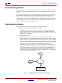
Understanding Handles . . . . . . . . . . . . . . . . . . . . . . . . . . . . . . . . . . . . . . . . . . . . . . . . . . . . 256
Data Structure Creation . . . . . . . . . . . . . . . . . . . . . . . . . . . . . . . . . . . . . . . . . . . . . . . . . . . . 256
Tcl Command Usage . . . . . . . . . . . . . . . . . . . . . . . . . . . . . . . . . . . . . . . . . . . . . . . . . . . . . . . 257
General Conventions . . . . . . . . . . . . . . . . . . . . . . . . . . . . . . . . . . . . . . . . . . . . . . . . . . . . . 257
Before You Begin . . . . . . . . . . . . . . . . . . . . . . . . . . . . . . . . . . . . . . . . . . . . . . . . . . . . . . . . 257
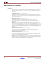
EDK Hardware Tcl Commands . . . . . . . . . . . . . . . . . . . . . . . . . . . . . . . . . . . . . . . . . . . . . 258
Overview . . . . . . . . . . . . . . . . . . . . . . . . . . . . . . . . . . . . . . . . . . . . . . . . . . . . . . . . . . . . . . .
Hardware Read Access APIs . . . . . . . . . . . . . . . . . . . . . . . . . . . . . . . . . . . . . . . . . . . . . .
API Summary . . . . . . . . . . . . . . . . . . . . . . . . . . . . . . . . . . . . . . . . . . . . . . . . . . . . . . . .
Hardware API Descriptions . . . . . . . . . . . . . . . . . . . . . . . . . . . . . . . . . . . . . . . . . . . . .
258
259
259
259
Tcl Example Procedures . . . . . . . . . . . . . . . . . . . . . . . . . . . . . . . . . . . . . . . . . . . . . . . . . . . . 266
Example 1 . . . . . . . . . . . . . . . . . . . . . . . . . . . . . . . . . . . . . . . . . . . . . . . . . . . . . . . . . . . . . .
Example 2 . . . . . . . . . . . . . . . . . . . . . . . . . . . . . . . . . . . . . . . . . . . . . . . . . . . . . . . . . . . . . .
Advanced Write Access APIs . . . . . . . . . . . . . . . . . . . . . . . . . . . . . . . . . . . . . . . . . . . . . .
Advance Write Access Hardware API Summary . . . . . . . . . . . . . . . . . . . . . . . . . . . . .
Advance Write Access Hardware API Descriptions . . . . . . . . . . . . . . . . . . . . . . . . . . .
266
267
268
268
269
Software Tcl Commands . . . . . . . . . . . . . . . . . . . . . . . . . . . . . . . . . . . . . . . . . . . . . . . . . . . 274
Software API Terminology Overview . . . . . . . . . . . . . . . . . . . . . . . . . . . . . . . . . . . . . .
Software Read Access APIs . . . . . . . . . . . . . . . . . . . . . . . . . . . . . . . . . . . . . . . . . . . . . . .
Software Read Access API Summary . . . . . . . . . . . . . . . . . . . . . . . . . . . . . . . . . . . . . .
Software Read Access API Descriptions . . . . . . . . . . . . . . . . . . . . . . . . . . . . . . . . . . . .
274
275
275
276
Tcl Flow During Hardware Platform Generation . . . . . . . . . . . . . . . . . . . . . . . . . . . . 284
Input Files . . . . . . . . . . . . . . . . . . . . . . . . . . . . . . . . . . . . . . . . . . . . . . . . . . . . . . . . . . . . . . 284
Tcl Procedures Called During Hardware Platform Generation . . . . . . . . . . . . . . . . . 284
Additional Keywords in the Merged Hardware Datastructure . . . . . . . . . . . . . . . 290
Tcl Flow During Software Platform Generation . . . . . . . . . . . . . . . . . . . . . . . . . . . . . 291
Input Files . . . . . . . . . . . . . . . . . . . . . . . . . . . . . . . . . . . . . . . . . . . . . . . . . . . . . . . . . . . . . . 291
Tcl Procedure Calls from Libgen . . . . . . . . . . . . . . . . . . . . . . . . . . . . . . . . . . . . . . . . . . . 291
Appendix D: Glossary
Terms Used in EDK . . . . . . . . . . . . . . . . . . . . . . . . . . . . . . . . . . . . . . . . . . . . . . . . . . . . . . . . 293
16
www.xilinx.com
Embedded System Tools Reference Manual
UG111, EDK 11.3.1
Chapter 1
Embedded System and Tools
Architecture Overview
This chapter describes the architecture of the embedded system tools and flows provided
in the Xilinx® Embedded Development Kit (EDK) for developing systems based on the
PowerPC®(405 and 440) processors and MicroBlaze™ embedded processors. The
following sections are included:
•
“About EDK”
•
“Additional Resources”
•
“Design Process Overview”
•
“EDK Overview”
About EDK
The Xilinx Embedded Development Kit (EDK) system tools enable you to design a
complete embedded processor system for implementation in a Xilinx FPGA device.
EDK includes:
•
The Xilinx Platform Studio (XPS) system tools suite with which you can develop your
embedded processor hardware.
•
The Software Development Kit (SDK), based on the Eclipse open-source framework,
which you can use to develop your embedded software application. SDK is also
available as a standalone program.
•
Embedded processing Intellectual Property (IP) cores including processors and
peripherals.
EDK is a component of the Integrated Software Environment (ISE®), a Xilinx development
system product that is required to implement designs into Xilinx programmable logic
devices. EDK is installed when you select it as an option during the ISE install. SDK can be
installed as a separate executable without installing ISE or EDK.
While the EDK environment supports creating and implementing designs, the
recommended flow is to begin with an ISE project, then add an embedded processor
source to the ISE project. EDK depends on ISE components to start synthesize the
microprocessor hardware design, to map that design to an FPGA target, and to generate
and download the bitstream.
For information about ISE, refer to the ISE software documentation. For links to ISE
documentation and other useful information see “Additional Resources,” page 4.
Embedded System Tools Reference Manual
UG111, EDK 11.3.1
www.xilinx.com
17
Chapter 1: Embedded System and Tools Architecture Overview
Additional Resources
•
Platform Specification Format Reference Manual
OS and Libraries Document Collection
Concepts, Tools, and Techniques
http://www.xilinx.com/ise/embedded/edk_docs.htm
•
PowerPC (405 and 440) Processor Reference Guides
http://www.xilinx.com/support/documentation/user_guides/ug018.pdf
http://www.xilinx.com/support/documentation/user_guides/ug011.pdf
•
MicroBlaze Processor User Guide
http://www.xilinx.com/support/documentation/sw_manuals/mb_ref_guide.pdf
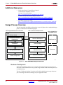
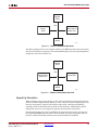
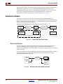
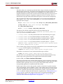
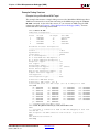
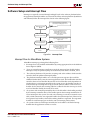
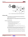
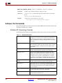
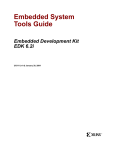
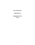
Design Process Overview
The tools provided with EDK are designed to assist in all phases of the embedded design
process, as illustrated in the following figure.
ISE Integrated Software Environment
SDK Software Development Kit
Also included in the
Embedded Edition
XPS
Xilinx Platform Studio
Processor Hardware
Development
Hardware
Platform
Software Development
Verification File
Generation
ChipScope Pro
Software Debug
Software Profiling
Design Implementation
Planahead
Device Configuration
Device Configuration
X11124
Figure 1-1:
Basic Embedded Design Process Flow
Hardware Development
Xilinx FPGA technology allows you to customize the hardware logic in your processor
subsystem. Such customization is not possible using standard off-the-shelf microprocessor
or controller chips.
The term “Hardware platform” describes the flexible, embedded processing subsystem
you are creating with Xilinx technology for your application needs.
18
www.xilinx.com
Embedded System Tools Reference Manual
UG111, EDK 11.3.1
Design Process Overview
The hardware platform consists of one or more processors and peripherals connected to
the processor buses. XPS captures the hardware platform in the Microprocessor Hardware
Specification (MHS) file.
The MHS file is the principal source file that maintains the hardware platform description
and represents in ASCII text the hardware components of your embedded system.
Software Development
A software platform is a collection of software drivers and, optionally, the operating
system on which to build your application. The created software image contains only the
portions of the Xilinx library you use in your embedded design. You can create multiple
applications to run on the software platform.
Verification
EDK provides both hardware and software verification tools. The following subsections
describe the verification tools available for hardware and software.
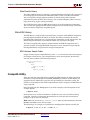
Hardware Verification Using Simulation
To verify the correct functionality of your hardware platform, you can create a simulation
model and run it on an Hardware Design Language (HDL) simulator. When simulating
your system, the processor(s) execute your software programs. You can choose to create a
behavioral, structural, or timing-accurate simulation model.
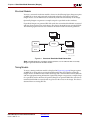
Software Verification Using Debugging
The following options are available for software verification:
•
You can load your design on a supported development board and use a debugging
tool to control the target processor.
•
You can use an Instruction Set Simulator (ISS) running on the host computer to debug
your code.
•
You can gauge the performance of your system by profiling the execution of your
code.
Device Configuration
When your hardware and software platforms are complete, you then create a
configuration bitstream for the target FPGA device.
•
For prototyping, download the bitstream along with any software you require to run
on your embedded platform while connected to your host computer.
•
For production, store your configuration bitstream and software in a non-volatile
memory connected to the FPGA.
Embedded System Tools Reference Manual
UG111, EDK 11.3.1
www.xilinx.com
19
Chapter 1: Embedded System and Tools Architecture Overview
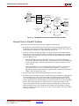
EDK Overview
An embedded hardware platform typically consists of one or more processors, peripherals
and memory blocks, interconnected via processor buses. It also has port connections to the
outside world. Each of the processor cores (also referred to as pcores or processor IPs) has a
number of parameters that you can adjust to customize its behavior. These parameters also
define the address map of your peripherals and memories. XPS lets you select from
various optional features; consequently, the FPGA needs only implement the subset of
functionality required by your application.
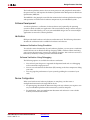
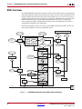
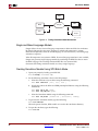
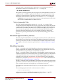
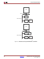
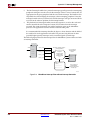
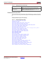
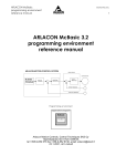
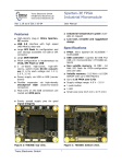
The following figure provides an overview of the EDK architecture structure of how the
tools operate together to create an embedded system.
CompXLib
Processor Software
Platform (MSS)
Processor Hardware
Platform (MHS)
IP Models
ISE Models
IP Library or User Repository
EDK Software
Libraries
(BSP, MLD...)
Library
Generator
Drivers,
MDD
MPD, PAO
.a
Libraries,
OS, MLD
PCore
HDL
Platform
Generator
System and
Wrapper HDL
Simulation
Generator
system.BMM
Behavioral
HDL Model
ISE Tools
Synthesis (XST)
Application Source
.c, .h, .s
NGC
Implementation
Constraint File
(UCF)
Compiler (GCC)
.o, .a
NGDBuild
NGD
Simulation
Generator
Structural
HDL Model
MAP, PAR
NCD
Linker Script
Linker
(GCC)
system_BD.BMM
Bitstream Generator
ELF
Bitstream Initializer
system.BIT
Simulation
Generator
Timing HDL/
SDF Model
download.BIT
Simulation
Debugger
(XMD, GDB)
download.CMD
iMPACT
JTAG Cable
FPGA
Device
X10310
Figure 1-2:
20
Embedded Development Kit (EDK) Tools Architecture
www.xilinx.com
Embedded System Tools Reference Manual
UG111, EDK 11.3.1
EDK Overview
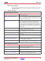
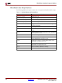
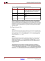
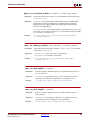
EDK Tools and Utilities
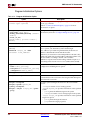
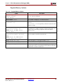
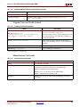
The following table describes the tools and utilities supported in EDK and the subsections
that follow provide an overview of each tool, with references to the chapters that contain
additional information.
Table 1-1:
EDK Tools and Utilities
Hardware Development and Verification
Xilinx Platform Studio (XPS)
An integrated design environment (GUI) in which you can create your
embedded hardware design.
The Base System Builder (BSB) Wizard
Allows you to quickly create a working embedded design using any
features of a supported development board or using basic functionality
common to most embedded systems. For initial project creation it is
recommended to use the BSB wizard.
The Create and Import Peripheral (CIP)
Wizard
Assists you in adding your own peripheral(s) to a design. The CIP
creates associated directories and data files required by XPS. the
Platform Specification Utility (PsfUtility) tool enables automatic
generation of Microprocessor Peripheral Definition (MPD) files,
which are required to create IP peripherals that are compliant with
the Embedded Development Kit (EDK). The CIP wizard in XPS
supports features provided by the PsfUtility for MPD file creation
(recommended.)
Coprocessor Wizard
Helps you add a coprocessor to a CPU.
(This applies to MicroBlaze-based designs only.)
Platform Generator (Platgen)
Constructs the programmable system on a chip in the form of HDL and
synthesized netlist files.
FXPS Command Line or “no window” Mode
Allows you to run embedded design flows or change tool options from
a command line.
Bus Functional Model (BFM)
Helps simplify the verification of custom peripherals by creating a
model of the bus environment to use in place of the actual embedded
system.
Simulation Model Generator (Simgen)
Generates the hardware simulation model and the compilation script
files for simulating the complete system.
Simulation Library Compiler (Compxlib)
Compiles the EDK simulation libraries for the target simulator, as
required, before starting behavioral simulation of the design.
Software Development and Verification
Software Development Kit (SDK)
An integrated design environment (GUI), that helps you with the
development of software application projects.
Library Generator (Libgen)
Constructs a software platform comprising a customized collection of
software libraries, drivers, and OS.
GNU Compiler Tools (GCC)
Builds a software application based on the platforms created by the
Libgen.
Xilinx Microprocessor Debugger (XMD)
Used for software download and debugging. Also provides a channel
through which the GNU debugger accesses the device.
Embedded System Tools Reference Manual
UG111, EDK 11.3.1
www.xilinx.com
21
Chapter 1: Embedded System and Tools Architecture Overview
Table 1-1:
EDK Tools and Utilities (Cont’d)
GNU Debugger (GDB)
GUI for debugging software on either a simulation model or target
device.
Bitstream Initializer (Bitinit)
Updates an FPGA configuration bitstream to initialize the on-chip
instruction memory with the software executable.
Debug Configuration Wizard
Automates hardware and software platform debug configuration tasks
common to most designs.
System ACE File Generator (GenACE)
Generates a Xilinx System ACE™ configuration file based on the FPGA
configuration bitstream and software executable to be stored in a
compact flash device in a production system.
Flash Memory Programmer
Allows you to use your target processor to program on-board Common
Flash Interface (CFI)-compliant parallel flash devices with software
and data.
Format Revision Tool and Version
Management Wizard
Updates the project files to the latest format. The Version Management
wizard helps migrate IPs and drivers created with an earlier EDK
release to the latest version.
Xilinx Platform Studio (XPS)
XPS provides an integrated environment for creating embedded processor systems based
on MicroBlaze and PowerPC processors. XPS also provides an editor and a project
management interface to create and edit source code. XPS offers customization of tool flow
configuration options and provides a graphical system editor for connection of processors,
peripherals, and buses. There is also a batch mode invocation of XPS available.
From XPS, you can run all embedded system tools needed to process hardware system
components. You can also perform system verification within the XPS environment.
XPS offers the following features:
•
Ability to add processor and peripheral cores, edit core parameters, and make bus
and signal connections to generate an MHS file.
•
Ability to generate and modify the MSS file.
•
Support for tools described in Table 1-1, page 21.
•
Ability to generate and view a system block diagram and/or design report.
•
Project management support.
•
Process and tool flow dependency management.
•
Ability to export hardware specification files for import into SDK.
For more information on files and their formats see the Platform Specification Format
Reference Manual which is linked in “Additional Resources,” page 18.
Refer to the Xilinx Platform Studio Help for details on using the XPS GUI. The following
subsections describe the tool and utility components of XPS.
22
www.xilinx.com
Embedded System Tools Reference Manual
UG111, EDK 11.3.1
EDK Overview
The Base System Builder (BSB) Wizard
The BSB wizard helps you quickly build a working system. Some embedded design
projects can be completed using the BSB wizard alone. For more complex projects, the BSB
wizard provides a baseline system that you can then customize to complete your
embedded design. BSB wizard can generate a single-processor design for the supported
processor types, and dual processor designs for MicroBlaze. For efficiency in project
creation, Xilinx recommends using the BSB wizard in every scenario.
Based on the board you choose, the BSB wizard allows you to select and configure basic
system elements such as processor type, debug interface, cache configuration, memory
type and size, and peripheral selection. BSB provides functional default values preselected in the wizard that can be modified as desired.
If your target development board is not available or not currently supported by the BSB
wizard, you can select the Custom Board option instead of selecting a target board. Using
this option, you can specify the individual hardware devices that you expect to have on
your custom board. To run the generated system on a custom board, you enter the FPGA
pin location constraints into the User Constraints File (UCF). If a supported target board is
selected, the BSB wizard inserts these constraints into the UCF automatically.
The BSB wizard can generate one or more optional software projects. Each project contains
a sample application and linker script that can be compiled and run on the hardware for
the target development board. Each application is designed to illustrate system aliveness
and perform simple and basic testing of some of the hardware. The contents of each test
application varies depending on the components in your system.
For detailed information on using the features provided in the BSB wizard, see the Xilinx
Platform Studio Help.
The Create and Import Peripheral (CIP) Wizard
The CIP wizard helps you create your own peripherals and import them into XPScompliant repositories or projects.
In the Create mode, the CIP wizard creates templates that help you implement your
peripheral without requiring detailed understanding of the bus protocols, naming
conventions, or the formats of special interface files required by XPS. By referring to the
examples in the template file and using various auxiliary design support files that are
output by the wizard, you can start quickly on designing your custom logic.
In the Import mode, this tool creates the interface files and directory structures that are
necessary to make your peripheral visible to the various tools in XPS.
For the Import operation mode, it is assumed that you have followed the required XPS
naming conventions. Once imported, your peripheral is available in the XPS peripherals
library.
When you create or import a peripheral, XPS generates the Microprocessor Peripheral
Definition (MPD) and Peripheral Analyze Order (PAO) files automatically:
•
The MPD file defines the interface for the peripheral.
•
The PAO file specifies to Platgen and Simgen what HDL files are required for
compilation (synthesis or simulation) for the peripheral and in the order of those files.
For more information about MPD and PAO files, see the Platform Specification Format
Reference Manual. A link to the document is available in “Additional Resources,” page 18.
For detailed information on using the features provided in the CIP wizard, see the Xilinx
Platform Studio Help.
Embedded System Tools Reference Manual
UG111, EDK 11.3.1
www.xilinx.com
23
Chapter 1: Embedded System and Tools Architecture Overview
Platform Specification Utility (PsfUtility)
The PsfUtility enables automatic generation of Microprocessor Peripheral Definition
(MPD) files required to create an IP core compliant with EDK. Features provided by this
tool can be used with the help of the CIP wizard.
For more information, see Chapter 2, “Platform Specification Utility (PsfUtility).”
Coprocessor Wizard
The Coprocessor wizard helps add and connect a coprocessor to a CPU. A coprocessor is a
hardware module that implements a user-defined function in the FPGA fabric and
connects to the processor through the Fast Simplex Link (FSL) interface. FSL channels are
dedicated point-to-point communication interfaces implemented using FIFOs. This
feature is applicable for MicroBlaze processor designs only.
or details on the Fast Simplex Link (FSL), refer to the MicroBlaze Processor Reference Guide
and the PowerPC (405 and 440) processor guides. Additionally, the Xilinx data sheet for the
FSL Bus can provide more information. Links to document locations are available in the
“Additional Resources,” page 18.
For instructions on using the Coprocessor wizard, refer to the Xilinx Platform Studio Help.
Platform Generator (Platgen)
Platform Generator (Platgen) compiles the high-level description of your embedded
processor system into HDL netlists that can be implemented in a target FPGA device.
Platgen:
•
Reads the MHS file as its primary design input.
•
Reads various processor core (pcore) hardware description files (MPD, PAO) from the
XPS project and any user IP repository.
•
Produces the top-level HDL design file for the embedded system that stitches together
all the instances of parameterized pcores contained in the system. In the process, it
resolves the high-level bus connections in the MHS into the actual signals required to
interconnect the processors, peripherals and on-chip memories. (The system-level
HDL netlist produced by Platgen is used as part of the FPGA implementation
process.)
•
Invokes the XST (Xilinx Synthesis Technology) compiler to synthesize each of the
instantiated pcores.
•
Generates the block RAM Memory Map (BMM) file which contains addresses and
configuration of on-chip block RAM memories. This file is used later for initializing
the block RAMs with software.
Chapter 3, “Platform Generator (Platgen),” provides a detailed description of the Platgen
tool.
FXPS Command Line or “no window” Mode
XPS includes a “no window” mode that allows you to run from an operating system
command line. Chapter 4, “Command Line (no window) Mode,” provides information on
the command line feature in XPS.
24
www.xilinx.com
Embedded System Tools Reference Manual
UG111, EDK 11.3.1
EDK Overview
Bus Functional Model (BFM)
Bus Functional Model simulation simplifies the verification of hardware components that
attach to a bus. For more information on bus functional models, see the BFM Simulation
document. A link to the document is available in “Additional Resources,” page 18.
Debug Configuration Wizard
The Debug Configuration wizard automates hardware and software platform debug
configuration tasks common to most designs.
You can instantiate a ChipScope™ core to monitor the Processor Local Bus (PLB) or any
other system-level signals. In addition, you can configure the parameters of an existing
ChipScope core for hardware debugging. You can also provide Joint Team Action Group
(JTAG)-based virtual input and output.
To configure the software for debugging you can set the processor debug parameters.
When co-debugging is enabled for a ChipScope core, you can set up mutual triggering
between the software debugger and the hardware signals. The JTAG interface can be
configured to transport UART signals to the Xilinx Microprocessor Debugger (XMD).
For detailed information on using the features provided in the Debug Configuration
wizard, see the Xilinx Platform Studio Help.
Simulation Model Generator (Simgen)
The Simulation Platform Generation tool (Simgen) generates and configures various
simulation models for the hardware. To generate a behavioral model, Simgen takes an
MHS file as its primary design input. For generating structural or timing models, Simgen
takes its primary design input from the post-synthesis or post-place-and-route design
database, respectively. Simgen also reads the embedded application executable (ELF) file
for each processor to initialize on-chip memory, thus allowing the modeled processor(s) to
execute their software code during simulation.
Refer to Chapter 6, “Simulation Model Generator (Simgen)” for more information.
Software Development Kit (SDK)
The SDK provides a development environment for software application projects. SDK is
based on the Eclipse open-source standard. SDK has the following features:
•
Can be installed independent of ISE and XPS with a small disk footprint.
•
Supports development of software applications on single processor or multiprocessor systems.
•
Imports the XPS-generated hardware platform definition.
•
Supports development of software applications in a team environment.
•
Supports source code revision control based on CVS.
•
Has the ability to create and configure software platforms and Board Support
Packages (BSPs) for third-party OS.
•
Provides off-the-shelf sample software projects to test the hardware and software
functionality.
•
Has an easy GUI interface to generate linker scripts for software applications,
program FPGA devices, and program parallel flash memory.
•
Has feature-rich C/C++ code editor and compilation environment.
•
Provides project management.
Embedded System Tools Reference Manual
UG111, EDK 11.3.1
www.xilinx.com
25
Chapter 1: Embedded System and Tools Architecture Overview
•
Configures application builds and automates the make file generation.
•
Supplies error navigation.
•
Provides a well-integrated environment for seamless debugging and profiling of
embedded targets.
For more information about SDK, see the Software Development ToolKit (SDK) Help.
Library Generator (Libgen)
Libgen configures libraries, device drivers, file systems, and interrupt handlers for the
embedded processor system, creating a “software platform.” The software platform
defines, for each processor, the drivers associated with the peripherals you include in your
hardware platform, selected libraries, standard input and output devices, interrupt
handler routines, and other related software features. Your SDK projects further define
software applications to run on each processor, which are based on the software platform.
Taking libraries and drivers from the installation, along with any custom libraries and
drivers for custom peripherals you provide, SDK is able to compile your applications,
including libraries and drivers, into Executable Linked Format (ELF) files that are ready to
run on your processor hardware platform.
Libgen reads selected libraries and processor core (pcore) software description files
(Microprocessor Driver Definition (MDD) and driver code) from the EDK library and any
user IP repository.
Refer to Chapter 7, “Library Generator (Libgen)” and the Xilinx Platform Studio Help for
more information. For more information on libraries and device drivers, refer to the Xilinx
software components documented in the OS and Libraries Document Collection. Links to the
documentation are supplied in the “Additional Resources,” page 18.
GNU Compiler Tools (GCC)
GNU compiler tools are called for compiling and linking application executables for each
processor in the system. Processor-specific compilers are:
•
The mb-gcc compiler for the MicroBlaze processor.
•
The powerpc-eabi-gcc compiler for the PowerPC processor.
As shown in the embedded tools architectural overview (Figure 1-2, page 20):
•
The compiler reads a set of C-code source and header files or assembler source files
for the targeted processor.
•
The linker combines the compiled applications with selected libraries and produces
the executable file in ELF format. The linker also reads a linker script, which is either
the default linker script generated by the tools or one that you have provided.
Refer to Chapter 8, “GNU Compiler Tools,”, Chapter 10, “GNU Debugger (GDB),” and
Appendix A, “GNU Utilities” for more information about GNU compiler tools and
utilities.
26
www.xilinx.com
Embedded System Tools Reference Manual
UG111, EDK 11.3.1
EDK Overview
Xilinx Microprocessor Debugger (XMD)
You can debug your program in software using an Instruction Set Simulator (ISS), or on a
board that has a Xilinx® FPGA loaded with your hardware bitstream. As shown in
Figure 1-2, page 20, the debugger utility (XMD) reads the application executable ELF file.
For debugging on a physical FPGA, XMD communicates over the same download cable as
used to configure the FPGA with a bitstream. Refer to Chapter 9, “Xilinx Microprocessor
Debugger (XMD),” for more information.
GNU Debugger (GDB)
The GNU Debugger (GDB) is a powerful yet flexible tool that provides a unified interface
for debugging and verifying MicroBlaze and PowerPC processor systems during various
development phases.
GDB uses Xilinx® Microprocessor Debugger (XMD) as the underlying engine to
communicate to processor targets.
Refer to Chapter 10, “GNU Debugger (GDB),” for more information.
Simulation Library Compiler (Compxlib)
The Compxlib utility compiles the EDK HDL-based simulation libraries using the tools
provided by various simulator vendors. The Compxlib operates in both the GUI and batch
modes. In the GUI mode, it allows you to compile the Xilinx libraries (in your ISE
installation) using the libraries available in EDK.
For more information about Compxlib, see “Simulation Models” in Chapter 6 and the ISE
Command Line Tools User Guide. For instructions on compiling simulation libraries, refer to
the Xilinx Platform Studio Help.
Bitstream Initializer (Bitinit)
The Bitinit tool initializes the on-chip block RAM memory connected to a processor with
its software information. This utility reads hardware-only bitstream produced by the ISE
tools (system.bit), and outputs a new bitstream (download.bit) which includes the
embedded application executable (ELF) for each processor. The utility uses the BMM file,
originally generated by Platgen and updated by the ISE tools with physical placement
information on each block RAM in the FPGA. Internally, the Bitstream Initializer tool uses
the Data2MEM utility to update the bitstream file.
See Figure 1-2, page 20, to see how the Bitinit tool fits into the overall system architecture.
Refer to Chapter 11, “Bitstream Initializer (BitInit),” for more information.
System ACE File Generator (GenACE)
XPS generates Xilinx System ACE configuration files from an FPGA bitstream, ELF, and
data files. The generated ACE file can be used to configure the FPGA, initialize block RAM,
initialize external memory with valid program or data, and bootup the processor in a
production system. EDK provides a Tool Command Language (Tcl) script, genace.tcl,
that uses XMD commands to generate ACE files. ACE files can be generated for PowerPC
processors and MicroBlaze processors with Microprocessor Debug Module (MDM)
systems.
For more information see Chapter 12, “System ACE File Generator (GenACE).”
Embedded System Tools Reference Manual
UG111, EDK 11.3.1
www.xilinx.com
27
Chapter 1: Embedded System and Tools Architecture Overview
Flash Memory Programmer
The Flash Memory Programming solution is designed to be generic and targets a wide
variety of flash hardware and layouts. See Chapter 13, “Flash Memory Programming.”
Format Revision Tool and Version Management Wizard
The Format Revision Tool (revup) updates an existing EDK project to the current version.
The revup tool performs format changes only; it does not update your design.
Backups of existing files such as the project file (XMP), the MHS and MSS files, are
performed before the format changes are applied.
The Version Management wizard appears automatically when an older project is opened
in a newer version of EDK (for example, when a project created in EDK 10.1 is opened in
version 11.3).
The Version Management wizard is invoked after format revision has been performed. The
wizard provides information about any changes in Xilinx Processor IPs used in the design.
If a new compatible version of an IP is available, then the wizard also prompts you to
update to the new version. For instructions on using the Version Management wizard, see
Chapter 14, “Version Management Tools (revup),” and the Xilinx Platform Studio Help.
Xilinx Bash Shell
Because GNU-based tools on the NT platform require a LINUX emulation shell, the Red
Hat Cygwin™ shell and utilities are provided as part of the EDK installation. Refer to
Chapter 15, “Xilinx Bash Shell,” for more information about Cygwin and the requirements
to comply with the EDK tool suite.
28
www.xilinx.com
Embedded System Tools Reference Manual
UG111, EDK 11.3.1
R
Chapter 2
Platform Specification Utility
(PsfUtility)
This chapter describes the various features and the usage of the Platform Specification
Utility (PsfUtility) tool that enables automatic generation of Microprocessor Peripheral
Definition (MPD) files. MPD files are required to create IP peripherals that are compliant
with the Embedded Development Kit (EDK). The Create and Import Peripheral (CIP)
wizard in the Xilinx® Platform Studio (XPS) interface supports features provided by the
PsfUtility for MPD file creation (recommended).
This chapter contains the following sections:
•
“Tool Options”
•
“MPD Creation Process Overview”
•
“Use Models for Automatic MPD Creation”
•
“DRC Checks in PsfUtility”
•
“Conventions for Defining HDL Peripherals”
Embedded System Tools Reference Manual
UG111, EDK 11.3.1
www.xilinx.com
29
R
Tool Options
Tool Options
Table 2-1:
PsfUtility Syntax Options
Option
Single IP MHS
template
Command
-deploy_core
<corename>
<coreversion>
Description
Generate MHS Template that instantiates a single peripheral.
Suboptions are:
-lp <Library_Path>— Add one or more additional IP library
search paths
-o <outfile>— Specify output filename; default is stdout
Help
-h, -help
Displays the usage menu then exits.
HDL file to MPD
-hdl2mpd <hdlfile>
Generate MPD from the VHDL/Ver/src/prj file.
Suboptions are:
-lang {ver|vhdl} — Specify language
-top <design> — Specify top-level entity or module name
-bus {opb(2)|plb(2)|plbv46|dcr|lmb|fsl m|s|ms|mb(1)
[<busif_name>]}— Specify one or more bus interfaces for the
peripheral
-p2pbus <busif_name> <bus_std>
{target|initiator} — Specify one or more point-to-point
connections for the peripheral
-o <outfile> — Specify output filename; default is stdout
PAO file to MPD
-pao2mpd <paofile>
Generate MPD from Peripheral Analyze Order (PAO) file.
Suboptions are:
-lang {ver|vhdl} — Specify language
-top <design> — Specify top-level entity or module name
-bus {opb(2)|plb(2)|plbv46|dcr|lmb|fsl m|s|ms|mb(1)
[<busif_name>]}— Specify one or more peripherals and
optional interface name(s)
-p2pbus <busif_name> <bus_std>
{target|initiator} — Specify one or more point-to-point
connections of the peripheral
-o <outfile> — Specify output filename; default is stdout
Display version
information
-v
Displays the version number
Note:
1. Bus type mb (master that generates burst transactions) is valid for bus standard PLBv46 only.
2. Deprecated in this release.
30
www.xilinx.com
Embedded System Tools Reference Manual
UG111, EDK 11.3.1
R
Chapter 2: Platform Specification Utility (PsfUtility)
MPD Creation Process Overview
You can use the PsfUtility to create MPD specifications from the HDL specification of the
core automatically. To create a peripheral and deliver it through EDK:
1.
Code the IP in VHDL or Verilog using the required naming conventions for Bus, Clock,
Reset, and Interrupt signals. These naming conventions are described in detail in
“Conventions for Defining HDL Peripherals” on page 34.
Note: Following these naming conventions enables the PsfUtility to create a correct and
complete MPD file.
2.
Create an XST (Xilinx Synthesis Technology) project file or a PAO file that lists the HDL
sources required to implement the IP.
3.
Invoke the PsfUtility by providing the XST project file or the PAO file with additional
options.
For more information on invoking the PsfUtility with different options, see the following
section, “Use Models for Automatic MPD Creation.”
Use Models for Automatic MPD Creation
You can run the PsfUtility in a variety of ways, depending on the bus standard and bus
interface types used with the peripheral and the number of bus interfaces a peripheral
contains. Bus standards and types can be one of the following:
•
OPB (1) (on-chip peripheral bus) SLAVE
•
OPB(1) MASTER
•
OPB(1) MASTER_SLAVE
•
PLB(1) (processor local bus) SLAVE
•
PLB(1)MASTER
•
PLB(1) MASTER_SLAVE
•
PLBV46 (processor local bus version 4.6) SLAVE
•
PLBV46 MASTER
•
DCR (design control register) SLAVE
•
LMB (local memory bus) SLAVE
•
FSL (fast simplex link) SLAVE
•
FSL MASTER
•
POINT TO POINT BUS (special case)
1. Deprecated in this release.
Embedded System Tools Reference Manual
UG111, EDK 11.3.1
www.xilinx.com
31
R
Use Models for Automatic MPD Creation
Peripherals with a Single Bus Interface
Most processor peripherals have a single bus interface. This is the simplest model for the
PsfUtility. For most such peripherals, complete MPD specifications can be obtained
without any additional attributes added to the source code.
Signal Naming Conventions
The signal names must follow the conventions specified in “Conventions for Defining
HDL Peripherals” on page 34. When there is only one bus interface, no bus identifier need
be specified for the bus signals.
Invoking the PsfUtility
The command line for invoking PsfUtility is as follows:
psfutil -hdl2mpd <hdlfile> -lang {vhdl|ver} -top <top_entity>
-bus <busstd> <bustype> -o <mpdfile>
For example, to create an MPD specification for an PLB slave peripheral such as UART, the
command is:
psfutil -hdl2mpd uart.prj -lang vhdl -top uart -bus plb s -o uart.mpd
Peripherals with Multiple Bus Interfaces
Some peripherals might have multiple associated bus interfaces. These interfaces can be
exclusive bus interfaces, non-exclusive bus interfaces, or a combination of both. All bus
interfaces on the peripheral that can be connected to the peripheral simultaneously are
exclusive interfaces. For example, an OPB Slave bus interface and a DCR Slave bus
interface are exclusive because they can be connected simultaneously.
Note: On a peripheral containing exclusive bus interfaces: a port can be connected to only one of
the exclusive bus interfaces.
Non-exclusive bus interfaces cannot be connected simultaneously.
Note: Peripherals with non-exclusive bus interfaces have ports that can be connected to more than
one of the non-exclusive interfaces. Further, non-exclusive interfaces have the same bus interface
standard.
Non-Exclusive and Exclusive Bus Interfaces
Signal Naming Conventions
Signal names must adhere to the conventions specified in “Conventions for Defining HDL
Peripherals” on page 34.
•
For non-exclusive bus interfaces, bus identifiers need not be specified.
•
For exclusive bus interfaces, identifiers must be specified only when the peripheral
has more than one bus interface of the same bus standard and type.
Invoking the PsfUtility With Buses Specified in the Command Line
You can specify buses on the command line when the bus signals do not have bus identifier
prefixes. The command line for invoking the PsfUtility is as follows:
psfutil -hdl2mpd <hdlfile> -lang {vhdl|ver} -top <top_entity>
[-bus <busstd> <bustype>] -o <mpdfile>
32
www.xilinx.com
Embedded System Tools Reference Manual
UG111, EDK 11.3.1
R
Chapter 2: Platform Specification Utility (PsfUtility)
Exclusive and Non-exclusive Bus Interface Command Line Examples
For an example of a non-exclusive bus interface, to create an MPD specification for a
peripheral with a PLB slave interface and a PLB Master/Slave interface such as gemac, the
command is:
psfutil -hdl2mpd gemac.prj -lang vhdl -top gemac -bus plb s -bus plb ms
-o gemac.mpd
For an example of an exclusive bus identifier, to create an MPD specification for a
peripheral with a PLB slave interface and a DCR Slave interface, the command is:
psfutil -hdl2mpd mem.prj -lang vhdl -top mem -bus plb s -bus dcr s -o
mem.prj
Peripherals with Point-to-Point Connections
Some peripherals, such as multi-channel memory controllers, might have point-to-point
connections (BUS_STD = XIL_MEMORY_CHANNEL, BUS_TYPE = TARGET).
Signal Naming Conventions
The signal names must follow conventions such that all signals belonging to the point-topoint connection start with the same bus interface name prefix, such as MCH0_*.
Invoking the PsfUtility with Point-to-Point Connections Specified in the Command
Line
You can specify point-to-point connections in the command line using the bus interface
name as a prefix to the bus signals. The command line for invoking PsfUtil is:
psfutil -hdl2mpd <hdlfile> -lang {vhdl|ver} -top <top_entity>
-p2pbus <busif_name> <bus_std> {target|initiator} -o <mpdfile>
For example, to create an MPD specification for a peripheral with an MCH0 connection, the
command is:
psfutil -hdl2mpd mch_mem.prj -lang vhdl -top mch_mem -p2pbus MCH0
XIL_MEMORY_CHANNEL TARGET -o mch_mem.mpd
Embedded System Tools Reference Manual
UG111, EDK 11.3.1
www.xilinx.com
33
R
DRC Checks in PsfUtility
DRC Checks in PsfUtility
To enable generation of correct and complete MPD files from HDL sources, the PsfUtility
reports DRC errors. The DRC checks are listed in the following subsections in the order
they are performed.
HDL Source Errors
The PsfUtility returns a failure status if errors are found in the HDL source files.
Bus Interface Checks
Depending on what bus interface is associated with which cores, the PsfUtility does the
following for every specified bus interface:
•
Checks and reports any missing bus signals
•
Checks and reports any repeated bus signals
The PsfUtility generates an MPD file when all bus interface checks are completed.
Conventions for Defining HDL Peripherals
The top-level HDL source file for an IP peripheral defines the interface for the design and
has the following characteristics:
•
Lists ports and default connectivity for bus interfaces
•
Lists parameters (generics) and default values
•
Parameters defined in the MHS overwrite corresponding HDL source parameters
Individual peripheral documentation contains information on source file options.
34
www.xilinx.com
Embedded System Tools Reference Manual
UG111, EDK 11.3.1
R
Chapter 2: Platform Specification Utility (PsfUtility)
Naming Conventions for Bus Interfaces
A bus interface is a grouping of related interface signals. For the automation tools to
function properly, you must adhere to the signal naming conventions and parameters
associated with a bus interface. When the signal naming conventions are correctly
specified, the following interface types are recognized automatically, and the MPD file
contains the bus interface label shown in the following table.
Table 2-2:
Recognized Bus Interfaces
Description
Bus Label in MPD
Slave DCR interface
SDCR
Slave LMB interface
SLMB
Master OPB (a) interface
MOPB
Master/Slave OPB(a) interface
MSOPB
Slave OPB (a) interface
SOPB
Master PLB (a) interface
MPLB
Master/Slave PLB(a) interface
MSPLB
Slave PLB(a) interface
SPLB
Master PLBV46 interface
MPLB
Slave PLBV46 interface
SPLB
Master FSL interface
MFSL
Slave FSL interface
SFSL
a. Deprecated in this release.
For components that have more than one bus interface of the same type, naming
conventions must be followed so the automation tools can group the bus interfaces.
Embedded System Tools Reference Manual
UG111, EDK 11.3.1
www.xilinx.com
35
R
Conventions for Defining HDL Peripherals
Naming Conventions for VHDL Generics
For peripherals that contain more than one of the same bus interface, a bus identifier must
be used. The bus identifier must be attached to all associated signals and generics.
Generic names must be VHDL-compliant. Additional conventions for IP peripherals are:
•
The generic must start with C_.
•
If more than one instance of a particular bus interface type is used on a peripheral, a
bus identifier <BI> must be used in the signal.
•
If a bus identifier is used for the signals associated with a port, the generics associated
with that port can optionally use <BI>.
•
If no <BI> string is used in the name, the generics associated with bus parameters are
assumed to be global. For example, C_DOPB_DWIDTH has a bus identifier of D and is
associated with the bus signals that also have a bus identifier of D. If only
C_OPB_DWIDTH is present, it is associated with all OPB buses regardless of the bus
identifier on the port signals.
Note: For the PLBV46 bus interface, the bus identifier <BI> is treated as the bus tag (bus interface
name). For example, C_SPLB0_DWIDTH has a bus identifier (tag) SPLB0 and is associated with the
bus signals that also have a bus identifier of SPLB0 as the prefix.
•
For peripherals that have only a single bus interface (which is the case for most
peripherals), the use of the bus identifier string in the signal and generic names is
optional, and the bus identifier is typically not included.
•
All generics that specify a base address must end with _BASEADDR, and all generics
that specify a high address must end with _HIGHADDR. Further, to tie these addresses
with buses, they must also follow the conventions for parameters, as listed above.
•
For peripherals with more than one bus interface type, the parameters must have the
bus standard type specified in the name. For example, parameters for an address on
the PLB bus must be specified as C_PLB_BASEADDR and C_PLB_HIGHADDR.
The Platform Generator (Platgen) expands and populates certain reserved generics
automatically. For correct operation, a bus tag must be associated with these parameters.
To have the PsfUtility infer this information automatically, all specified conventions must
be followed for reserved generics as well. This can help prevent errors when your
peripheral requires information on the platform that is generated. Table 2-3, page 37 lists
the reserved generic names.
36
www.xilinx.com
Embedded System Tools Reference Manual
UG111, EDK 11.3.1
R
Chapter 2: Platform Specification Utility (PsfUtility)
Table 2-3:
Automatically Expanded Reserved Generics
Parameter
Description
C_FAMILY
FPGA device family
C_INSTANCE
Instance name of component
C_<BI>OPB_NUM_MASTERS
Number of OPB masters
C_<BI>OPB_NUM_SLAVES
Number of OPB slaves
C_<BI>DCR_AWIDTH
DCR address width
C_<BI>DCR_DWIDTH
DCR data width
C_<BI>DCR_NUM_SLAVES
Number of DCR slaves
C_<BI>FSL_DWIDTH
FSL data width
C_<BI>LMB_AWIDTH
LMB address width
C_<BI>LMB_DWIDTH
LMB data width
C_<BI>LMB_NUM_SLAVES
Number of LMB slaves
C_<BI>OPB_AWIDTH
OPB address width
C_<BI>OPB_DWIDTH
OPB data width
C_<BI>PLB_AWIDTH
PLB address width
C_<BI>PLB_DWIDTH
PLB data width
C_<BI>PLB_MID_WIDTH
PLB master ID width
C_<BI>PLB_NUM_MASTERS
Number of PLB masters
C_<BI>PLB_NUM_SLAVES
Number of PLB slaves
Embedded System Tools Reference Manual
UG111, EDK 11.3.1
www.xilinx.com
37
R
Conventions for Defining HDL Peripherals
Reserved Parameters
The following table lists the parameters that Platgen populates automatically.
Table 2-4:
Reserved Parameters
Parameter
Description
C_BUS_CONFIG
Defines the bus configuration of the MicroBlaze processor.
C_FAMILY
Defines the FPGA device family.
C_INSTANCE
Defines the instance name of the component.
C_DCR_AWIDTH
Defines the DCR address width.
C_DCR_DWIDTH
Defines the DCR data width.
C_DCR_NUM_SLAVES
Defines the number of DCR slaves on the bus.
C_LMB_AWIDTH
Defines the LMB address width.
C_LMB_DWIDTH
Defines the LMB data width.
C_LMB_NUM_SLAVES
Defines the number of LMB slaves on the bus.
C_OPB_AWIDTH
Defines the OPB address width.
C_OPB_DWIDTH
Defines the OPB data width.
C_OPB_NUM_MASTERS
Defines the number of OPB(a) masters on the bus.
C_OPB_NUM_SLAVES
Defines the number of OPB(a) slaves on the bus.
C_PLB_AWIDTH
Defines the PLB(a) address width.
C_PLB_DWIDTH
Defines the PLB(a) data width.
C_PLB_MID_WIDTH
Defines the PLB(a) master ID width. This is set to log2(S).
C_PLB_NUM_MASTERS
Defines the number of PLB(a) masters on the bus.
C_PLB_NUM_SLAVES
Defines the number of PLB(a) slaves on the bus.
a. Deprecated in this release.
38
www.xilinx.com
Embedded System Tools Reference Manual
UG111, EDK 11.3.1
Chapter 2: Platform Specification Utility (PsfUtility)
R
Naming Conventions for Bus Interface Signals
This section provides naming conventions for bus interface signal names. The conventions
are flexible to accommodate embedded processor systems that have more than one bus
interface and more than one bus interface port per component. When peripherals with
more than one bus interface port are included in a design, it is important to understand
how to use a bus identifier. (As explained previously, a bus identifier must be used for
peripherals that contain more than one of the same bus interface. The bus identifier must
be attached to all associated signals and generics.)
The names must be HDL compliant. Additional conventions for IP peripherals are:
•
The first character in the name must be alphabetic and uppercase.
•
The fixed part of the identifier for each signal must appear exactly as shown in the
applicable section below. Each section describes the required signal set for one bus
interface type.
•
If more than one instance of a particular bus interface type is used on a peripheral, the
bus identifier <BI> must be included in the signal identifier. The bus identifier can be
as simple as a single letter or as complex as a descriptive string with a trailing
underscore (_) peripheral. <BI> must be included in the port signal identifiers in the
following cases:
-
The peripheral has more than one slave PLB (1) port
-
The peripheral has more than one master PLB(1) port
-
The peripheral has more than one slave LMB port
-
The peripheral has more than one slave DCR port
-
The peripheral has more than one master DCR port
-
The peripheral has more than one slave FSL port
-
The peripheral has more than one master FSL port
-
The peripheral has more than one slave PLBV46 port
-
The peripheral has more than one master PLBV46 port
-
The peripheral has more than one OPB(1) port of any type (master, slave, or
master/slave)
-
The peripheral has more than one port of any type and the choice of <Mn> or
<Sln> causes ambiguity in the signal names. For example, a peripheral with both
a master OPB(1) port and master PLB(1) port and the same <Mn> string for both
ports requires a <BI> string to differentiate the ports because the address bus
signal would be ambiguous without <BI>
For peripherals that have only a single bus interface (which is the case for most
peripherals), the use of the bus identifier string in the signal names is optional, and the bus
identifier is typically not included.
1. Deprecated in this release.
Embedded System Tools Reference Manual
UG111, EDK 11.3.1
www.xilinx.com
39
R
Conventions for Defining HDL Peripherals
Global Ports
The names for the global ports of a peripheral, such as clock and reset signals, are
standardized. You can use any name for other global ports, such as the interrupt signal.
LMB - Clock and Reset
LMB_Clk
LMB_Rst
OPB (1) - Clock and Reset
OPB_Clk
OPB_Rst
PLB(1) - Clock and Reset
PLB_Clk
PLB_Rst
PLBV46 Slave - Clock and Reset
SPLB_Clk
SPLB_Rst
PLBV46 Master - Clock and Reset
MPLB_Clk
MPLB_Rst
Slave DCR Ports
Slave DCR ports must follow the naming conventions shown in the following table:
Table 2-5:
Slave DCR Port Naming Conventions
<Sln>
A meaningful name or acronym for the slave output. <Sln> must not contain
the string DCR (upper, lower, or mixed case), so that slave outputs are not
confused with bus outputs.
<nDCR>
A meaningful name or acronym for the slave input. The last three characters
of <nDCR> must contain the string DCR (upper, lower, or mixed case).
<BI>
A bus identifier. Optional for peripherals with a single slave DCR port, and
required for peripherals with multiple slave DCR ports. <BI> must not
contain the string DCR (upper, lower, or mixed case). For peripherals with
multiple slave DCR ports, the <BI> strings must be unique for each bus
interface.
Note: If <BI> is present, <Sln> is optional.
1. Deprecated in this release.
40
www.xilinx.com
Embedded System Tools Reference Manual
UG111, EDK 11.3.1
R
Chapter 2: Platform Specification Utility (PsfUtility)
DCR Slave Outputs
For interconnection to the DCR, all slaves must provide the following outputs:
<BI><Sln>_dcrDBus : out std_logic_vector(0 to C_<BI>DCR_DWIDTH-1);
<BI><Sln>_dcrAck : out std_logic;
Examples:
Uart_dcrAck
: out std_logic;
Intc_dcrAck
: out std_logic;
Memcon_dcrAck : out std_logic;
Bus1_timer_dcrAck : out std_logic;
Bus1_timer_dcrDBus : out std_logic_vector(0 to C_<BI>DCR_DWIDTH-1);
Bus2_timer_dcrAck : out std_logic;
Bus2_timer_dcrDBus : out std_logic_vector(0 to C_<BI>DCR_DWIDTH-1);
DCR Slave Inputs
For interconnection to the DCR, all slaves must provide the following inputs:
<BI><nDCR>_ABus
<BI><nDCR>_DBus
<BI><nDCR>_Read
<BI><nDCR>_Write
:
:
:
:
in
in
in
in
std_logic_vector(0 to C_<BI>DCR_AWIDTH-1);
std_logic_vector(0 to C_<BI>DCR_DWIDTH-1);
std_logic;
std_logic;
Examples:
DCR_DBus
: in
Bus1_DCR_DBus : in
std_logic_vector(0 to C_<BI>DCR_DWIDTH-1);
std_logic_vector(0 to C_<BI>DCR_DWIDTH-1);
Slave FSL Ports
The following table contains the required Slave FSL port naming conventions:
Table 2-6:
Slave FSL Port Naming Conventions
<nFSL> or
<nFSL_S>
A meaningful name or acronym for the slave I/O. The last five characters of
<nFSL_S> must contain the string FSL_S (upper, lower, or mixed case).
<BI>
A bus identifier. Optional for peripherals with a single slave FSL port and
required for peripherals with multiple slave FSL ports. <BI> must not contain
the string FSL_S (upper, lower, or mixed case). For peripherals with multiple
slave FSL ports, the <BI> strings must be unique for each bus interface.
FSL Slave Outputs
For interconnection to the FSL, slaves must provide the following outputs:
<BI><nFSL_S>_Data
: out std_logic_vector(0 to C_<BI>FSL_DWIDTH-1);
<BI><nFSL_S>_Control : out std_logic;
<BI><nFSL_S>_Exists : out std_logic;
Examples:
FSL_S_Control
: out std_logic;
Memcon_FSL_S_Control : out std_logic;
Bus1_timer_FSL_S_Control: out std_logic;
Bus1_timer_FSL_S_Data: out std_logic_vector(0 to C_<BI>FSL_DWIDTH-1);
Bus2_timer_FSL_S_Control: out std_logic;
Bus2_timer_FSL_S_Data: out std_logic_vector(0 to C_<BI>FSL_DWIDTH-1);
Embedded System Tools Reference Manual
UG111, EDK 11.3.1
www.xilinx.com
41
R
Conventions for Defining HDL Peripherals
FSL Slave Inputs
For interconnection to the FSL, slaves must provide the following inputs:
<BI><nFSL>_Clk
<BI><nFSL>_Rst
<BI><nFSL_S>_Clk
<BI><nFSL_S>_Read
:
:
:
:
in
in
in
in
std_logic;
std_logic;
std_logic;
std_logic;
Examples:
FSL_S_Read : in std_logic;
Bus1_FSL_S_Read : in std_logic;
Master FSL Ports
The following table lists the required Master FSL ports naming conventions:
Table 2-7:
Master FSL Port Naming Conventions
<nFSL> or
<nFSL_M>
A meaningful name or acronym for the master I/O. The last five characters of
<nFSL_M> must contain the string FSL_M (upper, lower, or mixed case).
<BI>
A bus identifier. Optional for peripherals with a single master FSL port, and
required for peripherals with multiple master FSL ports. <BI> must not
contain the string FSL_M (upper, lower, or mixed case). For peripherals with
multiple master FSL ports, the <BI> strings must be unique for each bus
interface.
FSL Master Outputs
For interconnection to the FSL, masters must provide the following outputs:
<BI><nFSL_M>_Full: out std_logic;
Examples:
FSL_M_Full
:out std_logic;
Memcon_FSL_M_Full: out std_logic;
FSL Master Inputs
For interconnection to the FSL, masters must provide the following inputs:
<BI><nFSL>_Clk
: in
<BI><nFSL>_Rst
: in
<BI><nFSL_M>_Clk
: in
<BI><nFSL_M>_Data : in
<BI><nFSL_M>_Control: in
<BI><nFSL_M>_Write : in
std_logic;
std_logic;
std_logic;
std_logic_vector(0 to C_<BI>FSL_DWIDTH-1);
std_logic;
std_logic;
Examples:
FSL_M_Write
: in std_logic;
Bus1_FSL_M_Write
: in std_logic;
Bus1_timer_FSL_M_Control: out std_logic;
Bus1_timer_FSL_M_Data: out std_logic_vector(0 to C_<BI>FSL_DWIDTH-1);
Bus2_timer_FSL_M_Control: out std_logic;
Bus2_timer_FSL_M_Data: out std_logic_vector(0 to C_<BI>FSL_DWIDTH-1);
42
www.xilinx.com
Embedded System Tools Reference Manual
UG111, EDK 11.3.1
R
Chapter 2: Platform Specification Utility (PsfUtility)
Slave LMB Ports
Slave LMB ports must follow the naming conventions shown in the table below:
Table 2-8:
Slave LMB Port Naming Conventions
<Sln>
A meaningful name or acronym for the slave output. <Sln> must not contain
the string LMB (upper, lower, or mixed case), so that slave outputs will not be
confused with bus outputs.
<nLMB>
A meaningful name or acronym for the slave input. The last three characters
of <nLMB> must contain the string LMB (upper, lower, or mixed case).
<BI>
Optional for peripherals with a single slave LMB port and required for
peripherals with multiple slave LMB ports. <BI> must not contain the string
LMB (upper, lower, or mixed case). For peripherals with multiple slave LMB
ports, the <BI> strings must be unique for each bus interface.
Note: If <BI> is present, <Sln> is optional.
LMB Slave Outputs
For interconnection to the LMB, slaves must provide the following outputs:
<BI><Sln>_DBus : out std_logic_vector(0 to C_<BI>LMB_DWIDTH-1);
<BI><Sln>_Ready : out std_logic;
Examples:
D_Ready : out std_logic;
I_Ready : out std_logic;
LMB Slave Inputs
For interconnection to the LMB, slaves must provide the following inputs:
<BI><nLMB>_ABus
: in std_logic_vector(0 to C_<BI>LMB_AWIDTH-1);
<BI><nLMB>_AddrStrobe: in std_logic;
<BI><nLMB>_BE
: in std_logic_vector(0 to C_<BI>LMB_DWIDTH/8-1);
<BI><nLMB>_Clk
: in std_logic;
<BI><nLMB>_ReadStrobe: in std_logic;
<BI><nLMB>_Rst
: in std_logic;
<BI><nLMB>_WriteDBus : in std_logic_vector(0 to C_<BI>LMB_DWIDTH-1);
<BI><nLMB>_WriteStrobe: in std_logic;
Examples:
LMB_ABus : in
DLMB_ABus : in
Embedded System Tools Reference Manual
UG111, EDK 11.3.1
std_logic_vector(0 to C_LMB_AWIDTH-1);
std_logic_vector(0 to C_DLMB_AWIDTH-1);
www.xilinx.com
43
R
Conventions for Defining HDL Peripherals
Master OPB (1) Ports
The signal list in the following table applies to master OPB ports that are independent of
slave OPB ports. Master OPB ports must follow the naming conventions shown in the
following table:
Table 2-9:
Master OPB Port Naming Conventions
<Mn>
A meaningful name or acronym for the master output. <Mn> must not contain the
string OPB (upper, lower, or mixed case), so that master outputs will not be
confused with bus outputs.
<nOPB>
A meaningful name or acronym for the master input. The last three characters of
<nOPB> must contain the string OPB (upper, lower, or mixed case).
<BI>
A bus identifier. Optional for peripherals with a single OPB port (of any type),
and required for peripherals with multiple OPB ports (of any type or mix of
types). <BI> must not contain the string OPB (upper, lower, or mixed case). For
peripherals with multiple OPB ports, the <BI> strings must be unique for each
bus interface.
Note: If <BI> is present, <Mn> is optional.
OPB Master Outputs
For interconnection to the OPB, masters must provide the following outputs:
<BI><Mn>_ABus
<BI><Mn>_BE
<BI><Mn>_busLock
<BI><Mn>_DBus
<BI><Mn>_request
<BI><Mn>_RNW
<BI><Mn>_select
<BI><Mn>_seqAddr
:
:
:
:
:
:
:
:
out
out
out
out
out
out
out
out
std_logic_vector(0 to C_<BI>OPB_AWIDTH-1);
std_logic_vector(0 to C_<BI>OPB_DWIDTH/8-1);
std_logic;
std_logic_vector(0 to C_<BI>OPB_DWIDTH-1);
std_logic;
std_logic;
std_logic;
std_logic;
Examples:
IM_request
: out std_logic;
Bridge_request : out std_logic;
O2Ob_request
: out std_logic;
OPB Master Inputs
For interconnection to the OPB, all masters must provide the following inputs:
<BI><nOPB>_Clk
<BI><nOPB>_DBus
<BI><nOPB>_errAck
<BI><nOPB>_MGrant
<BI><nOPB>_retry
<BI><nOPB>_Rst
<BI><nOPB>_timeout
<BI><nOPB>_xferAck
:
:
:
:
:
:
:
:
in
in
in
in
in
in
in
in
std_logic;
std_logic_vector(0 to C_<BI>OPB_DWIDTH-1);
std_logic;
std_logic;
std_logic;
std_logic;
std_logic;
std_logic;
Examples:
IOPB_DBus
: in
std_logic_vector(0 to C_IOPB_DWIDTH-1);
1. Deprecated in this release.
44
www.xilinx.com
Embedded System Tools Reference Manual
UG111, EDK 11.3.1
R
Chapter 2: Platform Specification Utility (PsfUtility)
OPB_DBus
: in
Bus1_OPB_DBus : in
std_logic_vector(0 to C_OPB_DWIDTH-1);
std_logic_vector(0 to C_Bus1_OPB_DWIDTH-1);
Slave OPB (1) Ports
The signal list shown below applies to slave OPB ports that are independent of master OPB
ports. For the signal list for peripherals that use a combined master and slave bus interface,
refer to “Master/Slave OPB Ports” on page 46.
Slave OPB ports must follow the naming conventions shown in the table below:
Table 2-10:
Slave OPB Port Naming Conventions
<Sln>
A meaningful name or acronym for the slave output. <Sln> must not contain
the string OPB (upper, lower, or mixed case), to ensure that slave outputs are
not confused with bus outputs.
<nOPB>
A meaningful name or acronym for the slave input. The last three characters
of <nOPB> must contain the string OPB (upper, lower, or mixed case).
<BI>
A Bus Identifier. Optional for peripherals with a single OPB port, and required
for peripherals with multiple OPB ports (of any type). <BI> must not contain
the string OPB (upper, lower, or mixed case). For peripherals with multiple
OPB ports (of any type or mix of types), the <BI> strings must be unique for
each bus interface.
Note: If <BI> is present, <Sln> is optional.
OPB Slave Outputs
For interconnection to the OPB, all slaves must provide the following outputs:
<BI><Sln>_DBus
<BI><Sln>_errAck
<BI><Sln>_retry
<BI><Sln>_toutSup
<BI><Sln>_xferAck
:
:
:
:
:
out
out
out
out
out
std_logic_vector(0 to C_<BI>OPB_DWIDTH-1);
std_logic;
std_logic;
std_logic;
std_logic;
Examples:
Tmr_xferAck
Uart_xferAck
Intc_xferAck
: out std_logic;
: out std_logic;
: out std_logic;
OPB Slave Inputs
For interconnection to the OPB, all slaves must provide the following inputs:
<BI><nOPB>_ABus
<BI><nOPB>_BE
<BI><nOPB>_Clk
<BI><nOPB>_DBus
<BI><nOPB>_Rst
<BI><nOPB>_RNW
<BI><nOPB>_select
<BI><nOPB>_seqAddr
:
:
:
:
:
:
:
:
in
in
in
in
in
in
in
in
std_logic_vector(0 to C_<BI>OPB_AWIDTH-1);
std_logic_vector(0 to C_<BI>OPB_DWIDTH/8-1);
std_logic;
std_logic_vector(0 to C_<BI>OPB_DWIDTH-1);
std_logic;
std_logic;
std_logic;
std_logic;
1. Deprecated in this release.
Embedded System Tools Reference Manual
UG111, EDK 11.3.1
www.xilinx.com
45
R
Conventions for Defining HDL Peripherals
Examples:
OPB_DBus
IOPB_DBus
Bus1_OPB_DBus
: in
: in
: in
std_logic_vector(0 to C_OPB_DWIDTH-1);
std_logic_vector(0 to C_IOPB_DWIDTH-1);
std_logic_vector(0 to C_Bus1_OPB_DWIDTH-1);
Master/Slave OPB (1) Ports
The following table shows the signal list that applies to master and slave type OPB ports
that attach to the same OPB bus and share the input and output data buses. This bus
interface type is typically used when a peripheral has both master and slave functionality
and when DMA is included with the peripheral. It is useful for the master and slave to
share the input and output data buses. Master and slave OPB ports must follow these
naming conventions.
Table 2-11:
Master/Slave OPB Port Naming Conventions
<Mn>
A meaningful name or acronym for the master output. <Mn> must not contain
the string OPB (upper, lower, or mixed case), so that master outputs are not
confused with bus outputs.
<Sln>
A meaningful name or acronym for the slave output. To avoid confusion
between slave and bus outputs, <Sln> must not contain the string OPB (upper,
lower, or mixed case).
<nOPB>
A meaningful name or acronym for the slave input. The last three characters
of <nOPB> must contain the string OPB (upper, lower, or mixed case).
<BI>
A bus identifier. Optional for peripherals with a single OPB port and required
for peripherals with multiple OPB ports (of any type). <BI> must not contain
the string OPB (upper, lower, or mixed case). For peripherals with multiple
OPB ports (of any type or mix of types), the <BI> strings must be unique for
each bus interface.
Note: If <BI> is present, <Sln> and <Mn> are optional.
OPB Master/Slave Outputs
For interconnection to the OPB, all master and slaves must provide the following outputs:
<BI><Sln>_ABus
<BI><Sln>_BE
<BI><Sln>_busLock
<BI><Sln>_request
<BI><Sln>_RNW
<BI><Sln>_select
<BI><Sln>_seqAddr
<BI><Sln>_DBus
<BI><Sln>_errAck
<BI><Sln>_retry
<BI><Sln>_toutSup
<BI><Sln>_xferAck
: out std_logic_vector(0 to C_<BI>OPB_AWIDTH-1);
: out std_logic_vector(0 to C_<BI>OPB_DWIDTH/8-1);
: out std_logic;
: out std_logic;
: out std_logic;
: out std_logic;
: out std_logic;
: out std_logic_vector(0 to C_<BI>OPB_DWIDTH-1);
: out std_logic;
: out std_logic;
: out std_logic;
: out std_logic;
Examples:
IM_request
: out std_logic;
1. Deprecated in this release.
46
www.xilinx.com
Embedded System Tools Reference Manual
UG111, EDK 11.3.1
R
Chapter 2: Platform Specification Utility (PsfUtility)
Bridge_request : out std_logic;
O2Ob_request
: out std_logic;
OPB Master/Slave Inputs
For interconnection to the OPB, masters and slaves must provide the following inputs:
<BI><nOPB>_ABus
<BI><nOPB>_BE
<BI><nOPB>_Clk
<BI><nOPB>_DBus
<BI><nOPB>_errAck
<BI><nOPB>_MGrant
<BI><nOPB>_retry
<BI><nOPB>_RNW
<BI><nOPB>_Rst
<BI><nOPB>_select
<BI><nOPB>_seqAddr
<BI><nOPB>_timeout
<BI><nOPB>_xferAck
:
:
:
:
:
:
:
:
:
:
:
:
:
in
in
in
in
in
in
in
in
in
in
in
in
in
std_logic_vector(0 to C_<BI>OPB_AWIDTH-1);
std_logic_vector(0 to C_<BI>OPB_DWIDTH/8-1);
std_logic;
std_logic_vector(0 to C_<BI>OPB_DWIDTH-1);
std_logic;
std_logic;
std_logic;
std_logic;
std_logic;
std_logic;
std_logic;
std_logic;
std_logic;
Examples:
IOPB_DBus
: in
OPB_DBus
: in
Bus1_OPB_DBus : in
std_logic_vector(0 to C_IOPB_DWIDTH-1);
std_logic_vector(0 to C_OPB_DWIDTH-1);
std_logic_vector(0 to C_Bus1_OPB_DWIDTH-1);
Master PLB (1) Ports
Master PLB ports must follow the naming conventions shown in the following table:
Table 2-12:
Master PLB Port Naming Conventions
<Mn>
A meaningful name or acronym for the master output. <Mn> must not contain
the string PLB (upper, lower, or mixed case), so that master outputs are not
confused with bus outputs.
<nPLB>
A meaningful name or acronym for the master input. The last three characters
of <nPLB> must contain the string PLB (upper, lower, or mixed case).
<BI>
A bus identifier. Optional for peripherals with a single master PLB port, and
required for peripherals with multiple master PLB ports. <BI> must not
contain the string PLB (upper, lower, or mixed case). For peripherals with
multiple master PLB ports, the <BI> strings must be unique for each bus
interface.
Note: If <BI> is present, <Mn>is optional.
1. Deprecated in this release.
Embedded System Tools Reference Manual
UG111, EDK 11.3.1
www.xilinx.com
47
R
Conventions for Defining HDL Peripherals
PLB Master Outputs
For interconnection to the PLB, masters must provide the following outputs:
<BI><Mn>_ABus
<BI><Mn>_BE
<BI><Mn>_RNW
<BI><Mn>_abort
<BI><Mn>_busLock
<BI><Mn>_compress
<BI><Mn>_guarded
<BI><Mn>_lockErr
<BI><Mn>_MSize
<BI><Mn>_ordered
<BI><Mn>_priority
<BI><Mn>_rdBurst
<BI><Mn>_request
<BI><Mn>_size
<BI><Mn>_type
<BI><Mn>_wrBurst
<BI><Mn>_wrDBus
:
:
:
:
:
:
:
:
:
:
:
:
:
:
:
:
:
out
out
out
out
out
out
out
out
out
out
out
out
out
out
out
out
out
std_logic_vector(0
std_logic_vector(0
std_logic;
std_logic;
std_logic;
std_logic;
std_logic;
std_logic;
std_logic;
std_logic;
std_logic_vector(0
std_logic;
std_logic;
std_logic_vector(0
std_logic_vector(0
std_logic;
std_logic_vector(0
to C_<BI>PLB_AWIDTH-1);
to C_<BI>PLB_DWIDTH/8-1);
to 1);
to 3);
to 2);
to C_<BI>PLB_DWIDTH-1);
Examples:
IM_request
: out std_logic;
Bridge_request : out std_logic;
O2Ob_request
: out std_logic;
PLB Master Inputs
For interconnection to the PLB, masters must provide the following inputs:
<BI><nPLB>_Clk
: in std_logic;
<BI><nPLB>_Rst
: in std_logic;
<BI><nPLB>_AddrAck
: in std_logic;
<BI><nPLB>_Busy
: in std_logic;
<BI><nPLB>_Err
: in std_logic;
<BI><nPLB>_RdBTerm
: in std_logic;
<BI><nPLB>_RdDAck
: in std_logic;
: in std_logic_vector(0 to C_<BI>PLB_DWIDTH-1);
<BI><nPLB>_RdDBus
<BI><nPLB>_RdWdAddr
: in std_logic_vector(0 to 3);
<BI><nPLB>_Rearbitrate : in std_logic;
<BI><nPLB>_SSize
: in std_logic_vector(0 to 1);
<BI><nPLB>_WrBTerm
: in std_logic;
<BI><nPLB>_WrDAck
: in std_logic;
Examples:
IPLB_MBusy
: in
Bus1_PLB_MBusy : in
48
std_logic;
std_logic;
www.xilinx.com
Embedded System Tools Reference Manual
UG111, EDK 11.3.1
R
Chapter 2: Platform Specification Utility (PsfUtility)
Slave PLB (1) Ports
Slave PLB ports must follow the naming conventions shown in the following table:
Table 2-13:
Slave PLB Port Naming Conventions
<Sln>
A meaningful name or acronym for the slave output. <Sln> must not contain
the string PLB (upper, lower, or mixed case), so that slave outputs are not
confused with bus outputs.
<nPLB>
A meaningful name or acronym for the slave input. The last three characters
of <nPLB> must contain the string PLB (upper, lower, or mixed case).
<BI>
A bus identifier. Optional for peripherals with a single slave PLB port and
required for peripherals with multiple slave PLB ports. <BI> must not contain
the string PLB” (upper, lower, or mixed case). For peripherals with multiple
PLB ports, the <BI> strings must be unique for each bus interface.
Note: If <BI> is present, <Sln> is optional.
PLB Slave Outputs
For interconnection to the PLB, slaves must provide the following outputs:
<BI><Sln>_addrAck: out std_logic;
<BI><Sln>_MErr
: out std_logic_vector(0 to C_<BI>PLB_NUM_MASTERS-1);
<BI><Sln>_MBusy : out std_logic_vector(0 to C_<BI>PLB_NUM_MASTERS-1);
<BI><Sln>_rdBTerm: out std_logic;
<BI><Sln>_rdComp : out std_logic;
<BI><Sln>_rdDAck : out std_logic;
<BI><Sln>_rdDBus : out std_logic_vector(0 to C_<BI>PLB_DWIDTH-1);
<BI><Sln>_rdWdAddr: out std_logic_vector(0 to 3);
<BI><Sln>_rearbitrate: out std_logic;
<BI><Sln>_SSize
: out std_logic(0 to 1);
<BI><Sln>_wait
: out std_logic;
<BI><Sln>_wrBTerm: out std_logic;
<BI><Sln>_wrComp : out std_logic;
<BI><Sln>_wrDAck : out std_logic;
Examples:
Tmr_addrAck : out std_logic;
Uart_addrAck : out std_logic;
Intc_addrAck : out std_logic;
1. Deprecated in this release.
Embedded System Tools Reference Manual
UG111, EDK 11.3.1
www.xilinx.com
49
R
Conventions for Defining HDL Peripherals
PLB Slave Inputs
For interconnection to the PLB, slaves must provide the following inputs:
<BI><nPLB>_Clk
<BI><nPLB>_Rst
<BI><nPLB>_ABus
<BI><nPLB>_BE
<BI><nPLB>_PAValid
<BI><nPLB>_RNW
<BI><nPLB>_abort
<BI><nPLB>_busLock
<BI><nPLB>_compress
<BI><nPLB>_guarded
<BI><nPLB>_lockErr
<BI><nPLB>_masterID
<BI><nPLB>_MSize
<BI><nPLB>_ordered
<BI><nPLB>_pendPri
<BI><nPLB>_pendReq
<BI>_reqpri
<BI><nPLB>_size
<BI><nPLB>_type
<BI><nPLB>_rdPrim
<BI><nPLB>_SAValid
<BI><nPLB>_wrPrim
<BI><nPLB>_wrBurst
<BI><nPLB>_wrDBus
<BI><nPLB>_rdBurst
:
:
:
:
:
:
:
:
:
:
:
:
:
:
:
:
:
:
:
:
:
:
:
:
:
in std_logic;
in std_logic;
in std_logic_vector(0 to C_<BI>PLB_AWIDTH-1);
in std_logic_vector(0 to C_<BI>PLB_DWIDTH/8-1);
in std_logic;
in std_logic;
in std_logic;
in std_logic;
in std_logic;
in std_logic;
in std_logic;
in std_logic_vector(0 to C_<BI>PLB_MID_WIDTH-1);
in std_logic_vector(0 to 1);
in std_logic;
in std_logic_vector(0 to 1);
in std_logic;
in std_logic_vector(0 to 1);
in std_logic_vector(0 to 3);
in std_logic_vector(0 to 2);
in std_logic;
in std_logic;
in std_logic;
in std_logic;
in std_logic_vector(0 to C_<BI>PLB_DWIDTH-1);
in std_logic;
Examples:
PLB_size : in
IPLB_size : in
DPLB_size : in
std_logic_vector(0 to 3);
std_logic_vector(0 to 3);
std_logic_vector(0 to 3);
Master PLBV4.6 ports
Master PLBV4.6 ports must use the naming conventions shown in the following table:
Table 2-14:
Master PLBV46 Port Naming Conventions
<M>
Prefix for the master output.
<PLB_M>
Prefix for the master input.
<BI>
A bus identifier. Optional for peripherals with a single
master PLBV46 port and required for peripherals with
multiple master PLBV46 ports.
For peripherals with multiple master PLBV46 ports, the
<BI> strings must be unique for each bus interface.
Trailing underline character '_' in the <BI> string are
ignored.
50
www.xilinx.com
Embedded System Tools Reference Manual
UG111, EDK 11.3.1
R
Chapter 2: Platform Specification Utility (PsfUtility)
PLB v4.6 Master Outputs
For interconnection to the PLB v4.6, masters must provide the following outputs:
<BI>M_abort
<BI>M_ABus
<BI>M_UABus
<BI>M_BE
<BI>M_busLock
<BI>M_lockErr
<BI>M_MSize
<BI>M_priority
<BI>M_rdBurst
<BI>M_request
<BI>M_RNW
<BI>M_size
<BI>M_TAttribute
<BI>M_type
<BI>M_wrBurst
<BI>M_wrDBus
:
:
:
:
:
:
:
:
:
:
:
:
:
:
:
:
out
out
out
out
out
out
out
out
out
out
out
out
out
out
out
out
std_logic;
std_logic_vector(0
std_logic_vector(0
std_logic_vector(0
std_logic;
std_logic;
std_logic;
std_logic_vector(0
std_logic;
std_logic;
std_logic;
std_logic_vector(0
std_logic_vector(0
std_logic_vector(0
std_logic;
std_logic_vector(0
to C_<BI|MPLB>_AWIDTH-1);
to C_<BI|MPLB>_AWIDTH-1);
to C_<BI|MPLB>_DWIDTH/8-1);
to 1);
to 3);
to 15);
to 2);
to C_<BI|MPLB>_DWIDTH-1);
Examples:
IPLBM_request
: out std_logic;
Bridge_M_request : out std_logic;
O2Ob_M_request
: out std_logic;
PLB v4.6 Master Inputs
For interconnection to the PLBV4.6, masters must provide the following inputs:
<BI>MPLB_Clk
:
<BI>MPLB_Rst
:
<BI>PLB_MBusy
:
<BI>PLB_MRdErr
:
<BI>PLB_MWrErr
:
<BI>PLB_MIRQ
:
<BI>PLB_MWrBTerm
:
<BI>PLB_MWrDAck
:
<BI>PLB_MAddrAck
:
<BI>PLB_MRdBTerm
:
<BI>PLB_MRdDAck
:
:
<BI>PLB_MRdDBus
<BI>PLB_MRdWdAddr
:
<BI>PLB_MRearbitrate:
<BI>PLB_MSSize
:
<BI>PLB_MTimeout
:
in
in
in
in
in
in
in
in
in
in
in
std_logic;
std_logic;
std_logic;
std_logic;
std_logic;
std_logic;
std_logic;
std_logic;
std_logic;
std_logic;
std_logic;
in std_logic_vector(0 to C_<BI|MPLB>_DWIDTH-1);
in
in
in
in
std_logic_vector(0 to 3);
std_logic;
std_logic_vector(0 to 1);
std_logic;
Examples:
IPLB0_PLB_MBusy
Bus1_PLB_MBusy
Embedded System Tools Reference Manual
UG111, EDK 11.3.1
: in std_logic;
: in std_logic;
www.xilinx.com
51
R
Conventions for Defining HDL Peripherals
Slave PLBV46 ports
The following table shows the required naming conventions for Slave PLBV4.6 ports:
Table 2-15:
Slave PLBV46 Port Naming Conventions
<Sl>
Prefix for the slave output
<PLB>
Prefix for the slave input
<BI>
A bus identifier. Optional for peripherals with a single slave PLBV46 port
and required for peripherals with multiple slave PLBV46 ports.
For peripherals with multiple PLBV46 ports, the <BI> strings must be
unique for each bus interface. Trailing underline character '_' in the <BI>
string are ignored.
PLBV46 Slave Outputs
For interconnection to the PLBV4.6, slaves must provide the following outputs:
<BI>Sl_addrAck
<BI>Sl_MBusy
<BI>Sl_MRdErr
<BI>Sl_MWrErr
<BI>Sl_MIRQ
<BI>Sl_rdBTerm
<BI>Sl_rdComp
<BI>Sl_rdDAck
<BI>Sl_rdDBus
<BI>Sl_rdWdAddr
<BI>Sl_rearbitrate
<BI>Sl_SSize
<BI>Sl_wait
<BI>Sl_wrBTerm
<BI>Sl_wrComp
<BI>Sl_wrDAck
: out std_logic;
: out std_logic_vector(0 to C_<BI|SPLB>_NUM_MASTERS-1);
: out std_logic_vector(0 to C_<BI|SPLB>_NUM_MASTERS-1);
: out std_logic_vector(0 to C_<BI|SPLB>_NUM_MASTERS-1);
:
:
:
:
out
out
out
out
std_logic;
std_logic;
std_logic;
std_logic;
: out std_logic_vector(0 to C_<BI|SPLB>_DWIDTH-1);
:
:
:
:
:
:
:
out
out
out
out
out
out
out
std_logic_vector(0 to 3);
std_logic;
std_logic(0 to 1);
std_logic;
std_logic;
std_logic;
std_logic;
Examples:
Tmr_Sl_addrAck
Uart_Sl_addrAck
IntcSl_addrAck
52
: out std_logic;
: out std_logic;
: out std_logic;
www.xilinx.com
Embedded System Tools Reference Manual
UG111, EDK 11.3.1
R
Chapter 2: Platform Specification Utility (PsfUtility)
PLBV4.6 Slave Inputs
For interconnection to the PLBV4.6, slaves must provide the following inputs:
<BI>SPLB_Clk
:
<BI>SPLB_Rst
:
<BI>PLB_ABus
:
<BI>PLB_UABus
:
<BI>PLB_BE
:
<BI>PLB_busLock
:
<BI>PLB_lockErr
:
<BI>PLB_masterID :
<BI>PLB_PAValid
:
<BI>PLB_rdPendPri :
<BI>PLB_wrPendPri :
<BI>PLB_rdPendReq :
<BI>PLB_wrPendReq :
<BI>PLB_rdBurst
:
<BI>PLB_rdPrim
:
<BI>PLB_reqPri
:
<BI>PLB_RNW
:
<BI>PLB_SAValid
:
<BI>PLB_MSize
:
<BI>PLB_size
:
<BI>PLB_TAttribute:
<BI>PLB_type
:
<BI>PLB_wrBurst
:
<BI>PLB_wrDBus
:
<BI>PLB_wrPrim
:
in
in
in
in
in
in
in
in
in
in
in
in
in
in
in
in
in
in
in
in
in
in
in
in
in
std_logic;
std_logic;
std_logic_vector(0
std_logic_vector(0
std_logic_vector(0
std_logic;
std_logic;
std_logic_vector(0
std_logic;
std_logic_vector(0
std_logic_vector(0
std_logic;
std_logic;
std_logic;
std_logic;
std_logic_vector(0
std_logic;
std_logic;
std_logic_vector(0
std_logic_vector(0
std_logic_vector(0
std_logic_vector(0
std_logic;
std_logic_vector(0
std_logic;
to C_<BI|SPLB>_AWIDTH-1);
to C_<BI|SPLB>_AWIDTH-1
to C_<BI>PLB_DWIDTH/8-1);
to C_<BI|SPLB>_MID_WIDTH-1);
to 1);
to 1);
to 1);
to
to
to
to
1);
3);
15);
2);
to C_<BI|SPLB>_DWIDTH-1);
Examples:
PLB_size
IPLB_size
DPORT0_PLB_size
Embedded System Tools Reference Manual
UG111, EDK 11.3.1
: in std_logic_vector(0 to 3);
: in std_logic_vector(0 to 3);
: in std_logic_vector(0 to 3);
www.xilinx.com
53
R
54
Conventions for Defining HDL Peripherals
www.xilinx.com
Embedded System Tools Reference Manual
UG111, EDK 11.3.1
Chapter 3
Platform Generator (Platgen)
The Hardware Platform Generation tool (Platgen) customizes and generates the
embedded processor system, in the form of hardware netlists (HDL) files and Electronic
Data Interchange Format (EDIF) files.
By default, Platgen synthesizes each processor IP core instance found in your embedded
hardware design using the XST compiler. Platgen also generates the system-level HDL file
that interconnects all the IP cores, to be synthesized later as part of the overall Xilinx®
Integrated Software Environment (ISE®) implementation flow.
This chapter covers the following topics:
•
“Features”
•
“Tool Requirements”
•
“Tool Usage”
•
“Tool Options”
•
“Load Path”
•
“Output Files”
•
“Synthesis Netlist Cache”
Features
The features of Platgen includes the creation of:
•
The programmable system on a chip in the form of hardware netlists (HDL and
implementation netlist files.)
•
A hardware platform using the Microprocessor Hardware Specification (MHS) file as
input.
•
Netlist files in various formats such as NGC and EDIF.
•
Support files for downstream tools and top-level HDL wrappers to allow you to add
other components to the automatically generated hardware platform.
After running Platgen, XPS spawns the Project Navigator interface for the FPGA
implementation tools to complete the hardware implementation, allowing you full control
over the implementation. At the end of the ISE flow, a bitstream is generated to configure
the FPGA. This bitstream includes initialization information for block RAM memories on
the FPGA chip. If your code or data must be placed on these memories at startup, the
Data2MEM tool in the ISE tool set updates the bitstream with code and data information
obtained from your executable files, which are generated at the end of the software
application creation and verification flow.
Embedded System Tools Reference Manual
UG111, EDK 11.3.1
www.xilinx.com
55
Chapter 3: Platform Generator (Platgen)
Additional Resources
The Platform Specification Format Reference Manual:
http://www.xilinx.com/ise/embedded/edk_docs.htm
Tool Requirements
Set up your system to use the Xilinx Integrated Development System. Verify that your
system is properly configured. Consult the release notes and installation notes for more
information.
Tool Usage
Run Platgen as follows:
platgen -p <partname> system.mhs
where:
platgen is the executable name.
-p is the option to specify a part.
<partname> is the partname.
system.mhs is the output file.
Tool Options
The following table lists the supported Platgen syntax options.
Table 3-1:
Platgen Syntax Options
Option
Command
Description
Help
-h, -help
Displays the usage menu and then exits
without running the Platgen flow.
Version
-v
Displays the version number of Platgen
and then exits without running the
Platgen flow.
Filename
-f <filename>
Reads command line arguments and
options from file.
Integration
Style
-intstyle
{ise|default}
Indicates contextual information when
invoking Xilinx applications within a flow
or project environment.
Language
-lang {verilog|vhdl}
Specifies the HDL language output.
Default: vhdl
Log output
-log <logfile[.log]>
Specifies the log file.
Default: platgen.log
Library path for
user peripherals
and driver
repositories
56
-lp <Library_Path>
www.xilinx.com
Adds <Library_Path> to the list of IP
search directories. A library is a collection
of repository areas.
Embedded System Tools Reference Manual
UG111, EDK 11.3.1
Load Path
Table 3-1:
Platgen Syntax Options (Cont’d)
Option
Command
Description
Output
directory
-od <output_dir>
Specifies the output directory path.
Part name
-p <partname>
Uses the specified part type to implement
the design.
Instance name
-ti <instname>
Specifies the top-level instance name.
Top-level
module
-tm <top_module>
Specifies the top-level module name.
Top level
-toplevel {yes|no}
Specifies if the input design represents a
whole design or a level of hierarchy.
Default: The current directory.
Default: yes
Load Path
Refer to the following figure for a depiction of the peripheral directory structure.
To specify additional directories, use one of the following options:
•
Use the current directory (from which Platgen was launched.)
•
Set the EDK tool -lp option.
Platgen uses a search priority mechanism to locate peripherals in the following order:
1.
The pcores directory in the project directory.
2.
The <Library_Path>/<Library_Name>/pcores as specified by the -lp option.
3.
The $XILINX_EDK/hw/<Library_Name>/pcores.
Note: Directory path names are case-sensitive in Linux. Ensure that you are using pcore and not
Pcore.
-lp <library_path>
<Library Name>
boards
drivers
pcores
sw_services
X10066
Figure 3-1:
Peripheral Directory Structure
From the pcores directory, the root directory is the <peripheral_name>.
Embedded System Tools Reference Manual
UG111, EDK 11.3.1
www.xilinx.com
57
Chapter 3: Platform Generator (Platgen)
From the root directory, the underlying directory structure is as follows:
data/
hdl/
netlist/
Output Files
Platgen produces directories and files from the project directory in the following
underlying directory structure:
/hdl
/implementation
/synthesis
HDL Directory
The /hdl directory contains the following files:
•
system.{vhd|v} is the HDL file of the embedded processor system as defined in the
MHS, and the toplevel file for your project.
•
system_stub.{vhd|v} is the toplevel template HDL file of the instantiation of the
system. Use this file as a starting point for your own toplevel HDL file.
•
<inst>_wrapper.{vhd|v} is the HDL wrapper file for the of individual IP
components defined in the MHS.
Implementation Directory
The implementation directory contains the peripheral file, peripheral_wrapper.ngc, an
implementation netlist file.
Synthesis Directory
The synthesis directory contains the following synthesis project file:
system.[prj|scr]
58
www.xilinx.com
Embedded System Tools Reference Manual
UG111, EDK 11.3.1
Synthesis Netlist Cache
BMM Flow
Platgen generates the <system>.bmm and the <system>_stub.bmm in the
<Project_Name>/implementation directory.
•
The <system>.bmm is used by the implementation tools when EDK is the top-level
system.
•
The <system>_stub is used by the implementation when EDK is a sub-module of the
top-level system.
The EDK tools implementation tools flow using Data2MEM is as follows:
ngdbuild -bm <system>.bmm <system>.ngc
map
par
bitgen -bd <system>.elf
Bitgen outputs <system>_bd.bmm, which contains the physical location of block RAMs.
A block RAM Memory Map (BMM) file contains a syntactic description of how individual
block RAMs constitute a contiguous logical data space.
The <system>_bd.bmm and <system>.bit files are input to Data2MEM. Data2MEM
translates contiguous fragments of data into the proper initialization records for the Virtex
series block RAMs.
Synthesis Netlist Cache
An IP rebuild is triggered when one of the following changes occur:
•
Instance name change
•
Parameter value change
•
Core version change
•
Core is specified with the MPD CORE_STATE=DEVELOPMENT option
•
Core license change
Embedded System Tools Reference Manual
UG111, EDK 11.3.1
www.xilinx.com
59
Chapter 3: Platform Generator (Platgen)
60
www.xilinx.com
Embedded System Tools Reference Manual
UG111, EDK 11.3.1
R
Chapter 4
Command Line (no window) Mode
This chapter describes the XPS command line (no window) mode, and includes the
following sections:
•
“Invoking XPS Command Line Mode”
•
“Creating a New Empty Project”
•
“Creating a New Project With an Existing MHS”
•
“Opening an Existing Project”
•
“Reading an MSS File”
•
“Saving Your Project Files”
•
“Setting Project Options”
•
“Executing Flow Commands”
•
“Reloading an MHS File”
•
“Adding a Software Application”
•
“Deleting a Software Application”
•
“Adding a Program File to a Software Application”
•
“Deleting a Program File from a Software Application”
•
“Archiving Your Project Files”
•
“Setting Options on a Software Application”
•
“Settings on Special Software Applications”
•
“Restrictions”
Embedded System Tools Reference Manual
UG111, EDK 11.3.1
www.xilinx.com
61
R
Invoking XPS Command Line Mode
Invoking XPS Command Line Mode
To invoke the XPS command line or “no window” mode, type the command xps -nw at the
prompt in the Xilinx® Bash Shell. This is the EDK Cygwin shell for a Windows platform or
LINUX shell, with appropriate environment variables set up for LINUX-based platforms.
XPS performs the specified operation, then presents a command prompt.
From the command line, you can:
•
Generate the Microprocessor Software Specification (MSS) file and make files
•
Run the complete project flow in batch mode
•
Create an XMP project file
•
Load a Xilinx Microprocessor Project (XMP) file created by the XPS GUI
•
Read and reload project files
•
Add and delete software applications or program files
•
Execute flow commands
•
Archive your project
XPS batch provides the ability to query the EDK design database; Tcl commands are
available for this purpose. In batch mode for XPS, you can specify a Tcl script by using the
-scr option. You can also provide an existing XMP file as input to XPS.
Creating a New Empty Project
To create a new project with no components, use the command:
xload new <basename>.xmp
XPS creates a project with an empty Microprocessor Hardware Specification (MHS) file
and also creates the corresponding MSS file. All of the files have same base name as the
XMP file. If XPS finds an existing project in the directory with same base name, then the
XMP file is overwritten. However, if an MHS or MSS file with same name is found, then
they are read in as part of the new project.
Creating a New Project With an Existing MHS
To create a new project, use the command:
xload mhs <basename>.mhs
XPS reads in the MHS file and creates the new project. The project name is the same as the
MHS base name. All of the files generated have the same name as MHS. After reading in
the MHS file, XPS also assigns various default drivers to each of the peripheral instances,
if a driver is known and available to XPS.
62
www.xilinx.com
Embedded System Tools Reference Manual
UG111, EDK 11.3.1
R
Chapter 4: Command Line (no window) Mode
Opening an Existing Project
If you already have an XMP project file, you can load that file using the command:
xload xmp <basename>.xmp
XPS reads in the XMP file. XPS takes the name of the MSS file from the XMP file, if
specified. Otherwise, it assumes that these files are based on the XMP file name. If the XMP
file does not refer to an MSS file, but the file exists in the project directory, XPS reads that
MSS file. If the file does not exist, then XPS creates a new MSS file.
Reading an MSS File
To read an MSS file, use the command:
xload mss <filename>
If you do not specify <filename>, it is assumed to be the MSS file associated with this
project. Loading an MSS file overrides any earlier settings. For example, if you specify a
new driver for a peripheral instance in the MSS file, the old driver for that peripheral is
overridden.
Saving Your Project Files
To save MSS, XMP, and make files for your project, use the command:
save [mss|xmp|make|proj]
Command save proj saves the XMP and MSS files. To save the make file, use the save
make command explicitly.
Setting Project Options
You can set project options and other fields in XPS using the xset command. You can also
display the current value of those fields by using xget commands. The xget command
also returns the result as a Tcl string result, which can be saved into a Tcl variable. The
following table shows the options you can use with the xget and xset commands:
xset option <value>
xget option
Table 4-1:
xset and xget Command Options
Option Name
Description
arch
Set the target device architecture.
dev
Set the target part name.
enable_par_timing_error [0 | 1]
When set to 1, enables PAR timing error.
fpga_imp_mode [0 | 1]
Specify implementation tool to be used: 0 = xflow, 1 =ISE Xplorer
gen_sim_tb [true|false]
Generate test bench for simulation models.
hdl [vhdl|verilog]
Set the HDL language to be used.
hier [top|sub]
Set the design hierarchy.
Embedded System Tools Reference Manual
UG111, EDK 11.3.1
www.xilinx.com
63
R
Table 4-1:
Executing Flow Commands
xset and xget Command Options (Cont’d)
Option Name
Description
mix_lang_sim [true|false]
Specify if the available simulator tool can support both VHDL and
Verilog.
package
Set the package of the target device.
searchpath <directories>
Set the search path as a semicolon-separated list of directories.
speedgrade
Set the speedgrade of the target device.
swapps
Get a list of software applications. This option can not be used with
xset command.
sim_model
Set the current simulation mode.
[structural|behavioral|timing]
simulator [mti|ncsim|none]
Set the simulator for which you want simulation scripts generated
sim_x_lib
Set the simulation library paths. These paths are not stored in XMP
but in the registry that you specify. For details, refer to Chapter 6,
“Simulation Model Generator (Simgen).”
sim_edk_lib
topinst <instance_name>
Set the name by which the processor design is instantiated (if
submodule).
ucf_file
Specify a path to the User Constraints File (UCF) to be used for
implementation tools.
usercmd1
Set the user command 1.
usercmd2
Set the user command 2.
user_make_file <directory path>
Specify a path to the make file. This file should not be same as the
make file generated by XPS.
Executing Flow Commands
You can run various flow tools using the run command with appropriate options. XPS
creates a make file for the project and runs that make file with the appropriate target. XPS
generates the make file every time the run command is executed. The following table lists
the valid options for the run command:
run <option>
Table 4-2:
run Command Options
Option Name
Description
ace
Generate the System ACE™ technology file after the BIT file is updated
with block RAM information.
assign_default_drivers
Assign default drivers to all peripherals in the MHS file and save to MSS
file.
bits
Run the Xilinx implementation tools flow and generate the bitstream.
bitsclean
Delete the BIT, NCD, and BMM files in the implementation directory.
bsp
Generate the VxWorks Board Support Package (BSP) for the given
PowerPC® processor system.
64
www.xilinx.com
Embedded System Tools Reference Manual
UG111, EDK 11.3.1
R
Chapter 4: Command Line (no window) Mode
Table 4-2:
run Command Options (Cont’d)
Option Name
Description
clean
Delete the all tool-generated files and directories.
download
Download the bitstream onto the FPGA.
hwclean
Delete the implementation directory.
init_bram
Update the bitstream with block RAM initialization information.
libs
Generate the software libraries.
libsclean
Delete the software libraries.
netlist
Generate the netlist.
netlistclean
Delete the NGC or EDN netlist.
program
Compile your program into Executable Linked Format (ELF) files.
programclean
Delete the ELF files.
resync
Update any MHS file changes into the memory.
sim
Generate the simulation models and run the simulator.
simmodel
Generate the simulation models without running the simulator.
swclean
Calls libsclean and programclean.
simclean
Delete the simulation directory.
Embedded System Tools Reference Manual
UG111, EDK 11.3.1
www.xilinx.com
65
R
Reloading an MHS File
Reloading an MHS File
All EDK design files refer to MHS files. Any changes in MHS files have impact on other
design files. If there are any changes in the MHS file after you loaded the design, use the
command:
run resync
This causes XPS to re-read MHS, MSS, and XMP files.
Adding a Software Application
You can add new software application projects in an XPS batch using the xadd_swapp
command. When adding a new software application, you must specify a name for that
application and a processor instance on which that application runs. By default, XPS
assumes that the ELF file related to a new software application is created at
<swapp_name>/bin/<swapp_name>.elf. You can change the directory after the
application has been created.
xadd_swapp <swapp_name> <proc_inst>
Deleting a Software Application
An existing software application can be deleted from project in the XPS batch using the
xdel_swapp command. You must specify the name of the software application that you
want to delete.
xdel_swapp <swapp_name>
Adding a Program File to a Software Application
You can add any program file (C source or header files) to an existing software application
using the xadd_swapp_progfile command. The name of the software application to
which the file must be added and the location of the program file must be specified. XPS
automatically adds it as a source or header based on the extension of the file.
xadd_swapp_progfile <swapp_name> <filename>
Deleting a Program File from a Software Application
You can delete any program file (C source or header file) associated with an existing
software application using the xdel_swapp_progfile command. The name of the
software application and the program file location needs to be specified.
xdel_swapp_progfile <swapp_name> <filename>
Archiving Your Project Files
To archive a project, use the command:
xps_archiver
The xps_archiver tool compacts the files into a zip file. Refer to the XPS Online Help for the
list of files that are archived.
66
www.xilinx.com
Embedded System Tools Reference Manual
UG111, EDK 11.3.1
R
Chapter 4: Command Line (no window) Mode
Setting Options on a Software Application
You can set various software application options and other fields in XPS using the
xset_swapp_prop_value command. You can also display the current value of those
fields using the xget_swapp_prop_value command. The xget_swapp_prop_value
command also returns the result as a Tcl string result. The following table lists the options
available for setting or displaying with these commands:
xset_swapp_prop_value <swapp_name> <option_name> <value>
xget_swapp_prop_value <swapp_name> <option_name>
Table 4-3:
xset_ and xget_ Command Options
Option Name
Description
compileroptlevel
Compiler optimization level. Values are 0 to 3.
debugsym
Debug symbol setting. Value can be from none to two corresponding none, -g, and
-gstabs options.
executable
Path to the executable (ELF) file.
sources
List of sources. For adding sources, use the xadd_swapp_progfile command.
globptropt [true|false]
Specify whether to perform global pointer optimization.
headers
List of headers. For adding header files, use the xadd_swapp_progfile
command.
heapsize
Heap size.
init_bram
If ELF file should be used for block RAM initialization.
lflags
The libraries to link (-l).
linkerscript
Linker script used
(-Wl, -T -Wl, <linker_script_file>).
mode
Compile the ELF file in XMDStub mode (MicroBlaze™ only) or executable mode.
procinst
Processor instance associated with this software application.
progccflags
All other compiler options that cannot be set using the above options
progstart
Program start address.
searchlibs
Library search path option (-L).
searchincl
Include search path option (-I).
stacksize
Stack size.
Embedded System Tools Reference Manual
UG111, EDK 11.3.1
www.xilinx.com
67
R
Settings on Special Software Applications
Settings on Special Software Applications
For every processor instance, there is a bootloop application provided by default in XPS.
For MicroBlaze instances, there is also an XMDStub application provided by XPS.
The only setting available on these special software applications is to “Mark for BRAM
Initialization.”
When you use the xset_swapp_prop_value, XPS “no window” mode will recognize
<procinst>_bootloop and <procinst>_xmdstub as special software application names.
For example, if the processor instance is “mymblaze,” then XPS recognizes
mymblaze_bootloop and mymblaze_xmdstub as software applications.
You can set the init_bram option on this application.
XPS% xset_swapp_prop_value mymblaze_bootloop init_bram true
XPS% xset_swapp_prop_value mymblaze_xmdstub init_bram false
This assumes that there is no software application by the same name. If there is an
application with same name, you will not be able to change the settings using the XPS Tcl
interface. Therefore, in XPS “no window” mode, you should not create an application with
name <procinst>_bootloop or <procinst>_xmdstub. This limitation is valid only for
XPS “no window” mode and does not apply if you are using the GUI interface.
Restrictions
MSS Changes
XPS-batch supports limited MSS editing. If you want to make any changes in the MSS file,
you must hand edit the file, make the changes, and then run the xload mss command to
load the changes into XPS. You do not have to close the project. You can save the MSS file,
edit it, and then re-load it into the project with the xload mss command.
XMP Changes
Xilinx recommends that you do not edit the XMP file manually. The XPS -batch mode
supports changing project options through commands. It also supports adding source and
header files to a processor and setting any compiler options. Any other changes must be
done from XPS.
68
www.xilinx.com
Embedded System Tools Reference Manual
UG111, EDK 11.3.1
Chapter 5
Bus Functional Model Simulation
This chapter describes Bus Functional Model (BFM) simulation within Xilinx® Platform
Studio. The following topics are included:
•
“Introduction”
•
“Bus Functional Simulation Basics”
•
“Bus Functional Model Use Cases”
•
“Bus Functional Simulation Methods”
•
“Getting and Installing the Platform Studio BFM Package”
•
“Using the Platform Studio BFM Package”
Note:
BFM simulation can be run with ModelSim only.
Introduction
Bus Functional Simulation provides the ability to generate bus stimulus and thereby
simplifies the verification of hardware components that attach to a bus. Bus Functional
Simulation circumvents the drawbacks to the two typical validation methods, which are:
•
Creating a test bench: This is time-consuming because it involves describing the
connections and test vectors for all combinations of bus transactions.
•
Creating a larger system with other known-good components that create or respond
to bus transactions: This is time-consuming because it requires that you describe the
established connections to the device under test, program the added components to
generate the bus transactions to which the device will respond, and potentially
respond to bus transactions that the device is generating. Such a system usually
involves creating and compiling code, storing that code in memory for the
components to read, and generating the correct bus transactions.
Bus Functional Simulation Basics
Bus Functional Simulation usually involves the following components:
•
A Bus Functional Model
•
A Bus Functional Language
•
A Bus Functional Compiler
Embedded System Tools Reference Manual
UG111, EDK 11.3.1
www.xilinx.com
69
Chapter 5: Bus Functional Model Simulation
Bus Functional Models (BFMs)
BFMs are hardware components that include and model a bus interface. There are different
BFMs for different buses. For example, there are OPB BFM components and PLB BFM
components. Each is used to connect to its own respective bus.
For each bus, there are different model types. For example the OPB bus has OPB Master,
OPB Slave, and OPB Monitor BFM components. The same set of components and more
could exist for other busses, or the functionality of BFM components could be combined
into a single model.
Bus Functional Language (BFL)
The BFL describes the behavior of the BFM components. You can specify how to initiate or
respond to bus transactions using commands in a BFL file.
Bus Functional Compiler (BFC)
The BFC translates a BFL file into the commands that actually program the selected Bus
Functional Model.
Bus Functional Model Use Cases
There are two main use cases for Bus Functional Models:
•
IP verification
•
Speed Up simulation
IP Verification
When verifying a single piece of IP that includes a bus interface you concern yourself with
the internal details of the IP design and the bus interactions. It is inefficient to attach the IP
to a large system only to verify that it is functioning properly.
The following figure shows an example in which a master BFM generates bus transactions
to which the device under test responds. The monitor BFM reports any errors regarding
the bus compliance of the device under test.
70
www.xilinx.com
Embedded System Tools Reference Manual
UG111, EDK 11.3.1
Bus Functional Model Use Cases
Monitor
BFM
Bus
Master
BFM
Slave Device
Under Test
Arbiter
X10847
Figure 5-1:
Slave IP Verification Use Case
The following figure shows an example in which a slave BFM responds to bus transactions
that the device under test generates. The monitor BFM reports any errors regarding the bus
compliance of the device under test.
Monitor
BFM
Bus
Master Device
Under Test
Slave BFM
Arbiter
X10848
Figure 5-2:
Master IP Verification Use Case
Speed-Up Simulation
When verifying a large system design, it can be time consuming to simulate the internal
details of each IP component that attaches to a bus. There are certain complex pieces of IP
that take a long time to simulate and could be replaced by a Bus Functional Model,
especially when the internal details of the IP are not of interest. Additionally, some IP
components are not easy to program to generate the desired bus transactions.
The following figure shows how two different IP components that are bus masters have
been replaced by BFM master modules. These modules are simple to program and can
provide a shorter simulation time because no internal details are modeled.
Embedded System Tools Reference Manual
UG111, EDK 11.3.1
www.xilinx.com
71
Chapter 5: Bus Functional Model Simulation
Monitor
BFM
Master
BFM
Component 1
Bus
Master
BFM
Component 2
Arbiter
X10849
Figure 5-3:
Speed-Up Simulation Use Case
Bus Functional Simulation Methods
There are two software packages that allow you to perform Bus Functional Simulation, and
each applies its own methodology:
•
IBM® CoreConnect™ Toolkit
•
Xilinx® EDK BFM Package
Neither software package is included with EDK, but they are required if you intend to
perform bus functional simulation. You can download them free of charge once you obtain
a license for the IBM CoreConnect Bus Architecture. Licensing CoreConnect provides
access to a wealth of documentation, Bus Functional Models, and the Bus Functional
Compiler.
Xilinx provides a Web-based licensing mechanism that enables you to obtain CoreConnect
from the Xilinx web site. To license CoreConnect, use an internet browser to access:
http://www.xilinx.com/products/ipcenter/dr_pcentral_coreconnect.htm. Once the
request has been approved (typically within 24 hours), you will receive an E-mail granting
you access to the protected web site from which to download the toolkit.
For further documentation on the CoreConnect Bus Architecture, refer to the IBM
CoreConnect web site:
http://www-01.ibm.com/chips/techlib/techlib.nsf/products/CoreConnect_Bus_Architecture
Note:
72
There are some differences between IBM CoreConnect and the Xilinx implementation of
CoreConnect. These are described in the Processor IP Reference Guide, available in your
$XILINX_EDK/doc/usenglish directory. Refer to the following sections: “On-Chip
Peripheral Bus V2.0 with OPB Arbiter” for differences in the OPB bus, “Processor Local Bus
(PLB) V3.4” for differences in the PLB bus, and “Device Control Register Bus (DCR) V2.9”
for differences in the DCR bus.
www.xilinx.com
Embedded System Tools Reference Manual
UG111, EDK 11.3.1
Getting and Installing the Platform Studio BFM Package
IBM CoreConnect Toolkit
The IBM CoreConnect Toolkit is a collection of three toolkits:
•
OPB Toolkit
•
PLB Toolkit
•
DCR Toolkit
Each toolkit includes a collection of HDL files that represents predefined systems,
including a bus, bus masters, bus slaves, and bus monitors.
You can modify the predefined systems included in the toolkits manually to connect the
hardware components you want to test. This is a labor-intensive process because you must
describe all the connections to the bus and ensure there are no errors in setting up the test
environment.
Refer to the CoreConnect Toolkit documentation for more information on how to verify
your hardware module.
Platform Studio BFM Package
The Platform Studio BFM package includes a set of CoreConnect BFMs, the Bus Functional
Compiler, and CoreConnect documents tailored for use within Platform Studio. The BFM
package lets you specify bus connections from a high-level description, such as an MHS
file. By allowing the Platform Studio tools to write the HDL files that describe the
connections, the time and effort required to set up the test environment are reduced.
The following sections describe how to perform BFM simulation using the Platform Studio
BFM Package.
Getting and Installing the Platform Studio BFM Package
The use of the CoreConnect BFM components requires the acceptance of a license
agreement. For this reason, the BFM components are not installed along with EDK. Xilinx
provides a separate installer for these called the “Xilinx EDK BFM Package.”
To use the Xilinx EDK BFM Package, you must register and obtain a license to use the IBM
CoreConnect Toolkit at:
http://www.xilinx.com/products/ipcenter/dr_pcentral_coreconnect.htm
After you register, you receive instructions and a link to download the CoreConnect
Toolkit files. You can then install the files using the registration key provided.
After running the installer, you can verify that the files were installed by typing the
following command:
xilbfc -check
A Success! message indicates you are ready to continue; otherwise, you will receive
instructions on the error.
Embedded System Tools Reference Manual
UG111, EDK 11.3.1
www.xilinx.com
73
Chapter 5: Bus Functional Model Simulation
Using the Platform Studio BFM Package
After successfully downloading and installing the Platform Studio BFM Package, you can
launch Platform Studio.
Note:
•
OPB and PLB components are deprecated in the 11.1 release.
OPB Device BFM (opb_device_bfm)
The OPB device model can act as a master, slave, or both. The master contains logic to
initiate transactions on the bus automatically. The slave contains logic to respond to
bus transactions based on an address decode operation. The model maintains an
internal memory that can be initialized through the Bus Functional Language and can
be checked dynamically during simulation or when all bus transactions are complete.
•
OPB Monitor BFM (opb_monitor_bfm)
The OPB monitor is a model that connects to the OPB and continuously samples the
bus signals. It checks for bus compliance or violations of the OPB architectural
specifications and reports warnings and errors.
•
PLB Master BFM (plb_master_bfm)
The PLB master model contains logic to initiate transactions on the bus automatically.
The model maintains an internal memory that can be initialized through the Bus
Functional Language and can be checked dynamically during simulation or when all
bus transactions are complete.
•
PLB Slave BFM (plb_slave_bfm)
The PLB slave contains logic to respond to bus transactions, based on an address
decode operation. The model maintains an internal memory that can be initialized
through the Bus Functional Language and may be dynamically checked during
simulation or when all bus transactions have completed.
•
PLB Monitor (plb_monitor_bfm)
The PLB monitor is a model that connects to the PLB and continuously samples the bus
signals. It checks for bus compliance or violations of the PLB architectural
specifications and reports warnings and errors.
•
PLB v4.6 Master BFM (plbv46_master_bfm)
The PLB v4.6 master model contains logic to initiate bus transactions on the PLB v4.6
bus automatically. The model maintains an internal memory that can be initialized
through the Bus Functional Language and may be dynamically checked during
simulation or when all bus transactions have completed.
•
PLB v4.6 Slave BFM (plbv46_slave_bfm)
The PLB v4.6 slave contains logic to respond to PLB v4.6 bus transactions based on an
address decode operation. The model maintains an internal memory that can be
initialized through the Bus Functional Language and may be dynamically checked
during simulation or when all bus transactions have completed.
•
PLB v4.6 Monitor (plbv46_monitor_bfm)
The PLB v4.6 monitor is a model that connects to the PLB v4.6 and continuously
samples the bus signals. It checks for bus compliance or violations of the PLB v4.6
architectural specifications and reports warnings and errors.
74
www.xilinx.com
Embedded System Tools Reference Manual
UG111, EDK 11.3.1
Using the Platform Studio BFM Package
•
BFM Synchronization Bus (bfm_synch)
The BFM Synchronization Bus is not a bus BFM but a simple bus that connects BFMs in
a design and allows communication between them. The BFM Synchronization Bus is
required whenever BFM devices are used.
These components may be instantiated in an MHS design file for the Platform Studio tools
to create the simulation HDL files.
Note:
Xilinx has written an adaptation layer to connect the IBM CoreConnect Bus Functional
Models to the Xilinx implementation of CoreConnect. Some of these BFM devices have
different data/instruction bus widths.
OPB BFM Component Instantiation
The following is an example MHS file that instantiates OPB BFM components and the BFM
synchronization bus.
# Parameters
PARAMETER VERSION = 2.1.0
# Ports
PORT rx = rx, DIR = IN
PORT tx = tx, DIR = OUT
PORT leds = leds, VEC = [0:7], DIR = INOUT
PORT sys_reset = sys_reset, DIR = IN
PORT sys_clk = sys_clk, DIR = IN, SIGIS = CLK
# Components
BEGIN opb_device_bfm
PARAMETER INSTANCE = my_device
PARAMETER HW_VER = 1.00.a
PARAMETER SLAVE_ADDR_LO_0 = 0x00000000
PARAMETER SLAVE_ADDR_HI_0 = 0x0000ffff
PORT SYNCH_IN = synch
PORT SYNCH_OUT = synch0
BUS_INTERFACE MSOPB = opb_bus
END
BEGIN opb_monitor_bfm
PARAMETER INSTANCE = my_monitor
PARAMETER HW_VER = 1.00.a
PORT OPB_Clk = sys_clk
PORT SYNCH_IN = synch
PORT SYNCH_OUT = synch1
BUS_INTERFACE MON_OPB = opb_bus
END
BEGIN bfm_synch
PARAMETER INSTANCE = my_synch
PARAMETER HW_VER = 1.00.a
PARAMETER C_NUM_SYNCH = 2
PORT FROM_SYNCH_OUT = synch0 & synch1
PORT TO_SYNCH_IN = synch
END
Embedded System Tools Reference Manual
UG111, EDK 11.3.1
www.xilinx.com
75
Chapter 5: Bus Functional Model Simulation
BEGIN opb_v20
PARAMETER INSTANCE = opb_bus
PARAMETER HW_VER = 1.10.b
PARAMETER C_EXT_RESET_HIGH = 0
PORT SYS_Rst = sys_reset
PORT OPB_Clk = sys_clk
END
BEGIN opb_uartlite
PARAMETER INSTANCE = my_uart
PARAMETER HW_VER = 1.00.b
PARAMETER C_DATA_BITS = 8
PARAMETER C_CLK_FREQ = 100000000
PARAMETER C_BAUDRATE = 19200
PARAMETER C_USE_PARITY = 0
PARAMETER C_BASEADDR = 0xffff0200
PARAMETER C_HIGHADDR = 0xffff02ff
BUS_INTERFACE SOPB = opb_bus
PORT RX = rx
PORT TX = tx
END
BEGIN opb_gpio
PARAMETER INSTANCE = my_gpio
PARAMETER HW_VER = 1.00.a
PARAMETER C_GPIO_WIDTH = 8
PARAMETER C_ALL_INPUTS = 0
PARAMETER C_BASEADDR = 0xffff0100
PARAMETER C_HIGHADDR = 0xffff01ff
BUS_INTERFACE SOPB = opb_bus
PORT GPIO_IO = leds
END
PLB BFM Component Instantiation
The following is an example MHS file that instantiates PLB BFM components and the BFM
synchronization bus.
# Parameters
PARAMETER VERSION = 2.1.0
# Ports
PORT sys_clk = sys_clk, DIR = I, SIGIS = CLK
PORT sys_reset = sys_reset, DIR = IN
# Components
BEGIN plb_v34
PARAMETER INSTANCE = myplb
PARAMETER HW_VER = 1.01.a
PARAMETER C_DCR_INTFCE = 0
PORT PLB_Clk = sys_clk
PORT SYS_Rst = sys_reset
END
76
www.xilinx.com
Embedded System Tools Reference Manual
UG111, EDK 11.3.1
PLB BFM Component Instantiation
BEGIN plb_bram_if_cntlr
PARAMETER INSTANCE = myplb_bram_cntlr
PARAMETER HW_VER = 1.00.a
PARAMETER C_BASEADDR = 0xFFFF8000
PARAMETER C_HIGHADDR = 0xFFFFFFFF
BUS_INTERFACE PORTA = porta
BUS_INTERFACE SPLB = myplb
END
BEGIN bram_block
PARAMETER INSTANCE = bram1
PARAMETER HW_VER = 1.00.a
BUS_INTERFACE PORTA = porta
END
BEGIN plb_master_bfm
PARAMETER INSTANCE = my_master
PARAMETER HW_VER = 1.00.a
PARAMETER PLB_MASTER_ADDR_LO_0 = 0xFFFF0000
PARAMETER PLB_MASTER_ADDR_HI_0 = 0xFFFFFFFF
BUS_INTERFACE MPLB = myplb
PORT SYNCH_OUT = synch0
PORT SYNCH_IN = synch
END
BEGIN plb_slave_bfm
PARAMETER INSTANCE = my_slave
PARAMETER HW_VER = 1.00.a
PARAMETER PLB_SLAVE_ADDR_LO_0 = 0xFFFF0000
PARAMETER PLB_SLAVE_ADDR_HI_0 = 0xFFFF7FFF
BUS_INTERFACE SPLB = myplb
PORT SYNCH_OUT = synch1
PORT SYNCH_IN = synch
END
BEGIN plb_monitor_bfm
PARAMETER INSTANCE = my_monitor
PARAMETER HW_VER = 1.00.a
BUS_INTERFACE MON_PLB = myplb
PORT SYNCH_OUT = synch2
PORT SYNCH_IN = synch
END
BEGIN bfm_synch
PARAMETER INSTANCE = my_synch
PARAMETER HW_VER = 1.00.a
PARAMETER C_NUM_SYNCH = 3
PORT FROM_SYNCH_OUT = synch0 & synch1 & synch2
PORT TO_SYNCH_IN = synch
END
Embedded System Tools Reference Manual
UG111, EDK 11.3.1
www.xilinx.com
77
Chapter 5: Bus Functional Model Simulation
PLB v4.6 BFM Component Instantiation
The following is an example MHS file that instantiates PLB v4.6 BFM components and the
BFM synchronization bus.
# Parameters
PARAMETER VERSION = 2.1.0
# Ports
PORT sys_clk = sys_clk, DIR = I, SIGIS = CLK
PORT sys_reset = sys_reset, DIR = IN
# Components
BEGIN plb_v46
PARAMETER INSTANCE = myplb
PARAMETER HW_VER = 1.01.a
PARAMETER C_DCR_INTFCE = 0
PORT PLB_Clk = sys_clk
PORT SYS_Rst = sys_reset
END
BEGIN plb_bram_if_cntlr
PARAMETER INSTANCE = myplbbram_cntlr
PARAMETER HW_VER = 1.00.a
PARAMETER C_BASEADDR = 0xFFFF8000
PARAMETER C_HIGHADDR = 0xFFFFFFFF
BUS_INTERFACE PORTA = porta
BUS_INTERFACE SPLB = myplb
END
BEGIN bram_block
PARAMETER INSTANCE = bram1
PARAMETER HW_VER = 1.00.a
BUS_INTERFACE PORTA = porta
END
BEGIN plbv46_master_bfm
PARAMETER INSTANCE = my_master
PARAMETER HW_VER = 1.00.a
PARAMETER PLB_MASTER_ADDR_LO_0 = 0xFFFF0000
PARAMETER PLB_MASTER_ADDR_HI_0 = 0xFFFFFFFF
BUS_INTERFACE MPLB = myplb
PORT SYNCH_OUT = synch0
PORT SYNCH_IN = synch
END
BEGIN plbv46_slave_bfm
PARAMETER INSTANCE = my_slave
PARAMETER HW_VER = 1.00.a
PARAMETER PLB_SLAVE_ADDR_LO_0 = 0xFFFF0000
PARAMETER PLB_SLAVE_ADDR_HI_0 = 0xFFFF7FFF
BUS_INTERFACE SPLB = myplb
PORT SYNCH_OUT = synch1
PORT SYNCH_IN = synch
END
78
www.xilinx.com
Embedded System Tools Reference Manual
UG111, EDK 11.3.1
PLB BFM Component Instantiation
BEGIN plbv46_monitor_bfm
PARAMETER INSTANCE = my_monitor
PARAMETER HW_VER = 1.00.a
BUS_INTERFACE MON_PLB = myplb
PORT SYNCH_OUT = synch2
PORT SYNCH_IN = synch
END
BEGIN bfm_synch
PARAMETER INSTANCE = my_synch
PARAMETER HW_VER = 1.00.a
PARAMETER C_NUM_SYNCH = 3
PORT FROM_SYNCH_OUT = synch0 & synch1 & synch2
PORT TO_SYNCH_IN = synch
END
BFM Synchronization Bus Usage
The BFM synchronization bus collects the SYNCH_OUT outputs of each BFM component in
the design. The bus output is then connected to the SYNCH_IN of each BFM component.
The following figure depicts an example for three BFMs, and the MHS examples above
show their instantiation for OPB, PLB, and PLB v4.6 BFMs.
BFM 1
BFM 2
BFM 3
SYNCH_OUT SYNCH_IN
SYNCH_OUT SYNCH_IN
SYNCH_OUT SYNCH_IN
C_NUM_SYNCH = 3
FROM_SYNCH_OUT
BFM Synch
TO_SYNCH_IN
X10850
Figure 5-4:
Embedded System Tools Reference Manual
UG111, EDK 11.3.1
BFM Synchronization Bus Usage
www.xilinx.com
79
Chapter 5: Bus Functional Model Simulation
OPB Bus Functional Language Usage
The following is a sample BFL file written for the “OPB BFM Component Instantiation,”
page 75, which instantiates OPB BFM components.
-- FILE: sample.bfl
-- This example initializes an OPB master
--- Initialize my_device
-- Note: The instance name for my_device is duplicated in the
-- path due to the wrapper level inserted by the tools set_device
(path=/system/my_device/my_device/device,device_type=opb_device)
-- Write and read 32-bit data using byte-enable architecture
-- Note: The CoreConnect opb_device is a 64-bit device, hence the 8-bit
byte enables
-are aligned accordingly (shifted by 0’s).
write (addr=ffff0100,be=11110000,data=00112233)
write (addr=ffff0104,be=00001111,data=44556677)
read (addr=ffff0100,be=11110000,data=00000033)
read (addr=ffff0104,be=00001111,data=00000000)
-- Write and read 16-bit data using byte-enable architecture
write (addr=ffff0100,be=11000000,data=00040004)
read (addr=ffff0100,be=11000000,data=00040004)
write (addr=ffff0102,be=00110000,data=00400040)
read (addr=ffff0102,be=00110000,data=00400040)
write (addr=ffff0104,be=00001100,data=04000400)
read (addr=ffff0104,be=00001100,data=04000400)
write (addr=ffff0106,be=00000011,data=40004000)
read (addr=ffff0106,be=00000011,data=40004000)
-- Write and read 8-bit data using byte-enable architecture
write (addr=ffff0100,be=10000000,data=01010101)
read (addr=ffff0100,be=10000000,data=01010101)
write (addr=ffff0101,be=01000000,data=02020202)
read (addr=ffff0101,be=01000000,data=02020202)
write (addr=ffff0102,be=00100000,data=03030303)
read (addr=ffff0102,be=00100000,data=03030303)
write (addr=ffff0103,be=00010000,data=04040404)
read (addr=ffff0103,be=00010000,data=04040404)
write (addr=ffff0104,be=00001000,data=05050505)
read (addr=ffff0104,be=00001000,data=05050505)
write (addr=ffff0105,be=00000100,data=06060606)
read (addr=ffff0105,be=00000100,data=06060606)
write (addr=ffff0106,be=00000010,data=07070707)
read (addr=ffff0106,be=00000010,data=07070707)
write (addr=ffff0107,be=00000001,data=08080808)
read (addr=ffff0107,be=00000001,data=08080808)
Note:
The CoreConnect BFM devices differ in certain bus widths. In this example, the
opb_device is a 64-bit device, so the byte enable signals are shifted accordingly to match
the address alignment. Also, the data mirroring required by the CoreConnect bus
specifications are performed on the data field. The adaptation layer translates this into a 32bit bus width.
More information about the OPB Bus Functional Language is available in the
OpbToolkit.pdf document in the $XILINX_EDK/third_party/doc directory.
80
www.xilinx.com
Embedded System Tools Reference Manual
UG111, EDK 11.3.1
PLB BFM Component Instantiation
PLB Bus Functional Language Usage
The following is a sample BFL file written for the “PLB BFM Component Instantiation,”
page 76 and “PLB v4.6 BFM Component Instantiation,” page 78, which instantiate the PLB
BFM or PLB v4.6 BFM components.
-- FILE: sample.bfl
-- This test case initializes a PLB master
-- Initialize my_master
-- Note: The instance name for plb_master is duplicated in the
-- path due to the wrapper level inserted by the tools
set_device(path=/system/my_master/my_master/master,device_type=plb_mas
ter)
-- Configure as 64-bit master
configure(msize=01)
-- Write and read 64-bit data using byte-enable architecture
mem_update(addr=ffff8000,data=00112233_44556677)
mem_update(addr=ffff8008,data=8899aabb_ccddeeff)
write
(addr=ffff8000,size=0000,be=11111111)
write
(addr=ffff8008,size=0000,be=11111111)
read
(addr=ffff8000,size=0000,be=11111111)
read
(addr=ffff8008,size=0000,be=11111111)
-- Write and read 32-bit data using byte-enable architecture
mem_update(addr=ffff8010,data=11111111_22222222)
write
(addr=ffff8010,size=0000,be=11110000)
write
(addr=ffff8014,size=0000,be=00001111)
read
(addr=ffff8010,size=0000,be=11110000)
read
(addr=ffff8014,size=0000,be=00001111)
-- Write and read 16-bit data using byte-enable architecture
mem_update(addr=ffff8020,data=33334444_55556666)
write
(addr=ffff8020,be=1100_0000)
write
(addr=ffff8022,be=0011_0000)
write
(addr=ffff8024,be=0000_1100)
write
(addr=ffff8026,be=0000_0011)
read
(addr=ffff8020,be=1100_0000)
read
(addr=ffff8022,be=0011_0000)
read
(addr=ffff8024,be=0000_1100)
read
(addr=ffff8026,be=0000_0011)
-- Write and read 8-bit data using byte-enable architecture
mem_update(addr=ffff8030,data=778899aa_bbccddee)
write
(addr=ffff8030,be=1000_0000)
write
(addr=ffff8031,be=0100_0000)
write
(addr=ffff8032,be=0010_0000)
write
(addr=ffff8033,be=0001_0000)
write
(addr=ffff8034,be=0000_1000)
write
(addr=ffff8035,be=0000_0100)
write
(addr=ffff8036,be=0000_0010)
write
(addr=ffff8037,be=0000_0001)
read
(addr=ffff8030,be=1000_0000)
read
(addr=ffff8031,be=0100_0000)
read
(addr=ffff8032,be=0010_0000)
read
(addr=ffff8033,be=0001_0000)
Embedded System Tools Reference Manual
UG111, EDK 11.3.1
www.xilinx.com
81
Chapter 5: Bus Functional Model Simulation
read
read
read
read
(addr=ffff8034,be=0000_1000)
(addr=ffff8035,be=0000_0100)
(addr=ffff8036,be=0000_0010)
(addr=ffff8037,be=0000_0001)
-- Write and read a 16-word line
mem_update(addr=ffff8080,data=01010101_01010101)
mem_update(addr=ffff8088,data=02020202_02020202)
mem_update(addr=ffff8090,data=03030303_03030303)
mem_update(addr=ffff8098,data=04040404_04040404)
mem_update(addr=ffff80a0,data=05050505_05050505)
mem_update(addr=ffff80a8,data=06060606_06060606)
mem_update(addr=ffff80b0,data=07070707_07070707)
mem_update(addr=ffff80b8,data=08080808_08080808)
write
(addr=ffff8080,size=0011,be=1111_1111)
read
(addr=ffff8080,size=0011,be=1111_1111)
More information about the PLB Bus Functional Language may be found in the
PlbToolkit.pdf document in the $XILINX_EDK/third_party/doc directory.
Bus Functional Compiler Usage
The Bus Functional Compiler provided with the CoreConnect toolkit is a Perl script called
BFC. The script uses a bfcrc configuration file, which specifies to the script which
simulator is used and the paths to the BFMs. Xilinx EDK includes a helper executable
called xilbfc, which enables this configuration for you. The helper application has been
previously used to verify the correct installation on the BFM Package.
To compile a BFL file, type the following at a command prompt:
xilbfc sample.bfl
This creates a script targeted for the selected simulator that initializes the BFM devices. In
the case of ModelSim, it creates a file called sample.do.
82
www.xilinx.com
Embedded System Tools Reference Manual
UG111, EDK 11.3.1
PLB BFM Component Instantiation
Running BFM Simulations
To run the BFM simulation, you must:
1.
Compile the simulation HDL files.
2.
Load the system into the simulator.
3.
Initialize the Bus Functional Models.
4.
(Optionally) create a waveform list or load a previously created one.
5.
Provide the clock and reset stimulus to the system.
6.
Run the simulation.
The following is an example script called run.do that you can write to perform the BFM
simulation steps:
do system.do
vsim system
do sample.do
do wave.do
force -freeze sim:/system/sys_clk 1 0, 0 {10 ns} -r 20 ns
force -freeze sim:/system/sys_reset 0, 1 {200 ns}
run 2 us
Note:
If your design has an input reset that is active high, replace the reset line with:
force -freeze sim:/system/sys_reset 1 , 0 {200 ns}
At the ModelSim prompt type:
do run.do
Embedded System Tools Reference Manual
UG111, EDK 11.3.1
www.xilinx.com
83
Chapter 5: Bus Functional Model Simulation
84
www.xilinx.com
Embedded System Tools Reference Manual
UG111, EDK 11.3.1
R
Chapter 6
Simulation Model Generator (Simgen)
This chapter introduces the basics of Hardware Description Language (HDL) simulation
and describes the Simulation Model Generator tool, Simgen, and usage of the Compxlib
utility tool. It contains the following sections:
•
“Simgen Overview”
•
“Additional Resources”
•
“Simulation Libraries”
•
“Compxlib Utility”
•
“Simulation Models”
•
“Simgen Syntax”
•
“Output Files”
•
“Memory Initialization”
•
“Test Benches”
•
“Simulating Your Design”
•
“Restrictions”
Simgen Overview
Simgen creates and configures various VHDL and Verilog simulation models for a
specified hardware. Simgen takes, as the input file, the Microprocessor Hardware
Specification (MHS) file, which describes the instantiations and connections of hardware
components.
Simgen is also capable of creating scripts for a specified vendor simulation tool. The scripts
compile the generated simulation models.
The hardware component is defined by the MHS file. Refer to the “Microprocessor
Hardware Specification (MHS)” chapter in the Platform Specification Format Reference
Manual for more information. The “Additional Resources,” page 85 section contains a link
to the document web site. For more information about simulation basics and for
discussions of behavioral, structural, and timing simulation methods, refer to the Platform
Studio Online Help.
Additional Resources
•
Platform Specification Format Reference Manual
http://www.xilinx.com/ise/embedded/edk_docs.htm
•
Command Line Tools User Guide and ISE Synthesis and Simulation Design User Guide
http://www.xilinx.com/support/software_manuals.htm
Embedded System Tools Reference Manual
UG111, EDK 11.3.1
www.xilinx.com
85
R
Simulation Libraries
Simulation Libraries
EDK simulation netlists use low-level hardware primitives available in Xilinx® FPGAs.
Xilinx provides simulation models for these primitives in the libraries listed in this section.
The libraries described in the following sections are available for the Xilinx simulation
flow. The HDL code must refer to the appropriate compiled library. The HDL simulator
must map the logical library to the physical location of the compiled library.
Xilinx ISE Libraries
Xilinx ISE® libraries can be compiled using the Compxlib utility. Refer to the Command Line
Tools User Guide to learn more about Compxlib. Refer to the “Simulating Your Design”
chapter of the Synthesis and Simulation Design Guide to learn more about compiling and
using Xilinx ISE simulation libraries. A link to the documentation web site is provided in
“Additional Resources,” page 85.
Xilinx ISE provides the following libraries for simulation:
•
UNISIM Library
•
SIMPRIM Library
•
XilinxCoreLib Library
UNISIM Library
The UNISIM Library is a library of functional models used for behavioral and structural
simulation. It includes all of the Xilinx Unified Library components that are inferred by
most popular synthesis tools. The UNISIM library also includes components that are
commonly instantiated, such as I/Os and memory cells.
You can instantiate the UNISIM library components in your design (VHDL or Verilog) and
simulate them during behavioral simulation. Structural simulation models generated by
Simgen instantiate UNISIM library components.
Asynchronous components in the UNISIM library have zero delay. Synchronous
components have a unit delay to avoid race conditions. The clock-to-out delay for these
synchronous components is 100 ps.
SIMPRIM Library
The SIMPRIM Library is used for timing simulation. It includes all the Xilinx primitives
library components used by Xilinx implementation tools. Timing simulation models
generated by Simgen instantiate SIMPRIM library components.
86
www.xilinx.com
Embedded System Tools Reference Manual
UG111, EDK 11.3.1
Chapter 6: Simulation Model Generator (Simgen)
R
XilinxCoreLib Library
The Xilinx CORE Generator™ software is a graphical Intellectual Property (IP) design tool
for creating high-level modules like FIR Filters, FIFOs, CAMs, and other advanced IP.
You can customize and pre-optimize modules to take advantage of the inherent
architectural features of Xilinx FPGA devices, such as block multipliers, SRLs, fast carry
logic and on-chip, single- or dual-port RAM.
The CORE Generator software HDL library models are used for behavioral simulation.
You can select the appropriate HDL model to integrate into your HDL design. The models
do not use library components for global signals.
Xilinx EDK Library
The EDK library is used for behavioral simulation. It contains all the EDK IP components,
precompiled for ModelSim SE and PE, or NcSim. This library eliminates the need to
recompile EDK components on a per-project basis, minimizing overall compile time. The
EDK IP components library is provided for VHDL only and can be encrypted.
The Xilinx Compxlib utility deploys compiled models for EDK IP components into a
common location. Unencrypted EDK IP components can be compiled using Compxlib.
Precompiled libraries are provided for encrypted components.
EDK Libraries Search Order
Simgen searches for pre-compiled libraries in the /simlib directory for the current project.
For Simgen to find and use a pre-compiled library in the current project, the directory
structure must conform to the following example:
<project directory>/
simlib/
mti/
mycore_v1_00_a
ncsim/
mycore_v1_00_a
Compxlib Utility
Xilinx provides the Compxlib utility to compile the HDL libraries for Xilinx-supported
simulators. Compxlib compiles the UNISIM, SIMPRIM, and XilinxCoreLib libraries for
supported device architectures using the tools provided by the simulator vendor. You
must have an installation of the Xilinx implementation tools to compile your HDL libraries
using Compxlib.
Run Compxlib with the -help option if you need to display a brief description for the
available options:
compxlib -help
Each simulator uses certain environment variables that you must set before invoking
Compxlib. Consult your simulator documentation to ensure that the environment is
properly set up to run your simulator.
Note: Make sure you use the -p <simulator_path> option to point to the directory where the
ModelSim executable is, if it is not in your path.
The following is an example of a command for compiling Xilinx libraries for MTI_SE:
Compxlib -s mti_se -f all -l vhdl -w -o .
Embedded System Tools Reference Manual
UG111, EDK 11.3.1
www.xilinx.com
87
R
Simulation Models
This command compiles the necessary Xilinx libraries into the current working directory.
Refer to the Command Line Tools User Guide for information Compxlib. Refer to the
“Simulating Your Design” chapter of the Synthesis and Simulation Design Guide to learn
more about compiling and using Xilinx ISE simulation libraries. A link to the
documentation website is provided in “Additional Resources,” page 85.
Simulation Models
This section describes how and when each of three FPGA simulation models are
implemented, and provides instructions for creating simulation models using XPS batch
mode. At specific points in the design process, Simgen creates an appropriate simulation
model, as shown in the following figure.
The following figure illustrates the FPGA design simulation stages:
Design
Entry
Design
Synthesis
Design
Implementation
Design
Netlist
Timing
Simulation
Structural
Simulation
Behavioral
Simulation
Implemented
Design Netlist
Functional Simulation
UG111_01_111903
Figure 6-1:
FPGA Design Simulation Stages
Behavioral Models
To create a behavioral simulation model as displayed in the following figure, Simgen
requires an MHS file as input. Simgen creates a set of HDL files that model the
functionality of the design. Optionally, Simgen can generate a compile script for a specified
vendor simulator.
If specified, Simgen can generate HDL files with data to initialize block RAMs associated
with any processor that exists in the design. This data is obtained from an existing
Executable Linked Format (ELF) file.
MHS
Simgen
HDL
ELF
Script
UG111_02_101705
Figure 6-2: Behavioral Simulation Model Generation
88
www.xilinx.com
Embedded System Tools Reference Manual
UG111, EDK 11.3.1
R
Chapter 6: Simulation Model Generator (Simgen)
Structural Models
To create a structural simulation model as shown in the following figure, Simgen requires
an MHS file as input and associated synthesized netlist files. From these netlist files,
Simgen creates a set of HDL files that structurally model the functionality of the design.
Optionally, Simgen can generate a compile script for a specified vendor simulator.
If specified, Simgen can generate HDL files with data to initialize block RAMs associated
with any processor that exists in the design. This data is obtained from an existing ELF file.
The following figure illustrates the structural simulation model simulation generation.
NGC
MHS
Simgen
HDL
ELF
Script
UG111_03_101705
Figure 6-3:
Structural Simulation Model Generation
Note: The EDK design flow is modular. Platgen generates a set of netlist files that are used by
Simgen to generate structural simulation models.
Timing Models
To create a timing simulation model as displayed in Figure 6-4, page 90, Simgen requires
an MHS file as input and an associated implemented netlist file. From this netlist file,
Simgen creates an HDL file that models the design and a Standard Data Format (SDF) file
with the appropriate timing information. Optionally, Simgen can generate a compile script
for a specified vendor simulator. If specified, Simgen can generate HDL files with data to
initialize block RAMs associated with any processor that exists in the design. This data is
obtained from an existing ELF file.
Embedded System Tools Reference Manual
UG111, EDK 11.3.1
www.xilinx.com
89
R
Simulation Models
NCD
MHS
Simgen
HDL
ELF
Script
UG111_04_101705
Figure 6-4:
Timing Simulation Model Generation
Single and Mixed Language Models
Simgen allows the use of mixed language components in behavioral files for simulation.
By default, Simgen takes the native language in which each component is written.
Individual components cannot be mixed language. To use this feature, a mixed language
simulator is required.
Xilinx IP components are written in VHDL. If a mixed language simulator is not available,
Simgen can generate single language models by translating the HDL files that are not in
the HDL language. The resulting translated HDL files are structural files.
Structural and Timing simulation models are always single language.
Creating Simulation Models Using XPS Batch Mode
1.
Open your project by loading your XMP file:
XPS% load xmp <filename>.xmp
2.
Set the following simulation values at the XPS prompt.
a.
Select the simulator of your choice using the following command:
XPS% xset simulator [ mti | ncs | none ]
b.
Specify the path to the Xilinx and EDK precompiled libraries using the following
commands:
XPS% xset sim_x_lib <path>
XPS% xset sim_edk_lib <path>
c.
Select the Simulation Model using the following command:
XPS% xset sim_model [ behavioral | structural | timing ]
3.
To generate the simulation model, type the following:
XPS% run simmodel
When the process finishes, HDL models are saved in the simulation directory.
4.
To open the simulator, type the following:
XPS% run sim
90
www.xilinx.com
Embedded System Tools Reference Manual
UG111, EDK 11.3.1
R
Chapter 6: Simulation Model Generator (Simgen)
Simgen Syntax
At the prompt, run Simgen with the MHS file and appropriate options as inputs.
For example, simgen <system_name>.mhs [options]
Requirements
Verify that your system is properly configured to run the Xilinx ISE tools. Consult the
release notes and installation notes that came with your software package for more
information.
Options
The following Simgen options are supported:
Table 6-1:
Simgen Syntax Options
Option
Command
Description
EDK Library Directory
-E <edklib_dir>
Deprecated in this release. Simgen infers the
location of the EDK simulation libraries from the X switch.
Help
-h, -help
Displays the usage menu and then quits.
Options File
-f <filename>
Reads command line arguments and options from
file.
HDL Language
-lang [vhdl|verilog]
Specifies the HDL language: VHDL or Verilog.
Default: vhdl
Log Output
-log <logfile.log>
Specifies the log file. Default: simgen.log
Library Directories
-lp <Library_Path>
Allows you to specify library directory paths. This
option can be specified more than once for
multiple library directories.
Simulation Model Type
-m [beh|str|tim]
Allows you to select the type of simulation models
to be used. The supported simulation model types
are behavioral (beh), structural (str) and timing
(tim).
Default: beh
Mixed Language
Allows or disallows the use of mixed language
behavioral files.
-mixed [yes|no]
yes - Use native language for peripherals and
allow mixed language systems.
no - Use structural files for peripherals not
available in selected language.
Note: Only valid when -m beh is used
Default: yes
Output Directory
-od <output_dir>
Specifies the project directory path. The default is
the current directory.
Target Part or Family
-p <partname>
Allows you to target a specific part or family. This
option must be specified.
Embedded System Tools Reference Manual
UG111, EDK 11.3.1
www.xilinx.com
91
R
Table 6-1:
Simgen Syntax
Simgen Syntax Options (Cont’d)
Option
Command
Description
Processor ELF Files
-pe <proc_instance> elf_file
<elf_file>
Specifies a list of ELF files to be associated with the
processor with instance name as defined in the
MHS.
Simulator
-s [mti|ncs]
Generates compile script and helper scripts for
vendor simulators ModelSim and NcSim. The
option are
mti = ModelSim
ncs = NcSim
Source Directory
-sd <source_dir>
Specifies the source directory to search for netlist
files.
Testbench Template
-tb
Creates a testbench template file.
Use -ti and -tm to define the design under test
name and the testbench name, respectively.
Top-Level Instance
When a testbench template is requested, use
<top_instance> to define the instance name of
the design under test.
-ti <top_instance>
When design represents a sub-module, use
<top_instance> for the top-level instance name.
Top-Level Module
When a testbench template is requested, use
top_module to define the name of the testbench.
-tm <top_module>
When the design represents a sub-module, use
<top_module> for the top-level entity/module
name.
Top-Level
yes - Design represents a whole design.
-toplevel [yes|no]
no - Design represents a level of hierarchy (submodule).
Default: yes
Version
-v
Displays the version and then quits.
Xilinx Library Directory
-X <xlib_directory>
Path to the Xilinx simulation libraries (unisim,
simprim, XilinCoreLib) directory. This is the
output directory of the Compxlib tool.
92
www.xilinx.com
Embedded System Tools Reference Manual
UG111, EDK 11.3.1
Chapter 6: Simulation Model Generator (Simgen)
R
Output Files
Simgen produces all simulation files in the /simulation directory, which is located inside
the /output_directory. In the /simulation directory, there is a subdirectory for each
simulation model such as:
output_directory/simulation/<sim_model>
Where <sim_model> is one of: behavioral, structural, or timing
After a successful Simgen execution, the simulation directory contains the following files:
•
peripheral_wrapper.[vhd|v]
Modular simulation files for each component. Not applicable for timing models.
•
system_name.[vhd|v]
The top-level HDL file of the design.
•
system_name.sdf
The SDF file with the appropriate block and net delays from the place and route
process used only for timing simulation.
•
xilinxsim.ini
Initialization file for the ISim.
•
system.prj
Project file specifying HDL source files and libraries to compile for the ISim.
•
<system_name>_fuse.sh
Helper script to create a simulation executable (ISim only, when Simgen does not
create a test harness).
•
<system_name>_setup.[do|sh|tcl]
Script to compile the HDL files and load the compiled simulation models in the
simulator.
•
<test_harness_name>.prj
Project file specifying HDL source and libraries to compile for the ISim (when Simgen
creates a test harness).
•
<test_harness_fuse>.sh
Helper script to create a simulation executable (ISim only, when Simgen creates a test
harness).
•
<test_harness>_setup.[do|sh|tcl]
Helper script to set up the simulator and specify signals to display in a waveform
window or tabular list window (ModelSim only).
•
<test_harness>_wave.[do|sv|tcl]
Helper script to set up simulation waveform display.
•
<test_harness>_list.do
Helper script to set up simulation tabular list display (ModelSim only).
•
<instance>_wave.[do|sv|tcl]
Helper script to set up simulation waveform display for the specified instance.
•
<instance>_list.do
Helper script to set up simulation tabular list display for the specified instance
(ModelSim only).
Embedded System Tools Reference Manual
UG111, EDK 11.3.1
www.xilinx.com
93
R
Memory Initialization
Memory Initialization
If a design contains banks of memory for a system, the corresponding memory simulation
models can be initialized with data. You can specify a list of ELF files to associate to a given
processor instance using the -pe switch.
The compiled executable files are generated with the appropriate GNU Compiler
Collection (GCC) compiler or assembler, from corresponding C or assembly source code.
Note: Memory initialization of structural simulation models is only supported when the netlist file
has hierarchy preserved.
VHDL
For VHDL simulation models, run Simgen with the -pe option to generate a VHDL file.
This file contains a configuration for the system with all initialization values. For example:
simgen system.mhs -pe mblaze executable.elf -l vhdl ...
This command generates the VHDL system configuration in the file system_init.vhd.
This file is used along with your system to initialize memory. The BRAM blocks connected
to the mblaze processor contain the data in executable.elf.
Verilog
For Verilog simulation models, run Simgen with the -pe option to generate a Verilog file.
This file contains defparam constructs that initialize memory. For example:
simgen system.mhs -pe mblaze executable.elf -l verilog ...
This command generates the Verilog memory initialization file, system_init.v. This file is
used along with your system to initialize memory. The BRAM blocks connected to the
processor mblaze contains the data in executable.elf.
Test Benches
Simgen is capable of creating test bench templates. If you use the -tb switch, simgen will
create a test bench which will instantiate the top-level design and will create default
stimulus for clock and reset signals.
Clock stimulus is inferred from any global port which is tagged SIGIS = CLK in the MHS
file. The frequency of the clock is given by the CLK_FREQ tag. The phase of the clock is given
by the CLK_PHASE tag, which takes values from 0 to 360.
Reset stimulus is inferred for all global ports tagged SIGIS = RST in the MHS file. The
polarity of the reset signal is given by the RST_POLARITY tag. The length of the reset is
given by the RST_LENGTH tag.
For more information about the clock and reset tags, refer to the Platform Studio Online
Help.
94
www.xilinx.com
Embedded System Tools Reference Manual
UG111, EDK 11.3.1
Chapter 6: Simulation Model Generator (Simgen)
R
VHDL Test Bench Example
library IEEE;
use IEEE.STD_LOGIC_1164.ALL;
library UNISIM;
use UNISIM.VCOMPONENTS.ALL;
entity system_tb is
end system_tb;
architecture STRUCTURE of system_tb is
constant sys_clk_PERIOD : time := 10 ns;
constant sys_reset_LENGTH : time := 160 ns;
constant sys_clk_PHASE : time 2.5 ns;
component system is
port (
sys_clk : in std_logic;
sys_reset : in std_logic;
rx : in std_logic;
tx : out std_logic;
leds : inout std_logic_vector(0 to 3)
);
end component;
-- Internal signals
signal
signal
signal
signal
signal
leds : std_logic_vector(0 to 3);
rx : std_logic;
sys_clk : std_logic;
sys_reset : std_logic;
tx : std_logic;
begin
dut : system
port map (
sys_clk => sys_clk,
sys_reset => sys_reset,
rx => rx,
tx => tx,
leds => leds
);
-- Clock generator for sys_clk
process
begin
sys_clk <= '0';
wait for (sys_clk_PHASE);
loop
wait for (sys_clk_PERIOD/2);
sys_clk <= not sys_clk;
end loop;
end process;
Embedded System Tools Reference Manual
UG111, EDK 11.3.1
www.xilinx.com
95
R
Test Benches
-- Reset Generator for sys_reset
process
begin
sys_reset <= '0';
wait for (sys_reset_LENGTH);
sys_reset <= not sys_reset;
wait;
end process;
-- START USER CODE (Do not remove this line)
-- User: Put your stimulus here. Code in this
-section will not be overwritten.
-- END USER CODE (Do not remove this line)
end architecture STRUCTURE;
configuration system_tb_conf of system_tb is
for STRUCTURE
for all : system
use configuration work.system_conf;
end for;
end for;
end system_tb_conf;
You can add your own VHDL code between the lines tagged BEGIN USER CODE and END
USER CODE. The code between these lines is maintained if simulation files are created
again. Any code outside these lines will be lost if a new test bench is created.
Verilog Test Bench Example
`timescale 1 ns/10 ps
`uselib lib=unisims_ver
module system_tb
(
);
real sys_clk_PERIOD = 10;
real sys_clk_PHASE = 2.5;
real sys_reset_LENGTH = 160;
// Internal signals
reg
reg
reg
reg
reg
[0:3] leds;
rx;
sys_clk;
sys_reset;
tx;
system
dut (
.sys_clk ( sys_clk ),
.sys_reset ( sys_reset ),
.rx ( rx ),
.tx ( tx ),
.leds ( leds )
);
96
www.xilinx.com
Embedded System Tools Reference Manual
UG111, EDK 11.3.1
R
Chapter 6: Simulation Model Generator (Simgen)
// Data initialization
system_conf
dut_conf();
// Clock generator for sys_clk
initial
begin
sys_clk = 1'b0;
#(sys_clk_PHASE);forever
#(sys_clk_PERIOD/2)
sys_clk = ~sys_clk;
end
// Reset Generator for sys_reset
initial
begin
sys_reset = 1'b0;
#sys_clk_LENGTH sys_reset = ~sys_reset;
end
// START USER CODE (Do not remove this line)
// User: Put your stimulus here. Code in this
//
section will be not be overwritten.
// END USER CODE (Do not remove this line)
endmodule
You can add your own Verilog code between the lines tagged BEGIN USER CODE and END
USER CODE. The code between these lines is maintained if simulation files are created
again. Any code outside these lines will be lost if a new test bench is created.
Embedded System Tools Reference Manual
UG111, EDK 11.3.1
www.xilinx.com
97
R
Simulating Your Design
Simulating Your Design
When simulating your design, there are some special considerations to keep in mind, such
as the global reset and tristate nets. Xilinx ISE tools provide detailed information on how to
simulate your VHDL or Verilog design. Refer to the “Simulating Your Design” chapter in
the ISE Synthesis and Simulation Design Guide for more information. “Additional
Resources,” page 85 contains a link to the document website.
Helper scripts generated at the test harness (or testbench) level are simulator setup scripts.
When run, the setup script performs initialization functions and displays usage
instructions for creating waveform and list (ModelSim only) windows using the waveform
and list scripts. The top-level scripts invoke instance-specific scripts. You might need to
edit hierarchical path names in the helper scripts for test harnesses not created by Simgen.
Commands in the scripts are commented or not commented to define the displayed set of
signals. Editing the top-level waveform or list scripts allows you to include or exclude
signals for an instance; editing the instance level scripts allows you to include or exclude
individual port signals. For timing simulations, only top-level ports are displayed.
Restrictions
Simgen does not provide simulation models for external memories and does not have
automated support for simulation models. External memory models must be instantiated
and connected in the simulation testbench and initialized according to the model
specifications.
98
www.xilinx.com
Embedded System Tools Reference Manual
UG111, EDK 11.3.1
R
Chapter 7
Library Generator (Libgen)
This chapter describes the Library Generator utility, Libgen, which is required for the
generation of libraries and drivers for embedded soft processors. It also describes how you
can customize peripherals and associated drivers. This chapter contains the following
sections:
•
“Overview”
•
“Additional Resources”
•
“Tool Usage”
•
“Tool Options”
•
“Load Paths”
•
“Output Files”
•
“Generating Libraries and Drivers”
•
“MSS Parameters”
•
“Drivers”
•
“Libraries”
•
“OS Block”
Overview
Libgen is the first Embedded Design Kit (EDK) tool that you run to configure libraries and
device drivers. Libgen takes an XML file or a Microprocessor Software Specification (MSS)
file that you create. The XML file defines hardware system to Libgen and the MSS file
describes the drivers associated with peripherals, standard input and output devices,
interrupt handler routines, and other related software features. Libgen configures libraries
and drivers with this information.
For further description on generating the XML file refer to the Software Development Kit
(SDK) documentation in the SDK Online Help. For further description of the MSS file
format, refer to the “Microprocessor Software Specification (MSS)” chapter in the Platform
Specification Format Reference Manual. A link to the document is supplied in “Additional
Resources,” page 100.
Note: EDK includes a Format Revision tool to convert older MSS file formats to a new MSS format.
Refer to Chapter 14, “Version Management Tools (revup),” for more information.
Embedded System Tools Reference Manual
UG111, EDK 11.3.1
www.xilinx.com
99
R
Additional Resources
Additional Resources
•
Platform Specification Format Reference Manual
http://www.xilinx.com/ise/embedded/edk_docs.htm
•
OS and Libraries Document Collection
http://www.xilinx.com/ise/embedded/edk_docs.htm
•
Device Driver Programmer Guide is located in the /doc/usenglish folder of your EDK
installation, file name: xilinx_drivers_guide.pdf.
Tool Usage
To run Libgen, type the following:
libgen [options] <filename>.mss
Tool Options
The following options are supported in this version.
Table 7-1:
Libgen Syntax Options
Option
Command
Description
Help
-h, -help
Displays the usage menu and quits.
Version
-v
Displays the version number of Libgen and
quits.
Log output
-log <logfile.log>
Specifies the log file.
Default: libgen.log
100
Architecture
family
-p <partname>
Defines the target device defined either as
architecture family or partname. Use -h to
view a list of values for the target family.
Output directory
-od <output_dir>
Specifies the output directory
output_dir. The default is the current
directory. All output files and directories are
generated in the output directory. The input
file filename.mss is taken from the
current working directory. This output
directory is also called OUTPUT_DIR, and
the directory from which Libgen is invoked
is called YOUR_PROJECT for convenience in
the documentation.
Source directory
-sd <source_dir>
Specifies the source directory
<source_dir> for searching the input
files. The default is the current working
directory.
www.xilinx.com
Embedded System Tools Reference Manual
UG111, EDK 11.3.1
R
Chapter 7: Library Generator (Libgen)
Table 7-1:
Libgen Syntax Options (Cont’d)
Option
Library path for
user peripherals
and driver
repositories
Command
Description
-lp <Library_Path> Specifies a library containing repositories
of user peripherals, drivers, OSs, and
libraries. Libgen looks for the following:
•
Drivers in the directory
<Library_Path>/sub_dir/
drivers/
•
Libraries in the directory
<Library_Path>/sub_dir
/sw_services/
•
OSs in the directory
<Library_Path>/sub_dir/bsp/
Hardware
Specification File
-hw
<hwspecfile.xml>
Specifies the hardware specification file
(XML) to be used for Libgen. The hardware
specification file describes the complete
hardware system to LibGen.
MHS file
-mhs <mhsfile.mhs> Specifies the Microprocessor Hardware
Specification (MHS) file to be used for
Libgen. The following is the order Libgen
uses to search and locate mhsfile.mhs:
1.
Current working directory
(YOUR_PROJECT/).
2.
If there is no -mhs option specified, the
filename used is the MHS file which
has the same name as the MSS file.
Libraries
-lib
Use this option to copy libraries and drivers
but not to compile them.
Processor
instance-specific
Libgen run
-pe mblaze_0
This command runs Libgen for a specific
processor instance.
Embedded System Tools Reference Manual
UG111, EDK 11.3.1
www.xilinx.com
101
R
Load Paths
Load Paths
The following figure and Figure 7-2 on page 103 are diagrams of the directory structure for
drivers, libraries, and Operating Systems (OSs).
-lp<library_path>
<Library Name>
boards
drivers
pcores
bsp
sw_services
X10133
Figure 7-1:
Directory Structure of Peripherals, Drivers, Libraries, and OSs
PC System Load Paths
On a PC, the drivers and libraries reside in the following locations:
•
Drivers: $XILINX_EDK\sw\lib\XilinxProcessorIPLib\drivers
•
Libraries: $XILINX_EDK\sw\<library_name>\sw_services
•
OSs: $XILINX_EDK\sw\bsp\<library_name>
Additional Directories
To specify additional directories, use one of the following options:
102
•
Use the current working directory from which Libgen was launched.
•
Set the EDK tool option -lp. Libgen checks for drivers, OSs, and libraries under each
of the subdirectories of the path specified in the -lp option.
www.xilinx.com
Embedded System Tools Reference Manual
UG111, EDK 11.3.1
R
Chapter 7: Library Generator (Libgen)
Search Priority Mechanism
Libgen uses a search priority mechanism to locate drivers and libraries, as follows:
1.
2.
Search the current working directory:
a.
Drivers: Search for drivers inside the drivers or pcores directory in the current
working directory in which you run Libgen.
b.
Libraries: Search for libraries inside the sw_services directory in the current
working directory in which you run Libgen.
c.
OS: Search for OSs inside the bsp directory in the current working directory from
which you run Libgen.
Search the repositories under the library path directory specified using the -lp option:
a.
b.
Drivers: Search one of the following:
-
<Library_Path>\<Library_Name>\drivers, or
-
<Library_Path>\<Library_Name>\pcores
Libraries: Search one of the following as specified by the -lp option. Here
<Library_Path> is the directory argument to -lp option and <Library_Name>
is a subdirectory under <Library_Path>:
c.
<Library_Path>\<Library_Name>\sw_services
OSs: Search the following as specified by the -lp option. In this case,
<Library_Path> is the directory argument to the -lp option and <OS_Name > is
a subdirectory under <Library_Path>:
3.
<Library_Path>\<OS_Name>\bsp
Search the EDK install area:
a.
Drivers: Search the following as specified by the -lp option:
-
$XILINX_EDK\sw\<Library_Name>\drivers
b.
Libraries: Search $XILINX_EDK\sw\<Library_Name>\sw_services
c.
OSs: Search $XILINX_EDK\sw\<Library_Name>\bsp
<Library Name>
drivers
sw_services
bsp
pcores
<my_driver>
<my_library>
<my_os>
<my_driver>
src
.c files
data
.h files
MDD
src
Tcl
.c files
data
.h files
MLD
src
Tcl
.c files
data
.h files
MLD
src
Tcl
.c files
data
.h files
MDD
Tcl
X10134
Figure 7-2:
Directory Structure of Drivers, OSs, and Libraries
Embedded System Tools Reference Manual
UG111, EDK 11.3.1
www.xilinx.com
103
R
Output Files
Output Files
Libgen generates directories and files in the YOUR_PROJECT directory. For every processor
instance in the MSS file, Libgen generates a directory with the name of the processor
instance. Within each processor instance directory, Libgen generates the following
directories and files, which are described in the following subsections:
•
“include Directory”
•
“lib Directory”
•
“libsrc Directory”
•
“code Directory”
include Directory
The include directory contains C header files needed by drivers. The include file
xparameters.h is also created through Libgen in this directory. This file defines base
addresses of the peripherals in the system, #defines needed by drivers, OSs, libraries and
user programs, as well as function prototypes. The Microprocessor Driver Definition
(MDD) file for each driver specifies the definitions that must be customized for each
peripheral that uses the driver. Refer to the “Microprocessor Driver Definition (MDD)”
chapter in the Platform Specification Format Reference Manual for more information. The
Microprocessor Library Definition (MLD) file for each OS and library specifies the
definitions that you must customize. Refer to the “Microprocessor Library Definition
(MLD)” chapter in the Platform Specification Format Reference Manual for more information.
A link to the Platform Specification Format Reference Manual is supplied in the “Additional
Resources,” page 100.
lib Directory
The lib directory contains libc.a, libm.a, and libxil.a libraries. The libxil library
contains driver functions that the particular processor can access. For more information
about the libraries, refer to the introductory section of the OS and Libraries Document
Collection. A link to the document is supplied in the “Additional Resources,” page 100.
libsrc Directory
The libsrc directory contains intermediate files and make files needed to compile the
OSs, libraries, and drivers. The directory contains peripheral-specific driver files, BSP files
for the OS, and library files that are copied from the EDK and your driver, OS, and library
directories. Refer to the “Drivers,” page 106, “OS Block,” page 107, and “Libraries,” page
107 sections of this chapter for more information.
code Directory
The code directory is a repository for EDK executables. Libgen creates an xmdstub.elf
file (for MicroBlaze™ on-board debug) in this directory.
Note: Libgen removes these directories every time you run the tool. You must put your sources,
executables, and any other files in an area that you create.
104
www.xilinx.com
Embedded System Tools Reference Manual
UG111, EDK 11.3.1
R
Chapter 7: Library Generator (Libgen)
Generating Libraries and Drivers
Overview
This section provides and overview of generating libraries and drivers.
The MHS and the MSS files define a system. For each processor in the system, Libgen finds
the list of addressable peripherals. For each processor, a unique list of drivers and libraries
are built. Libgen does the following for each processor:
•
Builds the directory structure as defined in the “Output Files,” page 104.
•
Copies the necessary source files for the drivers, OSs, and libraries into the processor
instance specific area: OUTPUT_DIR/processor_instance_name/libsrc.
•
Calls the Design Rule Check (DCR) procedure, which is defined as an option in the
MDD or MLD file, for each of the drivers, OSs, and libraries visible to the processor.
•
Calls the generate Tcl procedure (if defined in the Tcl file associated with an MDD or
MLD file) for each of the drivers, OSs, and libraries visible to the processor. This
generates the necessary configuration files for each of the drivers, OSs, and libraries in
the include directory of the processor.
•
Calls the post_generate Tcl procedure (if defined in the Tcl file associated with an
MDD or MLD file) for each of the drivers, OSs, and libraries visible to the processor.
•
Runs make (with targets include and libs) for the OSs, drivers, and libraries specific
to the processor. On the Linux platform, the gmake utility is used, while on NT
platforms, make is used for compilation.
•
Calls the execs_generate Tcl procedure (if defined in the Tcl file associated with an
MDD or MLD file) for each of the drivers, OSs, and libraries visible to the processor.
MDD, MLD, and Tcl
A driver or library has two associated data files:
•
Data Definition File (MDD or MLD file): This file defines the configurable parameters
for the driver, OS, or library.
•
Data Generation File (Tcl): This file uses the parameters configured in the MSS file for
a driver, OS, or library to generate data. Data generated includes but is not limited to
generation of header files, C files, running DRCs for the driver, OS, or library, and
generating executables.
The Tcl file includes procedures that Libgen calls at various stages of its execution.
Various procedures in a Tcl file include:
-
DRC
The name of DRC given in the MDD or MLD file
-
generate
A Libgen-defined procedure that is called after files are copied
-
post_generate
A Libgen-defined procedure that is called after generate has been called on all
drivers, OSs, and libraries
-
execs_generate
A Libgen-defined procedure that is called after the BSPs, libraries, and drivers
have been generated
Note: The data generation (Tcl) file is not necessary for a driver, OS, or library.
Embedded System Tools Reference Manual
UG111, EDK 11.3.1
www.xilinx.com
105
R
MSS Parameters
For more information about the Tcl procedures and MDD/MLD related parameters, refer
to the “Microprocessor Driver Definition (MDD)” and “Microprocessor Library Definition
(MLD)” chapters in the Platform Specification Format Reference Manual. A link to the
document is supplied in the “Additional Resources,” page 100.
MSS Parameters
For a complete description of the MSS format and all the parameters that MSS supports,
refer to the “Microprocessor Software Specification (MSS)” chapter in the Platform
Specification Format Reference Manual. A link to the document is supplied in the “Additional
Resources,” page 100.
Drivers
Most peripherals require software drivers. The EDK peripherals are shipped with
associated drivers, libraries and BSPs. Refer to the Device Driver Programmer Guide for more
information on driver functions. A link to the guide is supplied in the “Additional
Resources,” page 100.
The MSS file includes a driver block for each peripheral instance. The block contains a
reference to the driver by name (DRIVER_NAME parameter) and the driver version
(DRIVER_VER). There is no default value for these parameters.
A driver has an associated MDD file and a Tcl file.
•
The driver MDD file is the data definition file and specifies all configurable
parameters for the drivers.
•
Each MDD file has a corresponding Tcl file which generates data that includes
generation of header files, generation of C files, running DRCs for the driver, and
generating executables.
You can write your own drivers. These drivers must be in a specific directory under
<YOUR_PROJECT>/<driver_name> or <library_name>/drivers, as shown in
Figure 7-1 on page 102.
•
The DRIVER_NAME attribute allows you to specify any name for your drivers, which is
also the name of the driver directory.
•
The source files and make file for the driver must be in the /src subdirectory under
the /<driver_name> directory.
•
The make file must have the targets /include and /libs.
•
Each driver must also contain an MDD file and a Tcl file in the /data subdirectory.
Open the existing EDK driver files to get an understanding of the required structure.
Refer to the “Microprocessor Driver Definition (MDD)” chapter in the Platform Specification
Format Reference Manual for details on how to write an MDD and its corresponding Tcl file.
A link to the document is supplied in the “Additional Resources,” page 100.
106
www.xilinx.com
Embedded System Tools Reference Manual
UG111, EDK 11.3.1
R
Chapter 7: Library Generator (Libgen)
Libraries
The MSS file includes a library block for each library. The library block contains a reference
to the library name (LIBRARY_NAME parameter) and the library version (LIBRARY_VER).
There is no default value for these parameters. Each library is associated with a processor
instance specified using the PROCESSOR_INSTANCE parameter. The library directory
contains C source and header files and a make file for the library.
The MLD file for each library specifies all configurable options for the libraries and each
MLD file has a corresponding Tcl file.
You can write your own libraries. These libraries must be in a specific directory under
<YOUR_PROJECT>/sw_services or <library_name>/sw_services as shown in
Figure 7-1 on page 102.
•
The LIBRARY_NAME attribute allows you to specify any name for your libraries, which
is also the name of the library directory.
•
The source files and make file for the library must be in the /src subdirectory under
the /<library_name> directory.
•
The make file must have the targets /include and /libs.
•
Each library must also contain an MLD file and a Tcl file in the /data subdirectory.
Refer to the existing EDK libraries for more information about the structure of the libraries.
Refer to the “Microprocessor Library Definition (MLD)” chapter in the Platform
Specification Format Reference Manual for details on how to write an MLD and its
corresponding Tcl file. A link to the document is supplied in the “Additional Resources,”
page 100.
OS Block
The MSS file includes an OS block for each processor instance. The OS block contains a
reference to the OS name (OS_NAME parameter), and the OS version (OS_VER). There is no
default value for these parameters. The bsp directory contains C source and header files
and a make file for the OS.
The MLD file for each OS specifies all configurable options for the OS. Each MLD file has
a corresponding Tcl file associated with it. Refer to the “Microprocessor Library Definition
(MLD)” and “Microprocessor Software Specification (MSS)” chapters in the Platform
Specification Format Reference Manual. A link to the document is supplied in the “Additional
Resources,” page 100.
You can write your own OSs. These OSs must be in a specific directory under
<YOUR_PROJECT>/bsp or <library_name>/bsp as shown in Figure 7-1 on page 102.
•
•
The OS_NAME attribute allows you to specify any name for your OS, which is also the
name of the OS directory.
The source files and make file for the OS must be in the src subdirectory under the
/<os_name> directory.
•
The make file should have the targets /include and /libs.
•
Each OS must contain an MLD file and a Tcl file in the /data subdirectory.
Look at the existing EDK OSs to understand the structures. Refer to the “Microprocessor
Library Definition (MLD)” chapter in the Platform Specification Format Reference Manual for
details on how to write an MLD and its corresponding Tcl file. A link to the document is
supplied in the “Additional Resources,” page 100.
Embedded System Tools Reference Manual
UG111, EDK 11.3.1
www.xilinx.com
107
R
108
OS Block
www.xilinx.com
Embedded System Tools Reference Manual
UG111, EDK 11.3.1
R
Chapter 8
GNU Compiler Tools
This chapter describes the GNU compiler tools, and is organized as follows:
•
“Overview”
•
“Additional Resources”
•
“Compiler Framework”
•
“Common Compiler Usage and Options”
•
“MicroBlaze Compiler Usage and Options”
•
“PowerPC Compiler Usage and Options”
•
“Other Notes”
Overview
EDK includes the GNU compiler collection (GCC) for both the PowerPC® (405 and 440)
processors and the MicroBlaze™ processor.
•
The EDK GNU tools support both the C and C++ languages.
•
The MicroBlaze GNU tools include mb-gcc and mb-g++ compilers, mb-as assembler
and mb-ld linker.
•
The PowerPC processor tools include powerpc-eabi-gcc and powerpc-eabi-g++
compilers, powerpc-eabi-as assembler and the powerpc-eabi-ld linker.
•
The toolchains also include the C, Math, GCC, and C++ standard libraries.
•
The PowerPC and MicroBlaze processor GCC tools are constructed using open source
GCC 4.1.1 sources.
The compiler also uses the common binary utilities (referred to as binutils), such as an
assembler, a linker, and object dump. The PowerPC and MicroBlaze compiler tools use the
GNU binutils based on GNU version 2.16 of the sources. The concepts, options, usage, and
exceptions to language and library support are described Appendix A, “GNU Utilities.”
Additional Resources
GNU Information
•
GCC 4.1.1 release feature references:
http://gcc.gnu.org/onlinedocs/gcc-4.1.1/gcc
•
Invoking the compiler for different languages:
http://gcc.gnu.org/onlinedocs/gcc-4.1.1/gcc/InvokingG_002b_002b.html#Invoking-G_002b_002b
Embedded System Tools Reference Manual
UG111, EDK 11.3.1
www.xilinx.com
109
R
Compiler Framework
•
GCC online manual: http://www.gnu.org/manual/manual.html
•
GNU C++ standard library:
http://gcc.gnu.org/onlinedocs/libstdc++/documentation.html
•
GNU linker scripts: http://www.gnu.org/software/binutils
PowerPC Information
•
IBM Book-E:
http://www.ibm.com
•
IBM PowerPC performance library: http://sourceforge.net/projects/ppcperflib
•
APU FPU documentation: http://www.xilinx.com/ise/embedded/edk_ip.htm
MicroBlaze Information
•
The MicroBlaze Processor Reference Guide:
http://www.xilinx.com/ise/embedded/edk_docs.htm
Compiler Framework
This section discusses the common features of both the MicroBlaze and PowerPC
processor compilers. The following figure displays the GNU tool flow.
Input C/C++ Files
cpp0
cc1
cc1plus
as
(mb-as or powerpc-eabi-as)
ld
Libraries
(mb-ld or powerpc-eabi-ld)
Output ELF File
UG111_05_101905
Figure 8-1:
110
GNU Tool Flow
www.xilinx.com
Embedded System Tools Reference Manual
UG111, EDK 11.3.1
R
Chapter 8: GNU Compiler Tools
The GNU compiler is named mb-gcc for MicroBlaze and powerpc-eabi-gcc for
PowerPC. The GNU compiler is a wrapper that calls the following executables:
•
Pre-processor (cpp0)
This is the first pass invoked by the compiler. The pre-processor replaces all macros
with definitions as defined in the source and header files.
•
Machine and language specific compiler
This compiler works on the pre-processed code, which is the output of the first stage.
The language-specific compiler is one of the following:
−
C Compiler (cc1)
The compiler responsible for most of the optimizations done on the input C code
and for generating assembly code.
−
C++ Compiler (cc1plus)
The compiler responsible for most of the optimizations done on the input C++
code and for generating assembly code.
•
Assembler (mb-as for MicroBlaze and powerpc-eabi-as for PowerPC processors)
The assembly code has mnemonics in assembly language. The assembler converts
these to machine language. The assembler also resolves some of the labels generated
by the compiler. It creates an object file, which is passed on to the linker.
•
Linker (mb-ld for MicroBlaze and powerpc-eabi-ld for PowerPC processors)
Links all the object files generated by the assembler. If libraries are provided on the
command line, the linker resolves some of the undefined references in the code by
linking in some of the functions from the assembler.
Executable options are described in:
•
“Commonly Used Compiler Options: Quick Reference,” page 115
•
“Linker Options,” page 120
•
“MicroBlaze Compiler Options: Quick Reference,” page 126
•
“MicroBlaze Linker Options,” page 133
•
“PowerPC Compiler Options: Quick Reference,” page 142.
Note: From this point forward the references to GCC in this chapter refer to both the MicroBlaze
compiler, mb-gcc, and the PowerPC processor compiler, powerpc-eabi-gcc, and references to
G++ refer to both the MicroBlaze C++ compiler, mb-g++, and the PowerPC processor C++ compiler,
powerpc-eabi-g++.
Embedded System Tools Reference Manual
UG111, EDK 11.3.1
www.xilinx.com
111
R
Common Compiler Usage and Options
Common Compiler Usage and Options
Usage
To use the GNU compiler, type:
<Compiler_Name> options files...
where <Compiler_Name> is powerpc-eabi-gcc or mb-gcc. To compile C++ programs,
you can use either the powerpc-eabi-g++ or the mb-g++ command.
Input Files
The compilers take one or more of the following files as input:
•
C source files
•
C++ source files
•
Assembly files
•
Object files
•
Linker scripts
Note: These files are optional. If they are not specified, the default linker script embedded in the
linker (mb-ld or powerpc-eabi-ld) is used.
The default extensions for each of these types are listed in Table 8-1. In addition to the files
mentioned above, the compiler implicitly refers to the libraries files libc.a, libgcc.a,
libm.a, and libxil.a. The default location for these files is the EDK installation
directory. When using the G++ compiler, the libsupc++.a and libstdc++.a files are
also referenced. These are the C++ language support and C++ platform libraries,
respectively.
Output Files
The compiler generates the following files as output:
112
•
An ELF file. The default output file name is a.out on Solaris and a.exe on Windows.
•
Assembly file, if -save-temps or -S option is used.
•
Object file, if -save-temps or -c option is used.
•
Preprocessor output, .i or .ii file, if -save-temps option is used.
www.xilinx.com
Embedded System Tools Reference Manual
UG111, EDK 11.3.1
R
Chapter 8: GNU Compiler Tools
File Types and Extensions
The GNU compiler determines the type of your file from the file extension. Table 8-1
illustrates the valid extensions and the corresponding file types. The GCC wrapper calls
the appropriate lower level tools by recognizing these file types.
Table 8-1:
File Extensions
Extension
File type (Dialect)
.c
C file
.C
C++ file
.cxx
C++ file
.cpp
C++ file
.c++
C++ file
.cc
C++ file
.S
Assembly file, but might have preprocessor directives
.s
Assembly file with no preprocessor directives
Libraries
Table 8-2 lists the libraries necessary for the powerpc_eabi_gcc and mb_gcc compilers, as
follows.
Table 8-2:
Libraries Used by the Compilers
Library
Particular
libxil.a
Contain drivers, software services (such as XilMFS) and initialization
files developed for the EDK tools.
libc.a
Standard C libraries, including functions like strcmp and strlen.
libgcc.a
GCC low-level library containing emulation routines for floating point
and 64-bit arithmetic.
libm.a
Math Library, containing functions like cos and sine.
libsupc++.a
C++ support library with routines for exception handling, RTTI, and
others.
libstdc++.a
C++ standard platform library. Contains standard language classes, such
as those for stream I/O, file I/O, string manipulation, and others.
Libraries are linked in automatically by both compilers. If the standard libraries are
overridden, the search path for these libraries must be given to the compiler. The
libxil.a is modified by the Library Generator tool, Libgen, to add driver and library
routines.
Embedded System Tools Reference Manual
UG111, EDK 11.3.1
www.xilinx.com
113
R
Common Compiler Usage and Options
Language Dialect
The GCC compiler recognizes both C and C++ dialects and generates code accordingly. By
GCC convention, it is possible to use either the GCC or the G++ compilers equivalently on
a source file. The compiler that you use and the extension of your source file determines
the dialect used on the input and output files.
When using the GCC compiler, the dialect of a program is always determined by the file
extension, as listed in Table 8-1, page 113. If a file extension shows that it is a C++ source
file, the language is set to C++. This means that if you have compile C code contained in a
CC file, even if you use the GCC compiler, it automatically mangles function names.
The primary difference between GCC and G++ is that G++ automatically sets the default
language dialect to C++ (irrespective of the file extension), and if linking, automatically
pulls in the C++ support libraries. This means that even if you compile C code in a .c file
with the G++ compiler, it will mangle names.
Name mangling is a concept unique to C++ and other languages that support overloading
of symbols. A function is said to be overloaded if the same function can perform different
actions based on the arguments passed in, and can return different return values. To
support this, C++ compilers encode the type of the function to be invoked in the function
name, avoiding multiple definitions of a function with the same name.
Be careful about name mangling if you decide to follow a mixed compilation mode, with
some source files containing C code and some others containing C++ code (or using GCC
for compiling certain files and G++ for compiling others). To prevent name mangling of a
C symbol, you can use the following construct in the symbol declaration.
#ifdef __cplusplus
extern “C” {
£endif
int foo();
int morefoo();
#ifdef __cplusplus
}
£endif
Make these declarations available in a header file and use them in all source files. This
causes the compiler to use the C dialect when compiling definitions or references to these
symbols.
Note: All the EDK drivers and libraries follow the conventions listed above in all the header files they
provide. You must include the necessary headers, as documented in each driver and library, when
you compile with G++. This ensures that the compiler recognizes library symbols as belonging to “C”
type.
When compiling with either variant of the compiler, to force a file to a particular dialect,
use the -x lang switch. Refer to the GCC manual on the GNU website for more
information on this switch. A link to the document is provided in the “Additional
Resources” on page 109.
When using the GCC compiler, libstdc++.a and libsupc++.a are not automatically
linked in. When compiling C++ programs, use the G++ variant of the compiler to make
sure all the required support libraries are linked in automatically. Adding -lstdc++ and
-lsupc++ to the GCC command are also possible options.
114
www.xilinx.com
Embedded System Tools Reference Manual
UG111, EDK 11.3.1
R
Chapter 8: GNU Compiler Tools
For more information about how to invoke the compiler for different languages, refer to
the GNU online documentation. A link to the documentation is provided in the
“Additional Resources” on page 109.
Commonly Used Compiler Options: Quick Reference
The summary below lists compiler options that are common to the compilers for
MicroBlaze and PowerPC.
Note: The compiler options are case sensitive.
To jump to a detailed description for a given option, click on its name.
General Options
-E
-S
-c
-g
-gstabs
-On
-v
-save-temps
-o filename
Library Search Options
-Wp,option
-Wa,option
-Wl,option
--help
-B directory
-L directory
-I directory
-l library
-l libraryname
-L Lib Directory
Header File Search Option
-I Directory Name
Linker Options
-defsym _STACK_SIZE=value
-defsym _HEAP_SIZE=value
General Options
-E
Preprocess only; do not compile, assemble and link. The preprocessed output displays on
the standard out device.
-S
Compile only; do not assemble and link. Generates a .s file.
-c
Compile and Assemble only; do not link. Generates a .o file.
-g
This option adds DWARF2-based debugging information to the output file. The
debugging information is required by the GNU debugger, mb-gdb or powerpc-eabi-gdb.
The debugger provides debugging at the source and the assembly level. This option adds
debugging information only when the input is a C/C++ source file.
-gstabs
Use this option for adding STABS-based debugging information on assembly (.S) files and
assembly file symbols at the source level. This is an assembler option that is provided
directly to the GNU assembler, mb-as or powerpc-eabi-as. If an assembly file is
compiled using the compiler mb-gcc or powerpc-eabi-gcc, prefix the option with
-Wa,.
Embedded System Tools Reference Manual
UG111, EDK 11.3.1
www.xilinx.com
115
R
Common Compiler Usage and Options
-On
The GNU compiler provides optimizations at different levels. The optimization levels in
the following table apply only to the C and C++ source files.
Table 8-3:
Optimizations for Values of n
n
Optimization
0
No optimization.
1
Medium optimization.
2
Full optimization
3
Full optimization.
Attempt automatic inlining of small subprograms.
S
Optimize for size.
Note: Optimization levels 1 and above cause code re-arrangement. While debugging your code,
use of no optimization level is recommended. When an optimized program is debugged through gdb,
the displayed results might seem inconsistent.
-v
This option executes the compiler and all the tools underneath the compiler in verbose
mode. This option gives complete description of the options passed to all the tools. This
description is helpful in discovering the default options for each tool.
-save-temps
The GNU compiler provides a mechanism to save the intermediate files generated during
the compilation process. The compiler stores the following files:
−
Preprocessor output –input_file_name.i for C code and
input_file_name.ii for C++ code
−
Compiler (cc1) output in assembly format – input_file_name.s
−
Assembler output in ELF format – input_file_name.s
The compiler saves the default output of the entire compilation as a.out.
-o filename
The compiler stores the default output of the compilation process in an ELF file named
a.out. You can change the default name using -o output_file_name. The output file
is created in ELF format.
-Wp,option
-Wa,option
-Wl,option
The compiler, mb-gcc or powerpc-eabi-gcc, is a wrapper around other executables such as
the preprocessor, compiler (cc1), assembler, and the linker. You can run these components
of the compiler individually or through the top level compiler.
116
www.xilinx.com
Embedded System Tools Reference Manual
UG111, EDK 11.3.1
R
Chapter 8: GNU Compiler Tools
There are certain options that are required by tools, but might not be necessary for the toplevel compiler. To run these commands, use the options listed in the following table.
Table 8-4:
Tool-Specific Options Passed to the Top-Level GCC Compiler
Option
Tool
Example
-Wp,option
Preprocessor
mb-gcc -Wp,-D -Wp, MYDEFINE ...
Signal the pre-processor to define the symbol
MYDEFINE with the -D MYDEFINE option.
-Wa,option
Assembler
powerpc-eabi-gcc -Wa,-m405...
Signal the assembler to target the PowerPC405
processor with the -m405 option.
-Wl,option
Linker
mb-gcc -Wl,-M ...
Signal the linker to produce a map file with the
-M option.
-help
Use this option with any GNU compiler to get more information about the available
options.
You can also consult the GCC manual. A link to the manual is supplied in the “Additional
Resources” on page 109.
-B directory
Add directory to the C run time library search paths.
-L directory
Add directory to library search path.
-I directory
Add directory to header search path.
-l library
Search library for undefined symbols.
Note: The compiler prefixes “lib” to the library name indicated in this command line switch.
Embedded System Tools Reference Manual
UG111, EDK 11.3.1
www.xilinx.com
117
R
Common Compiler Usage and Options
Library Search Options
-l libraryname
By default, the compiler searches only the standard libraries, such as libc, libm, and libxil.
You can also create your own libraries. You can specify the name of the library and where
the compiler can find the definition of these functions. The compiler prefixes lib to the
library name that you provide.
The compiler is sensitive to the order in which you provide options, particularly the -l
command line switch. Provide this switch only after all of the sources in the command line.
For example, if you create your own library called libproject.a., you can include
functions from this library using the following command:
Compiler Source_Files -L${LIBDIR} -l project
Caution! If you supply the library flag -l library_name before the source files,
the compiler does not find the functions called from any of the sources. This is because the
compiler search is only done in one direction and it does not keep a list of available libraries.
-L Lib Directory
This option indicates the directories in which to search for the libraries. The compiler has a
default library search path, where it looks for the standard library. Using the -L option,
you can include some additional directories in the compiler search path.
Header File Search Option
-I Directory Name
This option searches for header files in the /<dir_name> directory before searching the
header files in the standard path.
Default Search Paths
The compilers, mb-gcc and powerpc-eabi-gcc, search certain paths for libraries and
header files. The search paths on the various platforms are described below.
The compilers search libraries in the following order:
1.
Directories are passed to the compiler with the -L dir_name option.
2.
Directories are passed to the compiler with the -B dir_name option.
3.
The compilers search the following libraries:
a. ${XILINX_EDK}/gnu/processor/platform/processor-lib/lib
b. ${XILINX_EDK}/lib/processor
Note: Processor indicates powerpc-eabi for the PowerPC processor and microblaze for
MicroBlaze.
Header files are searched in the following order:
1.
Directories are passed to the compiler with the -I <dir_name> option.
2.
The compilers search the following header files:
a. ${XILINX_EDK}/gnu/processor/platform/lib/gcc/processor/
4.1.1/include
b. ${XILINX_EDK}/gnu/processor/platform/processor-lib/include
118
www.xilinx.com
Embedded System Tools Reference Manual
UG111, EDK 11.3.1
R
Chapter 8: GNU Compiler Tools
The compilers search initialization files in the following order:
1.
2.
Directories are passed to the compiler with the -B <dir_name> option.
The compilers search ${XILINX_EDK}/gnu/processor/platform/processorlib/lib.
3.
The compilers search the following libraries:
a. $XILINX_EDK/gnu/<processor>/platform/<processor-lib>/lib
b. $XILINX_EDK/lib/processor
Where:
−
<processor> is powerpc-eabi for PowerPC and microblaze for MicroBlaze.
−
<processor-lib> is powerpc-eabi for PowerPC and microblazexilinx-elf for MicroBlaze.
Note: platform indicates sol for Solaris, lin for Linux, lin64 for Linux 64-bit and nt for
Windows Cygwin.
The compilers search header files in the following order:
1.
Directories are passed to the compiler with the -I <directory_name> option.
2.
The compilers search the following header files:
a. $XILINX_EDK/gnu/<processor>/platform/lib/gcc/<processor>/4.1.1/i
nclude
b. $XILINX_EDK/gnu/<processor>/platform/<processor-lib>/include
Embedded System Tools Reference Manual
UG111, EDK 11.3.1
www.xilinx.com
119
R
Common Compiler Usage and Options
Linker Options
Linker options are as follows:
-defsym _STACK_SIZE=value
The total memory allocated for the stack can be modified using this linker option. The
variable _STACK_SIZE is the total space allocated for the stack. The _STACK_SIZE variable
is given the default value of 100 words, or 400 bytes. If your program is expected to need
more than 400 bytes for stack and heap combined, it is recommended that you increase the
value of _STACK_SIZE using this option. The value is in bytes.
In certain cases, a program might need a bigger stack. If the stack size required by the
program is greater than the stack size available, the program tries to write in other,
incorrect, sections of the program, leading to incorrect execution of the code.
Note: A minimum stack size of 16 bytes (0x0010) is required for programs linked with the Xilinx®provided C runtime (CRT) files.
-defsym _HEAP_SIZE=value
The total memory allocated for the heap can be controlled by the value given to the
variable _HEAP_SIZE. The default value of _HEAP_SIZE is zero.
Dynamic memory allocation routines use the heap. If your program uses the heap in this
fashion, then you must provide a reasonable value for _HEAP_SIZE.
For advanced users: you can generate linker scripts directly from XPS.
Memory Layout
The MicroBlaze and PowerPC processors use 32-bit logical addresses and can address any
memory in the system in the range 0x0 to 0xFFFFFFFF. This address range can be
categorized into the following types:
•
Reserved memory
•
I/O memory
Reserved Memory
Reserved memory has been defined by the hardware and software programming
environment for privileged use. This is typically true for memory containing interrupt
vector locations and operating system level routines. Table 8-5, page 121 lists the reserved
memory locations for MicroBlaze and PowerPC as defined by the processor hardware. For
more information on these memory locations, refer to the corresponding processor
reference manuals.
120
www.xilinx.com
Embedded System Tools Reference Manual
UG111, EDK 11.3.1
R
Chapter 8: GNU Compiler Tools
Note: In addition to these memories that are reserved for hardware use, your software environment
can reserve other memories. Refer to the manual of the particular software platform that you are
using to find out if any memory locations are deemed reserved.
Table 8-5:
Hardware Reserved Memory Locations
Reserved Purpose
Default Text
Start Address
Processor Family
Reserved Memories
MicroBlaze
0x0 - 0x4F
Reset, Interrupt,
Exception, and other
reserved vector
locations.
0x50
PowerPC
0xFFFFFFFC 0xFFFFFFFF
Reset vector location.
0xFFFF0000
I/O Memory
I/O memory refers to addresses used by your program to communicate with memorymapped peripherals on the processor buses. These addresses are defined as a part of your
hardware platform specification.
User and Program Memory
User and Program memory refers to all the memory that is required for your compiled
executable to run. By convention, this includes memories for storing instructions, readonly data, read-write data, program stack, and program heap. These sections can be stored
in any addressable memory in your system. By default the compiler generates code and
data starting from the address listed in Table 8-5 and occupying contiguous memory
locations. This is the most common memory layout for programs. You can modify the
starting location of your program by defining (in the linker) the symbol
_TEXT_START_ADDR for MicroBlaze and _START_ADDR for PowerPC processors.
In special cases, you might want to partition the various sections of your ELF file across
different memories. This is done using the linker command language (refer to the “Linker
Scripts,” page 125 for details). The following are some situations in which you might want
to change the memory map of your executable:
−
When partitioning large code segments across multiple smaller memories
−
Remapping frequently executed sections to fast memories
−
Mapping read-only segments to non-volatile flash memories
No restrictions apply to how you can partition your executable. The partitioning can be
done at the output section level, or even at the individual function and data level. The
resulting ELF can be non-contiguous, that is, there can be “holes” in the memory map.
Ensure that you do not use documented reserved locations.
Alternatively, if you are an advanced user who wants to modify the default binary data
provided by the tools for the reserved memory locations, you can always do so. In this
case, you must replace the default startup files and the memory mappings provided by the
linker.
Embedded System Tools Reference Manual
UG111, EDK 11.3.1
www.xilinx.com
121
R
Common Compiler Usage and Options
Object-File Sections
An executable file is created by concatenating input sections from the object files (.o files)
being linked together. The compiler, by default, creates code across standard and welldefined sections. Each section is named based on its associated meaning and purpose. The
various standard sections of the object file are displayed in the following figure.
In addition to these sections, you can also create your own custom sections and assign
them to memories of your choice.
Sectional Layout of an object or an Executable File
.text
Text Section
.rodata
Read-Only Data Section
.sdata2
Small Read-Only Data Section
.sbss2
Small Read-Only Uninitialized Data Section
.data
Read-Write Data Section
.sdata
Small Read-Write Data Section
.sbss
Small Uninitialized Data Section
.bss
Uninitialized Data Section
.heap
Program Heap Memory Section
.stack
Program Stack Memory Section
X11005
Figure 8-1:
Sectional Layout of an Object or Executable File
The reserved sections that you would not typically modify include:.init, .fini, .ctors,
.dtors, .got,.got2, and .eh_frame.
.text
This section of the object file contains executable program instructions. This section has the
x (executable), r (read-only) and i (initialized) flags. This means that this section can be
assigned to an initialized read-only memory (ROM) that is addressable from the processor
instruction bus.
.rodata
This section contains read-only data. This section has the r (read-only) and the i
(initialized) flags. Like the .text section, this section can also be assigned to an initialized,
read-only memory that is addressable from the processor data bus.
122
www.xilinx.com
Embedded System Tools Reference Manual
UG111, EDK 11.3.1
R
Chapter 8: GNU Compiler Tools
.sdata2
This section is similar to the .rodata section. It contains small read-only data of size less
than 8 bytes. All data in this section is accessed with reference to the read-only small data
anchor. This ensures that all the contents of this section are accessed using a single
instruction. You can change the size of the data going into this section with the -G option
to the compiler. This section has the r (read-only) and the i (initialized) flags.
.data
This section contains read-write data and has the w (read-write) and the i (initialized)
flags. It must be mapped to initialized random access memory (RAM). It cannot be
mapped to a ROM.
.sdata
This section contains small read-write data of a size less than 8 bytes. You can change the
size of the data going into this section with the -G option. All data in this section is accessed
with reference to the read-write small data anchor. This ensures that all contents of the
section can be accessed using a single instruction. This section has the w (read-write) and
the i (initialized) flags and must be mapped to initialized RAM.
.sbss2
This section contains small, read-only un-initialized data of a size less than 8 bytes. You can
change the size of the data going into this section with the -G option. This section has the r
(read) flag and can be mapped to ROM.
.sbss
This section contains small un-initialized data of a size less than 8 bytes. You can change
the size of the data going into this section with the -G option. This section has the w (readwrite) flag and must be mapped to RAM.
.bss
This section contains un-initialized data. This section has the w (read-write) flag and must
be mapped to RAM.
.heap
This section contains uninitialized data that is used as the global program heap. Dynamic
memory allocation routines allocate memory from this section. This section must be
mapped to RAM.
.stack
This section contains uninitialized data that is used as the program stack. This section must
be mapped to RAM. This section is typically laid out right after the .heap section. In some
versions of the linker, the .stack and .heap sections might appear merged together into
a section named .bss_stack.
.init
This section contains language initialization code and has the same flags as .text. It must
be mapped to initialized ROM.
Embedded System Tools Reference Manual
UG111, EDK 11.3.1
www.xilinx.com
123
R
Common Compiler Usage and Options
.fini
This section contains language cleanup code and has the same flags as .text. It must be
mapped to initialized ROM.
.ctors
This section contains a list of functions that must be invoked at program startup and the
same flags as .data and must be mapped to initialized RAM.
.dtors
This section contains a list of functions that must be invoked at program end, the same
flags as .data, and it must be mapped to initialized RAM.
.got2/.got
This section contains pointers to program data, the same flags as .data, and it must be
mapped to initialized RAM.
.eh_frame
This section contains frame unwind information for exception handling. It contains the
same flags as .rodata, and can be mapped to initialized ROM.
.tbss
This section holds uninitialized thread-local data that contribute to the program memory
image. This section has the same flags as .bss, and it must be mapped to RAM.
.tdata
This section holds initialized thread-local data that contribute to the program memory
image. This section must be mapped to initialized RAM.
.gcc_except_table
This section holds language specific data. This section must be mapped to initialized RAM.
.jcr
This section contains information necessary for registering compiled Java classes. The
contents are compiler-specific and used by compiler initialization functions. This section
must be mapped to initialized RAM.
.fixup
This section contains information necessary for doing fixup, such as the fixup page table,
and the fixup record table. This section must be mapped to initialized RAM.
124
www.xilinx.com
Embedded System Tools Reference Manual
UG111, EDK 11.3.1
R
Chapter 8: GNU Compiler Tools
Linker Scripts
The linker utility uses commands specified in linker scripts to divide your program on
different blocks of memories. It describes the mapping between all of the sections in all of
the input object files to output sections in the executable file. The output sections are
mapped to memories in the system. You do not need a linker script if you do not want to
change the default contiguous assignment of program contents to memory. There is a
default linker script provided with the linker that places section contents contiguously.
You can selectively modify only the starting address of your program by defining the
linker symbol _TEXT_START_ADDR on MicroBlaze, or _START_ADDR on PowerPC, as
displayed in this example:
mb-gcc <input files and flags> -Wl,-defsym -Wl,_TEXT_START_ADDR=0x100
powerpc-eabi-gcc <input files and flags> -Wl,-defsym Wl,_TEXT_START_ADDR=0x2000
mb-ld <.o files> -defsym _TEXT_START_ADDR=0x100
The choices of the default script that will be used by the linker from the
$XILINX_EDK/gnu/<processor_name>/<platform>/<processor_name>/lib/
ldscripts area are described as follows:
•
elf32<procname>.x is used by default when none of the following cases apply.
•
elf32<procname>.xn is used when the linker is invoked with the -n option.
•
elf32<procname>.xbn is used when the linker is invoked with the -N option.
•
elf32<procname>.xr is used when the linker is invoked with the -r option.
•
elf32<procname>.xu is used when the linker is invoked with the -Ur option.
where <procname> = ppc or microblaze, <processor_name> = powerpc-eabi or
microblaze, and <platform> = lin or nt.
To use a linker script, provide it on the GCC command line. Use the command line option
-T <script> for the compiler, as described below:
compiler -T <linker_script> <Other Options and Input Files>
If the linker is executed on its own, include the linker script as follows:
linker -T <linker_script> <Other Options and Input Files>
This tells GCC to use your linker script in the place of the default built-in linker script.
Linker scripts can be generated for your program from within XPS and SDK.
In XPS or SDK, select Tools > Generate Linker Script.
This opens up the linker script generator utility. Mapping sections to memory is done here.
Stack and Heap size can be set, as well as the memory mapping for Stack and Heap. When
the linker script is generated, it is given as input to GCC automatically when the
corresponding application is compiled within XPS or SDK.
Linker scripts can be used to assign specific variables or functions to specific memories.
This is done through “section attributes” in the C code. Linker scripts can also be used to
assign specific object files to sections in memory. These and other features of GNU linker
scripts are explained in the GNU linker documentation, which is a part of the online
binutils manual. A link to the GNU manuals is supplied in the “Additional Resources”
on page 109. For a specific list of input sections that are assigned by MicroBlaze and
PowerPC linker scripts, see “MicroBlaze Linker Script Sections” on page 134 and
“PowerPC Processor Linker Script Sections” on page 144.
Embedded System Tools Reference Manual
UG111, EDK 11.3.1
www.xilinx.com
125
R
MicroBlaze Compiler Usage and Options
MicroBlaze Compiler Usage and Options
The MicroBlaze GNU compiler is derived from the standard GNU sources as the Xilinx port of the
compiler. The features and options that are unique to the MicroBlaze compiler are described in the
sections that follow. When compiling with the MicroBlaze compiler, the pre-processor provides the
definition __MICROBLAZE__ automatically. You can use this definition in any conditional code.
MicroBlaze Compiler
The mb-gcc compiler for the Xilinx MicroBlaze soft processor introduces new options as
well as modifications to certain options supported by the GNU compiler tools. The new
and modified options are summarized in this chapter.
MicroBlaze Compiler Options: Quick Reference
Click an option name below to view its description.
Processor Feature Selection Options
General Program Options
-mcpu=vX.YY.Z
-mno-xl-soft-mul
-mxl-multiply-high
-mno-xl-multiply-high
-mxl-soft-mul
-mno-xl-soft-div
-mxl-soft-div
-mxl-barrel-shift
-mno-xl-barrel-shift
-mxl-pattern-compare
-mno-xl-pattern-compare
-mhard-float
-msoft-float
-mxl-float-convert
-mxl-float-sqrt
-msmall-divides
-mxl-gp-opt
-mno-clearbss
-mxl-stack-check
Application Execution Modes
-xl-mode-executable
-xl-mode-xmdstub
-xl-mode-bootstrap
-xl-mode-novectors
MicroBlaze Linker Options
-defsym _TEXT_START_ADDR=value
-relax
-N
Processor Feature Selection Options
-mcpu=vX.YY.Z
This option directs the compiler to generate code suited to MicroBlaze hardware version
v.X.YY.Z. To get the most optimized and correct code for a given processor, use this
switch with the hardware version of the processor.
The -mcpu switch behaves differently for different versions, as described below:
•
Pr-v3.00.a: Uses 3-stage processor pipeline mode. Does not inhibit exception
causing instructions being moved into delay slots.
•
v3.00.a and v4.00.a: Uses 3-stage processor pipeline model. Inhibits exception
causing instructions from being moved into delay slots.
•
v5.00.a and later: Uses 5-stage processor pipeline model. Does not inhibit exception
causing instructions from being moved into delay slots.
126
www.xilinx.com
Embedded System Tools Reference Manual
UG111, EDK 11.3.1
R
Chapter 8: GNU Compiler Tools
-mno-xl-soft-mul
This option permits use of hardware multiply instructions for 32-bit multiplications.
The MicroBlaze processor has an option to turn the use of hardware multiplier resources
on or off. This option should be used when the hardware multiplier option is enabled on
MicroBlaze. Using the hardware multiplier can improve the performance of your
application. The compiler automatically defines the C pre-processor definition
HAVE_HW_MUL when this switch is used. This allows you to write C or assembly code
tailored to the hardware, based on whether this feature is specified as available or not.
Refer to the MicroBlaze Processor Reference Guide for more details about the usage of the
multiplier option in MicroBlaze. A link to the document is provided in the “Additional
Resources,” page 109.
-mxl-multiply-high
MicroBlaze has an option to enable instructions that can compute the higher 32-bits of a
32x32-bit multiplication. This option tells the compiler to use these multiply high
instructions. The compiler automatically defines the C pre-processor definition
HAVE_HW_MUL_HIGH when this switch is used. This allows you to write C or assembly code
tailored to the hardware, based on whether this feature is available or not. Refer to the
MicroBlaze Processor Reference Guide for more details about the usage of the multiply high
instructions in MicroBlaze. A link to the document is provided in the “Additional
Resources,” page 109.
-mno-xl-multiply-high
Do not use multiply high instructions. This option is the default.
-mxl-soft-mul
This option tells the compiler that there is no hardware multiplier unit on MicroBlaze, so
every 32-bit multiply operation is replaced by a call to the software emulation
routine__mulsi3. This option is the default.
-mno-xl-soft-div
You can instantiate a hardware divide unit in MicroBlaze. When the divide unit is present,
this option tells the compiler that hardware divide instructions can be used in the program
being compiled.
This option can improve the performance of your program if it has a significant amount of
division operations. The compiler automatically defines the C pre-processor definition
HAVE_HW_DIV when this switch is used. This allows you to write C or assembly code
tailored to the hardware, based on whether this feature is specified as available or not.
Refer to the MicroBlaze Processor Reference Guide for more details about the usage of the
hardware divide option in MicroBlaze. A link to the document is provided in the
“Additional Resources” section of this chapter.
-mxl-soft-div
This option tells the compiler that there is no hardware divide unit on the target
MicroBlaze hardware.
This option is the default. The compiler replaces all 32-bit divisions with a call to the
corresponding software emulation routines (__divsi3, __udivsi3).
Embedded System Tools Reference Manual
UG111, EDK 11.3.1
www.xilinx.com
127
R
MicroBlaze Compiler Usage and Options
-mxl-barrel-shift
The MicroBlaze processor can be configured to be built with a barrel shifter. In order to use
the barrel shift feature of the processor, use the option -mxl-barrel-shift.
The default option assumes that no barrel shifter is present, and the compiler uses add and
multiply operations to shift the operands. Enabling barrel shifts can speed up your
application significantly, especially while using a floating point library. The compiler
automatically defines the C pre-processor definition HAVE_HW_BSHIFT when this switch is
used. This allows you to write C or assembly code tailored to the hardware, based on
whether or not this feature is specified as available. Refer to the MicroBlaze Processor
Reference Guide for more details about the use of the barrel shifter option in MicroBlaze. A
link to the document is provided in the “Additional Resources,” page 109.
-mno-xl-barrel-shift
This option tells the compiler not to use hardware barrel shift instructions. This option is
the default.
-mxl-pattern-compare
This option activates the use of pattern compare instructions in the compiler.
Using pattern compare instructions can speed up boolean operations in your program.
Pattern compare operations also permit operating on word-length data as opposed to bytelength data on string manipulation routines such as strcpy, strlen, and strcmp. On a
program heavily dependent on string manipulation routines, the speed increase obtained
will be significant. The compiler automatically defines the C pre-processor definition
HAVE_HW_PCMP when this switch is used. This allows you to write C or assembly code
tailored to the hardware, based on whether this feature is specified as available or not.
Refer to the MicroBlaze Processor Reference Guide for more details about the use of the
pattern compare option in MicroBlaze. A link to the document is provided in the
“Additional Resources,” page 109.
-mno-xl-pattern-compare
This option tells the compiler not to use pattern compare instructions. This option is the
default.
-mhard-float
This option turns on the usage of single precision floating point instructions (fadd, frsub,
fmul, and fdiv) in the compiler.
It also uses fcmp.p instructions, where p is a predicate condition such as le, ge, lt, gt, eq,
ne. These instructions are natively decoded and executed by MicroBlaze, when the FPU is
enabled in hardware. The compiler automatically defines the C pre-processor definition
HAVE_HW_FPU when this switch is used. This allows you to write C or assembly code
tailored to the hardware, based on whether this feature is specified as available or not.
Refer to the MicroBlaze Processor Reference Guide for more details about the use of the
hardware floating point unit option in MicroBlaze. A link to the document is provided in
the “Additional Resources,” page 109.
-msoft-float
This option tells the compiler to use software emulation for floating point arithmetic. This
option is the default.
128
www.xilinx.com
Embedded System Tools Reference Manual
UG111, EDK 11.3.1
R
Chapter 8: GNU Compiler Tools
-mxl-float-convert
This option turns on the usage of single precision floating point conversion instructions
(fint and flt) in the compiler. These instructions are natively decoded and executed by
MicroBlaze, when the FPU is enabled in hardware and these optional instructions are
enabled.
Refer to the MicroBlaze Processor Reference Guide for more details about the use of the
hardware floating point unit option in MicroBlaze. A link to the document is provided in
the “Additional Resources,” page 109.
-mxl-float-sqrt
This option turns on the usage of single precision floating point square root instructions
(fsqrt) in the compiler. These instructions are natively decoded and executed by
MicroBlaze, when the FPU is enabled in hardware and these optional instructions are
enabled.
Refer to the MicroBlaze Processor Reference Guide for more details about the use of the
hardware floating point unit option in MicroBlaze. A link to the document is provided in
the “Additional Resources,” page 109.
General Program Options
-msmall-divides
This option generates code optimized for small divides when no hardware divider exists.
For signed integer divisions where the numerator and denominator are between 0 and 15
inclusive, this switch provides very fast table-lookup-based divisions. This switch has no
effect when the hardware divider is enabled.
-mxl-gp-opt
If your program contains addresses that have non-zero bits in the most significant half (top
16 bits), then load or store operations to that address require two instructions.
MicroBlaze ABI offers two global small data areas that can each contain up to 64 K bytes of
data. Any memory location within these areas can be accessed using the small data area
anchors and a 16-bit immediate value, needing only one instruction for a load or store to
the small data area. This optimization can be turned on with the -mxl-gp-opt command
line parameter. Variables of size lesser than a certain threshold value are stored in these
areas and can be addressed with fewer instructions. The addresses are calculated during
the linking stage.
Caution! If this option is being used, it must be provided to both the compile and the link
commands of the build process for your program. Using the switch inconsistently can lead to
compile, link, or run-time errors.
-mno-clearbss
This option is useful for compiling programs used in simulation.
According to the C language standard, uninitialized global variables are allocated in the
.bss section and are guaranteed to have the value 0 when the program starts execution.
Typically, this is achieved by the C startup files running a loop to fill the .bss section with
zero when the program starts execution. Optimizing compilers also allocates global
variables that are assigned zero in C code to the .bss section.
Embedded System Tools Reference Manual
UG111, EDK 11.3.1
www.xilinx.com
129
R
MicroBlaze Compiler Usage and Options
In a simulation environment, the above two language features can be unwanted overhead.
Some simulators automatically zero the entire memory. Even in a normal environment,
you can write C code that does not rely on global variables being zero initially. This switch
is useful for these scenarios. It causes the C startup files to not initialize the .bss section
with zeroes. It also internally forces the compiler to not allocate zero-initialized global
variables in the .bss and instead move them to the .data section. This option might
improve startup times for your application. Use this option with care and ensure either
that you do not use code that relies on global variables being initialized to zero, or that
your simulation platform performs the zeroing of memory.
-mxl-stack-check
With this option, you can check whether the stack overflows during the execution of the
program.
The compiler inserts code in the prologue of the every function, comparing the stack
pointer value with the available memory. If the stack pointer exceeds the available free
memory, the program jumps to a the subroutine _stack_overflow_exit. This
subroutine sets the value of the variable _stack_overflow_error to 1.
You can override the standard stack overflow handler by providing the function
_stack_overflow_exit in the source code, which acts as the stack overflow handler.
Application Execution Modes
-xl-mode-executable
This is the default mode used for compiling programs with mb-gcc. This option need not
be provided on the command line for mb-gcc. This uses the startup file crt0.o.
-xl-mode-xmdstub
The Xilinx Microprocessor Debugger (XMD) allows debugging of applications in a
software-intrusive manner. This mode is known as XMDSTUB mode. Compile programs
being debugged in such a manner with this switch. In such programs, the address
locations 0x0 to 0x800 are reserved for use by XMDSTUB. Using -xl-mode-xmdstub has
two effects:
•
The start address of your program is set to 0x800. You can change this address by
overriding the _TEXT_START_ADDR in the linker script or through linker options. For
more details about linker options, refer to “Linker Options,” page 120. If the start
address is defined to be less than 0x800, XMD issues an address overlap error.
•
crt1.o is used as the initialization file. The crt1.o file returns the control back to the
XMDStub when your program execution is complete.
Note: Use -xl-mode-xmdstub for designs when XMDStub is part of the bitstream. Do not use
this mode when the system is complied for No Debug or when “Hardware Debugging” is turned ON.
For more details on debugging with XMD, refer to Chapter 10, “GNU Debugger (GDB)”.
-xl-mode-bootstrap
This option is used for applications that are loaded using a bootloader. Typically, the bootloader
resides in non-volatile memory mapped to the processor reset vector. If a normal executable is
loaded by this bootloader, the application reset vector overwrites the reset vector of the
bootloader. In such a scenario, on a processor reset, the bootloader does not execute first (it is
typically required to do so) to reload this application and do other initialization as necessary.
To prevent this, you must compile the bootloaded application with this compiler flag. On a
processor reset, control then reaches the bootloader instead of the application.
130
www.xilinx.com
Embedded System Tools Reference Manual
UG111, EDK 11.3.1
R
Chapter 8: GNU Compiler Tools
Using this switch on an application that is deployed in a scenario different from the one
described above will not work. This mode uses crt2.o as a startup file.
-xl-mode-novectors
This option is used for applications that do not require any of the MicroBlaze vectors. This
is typically used in standalone applications that do not use any of the processor’s reset,
interrupt, or exception features. Using this switch leads to smaller code size due to the
elimination of the instructions for the vectors. This mode uses crt3.o as a startup file.
Caution! Do not use more than one mode of execution on the command line. You will receive
link errors due to multiple definition of symbols if you do so.
Position Independent Code
The GNU compiler for MicroBlaze supports the -fPIC and -fpic switches. These
switches enable Position Independent Code (PIC) generation in the compiler. This feature
is used by the Linux operating system only for MicroBlaze to implement shared libraries
and relocatable executables. The scheme uses a Global Offset Table (GOT) to relocate all
data accesses in the generated code and a Procedure Linkage Table (PLT) for making
function calls into shared libraries. This is the standard convention in GNU-based
platforms for generating relocatable code and for dynamically linking against shared
libraries.
MicroBlaze Application Binary Interface
The GNU compiler for MicroBlaze uses the Application Binary Interface (ABI) defined in
the MicroBlaze Processor Reference Guide. Refer to the ABI documentation for register and
stack usage conventions as well as a description of the standard memory model used by
the compiler. A link to the document is provided in the “Additional Resources” on page
109.
MicroBlaze Assembler
The mb-as assembler for the Xilinx MicroBlaze soft processor supports the same set of
options supported by the standard GNU compiler tools. It also supports the same set of
assembler directives supported by the standard GNU assembler.
The mb-as assembler supports all the opcodes in the MicroBlaze machine instruction set,
with the exception of the imm instruction. The mb-as assembler generates imm instructions
when large immediate values are used. The assembly language programmer is never
required to write code with imm instructions. For more information on the MicroBlaze
instruction set, refer to the MicroBlaze Processor Reference Guide. A link to the document is
provided in the “Additional Resources” on page 109.
The mb-as assembler requires all MicroBlaze instructions with an immediate operand to be
specified as a constant or a label. If the instruction requires a PC-relative operand, then the
mb-as assembler computes it and includes an imm instruction if necessary.
For example, the Branch Immediate if Equal (beqi) instruction requires a PC-relative
operand.
The assembly programmer should use this instruction as follows:
beqi r3, mytargetlabel
where mytargetlabel is the label of the target instruction. The mb-as assembler
computes the immediate value of the instruction as mytargetlabel - PC.
Embedded System Tools Reference Manual
UG111, EDK 11.3.1
www.xilinx.com
131
R
MicroBlaze Compiler Usage and Options
If this immediate value is greater than 16 bits, the mb-as assembler automatically inserts
an imm instruction. If the value of mytargetlabel is not known at the time of compilation,
the mb-as assembler always inserts an imm instruction. Use the relax option of the linker
remove any unnecessary imm instructions.
Similarly, if an instruction needs a large constant as an operand, the assembly language
programmer should use the operand as is, without using an imm instruction. For example,
the following code adds the constant 200,000 to the contents of register r3, and stores the
results in register r4:
addi r4, r3, 200000
The mb-as assembler recognizes that this operand needs an imm instruction, and inserts
one automatically.
In addition to the standard MicroBlaze instruction set, the mb-as assembler also supports
some pseudo-op codes to ease the task of assembly programming. The following table lists
the supported pseudo-opcodes.
Table 8-6:
Pseudo-Opcodes Supported by the GNU Assembler
Pseudo Opcodes
nop
Explanation
No operation. Replaced by instruction:
or R0, R0, R0
la Rd, Ra, Imm
Replaced by instruction:
addik Rd, Ra, imm; = Rd = Ra + Imm;
132
not Rd, Ra
Replace by instruction: xori Rd, Ra, -1
neg Rd, Ra
Replace by instruction: rsub Rd, Ra, R0
sub Rd, Ra, Rb
Replace by instruction: rsub Rd, Rb, Ra
www.xilinx.com
Embedded System Tools Reference Manual
UG111, EDK 11.3.1
R
Chapter 8: GNU Compiler Tools
MicroBlaze Linker Options
The mb-ld linker for the MicroBlaze soft processor provides additional options to those
supported by the GNU compiler tools. The options are summarized in this section.
-defsym _TEXT_START_ADDR=value
By default, the text section of the output code starts with the base address 0x28 (0x800 in
XMDStub mode). This can be overridden by using the -defsym _TEXT_START_ADDR
option. If this is supplied to mb-gcc compiler, the text section of the output code starts from
the given value.
You do not have to use -defsym _TEXT_START_ADDR if you want to use the default start
address set by the compiler.
This is a linker option and should be used when you invoke the linker separately. If the
linker is being invoked as a part of the mb-gcc flow, you must use the following option:
-Wl,-defsym -Wl,_TEXT_START_ADDR=value
-relax
This is a linker option that removes all unwanted imm instructions generated by the
assembler. The assembler generates an imm instruction for every instruction where the
value of the immediate cannot be calculated during the assembler phase.
Most of these instructions do not need an imm instruction. These are removed by the linker
when the -relax command line option is provided.
This option is required only when linker is invoked on its own. When linker is invoked
through the mb-gcc compiler, this option is automatically provided to the linker.
-N
This option sets the text and data section as readable and writable. It also does not pagealign the data segment. This option is required only for MicroBlaze programs. The toplevel GCC compiler automatically includes this option, while invoking the linker, but if
you intend to invoke the linker without using GCC, use this option.
For more details on this option, refer to the GNU manuals online. A link to the manuals is
provided in the “Additional Resources,” page 109.
The MicroBlaze linker uses linker scripts to assign sections to memory. These are listed in
the following section.
Embedded System Tools Reference Manual
UG111, EDK 11.3.1
www.xilinx.com
133
R
MicroBlaze Compiler Usage and Options
MicroBlaze Linker Script Sections
The following table lists the input sections that are assigned by MicroBlaze linker scripts.
Table 8-7:
Section Names and Descriptions
Section
134
Description
.vectors.reset
Reset vector code.
.vectors.sw_exception
Software exception vector code.
.vectors.interrupt
Hardware Interrupt vector code.
.vectors.hw_exception
Hardware exception vector code.
.text
Program instructions from code in functions and global
assembly statements.
.rodata
Read-only variables.
.sdata2
Small read-only static and global variables with initial
values.
.data
Static and global variables with initial values. Initialized
to zero by the boot code.
.sdata
Small static and global variables with initial values.
.sbss2
Small read-only static and global variables without initial
values. Initialized to zero by boot code.
.sbss
Small static and global variable without initial values.
Initialized to zero by the boot code.
.bss
Static and global variables without initial values.
Initialized to zero by the boot code.
.heap
Section of memory defined for the heap.
.stack
Section of memory defined for the stack.
www.xilinx.com
Embedded System Tools Reference Manual
UG111, EDK 11.3.1
R
Chapter 8: GNU Compiler Tools
Tips for Writing or Customizing Linker Scripts
The following points must be kept in mind when writing or customizing your own linker
script:
•
Ensure that the different vector sections are assigned to the appropriate memories as
defined by the MicroBlaze hardware.
•
Allocate space in the .bss section for stack and heap. Set the _stack variable to the
location after _STACK_SIZE locations of this area, and the _heap_start variable to
the next location after the _STACK_SIZE location. Because the stack and heap need
not be initialized for hardware as well as simulation, define the _bss_end variable
after the .bss and COMMON definitions. Note, however, that the .bss section
boundary does not include either stack or heap.
•
Ensure that the variables _SDATA_START__ , _SDATA_END__, SDATA2_START,
_SDATA2_END__, _SBSS2_START__ , _SBSS2_END__, _bss_start, _bss_end,
_sbss_start, and _sbss_end are defined to the beginning and end of the sections
sdata, sdata2, sbss2, bss, and sbss respectively.
•
ANSI C requires that all uninitialized memory be initialized to startup (not required
for stack and heap). The standard CRT that is provided assumes a single .bss section
that is initialized to zero. If there are multiple .bss sections, this CRT will not work.
You should write your own CRT that initializes all the .bss sections.
Startup Files
The compiler includes pre-compiled startup and end files in the final link command when
forming an executable. Startup files set up the language and the platform environment
before your application code executes. The following actions are typically performed by
startup files:
•
Set up any reset, interrupt, and exception vectors as required.
•
Set up stack pointer, small-data anchors, and other registers. Refer to Table 8-8,
page 136 for details.
•
Clear the BSS memory regions to zero.
•
Invoke language initialization functions, such as C++ constructors.
•
Initialize the hardware sub-system. For example, if the program is to be profiled,
initialize the profiling timers.
•
Set up arguments for the main procedure and invoke it.
Similarly, end files are used to include code that must execute after your program ends.
The following actions are typically performed by end files:
•
Invoke language cleanup functions, such as C++ destructors.
•
De-initialize the hardware sub-system. For example, if the program is being profiled,
clean up the profiling sub-system.
Embedded System Tools Reference Manual
UG111, EDK 11.3.1
www.xilinx.com
135
R
MicroBlaze Compiler Usage and Options
Table 8-8:
Register initialization in the C-Runtime files
Register
Value
Description
r1
_stack-16
The stack pointer register is initialized to point to
the bottom of the stack area with an initial negative
offset of 16 bytes. The 16 bytes can be used for
passing in arguments.
r2
_SDA2_BASE
_SDA2_BASE_ is the read-only small data anchor
address.
r13
_SDA_BASE_
_SDA_BASE is the read-write small data anchor
address.
Other
registers
Undefined
Other registers do not have defined values.
The following subsections describe the initialization files used for various application
modes. This information is for advanced users who want to change or understand the
startup code of their application. For MicroBlaze, there are two distinct stages of C runtime
initialization. The first stage is primarily responsible for setting up vectors, after which it
invokes the second stage initialization. It also provides exit stubs based on the different
application modes.
First Stage Initialization Files
crt0.o
This initialization file is used for programs which are to be executed in standalone mode,
without the use of any bootloader or debugging stub such as xmdstub. This CRT populates
the reset, interrupt, exception, and hardware exception vectors and invokes the second
stage startup routine _crtinit. On returning from _crtinit, it ends the program by
infinitely looping in the _exit label.
crt1.o
This initialization file is used when the application is debugged in a software-intrusive
manner. It populates all the vectors except the breakpoint and reset vectors and transfers
control to the second-stage _crtinit startup routine. On returning from _crtinit it
returns program control back to the XMDStub, which signals to the debugger that the
program has finished.
crt2.o
This initialization file is used when the executable is loaded using a bootloader. It
populates all the vectors except the reset vector and transfers control to the second-stage
_crtinit startup routine. On returning from _crtinit, it ends the program by infinitely
looping at the _exit label. Because the reset vector is not populated, on a processor reset,
control is transferred to the bootloader, which can reload and restart the program.
136
www.xilinx.com
Embedded System Tools Reference Manual
UG111, EDK 11.3.1
R
Chapter 8: GNU Compiler Tools
crt3.o
This initialization file is employed when the executable does not use any vectors and
wishes to reduce code size. It populates only the reset vector and transfers control to the
second stage _crtinit startup routine. On returning from _crtinit, it ends the program
by infinitely looping at the _exit label. Because the other vectors are not populated, the
GNU linking mechanism does not pull in any of the interrupt and exception handling
related routines, thus saving code space.
Second Stage Initialization Files
According to the C standard specification, all global and static variables must be initialized
to 0. This is a common functionality required by all the CRTs above. Another routine,
_crtinit, is invoked. The _crtinit routine initializes memory in the .bss section of
the program. The _crtinit routine is also the wrapper that invokes the main procedure.
Before invoking the main procedure, it may invoke other initialization functions. The
_crtinit routine is supplied by the startup files described below.
crtinit.o
This is the default second stage C startup file. This startup file performs the following
steps:
1.
Clears the .bss section to zero.
2.
Invokes _program_init.
3.
Invokes “constructor” functions (_init).
4.
Sets up the arguments for main and invokes main.
5.
Invokes “destructor” functions (_fini).
6.
Invokes _program_clean and returns.
pgcrtinit.o
This second stage startup file is used during profiling. This startup files performs the
following steps:
1.
Clears the .bss section to zero.
2.
Invokes _program_init.
3.
Invokes _profile_init to initialize the profiling library.
4.
Invokes “constructor” functions (_init).
5.
Sets up the arguments for main and invokes main.
6.
Invokes “destructor” functions (_fini).
7.
Invokes _profile_clean to cleanup the profiling library.
8.
Invokes _program_clean, and then returns.
Embedded System Tools Reference Manual
UG111, EDK 11.3.1
www.xilinx.com
137
R
MicroBlaze Compiler Usage and Options
sim-crtinit.o
This second-stage startup file is used when the -mno-clearbss switch is used in the
compiler. This startup file performs the following steps:
1.
Invokes _program_init.
2.
Invokes “constructor” functions (_init).
3.
Sets up the arguments for main and invokes main.
4.
Invokes “destructor” functions (_fini).
5.
Invokes _program_clean, and then returns.
sim-pgcrtinit.o
This second stage startup file is used during profiling in conjunction with the -mno-clearbss
switch. This startup files performs the following steps in order:
1.
Invokes _program_init.
2.
Invokes _profile_init to initialize the profiling library.
3.
Invokes “constructor” functions (_init).
4.
Sets up the arguments for main and invokes main.
5.
Invokes “destructor” functions (_fini).
6.
Invokes _profile_clean to cleanup the profiling library.
7.
Invokes _program_clean, and then returns.
Other files
The compiler also uses certain standard start and end files for C++ language support.
These are crti.o, crtbegin.o, crtend.o, and crtn.o. These files are standard compiler
files that provide the content for the .init, .fini, .ctors, and .dtors sections.
Modifying Startup Files
The initialization files are distributed in both pre-compiled and source form with EDK. The
pre-compiled object files are found in the compiler library directory. Sources for the
initialization files for the MicroBlaze GNU compiler can be found in the
<XILINX_EDK>/sw/lib/microblaze/src directory, where <XILINX_EDK> is the EDK
installation area.
To fulfill a custom startup file requirement, you can take the files from the source area and
include them as a part of your application sources. Alternatively, you can assemble the files
into .o files and place them in a common area. To refer to the newly created object files
instead of the standard files, use the -B directory -name command-line option while
invoking mb-gcc.
To prevent the default startup files from being used, use the -nostartfiles on the final
compile line.
Note: The miscellaneous compiler standard CRT files, such as crti.o, and crtbegin.o, are
not provided with source code. They are available in the installation to be used as is. You might need
to bring them in on your final link command.
138
www.xilinx.com
Embedded System Tools Reference Manual
UG111, EDK 11.3.1
R
Chapter 8: GNU Compiler Tools
Reducing the Startup Code Size for C Programs
If your application has stringent requirements on code size for C programs, you might
want to eliminate all sources of overhead. This section describes how to reduce the
overhead of invoking the C++ constructor or destructor code in a C program that does not
require that code. You might be able to save approximately 220 bytes of code space by
making the following modifications:
1.
Follow the instructions for creating a custom copy of the startup files from the
installation area, as described in the preceding sections. Specifically, copy over the
particular versions of crtn.s and xcrtinit.s that suit your application. For
example, if your application is being bootstrapped and profiled, copy crt2.s and pgcrtinit.s from the installation area.
2.
Modify pg-crtinit.s to remove the following lines:
brlid r15, __init
/* Invoke language initialization functions */
nop
and
brlid r15, __fini
/* Invoke language cleanup functions */
nop
This avoids referencing the extra code usually pulled in for constructor and destructor
handling, reducing code size.
3.
Compile these files into .o files and place them in a directory of your choice, or include
them as a part of your application sources.
4.
Add the -nostartfiles switch to the compiler. Add the -B directory switch if
you have chosen to assemble the files in a particular folder.
5.
Compile your application.
If your application is executing in a different mode, then you must pick the appropriate
CRT files based on the description in “Startup Files,” page 135.
Compiler Libraries
The mb-gcc compiler requires the GNU C standard library and the GNU math library.
Precompiled versions of these libraries are shipped with EDK. The CPU driver for
MicroBlaze copies over the correct version, based on the hardware configuration of
MicroBlaze, during the execution of Libgen. To manually select the library version that you
would like to use, look in the following folder:
$XILINX_EDK/gnu/microblaze/<platform>/microblaze-xilinx-elf/lib
The filenames are encoded based on the compiler flags and configurations used to compile
the library. For example, libc_m_bs.a is the C library compiled with hardware multiplier
and barrel shifter enabled in the compiler.
Embedded System Tools Reference Manual
UG111, EDK 11.3.1
www.xilinx.com
139
R
MicroBlaze Compiler Usage and Options
The following table shows the current encodings used and the configuration of the library
specified by the encodings.
Table 8-9:
Encoded Library Filenames on Compiler Flags
Encoding
Description
_bs
Configured for barrel shifter.
_m
Configured for hardware multiplier.
_p
Configured for pattern comparator.
_mh
Configured for extended hardware multiplier.
Of special interest are the math library files (libm*.a). The C standard requires the
common math library functions (sin( )and cos( ), for example) to use double-precision
floating point arithmetic. However, double-precision floating point arithmetic may not be
able to make full use of the optional, single-precision floating point capabilities in available
for MicroBlaze.
The Newlib math libraries have alternate versions that implement these math functions
using single-precision arithmetic. These single-precision libraries might be able to make
direct use of the MicroBlaze hardware floating point unit and could therefore perform
better. If you are sure that your application does not require standard precision, and you
would like to implement enhanced performance, you can change the version of the linkedin library manually. By default, the CPU driver copies the double-precision version
(libm_*_fpd.a) of the library into your XPS project. To get the single precision version,
you can create a custom CPU driver that copies the corresponding libm_*_fps.a library
instead. Simply copy the corresponding libm_*_fps.a file into your processor library
folder (such as microblaze_0/lib) as libm.a.
When you have copied the library that you want to use, rebuild your application software
project.
Thread Safety
The MicroBlaze C and math libraries distributed with EDK are not built to be used in a
multi-threaded environment. Common C library functions such as printf(), scanf(),
malloc(), and free() are not thread-safe and will cause unrecoverable errors in the
system at run-time. Use appropriate mutual exclusion mechanisms when using the EDK
libraries in a multi-threaded environment.
Command Line Arguments
MicroBlaze programs cannot take command-line arguments. The command-line
arguments argc and argv are initialized to 0 by the C runtime routines.
140
www.xilinx.com
Embedded System Tools Reference Manual
UG111, EDK 11.3.1
R
Chapter 8: GNU Compiler Tools
Interrupt Handlers
Interrupt handlers must be compiled in a different manner than normal sub-routine calls.
In addition to saving non-volatiles, interrupt handlers must save the volatile registers that
are being used. Interrupt handlers should also store the value of the machine status
register (RMSR) when an interrupt occurs.
interrupt_handler attribute
To distinguish an interrupt handler from a sub-routine, mb-gcc looks for an attribute
(interrupt_handler) in the declaration of the code. This attribute is defined as follows:
void function_name () __attribute__ ((interrupt_handler));
Note: The attribute for the interrupt handler is to be given only in the prototype and not in the
definition.
Interrupt handlers might also call other functions, which might use volatile registers. To
maintain the correct values in the volatile registers, the interrupt handler saves all the
volatiles, if the handler is a non-leaf function.
Note: Functions that have calls to other sub-routines are called non-leaf functions.
Interrupt handlers are defined in the MicroBlaze Hardware Specification (MHS) and the
MicroBlaze Software Specification (MSS) files. These definitions automatically add the
attributes to the interrupt handler functions. For more information, refer to Appendix B,
“Interrupt Management.”
The interrupt handler uses the instruction rtid for returning to the interrupted function.
save_volatiles attribute
The MicroBlaze compiler provides the attribute save_volatiles, which is similar to the
interrupt_handler attribute, but returns using rtsd instead of rtid.
This attribute saves all the volatiles for non-leaf functions and only the used volatiles in the
case of leaf functions.
void function_name () __attribute__((save_volatiles));
The following table lists the attributes with their functions.
Table 8-10:
Use of Attributes
Attributes
Functions
interrupt_handler
This attribute saves the machine status register and all the
volatiles, in addition to the non-volatile registers. rtid returns
from the interrupt handler. If the interrupt handler function is a
leaf function, only those volatiles which are used by the function
are saved.
save_volatiles
This attribute is similar to interrupt_handler, but it uses
rtsd to return to the interrupted function, instead of rtid.
Embedded System Tools Reference Manual
UG111, EDK 11.3.1
www.xilinx.com
141
R
PowerPC Compiler Usage and Options
PowerPC Compiler Usage and Options
PowerPC Compiler Options: Quick Reference
PowerPC Compiler Options
-mcpu=440
-mfpu={sp_lite, sp_full, dp_lite, dp_full, none}
-mppcperflib
-mno-clearbss
Linker Options
-defsym _START_ADDR=value
PowerPC Compiler Options
The PowerPC processor GNU compiler (powerpc-eabi-gcc) is built out of the sources
for the PowerPC processor port as distributed by GNU foundation. The compiler is
customized for Xilinx purposes. The features and options that are unique to the version
distributed with EDK are described in the following sections. When compiling with the
PowerPC processor compiler, the pre-processor automatically provides the definition
__PPC__. You can use this definition in any conditional code that you have.
-mcpu=440
Target code for the 440 processor. This includes instruction scheduling optimizations,
enable or disable instruction workarounds, as well as usage of libraries targeted for the 440
processor.
-mfpu={sp_lite, sp_full, dp_lite, dp_full, none}
Generate hardware floating point instructions to use with the Xilinx PowerPC processor
APU FPU coprocessor hardware. The instructions and code output follow the floating
point specification in the PowerPC Book-E, with some exceptions tailored to the APU FPU
hardware. Book-E is available from the IBM web page. Refer to the FPU hardware
documentation for more information on the architecture. Links to Book-E and to the FPU
documentation are available in the “Additional Resources” on page 109.
The option given to -mfpu= determines which variant of the FPU hardware to target. The
variants are as follows:
sp_lite
Produces code targeted to the Single precision Lite FPU coprocessor. This version
supports only single precision hardware floating point and does not use hardware
divide and square root instructions. The compiler automatically defines the C
preprocessor definition HAVE_XFPU_SP_LITE when this option is given.
sp_full
Produces code targeted to the Single precision Full FPU coprocessor. This version
supports only single precision hardware floating point and uses hardware divide and
square root instructions. The compiler automatically defines the C preprocessor
definition HAVE_XFPU_SP_FULL when this option is given.
142
www.xilinx.com
Embedded System Tools Reference Manual
UG111, EDK 11.3.1
R
Chapter 8: GNU Compiler Tools
dp_lite
Produces code targeted to the Double precision Lite FPU coprocessor. This version
supports both single and double precision hardware floating point and does not use
hardware divide and square root instructions. The compiler automatically defines the
C preprocessor definition, HAVE_XFPU_DP_LITE, when this option is given.
dp_full
Produces code targeted to the Double precision Full FPU coprocessor. This version
supports both single and double precision hardware floating point and uses hardware
divide and square root instructions. The compiler automatically defines the C
preprocessor definition, HAVE_XFPU_DP_FULL, when this option is given.
Caution! Do not link code compiled with one variant of the -mfpu switch with code compiled
with other variants (or without the -mfpu switch). You must use the switch even when you are
only linking object files together. This allows the compiler to use the correct set of libraries and
prevent incompatibilities.
none
This option tells the compiler to use software emulation for floating point arithmetic.
This option is the default.
Refer to the latest APU FPU user guide for detailed information on how to optimize
use of the hardware floating point co-processor. A link to the guide is provided in the
“Additional Resources” on page 109.
-mppcperflib
Use PowerPC processor performance libraries for low-level integer and floating
emulation, and some simple string routines. These libraries are used in the place of the
default emulation routines provided by GCC and simple string routines provided by
Newlib. The performance libraries show an average of three times increase in speed on
applications that heavily use these routines. The SourceForge project web page contains
more information and detailed documentation. A link to that page is provided in the
“Additional Resources” section of this chapter.
Caution! You cannot use the performance libraries in conjunction with the -mfpu switch. They
are incompatible.
-mno-clearbss
This option is useful for compiling programs used in simulation. According to the C
language standard, uninitialized global variables are allocated in the .bss section and are
guaranteed to have the value 0 when the program starts execution. Typically, this is
achieved by the C startup files running a loop to fill the .bss section with zero when the
program starts execution. Additionally optimizing compilers will also allocate global
variables that are assigned zero in C code to the .bss section.
In a simulation environment, the two language features above can be unwanted overhead.
Some simulators automatically zero the whole memory. Even in a normal environment,
you can write C code that does not rely on global variables being zero initially. This switch
is useful for these scenarios. It causes the C startup files to not initialize the .bss section
with zeroes. It also internally forces the compiler not to allocate zero-initialized global
variables in the .bss and instead move them to the .data section. This option may
improve startup times for your application. Use this option with care. Do not use code that
relies on global variables being initialized to zero, or ensure that your simulation platform
performs the zeroing of memory.
Embedded System Tools Reference Manual
UG111, EDK 11.3.1
www.xilinx.com
143
R
PowerPC Compiler Usage and Options
PowerPC Processor Linker
The powerpc-eabi-ld linker for the PowerPC processor introduces a new option in
addition to those supported by the GNU compiler tools. The option is described below:
-defsym _START_ADDR=value
By default, the text section of the output code starts with the base address 0xffff0000
because this is the start address listed in the default linker script. This can be overridden by
using the above option or providing a linker script that lists the value for the start address.
You are not required to use -defsym _START_ADDR, if you want to use the default start
address set by the compiler. This is a linker option. Use this option when you invoke the
linker separately. If the linker is being invoked as a part of the powerpc-eabi-gcc flow,
use the option -Wl,-defsym -Wl,_START_ADDR=value.
The PowerPC linker uses linker scripts to assign sections to memory. The following
subsection lists the script sections.
PowerPC Processor Linker Script Sections
The following table lists the input sections that are assigned by the PowerPC processor
linker scripts.
Table 8-11:
Section Names and Descriptions
Section
144
Description
.boot
Processor reset vector code with initial branch to .boot0.
.boot0
Boot code.
.heap
Section of memory defined for the heap.
.stack
Section of memory defined for the stack.
.bss
Static and global variables without initial values. Is initialized to
0 by the boot code.
.sbss
Small static and global variables without initial values.
Initialized to 0 by the boot code.
.sbss2
Small read-only static and global variables with initial values.
Initialized to zero by the boot code.
.sdata
Small static and global variables with initial values.
.data
Static and global variables with initial values. These variables
are initialized to zero by the boot code.
.sdata2
Small read-only static and global variables with initial values.
.rodata
Read-only variables.
.text
Program instructions from code in functions and global
assembly statements.
.got2
Global Offset Table (GOT). The GOT is to define a place where
position independent code can access global data.
.got1
Global Offset Table (GOT). The GOT defines a place where
position independent code can access global data.
.fixup
Fixup information, such as fixup record table.
.jcr
Compiler-specific. Used by compiler initialization functions.
www.xilinx.com
Embedded System Tools Reference Manual
UG111, EDK 11.3.1
R
Chapter 8: GNU Compiler Tools
Table 8-11:
Section Names and Descriptions (Cont’d)
Section
Description
.gcc_except_table
Language specific data.
.tdata
Initialized thread-local data.
.tbss
Unititialized thread-local data.
Tips for Writing or Customizing Linker Scripts
The following points must be kept in mind when writing or customizing your own linker
script:
•
The PowerPC processor linker is built with default linker scripts. This script assumes
a contiguous memory starting at address 0xFFFF0000. The script defines boot.o as
the first file to be linked. The boot.o file is present in the libxil.a library, which is
created by the Libgen tool. The script defines the start address to be 0xFFFF0000. To
specify a different start address, you can convey it to the linker using either a
command line assignment or an adjustment to the linker script.
•
When writing or customizing your own linker script:
−
Ensure that the .boot section starts at 0xFFFFFFFC. Upon power-up, the
PowerPC processor starts execution from the location 0xFFFFFFFC.
−
The _end variable is defined after the .boot0 section definition. This section is a
jump to the start of the .boot0 section. The jump is defined to be 24 bits; hence
the .boot and .boot0 sections should not be more than 24 bits apart. On the
PowerPC 440 processor, the .boot0 section has a fixed location of 0xFFFFFF00.
−
Allocate space in the .bss section for stack and heap.
−
Set the _stack variable to the location after _STACK_SIZE locations of this area,
and the _heap_start variable to the next location after the _STACK_SIZE
location. Because the stack and heap need not be initialized for hardware as well
as simulation, define the _bss_end variable after the .bss and COMMON
definitions. Note that the .bss section boundary does not include either stack or
heap.
−
Ensure that the variables _SDATA_START__ , _SDATA_END__, _SDATA2_START,
_SDATA2_END__, __SBSS2_START__ , _SBSS2_END__, _bss_start, _bss_end,
_sbss_start and _sbss_end are defined to the beginning and end of the
sections sdata, sdata2, sbss2, bss, and sbss, respectively.
−
For the PowerPC® 405 processor, ensure that the .vectors section is aligned on a
64K boundary. The PowerPC 440 processor does not require any special
alignment on the .vectors section. Include this section definition only when
your program uses interrupts and/or exceptions.
−
Each (physical) region of memory must use a separate program header. Two
discontinuous regions of memory cannot share a program header.
−
ANSI C requires that all uninitialized memory be initialized to startup (not
required for stack and heap.) The standard CRT provided assumes a single .bss
section that is initialized to zero. If there are multiple .bss sections, this CRT will
not work. You must write your own CRT that initializes the .bss sections.
Embedded System Tools Reference Manual
UG111, EDK 11.3.1
www.xilinx.com
145
R
PowerPC Compiler Usage and Options
Startup Files
When the compiler forms an executable, it includes pre-compiled startup and end files in
the final link command. Startup files set up the language and the platform environment
before your application code can execute. The following actions are typically performed by
startup files:
•
Set up any reset, interrupt, and exception vectors as required.
•
Set up stack pointer, small-data anchors, and other registers as required.
•
Clear the BSS memory regions to zero.
•
Invoke language initialization functions such as C++ constructors.
•
Initialize the hardware sub-system. For example, if the program is to be profiled,
initialize the profiling timers.
•
Set up arguments for and invoke the main procedure.
End files are used to include code that must execute after your program is finished. The
following actions are typically performed by end files:
•
Invoke language cleanup functions, such as C++ destructors.
•
Clean up the hardware subsystem. For example, if the program is being profiled,
clean up the profiling subsystem.
Table 8-12:
Register
Register initialization in the C-Runtime files
Value
Description
r1
_stack-8
Stack pointer register initializes the bottom of the
allocated stack, offset by 16 bytes. The 16 bytes can be
used for passing in arguments.
r2
_SDA2_BASE
_SDA2_BASE_ is the read-only small data anchor
address.
r13
_SDA_BASE_
_SDA_BASE is the read-write small data anchor address.
Other
registers
Undefined
Other registers do not have defined values.
The following subsection describes the initialization files. This information is for advanced
users who want to change or understand the startup code of their application.
146
www.xilinx.com
Embedded System Tools Reference Manual
UG111, EDK 11.3.1
R
Chapter 8: GNU Compiler Tools
Initialization File Description
The PowerPC processor compiler uses four different CRT files: xil-crt0.o,
xil-pgcrt0.o, xil-sim-crt0.o, and xil-sim-pgcrt0.o. The various CRT files
perform the following steps, with exceptions as described.
1.
Invoke the function _cpu_init. This function is provided by the board support
package library and contains processor architecture specific initialization.
2.
Clear the .bss memory regions to zero.
3.
Set up registers. Refer to Table 8-12, page 146 for details.
4.
Initialize the timer base register to zero.
5.
Optionally, enable the floating point unit bit in the MSR.
6.
Invoke the C++ language and constructor initialization function (_init).
7.
Invoke main.
8.
Invoke C++ language destructors (_fini).
9.
Transfer control to exit.
Start-up File Descriptions
xil-crt0.o
This is the default initialization file used for programs that are to be executed in standalone
mode, with no other special requirements. This performs all the common actions described
above.
xil-pgcrt0.o
This initialization file is used when the application is to be profiled in a software-intrusive
manner. In addition to all the common CRT actions described, it also invokes the
_profile_init routine before invoking main. This initializes the software profiling
library before your code executes. Similarly, upon exit from main, it invokes the
_profile_clean routine, which cleans up the profiling library.
xil-sim-crt0.o
This initialization file is used when the application is compiled with the -mno-clearbss
switch. It performs all the common CRT setup actions, except that it does not clear the
.bss section to zero.
xil-sim-pgcrt0.o
This initialization file is used when the application is compiled with the -mno-clearbss
switch. It performs all the common CRT setup actions, except that it does not clear the
.bss section to zero. It also invokes the _profile_init routine before invoking main.
This initializes the software profiling library before your code executes. Similarly, upon
exit from main, it invokes the _profile_clean routine, which cleans up the profiling
library.
Other files
The compiler also uses standard start and end files for C++ language support: ecrti.o,
crtbegin.o, crtend.o, and crtn.o. These files are standard compiler files that provide
the content for the .init, .fini, .ctors, and .dtors sections. The PowerPC default and
generated linker scripts also make boot.o a startup file. This file is present in the
standalone package for PowerPC (405 and 440) processors.
Embedded System Tools Reference Manual
UG111, EDK 11.3.1
www.xilinx.com
147
R
PowerPC Compiler Usage and Options
Modifying Startup Files
The initialization files are distributed in both pre-compiled and source form with EDK. The
pre-compiled object files are found in the compiler library directory. Sources for the
initialization files for the PowerPC compiler can be found in the
<XILINX_EDK>/sw/lib/ppc405/src directory, where <XILINX_EDK> is the EDK
installation area.
Any time you need a custom startup file requirement, you can take the files from the
source area and include them as a part of your application sources. Alternatively, they can
be assembled into .o files and placed in a common area. To refer to the newly created
object files instead of the standard files, use the -B directory-name command line
option while invoking powerpc-eabi-gcc. To prevent the default startup files being used,
add -nostartfiles on final compile line. Note that the compiler standard CRT files for
C++ support, such as ecrti.o and crtbegin.o, are not provided with source code. They
are available in the installation to be used as is. You might need to bring them in on your
final link command if your code uses constructors and destructors.
Reducing the Startup Code Size for C Programs
If your application has stringent requirements on code size for C programs, you can
eliminate all sources of overhead. This section documents how to remove the overhead of
invoking the C++ constructor or destructor code in a C program that does not need them.
You might be able to save approximately 500 bytes of code space by making these
modifications.
1.
Follow the instructions for creating a custom copy of the startup files from the
installation area, as described in the preceding sections. Specifically, you need to copy
over the particular version of xil-crt.s that suits your application. For example, if
your application is being profiled, copy xil-pgcrt0.s from the installation area.
Modify the CRT file to remove the following lines:
/* Call _init */
bl _init
and
/* Invoke the language cleanup functions */
bl _fini
This avoids referencing the extra code that is usually pulled in for constructor and
destructor handling, and reducing code size.
148
2.
Either compile these files into .o files and place them in a directory of your choice, or
include them as a part of your application sources.
3.
Add the -nostartfiles switch to the compiler. Add the -B directory switch if you
have chosen to assemble the files in a particular folder.
4.
Compile your application.
www.xilinx.com
Embedded System Tools Reference Manual
UG111, EDK 11.3.1
R
Chapter 8: GNU Compiler Tools
Modifying Startup Files for Bootstrapping an Application
If your application is going to be loaded from a bootloader, you might not want to
overwrite the processor reset vector of the bootloader with that of your application. This
re-executes the bootloader on a processor reset instead of your application. To achieve this,
your application must not bring in boot.o as a startup file. Unlike other compiler startup
files, boot.o is not explicitly linked in by the compiler. Instead, the default linker scripts
and the tools for generating the linker scripts specify boot.o as a startup file. You must
remove the STARTUP directive in such linker scripts. You must also modify the ENTRY
directive to be _start instead of _boot.
Compiler Libraries
The powerpc-eabi-gcc compiler requires the GNU C standard library and the GNU
math library.
Precompiled versions of these libraries are shipped with EDK. These libraries are located
in $XILINX_EDK/gnu/powerpc-eabi/platform/powerpc-eabi/lib.
Various subdirectories under this top level library directory contain customized versions
of the libraries for a particular configuration. For instance, the /double directory contains
the version of libraries for use with a double precision FPU, whereas the /440 subdirectory
contains the version of libraries suited for use with PowerPC 440 processor.
Thread Safety
The C and math libraries for the PowerPC processor distributed with EDK are not built to
be used in a multi-threaded environment. Common C library functions such as printf(),
scanf(), malloc(), and free() are not thread-safe and will cause unrecoverable errors
in the system at run-time. Use appropriate mutual exclusion mechanisms when using the
EDK libraries in a multi-threaded environment.
Command Line Arguments
PowerPC processor programs cannot take in command-line arguments. The commandline arguments, argc and argv, are initialized to zero by the C runtime routines.
Embedded System Tools Reference Manual
UG111, EDK 11.3.1
www.xilinx.com
149
R
Other Notes
Other Notes
C++ Code Size
The GCC toolchain combined with the latest open source C++ standard library
(libstdc++-v3) might be found to generate large code and data fragments as compared
to an equivalent C program. A significant portion of this overhead comes from code and
data for exception handling and runtime type information. Some C++ applications do not
require these features.
To remove the overhead and optimize for size, use the -fno-exceptions and/or the
-fno-rtti switches. This is recommended only for advanced users who know the
requirements of their application and understand these language features. Refer to the
GCC manual for more specific information on available compiler options and their impact.
C++ programs might have more intensive dynamic memory requirements (stack and heap
size) due to more complex language features and library routines.
Many of the C++ library routines can request memory to be allocated from the heap.
Review your heap and stack size requirements for C++ programs to ensure that they are
satisfied.
C++ Standard Library
The C++ standard defines the C++ standard library. A few of these platform features are
unavailable on the default Xilinx EDK software platform. For example, file I/O is
supported in only a few well-defined STDIN/STDOUT streams. Similarly, locale
functions, thread-safety, and other such features may not be supported.
Note: The C++ standard library is not built for a multi-threaded environment. Common C++ features
such as new and delete are not thread-safe. Please use caution when using the C++ standard
library in an operating system environment.
For more information on the GNU C++ standard library, refer to the documentation
available on the GNU website. A link to the documentation is provided in “Additional
Resources,” page 109.
Position Independent Code (Relocatable Code)
The MicroBlaze and PowerPC processor compilers support the -fPIC switch to generate
position independent code. The PowerPC compiler supports the -mrelocatable switches
to generate a slightly different form of relocatable code.
While both these features are supported in the Xilinx compiler, they are not supported by
the rest of the libraries and tools, because EDK only provides a standalone platform. No
loader or debugger can interpret relocatable code and perform the correct relocations at
runtime. These independent code features are not supported by the Xilinx libraries, startup
files, or other tools. Third-party OS vendors could use these features as a standard in their
distribution and tools.
Other Switches and Features
Other switches and features might not be supported by the Xilinx EDK compilers and/or
platform, such as -fprofile-arcs. Some features might also be experimental in nature
(as defined by open source GCC) and could produce incorrect code if used inappropriately.
Refer to the GCC manual for more information on specific features. A link to the document
is provided in “Additional Resources,” page 109.
150
www.xilinx.com
Embedded System Tools Reference Manual
UG111, EDK 11.3.1
R
Chapter 9
Xilinx Microprocessor Debugger (XMD)
The Xilinx® Microprocessor Debugger (XMD) is a tool that facilitates debugging programs
and verifying systems using the PowerPC® (405 or 440) processor or the MicroBlaze™
processor. You can use it to debug programs on MicroBlaze or PowerPC 405 processors
running on a hardware board, cycle-accurate Instruction Set Simulator (ISS).
XMD provides a Tool Command Language (Tcl) interface. This interface can be used for
command line control and debugging of the target as well as for running complex
verification test scripts to test a complete system.
XMD supports GNU Debugger (GDB) remote TCP protocol to control debugging of a
target. Some graphical debuggers use this interface for debugging, including the PowerPC
processor GDB and the MicroBlaze GDB (powerpc-eabi-gdb and mb-gdb) and the
Software Development Kit (SDK), the EDK, Eclipse-based software tool. In either case, the
debugger connects to XMD running on the same computer or on a remote computer on the
network.
XMD reads Xilinx Microprocessor Project the (XMP) system file to gather information
about the hardware system on which the program is debugged. The information is used to
perform memory range tests, determine MicroBlaze to Microprocessor Debug Module
(MDM) connectivity for faster download speeds, and perform other system actions.
This chapter contains the following sections.
•
“Additional Resources”
•
“XMD Usage”
•
“XMD Command Reference”
•
“Connect Command Options”
•
“XMD Internal Tcl Commands”
Figure 9-1, page 152 shows the XMD targets.
Embedded System Tools Reference Manual
UG111, EDK 11.3.1
www.xilinx.com
151
R
Additional Resources
GDB and Platform Studio SDK
Manual debugger/TCL Scripts
External debugger
GDB Remote
protocol
XMD Socket
Interface
GDB Remote Protocol Interface
XMD Tcl Interface
XMD Socket Interface
Xilinx Microprocessor Debug (XMD)
MicroBlaze ISS
JTAG Interface
MicroBlaze XMDSTUB using
Serial Interface
PowerPC/MicroBlaze on board
TCP Socket
Interface
Serial Interface
PowerPC ISS/MicroBlaze UP
UG111_13_01_091905
Hardware on board
Figure 9-1:
XMD Targets
Additional Resources
•
PowerPC 405 Processor Documents
PowerPC 440 Processor Documents
MicroBlaze Processor Reference Guide
IBM PowerPC ISS Reference Guide:
http://www.xilinx.com/ise/embedded/edk_docs.htm
XMD Usage
xmd [-h] [-help] [-hw <hardware_specification_file>] [-ipcport
<portnum>][-nx] [-opt <optfile>][-v] [-xmp <xmpfile>]
[-tcl <tcl_file_args>]
Table 9-1:
XMD Options
Option
152
Command
Help
-h, -help
Hardware
Specification
File
-hw <hw_spec_file>
www.xilinx.com
Description
Displays the usage menu and then
quits.
Specifies the XML file that describes
the hardware components.
Embedded System Tools Reference Manual
UG111, EDK 11.3.1
R
Chapter 9: Xilinx Microprocessor Debugger (XMD)
Table 9-1:
XMD Options (Cont’d)
Option
Command
Description
Port Number
-ipcport <port_number>
Starts the XMD server at <portnum>.
Internal XMD commands can be
issued over this TCP Port. If
[<port_number>] is not specified, a
default value, 1234, is used.
No
Initialization
file
-nx
Does not source xmd.ini file on
startup.
Option File
-opt <connect_option_file>
Specifies the option file to use to
connect to target. The option file
contains the XMD connect command
to target.
Tcl File
-tcl <tclfile> <tclarg>
Specifies the XMD Tcl script to run.
The <tclargs> are arguments to the
Tcl script. This Tcl file is sourced from
XMD. XMD quits after executing the
script.
No other option can follow -tcl.
Version
-v
Displays the version, then quits.
XMP File
-xmp <xmpfile>
Specifies the XMP file to load.
Upon startup, XMD does the following:
•
If an XMD Tcl script is specified, XMD executes the script, then quits.
•
If an XMD Tcl script is not specified, XMD starts in interactive mode. In this case, XMD
does the following:
1.
Creates source ${HOME}/.xmdrc file. You can use this configuration file to form custom
Tcl commands using XMD commands.
2.
-
If -hw option is given, loads the XML file.
-
If -nx option is not given, sources the xmd.ini file if present in the current
directory.
-
If -opt option is given, uses Connect option file to connect to processor target.
-
If -ipcport option is given, opens XMD socket server.
-
If -xmp option is given, loads system XMP file.
Displays the XMD% prompt. From the XMD Tcl prompt, you can use XMD commands
for debugging, as described in the next section, “XMD Command Reference,” page
154.
Embedded System Tools Reference Manual
UG111, EDK 11.3.1
www.xilinx.com
153
R
XMD Console
XMD Console
The XMD console is a standard Tcl console, where you can run any available Tcl
commands. Additionally, the XMD console provides command editing convenience, such
as file and command name auto-fill and command history.
The available Tcl commands on which you can use auto-fill are defined in the
<EDK_Install_Area>/data/xmd/cmdlist file. The command history is stored in
$HOME/.xmdcmdhistory. To use different files for available command names and
command history, you can use environment variables $XILINX_XMD_CMD_LIST and
$XILINX_XMD_CMD_HISTORY to overwrite the defaults.
XMD Command Reference
XMD User Command Summary
The following is a summary of XMD commands. To go to a description for a given
command, click on its name.
154
bpl
rst
bpr
rwr
bps
run
con
safemode
connect
state
cstp
srrd
data_verify
stackcheck
debugconfig
state
dis
stats
disconnect
stop
dow
stp
elf_verify
targets
fpga -f
<bitstream>
terminal
mrd
tracestart
mwr
tracestop
profile
watch
read_uart
verbose
rrd
xload
www.xilinx.com
Embedded System Tools Reference Manual
UG111, EDK 11.3.1
R
Chapter 9: Xilinx Microprocessor Debugger (XMD)
XMD User Commands
The following table displays XMD user commands and options. For a list of special register
names for MicroBlaze and PowerPC processors, refer to “Special Purpose Register Names”
on page 160. For connect command options, refer to “Connect Command Options” on
page 168.
Table 9-2:
XMD User Commands
command [options]
Example Usage
Description
bpl
bpl
Lists breakpoints and watchpoints.
bpr
bpr 0x400
Removes breakpoints and watchpoints.
bpr {all|<bp id>
|<address>| <function>}
bpr main
bps
bps 0x400
bps {<address>|
<function_ name>} {sw | hw}
bps main hw
con
con
bpr all
con [<Execute Start Address>] [- con 0x400
block [-timeout <Seconds>]]
Sets a software or hardware breakpoint at
<address> or start of <function name>. The
last downloaded ELF file is used for function
lookup. Defaults to software breakpoint.
Continues from current PC or optionally
specified <Execute Start Address>.
• If -block option is specified, the command
returns when the Processor stops on
breakpoint or watchpoint.
• A -timeout value can be specified to
prevent indefinite blocking of the command.
• The -block option is useful in scripting.
connect
connect mb mdm
connect <target_type(s)>
connect ppc
Connects to <target_type>. Valid target
types are: mb, ppc, and mdm. For additional
information, refer to “Connect Command
Options” on page 168.
cstp
cstp
Steps through the specified number of cycles.
cstp <number of cycles>
cstp 10
Note: This is supported only on ISS targets.
data_verify
data_verify
system.dat 0x400
Verify if the <Binary filename> is
downloaded correctly at <Load Address> to
the target.
debugconfig step_mode
enable_interrupt
Configures the debug session for the target. For
additional information, refer to “Configure
Debug Session” on page 189.
data_verify <binary_filename>
<load_address>
debugconfig
debugconfig -step_mode
{disable_interrupt |
enable_interrupt}
debugconfig memory_datawidth_matching
{disable | enable}
debugconfig memory_datawidth_mat
ching enable
debugconfig -reset_on_run
<options>
Embedded System Tools Reference Manual
UG111, EDK 11.3.1
www.xilinx.com
155
R
Table 9-2:
XMD User Commands
XMD User Commands (Cont’d)
command [options]
dis
Example Usage
dis 0x400 10
Description
Disassemble instruction.
Note: Supported on the MicroBlaze target only.
dis [<address in hex>] [<number
of words>]
disconnect 0
Disconnects from the current processor target,
closes the corresponding GDB server, and
reverts to the previous processor target, if any.
dow
dow executable.elf
dow <filename.elf>
dow executable.elf
0x400
Downloads the given ELF or data file (with the
-data option) onto the memory of the current
target.
disconnect
disconnect <target id>
dow <PIC filename.elf>
<load_address>
• If no address is provided along with the ELF
file, the download address is determined
from the ELF file by reading its headers.
Note: Only those segments of the ELF file that
are marked LOAD are written to memory.
dow -data <binary_filename>
<load_address>
dow -data system.dat
0x400
If an address is provided with the ELF file (on
MicroBlaze targets only), it is treated as Position
Independent Code (PIC code) and downloaded
at the specified address.
Also, the R20 Register is set to the start address
according to the PIC code semantics.
When an ELF file is downloaded, the command
does a reset, stops the processor at the reset
location by using breakpoints, and loads the ELF
program to the memory. The reset is done to
ensure the system is in a known good state.
The reset behavior can be configured using
debugconfig -reset_on_run
system enable | processor {enable |
disable}.
Refer to the “Configure Debug Session” on page
189
elf_verify
executable.elf
Verify if the executable.elf is downloaded
correctly to the target. If ELF file is not specified,
it uses the most recent ELF file downloaded on
the target.
fpga -f <bitstream>
fpga -f download.bit
[-cable <cable_options>]|
[-configdevice
<configuration_options>] |
[-debugdevice <device_name> ]
fpga -f download.bit
-cable type
xilinx_parallel
Loads the FPGA device bitstream. Optionally
specify the cable, JTAG configuration, and
debug device options.
mrd
mrd 0x400
mrd <address>
[<number of words|half
words|bytes> {w|h|b}]
mrd 0x400 10
elf_verify
elf_verify [<filename.elf>]
mrd 0x400 10 h
mrd <Global Variable Name>
156
www.xilinx.com
For additional information, refer to “Connect
Command Options” on page 168.
Reads <num> memory locations starting at
address. Defaults to a word (w) read.
If <Global Variable Name> name is
specified, reads memory corresponding to
global variable in the previously downloaded
ELF file.
Embedded System Tools Reference Manual
UG111, EDK 11.3.1
R
Chapter 9: Xilinx Microprocessor Debugger (XMD)
Table 9-2:
XMD User Commands (Cont’d)
command [options]
mrd_var
mrd_var <Global Variable
Name> <filename.elf>
mwr
mwr <address> <values>
[<number of words/half
words/bytes> {w|h|b}]
mwr <Global Variable Name>
<values>
Example Usage
mrd global_var1
executable.elf
Description
Reads memory corresponding to global variable
in the <filename.elf> or in a previously
downloaded ELF file.
mwr 0x400 0x12345678 Writes to num memory locations starting at
mwr 0x400 0x1234 1 h <address> or <Global Variable Name>.
Defaults to a word (w) write.
mwr 0x400
{0x12345678
0x87654321} 2
[<number of words/half
words/bytes> {w|h|b}]
profile
profile [-o <GMON Output
filename>]
profile -o
gproff.out
Writes a Profile output file, which can be
interpreted by mb-gprof or powerpc-eabigprof to generate profiling information.
Specify the profile configuration sampling
frequency in Hz, histogram bin size, and
memory address for collecting profile data.
For details about Profiling using XPS, search on
“Profiling” in the Platform Studio Online Help.
read_uart
read_uart start
read_uart [{start | stop}] [<TCL
Channel ID>]
read_uart stop
read_uart start
$channel_id
The read_uart start command redirects the
output from the mdm UART interface to an
optionally specified TCL channel (TCL
Channel ID).
The read_uart stop command stops
redirection.
A TCL channel represents an open file or a
socket connection. The TCL channel should be
opened prior to using the read_uart
command, using appropriate TCL commands.
Reads all registers or reads <reg_num> register
rrd
rrd
rrd [<reg_num>]
rrd r1 (or) rrd R1
rrd 1
rst
rst
Resets the system.
rst [-processor]
rst - processor
If the -processor option is specified, the
current processor target is reset.
If the processor is not in a “Running” state (use
the state command), then the processor will be
stopped at the processor reset location on reset.
rwr
rwr pc 0x400
rwr <register_number> |
register_name> |<Hex_value>
Embedded System Tools Reference Manual
UG111, EDK 11.3.1
www.xilinx.com
Registers writes from a
<register_number>, <register_name>,
or <hex_value>.
157
R
Table 9-2:
XMD User Commands
XMD User Commands (Cont’d)
command [options]
run
Example Usage
Description
Runs program from the program start address.
The command does a “reset”, stops the
processor at the reset location by using
breakpoints and loads the ELF program data
sections to the memory. Loading the ELF
program data sections ensures that the static
variables are properly initialized and “reset” is
done so the system is in a “known good” state.
run
The “reset” behavior can be configured using
the following command:
debugconfig -reset_on_run
[system enable| processor
[enable|disable]]
Refer to “Configure Debug Session” on page
189.
safemode -config
<mode>
Enables, disables, configures, and specifies files
to be read in safemode.
safemode [-config <mode>
<exception_mask>
Changes the current safemode configuration.
<exception_mask>]
safemode on
safemode [{on|off}]
safemode off
safemode [-config
<exception_id>
<exception_addr>]
safemode -config
safemode[-info]
safemode -info
Displays the safemode information.
safemode [-elf <elf_file>]
safemode -elf
<elf_file>
Specifies the ELF file to be debugged.
srrd
srrd
srrd [<register_name>]
srrd pc
Reads special purpose registers or reads
<reg_name> register.
stackcheck
stackcheck
Gives the stack usage information of the
program running on the current target. The most
recent ELF file downloaded on the target is
taken into account for stack check.
state
state
state [<target_id>]
state <target_id>
When no target id is specified, the command
displays the current state of all targets.
state -system <system_id>
state -system
<system_id>
When a <target_id> is specified, state of that
target is displayed.
safemode
safemode [options]
<exception_id>
Enables and disables safemode.
Changes exception handler ID and/or
addresses.
<exception_addr>
When -system <system_id> is specified the
current state of all the targets in the system is
displayed.
stats
stats trace.txt
stats [<filename>]
stats
158
www.xilinx.com
Displays execution statistics for the ISS target.
The <filename> is the trace output from trace
collection.
Embedded System Tools Reference Manual
UG111, EDK 11.3.1
R
Chapter 9: Xilinx Microprocessor Debugger (XMD)
Table 9-2:
XMD User Commands (Cont’d)
command [options]
Example Usage
Description
stop
stop
Stops the target. For MicroBlaze, if the program
is stalled at memory or FSL access, it is stopped
forcibly.
stp
stp
stp <number of instructions>
stp 10
Steps through the specified number of
instructions.
targets
targets
targets <target_id>
targets 0
targets -system <sytem_id>
targets -system 1
terminal
terminal
terminal
[-jtag_uart_server]
[<port_number>]
terminal
-jtag_uart_server
4321
Lists information about all current targets or
changes the current target.
JTAG-based hyperterminal to communicate
with mdm UART interface. The UART interface
should be enabled in the mdm.
If the -jtag_uart_server option is specified,
a TCP server is opened at <port_no>. Use any
hyperterminal utility to communicate with
opb_mdm UART interface over TCP sockets.
The <port_number> default value is 4321.
tracestart
tracestart
[<pc_trace_filename>]
[-function_name
<func_trace_filename>]
tracestart
pctrace.txt
Starts collecting instruction and function trace
information to <filename>.
tracestart
pctrace.txt
-function_name
fntrace.txt
• Trace collection can be stopped and started
any time the program runs.
• <filename> is specified on first tracestart
only.
• <pc_trace_filename> defaults to
isstrace.out.
• <func_trace_filename> defaults to
fntrace.out.
tracestart
Note: This is supported on ISS targets only.
tracestop
tracestop
tracestop [done]
tracestop done
Stops collecting trace information. The done
option signifies the end of tracing.
Note: Supported on ISS targets only.
watch
watch {r | w} <address> [<data>]
watch r 0x400 0x1234 Sets a read or write watchpoint at address. If
watch r 0x40X 0x12X4 the value compares to data, stop the processor.
watch r
0b01000000XXXX
0b00010010XXXX0100
watch r 0x40X
• Address and Data can be specified in hex 0x
format or binary 0b format.
• Don’t care values are specified using X.
• Addresses can be of contiguous range only.
• Default value of data is 0xXXXXXXXX. That is,
it matches any value.
Note: For the PowerPC processor, only absolute
values are supported.
verbose
Toggles verbose mode on and off. In verbose
mode, XMD prints debug information.
verbose
verbose [level]
Embedded System Tools Reference Manual
UG111, EDK 11.3.1
www.xilinx.com
159
R
Table 9-2:
XMD User Commands
XMD User Commands (Cont’d)
command [options]
xload
Example Usage
Description
xload xmp system.xmp
Loads XMP system files. XMD reads the XMP
files to gather instruction and data memory
address maps of the processor. This information
is used to verify the program and data
downloaded to processor memory.
xload XMP <XMP_filename>
Special Purpose Register Names
MicroBlaze Special Purpose Register Names
The following special register names are valid for MicroBlaze processors:
pc
msr
ear
esr
zpr
fsr
btr
pvr0
pvr1
zpr
pvr2
pvr3
pvr4
pvr5
zpr
pvr6
pvr7
pvr8
pvr9
pvr10
pvr11
edr
pid
For additional information, descriptions, and usage of MicroBlaze special register names,
refer to the “Special Purpose Registers” section of the “MicroBlaze Architecture” chapter in
the MicroBlaze Processor Reference Guide. A link to the document is supplied in the
“Additional Resources” on page 152.
Note: When MicroBlaze is debugged in XMDSTUB mode, only PC and MSR registers are accessible.
160
www.xilinx.com
Embedded System Tools Reference Manual
UG111, EDK 11.3.1
R
Chapter 9: Xilinx Microprocessor Debugger (XMD)
PowerPC 405 Processor Special Purpose Register Names
The following table lists the special register names that are valid for PowerPC 405
processors:
Table 9-3:
Special Register Names for PowerPC 405 Processors
ccr0
f0
f11
f22
iac1
pvr
su0r
cr
f1
f12
f23
iac2
sgr
tbl
ctr
f2
f13
f24
iac4
sler
tbu
dac1
f3
f14
f25
iccr
sprg0
tcr
dac2
f4
f15
f26
icdbdr
sprg1
tsr
dbcr0
f5
f16
f27
lr
sprg2
usprg0
dbcr1
f6
f17
f28
msr
sprg3
xer
dbsr
f7
f18
f29
pc
sprg4
zpr
dccr
f8
f19
f30
pid
sprg5
su0r
dcwr
f9
f20
pit
sprg6
tbl
dear
f10
f21
iac1
sprg7
tbu
iac2
srr0
dvc1
dvc2
srr1
esr
srr2
evpr
srr3
Note: XMD always uses 64-bit notation to represent the Floating Point Registers (f0-f31). In the
case of a Single Precision floating point unit, the 32-bit Single Precision value is extended to a 64-bit
value.
For additional information about PowerPC 405 processor special register names, refer to
the PowerPC 405 Processor Block Reference Guide. A link to the document is supplied in the
“Additional Resources” section.
Embedded System Tools Reference Manual
UG111, EDK 11.3.1
www.xilinx.com
161
R
XMD User Commands
PowerPC 440 Processor Special Purpose Register Names
The following table lists the special register names that are valid for PowerPC 440
processors:
Table 9-4:
PowerPC 440 Processor Special Purpose REgister Names
pc
msr
cr
lr
ctr
xer
fpscr
pvr
sprg0
sprg1
sprg2 s
prg3
srr0
srr1
tbl
tbu
icdbdr
esr
dear
ivpr
tsr
tcr
dec
csrr0
csrr1
dbsr
dbcr0
iac1
iac2
dac1
dac2
pir
rstcfg
mmucr
pid
ccr1
dbdr
ccr0
dbcr1
dvc1
dvc2
iac3
iac4
dbcr2
sprg4
sprg5
sprg6
sprg7
decar
usprg0
ivor0
ivor1
ivor2
ivor3
ivor4
ivor5
ivor6
ivor7
ivor8
ivor9
ivor10
ivor11
ivor12
ivor13
ivor14
ivor15
inv0
inv1
inv2
inv3
itv0
itv1
itv2
itv3
dnv0
dnv1
dnv2
dnv3
dtv0
dtv1
dtv2
dtv3
dvlim
ivlim
dcdbtrl
dcdbtrh
icdbtrl
icdbtrh
mcsr
mcsrr0
mcsrr1
f0
f1
f2
f3
f4
f5
f6
f7
f8
f9
f10
f11
f12
f13
f14
f15
f16
f17
f18
f19
f20
f21
f22
f23
f24
f25
f26
f27
f28
f29
f30
f31
Note: XMD always uses 64-bit notation to represent the Floating Point Registers (f0-f31). In the
case of a Single Precision floating point unit, the 32-bit Single Precision value is extended to a 64-bit
value.
For additional information about PowerPC440 processor special register names, refer to
the “Register Set Summary” section of the PowerPC 440 Processor Block Reference Guide.
A link to the document is supplied in the “Additional Resources,” page 152.
XMD Reset Sequence
When the rst command is issued, XMD resets the processor or system to bring them back
to known states. Following are the sequences of operation that rst does for each type of
processors.
162
www.xilinx.com
Embedded System Tools Reference Manual
UG111, EDK 11.3.1
Chapter 9: Xilinx Microprocessor Debugger (XMD)
R
PowerPC 405 Processors
1.
Disable virtual addressing.
2.
If reset address (0xFFFFFFFC) is writable and not on OCM, write a branch-to-self
instruction at the reset location.
3.
Set DBCR0 to 0x81000000.
4.
Issue reset signal (either system reset or processor reset) through JTAG Debug Control
Register (DCR). The processor starts running.
5.
Stop the processor.
6.
Restore the original instruction at reset address.
PowerPC 440 Processors
1.
Set DBCR0 to 0x81000000.
2.
Set register MMUCR to 0.
3.
Set DBCR1 and DBCR2 to 0.
4.
Set up TLB so that virtual addresses are the same as real addresses.
5.
Synchronize with the shadow TLB.
6.
If reset address (0xFFFFFFFC) is writable, write a branch-to-self instruction at the reset
location.
7.
Issue reset signal (either system reset or processor reset) through JTAG DCR.
The processor starts running.
8.
Stop the processor.
9.
Restore the original instruction at reset address.
MicroBlaze
1.
Set a hardware breakpoint at reset location (0x0).
2.
Issue reset signal (system reset or processor reset).
The processor starts running.
3.
After processor is stopped at reset location, remove the breakpoint.
Embedded System Tools Reference Manual
UG111, EDK 11.3.1
www.xilinx.com
163
R
XMD User Commands
Recommended XMD Flows
The following are the recommended steps in XMD for debugging a program and
debugging programs in a multi-processor environment, and running a program in a debug
session.
Debugging a Program
To debug a program:
1.
Connect to the processor.
2.
Download the ELF file.
3.
Set the required breakpoints and watchpoints.
4.
Start the processor execution using the con command or step through the program
using the stp command.
5.
Use the state command to check the processor status.
6.
Use stop command to stop the processor if needed.
7.
When the processor is stopped, read and write registers and memory.
8.
To re-run the program, use the run command.
Debugging Programs in a Multi-processor Environment
For debugging programs in a multi-processor environment:
1.
Connect to processor1.
2.
Use the debugconfig command to configure the reset behavior, which depends on
your system architecture. Refer to the “Configure Debug Session” on page 189.
3.
Download the ELF file.
4.
Set the required breakpoints and watchpoints.
5.
Start the processor execution using the con command or step through the program
using the stp command.
6.
Connect to processor2.
7.
Use the debugconfig command to configure the reset behavior, which depends on
your system architecture. Refer to the “Configure Debug Session” on page 189.
8.
Download the ELF file.
9.
Set the required Breakpoints and Watchpoints.
10. Start the processor execution using the con command or step through the program
using the stp command.
11. Use the targets command to list the targets in the system. Each target is associated
with a <target id>; an asterisk (*) marks the active target.
12. Use targets <target id> to switch between targets.
13. Use the state command to check the processor status.
14. Use the stop command to stop the processor.
15. When the processor is stopped, read and write the registers and memory.
16. To re-run the program use the run command.
164
www.xilinx.com
Embedded System Tools Reference Manual
UG111, EDK 11.3.1
R
Chapter 9: Xilinx Microprocessor Debugger (XMD)
Running a Program in a Debug Session
1.
Connect to the processor.
2.
Download the ELF file.
3.
Set the Breakpoint at the <exit> function.
4.
Start the processor execution using the con command.
5.
Use the state command to check the processor status.
6.
Use the stop command to stop the processor.
7.
When the processor is stopped, read and write the registers and memory.
8.
To re-run the program use the run command.
Using Safemode for Automatic Exception Trapping
XMD allows you to trap exceptions in your program when errors occur. Such errors
include the execution of illegal instructions and bus errors. Use the following steps:
1.
Download the program.
2.
Run the safemode on command.
3.
Start the program with the con command.
The program stops when an exception occurs. This feature is more useful when working
with the GUI debugger (either Insight GDB or SDK).
•
When using SDK, check the Enable Safemode checkbox box in the Initialization tab
before running the program.
•
When using GDB, download the program and run the safemode on command in
XMD console before running the program in GDB.
When the exception occurs the program stops and the GUI shows the line of code that
triggered the exception.
Processor Default Exception Settings
The following tables show the factory default settings for exception trapping settings by
processor types:
Table 9-5:
PowerPC Processor Exception Settings
Exception_id
Trap
0
No
External critical-interrupt exception.
1
Yes
External bus error exception.
2
Yes
Data storage exception.
3
Yes
Instruction storage exception.
4
No
External noncritical-interrupt exception.
5
No
Unaligned data access exception.
6
Yes
Illegal op-code exception.
7
Yes
FPU non-available exception.
8
No
System call instruction.
Embedded System Tools Reference Manual
UG111, EDK 11.3.1
Exception_Name
www.xilinx.com
165
R
XMD User Commands
Table 9-5:
Exception_id
Trap
9
Yes
APU non-available exception.
10
No
Time out exception on programmable interval timer.
11
No
Time out exception on fixed interval timer.
12
No
Time out exception on watchdog timer.
13
No
Data TLB miss exception.
14
No
Instruction TLB miss exception.
15
No
Debug event exception.
16
Yes
Assertion failure.
17
Yes
Program exit.
Table 9-6:
166
PowerPC Processor Exception Settings (Cont’d)
Exception_Name
MicroBlaze Exception Settings
Exception_id
Trap
Exception_Name
0
Yes
Fast Simplex Link exception.
1
No
Unaligned data access exception.
2
Yes
Illegal op-code exception.
3
Yes
Instruction bus error exception.
4
Yes
Data bus error exception.
5
Yes
Divide by zero exception.
6
Yes
Floating point unit exception.
7
Yes
Privileged instruction exception.
8
Yes
Data storage exception.
9
Yes
Instruction storage exception.
10
Yes
Data TLB miss exception.
11
Yes
Instruction TLB miss exception.
12
Yes
Assertion failure.
13
Yes
Program exit.
www.xilinx.com
Embedded System Tools Reference Manual
UG111, EDK 11.3.1
R
Chapter 9: Xilinx Microprocessor Debugger (XMD)
Overwriting Exception Settings
There are two methods to overwrite the default exception settings:
1.
Use the command:
xmdconfig [-mb_trap_mask|-ppc_trap_mask] [MASK]
This sets the mask for all targets in the current XMD session. To define your own
default setting for all XMD sessions, you can write that command in the .xmdrc file
which is located at your home directory.
2.
Use the command:
safemode -config mode [MASK]
This sets the mask for current target only. While debugging a program, this is a
convenient way to change the trap settings.
Note: The current target is destroyed when you disconnect from the target.
Viewing Safemode Settings
You can view the current safemode setting at any time with the following command:
safemode -info
In safemode, XMD sets the breakpoint at the exception handlers that you want to trap.
•
For MicroBlaze, all exceptions take PC to 0x20.
•
For PowerPC processors, XMD needs to detect the exception handler locations from
the ELF file.
The detection works on most Standalone or Xilkernal projects If another software platform
is used, the detection might fail. In such cases, set the exception handler address with the
command:
safemode -config [exception_id] [exception_handler_addr]
Embedded System Tools Reference Manual
UG111, EDK 11.3.1
www.xilinx.com
167
R
Connect Command Options
Connect Command Options
XMD can debug programs on different targets (processor or peripheral.)
•
When communicating with a target, XMD connects to the target and a unique target
ID is assigned to each target after connection.
•
When connecting to a processor, the gdbserver starts, enabling communication with
GDB or SDK.
Usage
connect {mb | ppc | mdm} <Connection_Type> [Options]
Table 9-7:
Connect Command Options
Option
Description
ppc
Connects to PowerPC processor
mb
Connects to MicroBlaze processor
mdm
Connects to MDM peripheral
<Connection_Type>
Connection method, target dependent
[Options]
Connection options
The following sections describe connect options for different targets.
PowerPC Processor Targets
Xilinx Virtex® devices can contain one or two PowerPC (405 and 440) processor cores.
XMD can connect to these PowerPC processor targets over a JTAG connection on the
board. XMD also communicates over a TCP socket interface to an IBM PowerPC 405
Processor Instruction Set Simulator (ISS).
Use the connect ppc command to connect to the PowerPC processor target and start a
remote GDB server. When XMD is connected to the PowerPC processor target, powerpceabi-gdb or SDK can connect to the processor target through XMD, and debugging can
proceed.
Note: XMD does not support Virtual Addressing. Debugging is only supported for Programs running
in Real Mode.
PowerPC Processor Hardware Connection
When connecting to a PowerPC processor hardware target, XMD detects the JTAG chain
automatically, and the PowerPC processor type and processors in the system, and connects
to the first processor. You can override or provide information using the following options.
Usage
connect ppc hw [-cable <JTAG Cable options>] {[-configdevice <JTAG chain
options>]} [-debugdevice <PowerPC options>]
168
www.xilinx.com
Embedded System Tools Reference Manual
UG111, EDK 11.3.1
R
Chapter 9: Xilinx Microprocessor Debugger (XMD)
JTAG Cable Options
The following options allow you to specify the Xilinx JTAG cable used to connect to target.
Table 9-8:
JTAG Cable Options
Option
Description
fname <filename.svf>
Filename for creating the Serial Vector Format (SVF) file.
Specify the cable clock speed in Hertz.
frequency
<cable speed in Hz>
Valid Cables speeds are:
• For Parallel 4: 5000000 (default), 2500000, 200000
• For Platform USB: 24000000, 12000000, 6000000
(default), 3000000, 1500000, 750000
port <port name>
Specify the port. Valid arguments for port are: lpt1, lpt2,
....usb21, usb22, ..
type <cable_type>
Specify the cable type. Valid cable types are:
•
•
•
•
xilinx_parallel3
xilinx_parallel4
xilinx_platformusb
xilinx_svffile
In the case of xilinx_svffile, the JTAG commands are
written into a file specified by the fname option.
JTAG Chain Options
The following options allow you to specify device information of non-Xilinx devices in the
JTAG chain. Refer to “Example Showing Special JTAG Chain Setup for Non-Xilinx
Devices” on page 176.
Table 9-9:
JTAG Chain Options
Option
Description
devicenr <device position>
The position of the device in the JTAG chain. The
device position number starts from 1.
irlength <length of the JTAG
Instruction Register>
The length of the IR register of the device. This
information can be found in the device BSDL file.
idcode <device idcode>
JTAG ID code of the device.
jtagport <cpu>
Specifies if the PowerPC processor JTAG pins are
connected directly to FPGA user IO pins.
partname <device name>
The name of the device.
Embedded System Tools Reference Manual
UG111, EDK 11.3.1
www.xilinx.com
169
R
Connect Command Options
PowerPC Processor Options
The following options allow you to specify the FPGA device to debug and the processor
number in the device. You can also map special PowerPC processor features such as
ISOCM, Caches, TLB, and DCR registers to unused memory addresses, and then access
them from the debugger as memory addresses. This is helpful for reading and writing to
these registers and memory from GDB or XMD.
Note: These options do not create any real memory mapping in hardware.
Table 9-10:
PowerPC Processor Options
Option
Description
cpunr <CPU Number>
PowerPC processor number to be debugged
in a Virtex device containing multiple
PowerPC processors. The Processor number
starts from 1.
dcachestartadr
<D-Cache start address>
Start address for reading or writing the data
cache contents.
dcrstartadr
<DCR start address>
Start address for reading and writing the
Device Control Registers (DCR). Using this
option, the entire DCR address space
(210 addresses) can be mapped to addresses
starting from the <DCR start address>
for debugging from XMD and GDB.
devicenr
<PowerPC device position>
Position in the JTAG chain of the Virtex
device containing the PowerPC processor.
The device position number starts from 1.
dtagstartadr
<D-Cache start address>
Start address for reading or writing the data
cache tags.
fputype {sp|dp}
XMD does not automatically look for a
Floating Point Unit (FPU) in the PowerPC
processor system. To force XMD to detect a
FPU, specify this option with the FPU type in
the system. The options are:
sp = Single Precision
dp = Double Precision
170
icachestartadr
<I-Cache start address>
Start address for reading or writing the
instruction cache contents.
isocmdcrstartadr
<ISOCM (in Bytes) DCR address>
DCR address corresponding to the ISOCM
interface specified using the
C_ISOCM_DCR_BASEADDR parameter on
PowerPC 405 processors.
isocmstartadr
<ISOCM start address>
Start address for the Instruction Side OnChip Memory (ISOCM). Only for PowerPC
405 processor.
isocmsize
<ISOCM size in Bytes>
Size of the ISBRAM memory connected to
the ISOCM interface. Only for PowerPC 405
processor.
www.xilinx.com
Embedded System Tools Reference Manual
UG111, EDK 11.3.1
R
Chapter 9: Xilinx Microprocessor Debugger (XMD)
Table 9-10:
PowerPC Processor Options (Cont’d)
Option
itagstartadr
<I-Cache start address>
Description
Start address for reading or writing the
instruction cache tags.
romemstartadr
<ROM start address>
Start address of Read-Only Memory. This
can be used to specify flash memory range.
XMD sets hardware breakpoints instead of
software breakpoints.
romemsize
<ROM size in bytes>
Size of Read-Only Memory (ROM).
tlbstartadr
<TLB start address>
Start address for reading and writing the
Translation Look-aside Buffer (TLB).
PowerPC Processor Target Requirements
There are two possible methods for XMD to connect to the PowerPC processors over a
JTAG connection. The requirements for each of these methods are described in the
following subsections.
Debug connection using the JTAG port of a Virtex FPGA
If the JTAG ports of the PowerPC processors are connected to the JTAG port of the FPGA
internally using the JTAGPPC primitive, then XMD can connect to any of the PowerPC
processors inside the FPGA, as shown in the following figure. Refer to the PowerPC 405
Processor Block Reference Guide and the PowerPC 440 Processor Block Reference Guide for more
information. A link to the document is supplied in the “Additional Resources” on page
152.
Debug connection using I/O pins connected to the JTAG port of the PowerPC
Processor
If the JTAG ports of the PowerPC processors are brought out of the FPGA using I/O pins,
then XMD can directly connect to the PowerPC processor for debugging. In this mode
XMD can only communicate with one PowerPC processor. If there are two PowerPC
processors in your system, you cannot chain them, and the JTAG ports to each processor
should be brought out to use FPGA I/O pins. Refer to the PowerPC 405 Processor Block
Reference Guide and the PowerPC 440 Processor Block Reference Guide for more information
about this debug setup. A link to the document is supplied in the “Additional Resources”
on page 152.
Embedded System Tools Reference Manual
UG111, EDK 11.3.1
www.xilinx.com
171
R
Connect Command Options
The following figure illustrates the PowerPC processor target.
XMD
JTAG
FPGA
JTAG PPC
PowerPC JTAG signals
PowerPC
PowerPC
UG111_13_02_072407
Figure 9-2: PowerPC Processor Target
Example Debug Sessions
Example Using a PowerPC 405 Processor Target
The following example demonstrates a simple debug session with a PowerPC 405
processor target. Basic XMD-based commands are used after connecting to the PowerPC
processor target using the connect ppc hw command.
At the end of the session, powerpc-eabi-gdb is connected to XMD using the GDB remote
target. Refer to Chapter 10, “GNU Debugger (GDB),” for more information about
connecting GDB to XMD.
XMD% connect ppc hw
JTAG chain configuration
-------------------------------------------------Device
ID Code
IR Length
Part Name
1
0a001093
8
System_ACE
2
f5059093
16
XCF32P
3
01e58093
10
XC4VFX12
4
49608093
8
xc95144xl
PowerPC405 Processor Configuration
------------------------------------Version.............................0x20011430
User ID.............................0x00000000
No of PC Breakpoints................4
No of Read Addr/Data Watchpoints....1
No of Write Addr/Data Watchpoints...1
User Defined Address Map to access Special PowerPC Features using XMD:
I-Cache (Data)........0x70000000 - 0x70003fff
I-Cache (TAG).........0x70004000 - 0x70007fff
D-Cache (Data)........0x78000000 - 0x78003fff
D-Cache (TAG).........0x78004000 - 0x78007fff
DCR...................0x78004000 - 0x78004fff
TLB...................0x70004000 - 0x70007fff
172
www.xilinx.com
Embedded System Tools Reference Manual
UG111, EDK 11.3.1
Chapter 9: Xilinx Microprocessor Debugger (XMD)
R
Connected to “ppc” target. id = 0
Starting GDB server for “ppc” target (id = 0) at TCP port no 1234
XMD% rrd
r0: ef0009f8
r8: 51c6832a
r16: 00000804
r24: 32a08800
r1: 00000003
r9: a2c94315
r17: 00000408
r25: 31504400
r2: fe008380
r10: 00000003
r18: f7c7dfcd
r26: 82020922
r3: fd004340
r11: 00000003
r19: fbcbefce
r27: 41010611
r4: 0007a120
r12: 51c6832a
r20: 0040080d
r28: fe0006f0
r5: 000b5210
r13: a2c94315
r21: 0080040e
r29: fd0009f0
r6: 51c6832a
r14: 45401007
r22: c1200004
r30: 00000003
r7: a2c94315
r15: 8a80200b
r23: c2100008
r31: 00000003
pc: ffff0700
msr: 00000000
XMD% srrd
pc: ffff0700
msr: 00000000
cr: 00000000
lr: ef0009f8
ctr: ffffffff
xer: c000007f
pvr: 20010820
sprg0: ffffe204
sprg1: ffffe204
sprg2: ffffe204
sprg3: ffffe204
srr0: ffff0700
srr1: 00000000
tbl: a06ea671
tbu: 00000010 icdbdr: 55000000
esr: 88000000
dear: 00000000
evpr: ffff0000
tsr: fc000000
tcr: 00000000
pit: 00000000
srr2: 00000000
srr3: 00000000
dbsr: 00000300
dbcr0: 81000000
iac1: ffffe204
iac2: ffffe204
dac1: ffffe204
dac2: ffffe204
dccr: 00000000
iccr: 00000000
zpr: 00000000
pid: 00000000
sgr: ffffffff
dcwr: 00000000
ccr0: 00700000
dbcr1: 00000000
dvc1: ffffe204
dvc2: ffffe204
iac3: ffffe204
iac4: ffffe204
sler: 00000000
sprg4: ffffe204
sprg5: ffffe204
sprg6: ffffe204
sprg7: ffffe204
su0r: 00000000
usprg0: ffffe204
XMD% rst
Sending System Reset
Target reset successfully
XMD% rwr 0 0xAAAAAAAA
XMD% rwr 1 0x0
XMD% rwr 2 0x0
XMD% rrd
r0: aaaaaaaa
r8: 51c6832a
r16: 00000804
r24: 32a08800
r1: 00000000
r9: a2c94315
r17: 00000408
r25: 31504400
r2: 00000000
r10: 00000003
r18: f7c7dfcd
r26: 82020922
r3: fd004340
r11: 00000003
r19: fbcbefce
r27: 41010611
r4: 0007a120
r12: 51c6832a
r20: 0040080d
r28: fe0006f0
r5: 000b5210
r13: a2c94315
r21: 0080040e
r29: fd0009f0
r6: 51c6832a
r14: 45401007
r22: c1200004
r30: 00000003
r7: a2c94315
r15: 8a80200b
r23: c2100008
r31: 00000003
pc: fffffffc
msr: 00000000
XMD% mrd 0xFFFFFFFC
FFFFFFFC:
4BFFFC74
XMD% stp
fffffc70:
XMD% stp
fffffc74:
XMD% mrd 0xFFFFC000 5
FFFFC000:
00000000
FFFFC004:
00000000
FFFFC008:
00000000
FFFFC00C:
00000000
FFFFC010:
00000000
XMD% mwr 0xFFFFC004 0xabcd1234 2
XMD% mwr 0xFFFFC010 0xa5a50000
XMD% mrd 0xFFFFC000 5
FFFFC000:
00000000
FFFFC004:
ABCD1234
FFFFC008:
ABCD1234
FFFFC00C:
00000000
FFFFC010:
A5A50000
XMD%
XMD%
Embedded System Tools Reference Manual
UG111, EDK 11.3.1
www.xilinx.com
173
R
Connect Command Options
Example Connecting to PowerPC440 Processor Target
To connect to the PowerPC 440 processor target use the connect ppc hw command.
XMD automatically detects the processor type and connects to the PowerPC 440 processor.
Use powerpc-eabi-gdb to debug software program remotely. Refer to Chapter 10, “GNU
Debugger (GDB),” for more information about connecting the GNU Debugger to XMD.
XMD% connect ppc hw
JTAG chain configuration
-------------------------------------------------Device
ID Code
IR Length
Part Name
1
f5059093
16
XCF32P
2
f5059093
16
XCF32P
3
59608093
8
xc95144xl
4
0a001093
8
System_ACE
5
032c6093
10
XC5VFX70T_U
PowerPC440 Processor Configuration
------------------------------------Version.............................0x7ff21910
User ID.............................0x00f00000
No of PC Breakpoints................4
No of Read Addr/Data Watchpoints....1
No of Write Addr/Data Watchpoints...1
User Defined Address Map to access Special PowerPC Features using XMD:
I-Cache (Data)........0x70000000 - 0x70007fff
I-Cache (TAG).........0x70008000 - 0x7000ffff
D-Cache (Data)........0x78000000 - 0x78007fff
D-Cache (TAG).........0x78008000 - 0x7800ffff
DCR...................0x78020000 - 0x78020fff
TLB...................0x70020000 - 0x70023fff
Connected to "ppc" target. id = 0
Starting GDB server for "ppc" target (id = 0) at TCP port no 1234
XMD% targets
-----------------------------------------------System(0) - Hardware System on FPGA(Device 5) Targets:
-----------------------------------------------Target(0) - PowerPC440(1) Hardware Debug Target*
XMD%
174
www.xilinx.com
Embedded System Tools Reference Manual
UG111, EDK 11.3.1
Chapter 9: Xilinx Microprocessor Debugger (XMD)
R
Example with a Program Running in ISOCM Memory and Accessing DCR
Registers
This example demonstrates a simple debug session with a program running on ISOCM
memory of the PowerPC 405 processor target. The ISOCM address parameters can be
specified during the connect command. If the XMP file is loaded, XMD infers the ISOCM
address parameters of the system from the MHS file.
Note: In a Virtex-4 device, ISOCM memory is readable. This enables better debugging of a program
running from ISOCM memory.
XMD% connect ppc hw -debugdevice \
isocmstartadr 0xFFFFE000 isocmsize 8192 isocmdcrstartadr 0x15 \
dcrstartadr 0xab000000
JTAG chain configuration
-------------------------------------------------Device
ID Code
IR Length
Part Name
1
0a001093
8
System_ACE
2
f5059093
16
XCF32P
3
01e58093
10
XC4VFX12
4
49608093
8
xc95144xl
PowerPC405 Processor Configuration
------------------------------------Version.............................0x20011430
User ID.............................0x00000000
No of PC Breakpoints................4
No of Read Addr/Data Watchpoints....1
No of Write Addr/Data Watchpoints...1
ISOCM...............................0xffffe000 - 0xffffffff
User Defined Address Map to access Special PowerPC Features using XMD:
I-Cache (Data)........0x70000000 - 0x70003fff
I-Cache (TAG).........0x70004000 - 0x70007fff
D-Cache (Data)........0x78000000 - 0x78003fff
D-Cache (TAG).........0x78004000 - 0x78007fff
DCR...................0xab000000 - 0xab000fff
TLB...................0x70004000 - 0x70007fff
XMD% stp
ffffe21c:
XMD% stp
ffffe220:
XMD% bps 0xFFFFE218
Setting breakpoint at 0xffffe218
XMD% con
Processor started. Type “stop” to stop processor
RUNNING>
8
Processor stopped at PC: 0xffffe218
XMD%
XMD% mrd 0xab000060 8
AB000060:
00000000
AB000064:
00000000
AB000068:
FF000000 <--- DCR register : ISARC
AB00006c:
81000000 <--- DCR register : ISCNTL
AB000070:
00000000
AB000074:
00000000
AB000078:
FE000000 <--- DCR register : DSARC
AB00007c:
81000000 <--- DCR register : DSCNTL
XMD%
Embedded System Tools Reference Manual
UG111, EDK 11.3.1
www.xilinx.com
175
R
Connect Command Options
Example Showing Special JTAG Chain Setup for Non-Xilinx Devices
This example demonstrates the use of the -configdevice option to specify the JTAG
chain on the board in the event that XMD is unable to detect the JTAG chain automatically.
Automatic detection in XMD can fail for non-Xilinx devices on the board for which the
JTAG IRLengths are not known. The JTAG (Boundary Scan) IRLength information is
usually available in Boundary-Scan Description Language (BSDL) files provided by device
vendors. For these unknown devices, IRLength is the only critical information; the other
fields such as partname and idcode are optional.
The options used in the following example are:
•
Xilinx Parallel cable (III or IV) connection is done over the LPT1 parallel port.
•
The two devices in the JTAG chain are explicitly specified.
•
The IRLength, partname, and idcode of the PROM are specified.
•
The debugdevice option explicitly specifies to XMD that the FPGA device of
interest is the second device in the JTAG chain.
In Virtex devices it is also explicitly specified that the connection is for the first
PowerPC processor, if there is more than one.
XMD% connect ppc hw -cable type xilinx_parallel port LPT1 -configdevice
devicenr 1 partname PROM_XC18V04 irlength 8 idcode 0x05026093 configdevice devicenr 2 partname XC2VP4 irlength 10 idcode 0x0123e093 debugdevice devicenr 2 cpunr 1
Adding Non-Xilinx Devices
You can add a non-Xilinx device either on the command line using the connect command
using the JTAF Chain options or by specifying it in the GUI. See “Connect Command
Options,” page 168 and “JTAG Chain Options,” page 169 and for more information.
PowerPC Processor Simulator Target
XMD can connect to one or more PowerPC 405 processor ISS targets through socket
connection. Use the connect ppc sim command to start the PowerPC 405 processor ISS
on a local host, connect to that host, and start a remote GDB server.
You can also use connect ppc sim to connect to a PowerPC 405 processor ISS running
on localhost or other machine.
When XMD is connected to the PowerPC 405 processor target, powerpc-eabi-gdb can
connect to the target through XMD and debugging can proceed.
176
www.xilinx.com
Embedded System Tools Reference Manual
UG111, EDK 11.3.1
R
Chapter 9: Xilinx Microprocessor Debugger (XMD)
Running PowerPC Processor ISS
XMD starts the ISS with a default configuration.
•
The ISS executable file is located in the
${XILINX_EDK}/third_party/bin/<platform>/ directory.
•
The PowerPC 405 processor configuration file used is
${XILINX_EDK}/third_party/data/iss405.icf.
You can run ISS with different configuration options and XMD can connect to the ISS
target. Refer to the IBM Instruction Set Simulator User Guide for more details. A link to the
document is supplied in “Additional Resources” on page 152.
The following are the default configurations for ISS.
•
Two local memory banks
•
Connect to XMD Debugger
•
Debugger port at 6470...6490
•
Data cache size of 16 K
•
Instruction cache size of 16 K
•
Non-deterministic multiply cycles
•
Processor clock period and timer clock period of 5 ns (200 MHz). The following table
lists the Local Memory Banks
Table 9-11:
Local Memory Banks
Name
Start Address
Length
Speed
Mem0
0x0
0x80000
0
Mem1
0xfff80000
0x80000
0
The following figure illustrates a PowerPC processor ISS target.
Figure 9-2:
Embedded System Tools Reference Manual
UG111, EDK 11.3.1
PowerPC Processor ISS Target
www.xilinx.com
177
R
Connect Command Options
Usage:
connect ppc sim [-debugdevice proctype <ppc440 | ppc405>][-icf
<Configuration File>] [-ipcport IP:<port>]
Table 9-12:
PowerPC Processor ISS Options
Option
Description
-debugdevice proctype
ppc405
Specifies the options for PowerPC processor types:
ppc405 = PowerPC 405 processor
The processor type defaults to ppc405.
-icf
<configuration file>
Uses the given ISS configuration file instead of the default
configuration file. You can customize the PowerPC ISS
features such as cache size, memory address map, and
memory latency.
-ipcport <port>
Specifies the IP address and debug port of a PowerPC
processor ISS that you have started. XMD does not spawn a
ISS, you must start the ISS.
Example Debug Session for PowerPC Processor ISS Target
XMD% connect ppc sim
Instruction Set Simulator (ISS)
PPC405,
Version 1.9 (1.76)
(c) 1998, 2005 IBM Corporation
Waiting to connect to controlling interface (port=6470,
protocol=tcp)....
[XMD] Connected to PowerPC Sim
Controling interface connected....
Connected to PowerPC target. id = 0
Starting GDB server for target (id = 0) at TCP port no 1234
XMD% dow dhry2.elf
XMD% bps 0xffff09d0
XMD% con
Processor started. Type “stop” to stop processor
RUNNING>
178
www.xilinx.com
Embedded System Tools Reference Manual
UG111, EDK 11.3.1
R
Chapter 9: Xilinx Microprocessor Debugger (XMD)
DCR, TLB, and Cache Address Space and Access
The XMD sets up address space for you to access TLB entries and Cache entries. These
address spaces can be specified with tlbstartadr, icachestartadr, and
dcachestartadr as options to the connection command. If the TLB and Cache address
space is not specified, XMD uses a default unused address space for this purpose. When
connected, these address spaces are displayed in the XMD console. For example:
I-Cache (Data)........0x70000000
I-Cache (TAG).........0x70008000
D-Cache (Data)........0x78000000
D-Cache (TAG).........0x78008000
DCR...................0x78020000
TLB...................0x70020000
-
0x70007fff
0x7000ffff
0x78007fff
0x7800ffff
0x78020fff
0x70023fff
TLB Access
Each TLB entry is represented by a 4-word entry. The following table shows the 4-word
entries available for PPC405 and PPC440.
Table 9-13:
PPC405 and PPC440 TLB Entries
Word
PPC405
PPC440
1
PID
PID
2
TLBHI
TLB Word0 (excluding PID)
3
TLBLO
TLB Word1
4
Padded with 0’s
TLB Word2
The total 64 TLB entries can be read from (or written to) the 256 words starting from the
TLB starting address.
Cache Word Access
The cache entries are mapped to the address space in a way-by-way manner. Using the
provided example, if the cache line size is 32 byte and each way has 16 sets, then
0x70000000~0x700001FF is mapped to I-Cache way 0 and 0x70000200~0x700003FF
is mapped to I-Cache way 1.
Cache Tag and Parity Access
The cache tag address space contains the tag, status, and parity information of the cache
entries for the corresponding cache address space. In the provided example, the tag
information for I-Cache entry at 0x70000100 is available at 0x70008100 and the tag
information for the D-Cache entry at 0x78000600 is available at 0x78008600.
The PowerPC 405 processor uses one word to store the tag and status of one cache line and
one word to store parities. The PowerPC 440 processor also uses two words (first word is
tag low and second word is tag high) to store the tag of one cache line. For more
information on how to translate the tag bits, refer to the icread and dcread instructions
in the respective PowerPC405 User Manual or PowerPC440 User Manual. A link to these
documents can be found in “Additional Resources” on page 152. Because the cacheline size
is 32 bytes, the tag values repeat within the same cacheline.
Embedded System Tools Reference Manual
UG111, EDK 11.3.1
www.xilinx.com
179
R
Connect Command Options
DCR Address Spaces
Although the DCR bus is not in the same address domain as the PLB bus, you can access
the DCR bus in XMD through the PLB address map. Each DCR address corresponds to one
DCR register, which has 4 bytes. When it is mapped to the PLB address, it needs 4 bytes of
address range. In the example shown in “Example Debug Session for PowerPC Processor
ISS Target,” page 178, the address mappings are:
DCR Address
Mapped Address
0x0
0x78020000
0x1
0x78020004
0x2
0x78020008
…
...
0x10
0x78020040
Advanced PowerPC Processor Debugging Tips
Support for Running Programs from ISOCM and ICACHE
There are restrictions on debugging programs from PowerPC 405 processor ISOCM
memory and instruction caches (ICACHEs). One such restriction is that you cannot use
software breakpoints. In such cases, XMD can set hardware breakpoints automatically if
the address ranges for the ISOCM or ICACHEs are provided as options to the connect
command in XMD. In this case of ICACHE, this is only necessary if you try to run
programs completely from the ICACHE by locking its contents in ICACHE.
For more information, refer to the “Xilinx Platform Studio Help”.
The special features of the PowerPC processor can be accessed from XMD by specifying
the appropriate options to the connect command in the XMD console.
Debugging Setup for Third-Party Debug Tools
To use third-party debug tools such as Wind River SingleStep and Green Hills Multi, Xilinx
recommends that you bring the JTAG signals of the PowerPC processor (TCK, TMS, TDI,
and TDO,) out of the FPGA as User IO to appropriate debug connectors on the hardware
board.
You must also bring the DBGC405DEBUGHALT and C405JTGTDOEN signals out of the FPGA
as User IO.
In the case of multiple PowerPC processors, Xilinx recommends that you chain the
PowerPC processor JTAG signals inside the FPGA. For more information about connecting
the PowerPC processor JTAG port to FPGA User IO, refer to the JTAG port sections of the
PowerPC 405 Processor Block Reference Guide, and the PowerPC 440 Processor Block Reference
Guide. A link to the document is supplied in the “Additional Resources” on page 152.
Note: DO NOT use the JTAGPowerPC module while bringing the PowerPC processor JTAG signals
out as User IO.
180
www.xilinx.com
Embedded System Tools Reference Manual
UG111, EDK 11.3.1
R
Chapter 9: Xilinx Microprocessor Debugger (XMD)
MicroBlaze Processor Target
XMD can connect through JTAG to one or more MicroBlaze processors using the MDM
peripheral. XMD can communicate with a ROM monitor such as XMDStub through a
JTAG or serial interface. You can also debug programs using built-in, cycle-accurate
MicroBlaze ISS. The following sections describe the options for these targets.
MicroBlaze MDM Hardware Target
Use the command connect mb mdm to connect to the MDM target and start the remote
GDB server. The MDM target supports non-intrusive debugging using hardware
breakpoints and hardware single-step, without the need for a ROM monitor.
-lp <library_path>
<Library Name>
boards
drivers
pcores
sw_services
X10066
Figure 9-3: MicroBlaze MDM Target
When no option is specified to the connect mb mdm, XMD detects the JTAG cable
automatically and chains the FPGA device containing the MicroBlaze-MDM system.
If XMD is unable to detect the JTAG chain or the FPGA device automatically, you can
explicitly specify them using the following options:
Usage:
connect mb hw [-cable <JTAG Cable options>] {[-configdevice <JTAG
chain options>]} [-debugdevice <MicroBlaze options>]
JTAG Cable Options and JTAG Chain Options
For JTAG cable and chain option descriptions, refer to Table 9-8, JTAG Cable Options
on page 169, and Table 9-9, JTAG Chain Options on page 169, respectively.
MicroBlaze Options
The following table describes MicroBlaze options.
Table 9-14:
MicroBlaze Options
Option
Description
cpunr <CPU Number>
Specific MicroBlaze processor number to be
debugged in an FPGA containing multiple
MicroBlaze processors connected to MDM. The
processor number starts from 1.
devicenr
<MicroBlaze device position>
Position in the JTAG chain of the FPGA device
containing the MicroBlaze processor. The device
position number starts from 1.
Embedded System Tools Reference Manual
UG111, EDK 11.3.1
www.xilinx.com
181
R
Connect Command Options
Table 9-14:
MicroBlaze Options (Cont’d)
Option
Description
romemstartadr
<ROM start address>
Start address of Read-Only Memory.
romemsize
<ROM Size in Bytes>
Size of Read-Only Memory.
tlbstartadr
<TLB start address>
Start address for reading and writing the
Translation Look-aside Buffer (TLB).
Use this to specify flash memory range. XMD sets
hardware breakpoints instead of software
breakpoints.
MicroBlaze MDM Target Requirements
1.
To use the hardware debug features on MicroBlaze, such as hardware breakpoints and
hardware debug control functions like stopping and stepping, the hardware debug
port must be connected to the MDM.
2.
To use the UART functionality in the MDM target, you must set the C_USE_UART
parameter while instantiating the MDM core in a system.
Note: Unlike the MicroBlaze stub target, programs should be compiled in executable mode and
NOT in XMDSTUB mode while using the MDM target. Consequently, you do not need to specify an
XMDSTUB_PERIPHERAL for compiling the XMDStub.
182
www.xilinx.com
Embedded System Tools Reference Manual
UG111, EDK 11.3.1
Chapter 9: Xilinx Microprocessor Debugger (XMD)
R
Example Debug Sessions
Example Using a MicroBlaze MDM Target
This example demonstrates a simple debug session with a MicroBlaze MDM target. Basic
XMD-based commands are used after connecting to the MDM target using the connect
mb mdm command. At the end of the session, mb-gdb connects to XMD using the GDB
remote target. Refer to Chapter 9, “Xilinx Microprocessor Debugger (XMD),” for more
information about connecting GDB to XMD.
XMD% connect mb mdm
JTAG chain configuration
-------------------------------------------------Device
ID Code
IR Length
Part Name
1
0a001093
8
System_ACE
2
f5059093
16
XCF32P
3
01e58093
10
XC4VFX12
4
49608093
8
xc95144xl
MicroBlaze Processor Configuration:
------------------------------------Version............................7.00.a
Optimisation.......................Performance
Interconnect.......................PLBv46
No of PC Breakpoints...............3
No of Read Addr/Data Watchpoints...1
No of Write Addr/Data Watchpoints..1
Exceptions Support................off
FPU Support.......................off
Hard Divider Support...............off
Hard Multiplier Support............on - (Mul32)
Barrel Shifter Support.............off
MSR clr/set Instruction Support....on
Compare Instruction Support........on
PVR Supported......................on
PVR Configuration Type.............Base
Connected to MDM UART Target
Connected to “mb” target. id = 0
Starting GDB server for “mb” target (id = 0) at TCP port no 1234
XMD% rrd
r0: 00000000
r8: 00000000
r16: 00000000
r24: 00000000
r1: 00000510
r9: 00000000
r17: 00000000
r25: 00000000
r2: 00000140
r10: 00000000
r18: 00000000
r26: 00000000
r3: a5a5a5a5
r11: 00000000
r19: 00000000
r27: 00000000
r4: 00000000
r12: 00000000
r20: 00000000
r28: 00000000
r5: 00000000
r13: 00000140
r21: 00000000
r29: 00000000
r6: 00000000
r14: 00000000
r22: 00000000
r30: 00000000
r7: 00000000
r15: 00000064
r23: 00000000
r31: 00000000
pc: 00000070
msr: 00000004
<--- Launching GDB from XMD% console --->
XMD% start mb-gdb microblaze_0/code/executable.elf
XMD%
<--- From GDB, a connection is made to XMD and debugging is done from
the GDB GUI --->
XMD: Accepted a new GDB connection from 127.0.0.1 on port 3791
XMD%
XMD: GDB Closed connection
XMD% stp
Embedded System Tools Reference Manual
UG111, EDK 11.3.1
www.xilinx.com
183
R
Connect Command Options
BREAKPOINT at
114:
F1440003 sbi
r10, r4, 3
XMD% dis 0x114 10
114:
F1440003 sbi
r10, r4, 3
118:
E0E30004 lbui
r7, r3, 4
11C:
E1030005 lbui
r8, r3, 5
120:
F0E40004 sbi
r7, r4, 4
124:
F1040005 sbi
r8, r4, 5
128:
B800FFCC bri
-52
12C:
B6110000 rtsd
r17, 0
130:
80000000 Or
r0, r0, r0
134:
B62E0000 rtid
r14, 0
138:
80000000 Or
r0, r0, r0
XMD% dow microblaze_0/code/executable.elf
XMD% con
Info:Processor started. Type “stop” to stop processor
RUNNING> stop
XMD% Info:User Interrupt, Processor Stopped at 0x0000010c
XMD% con
Info:Processor started. Type “stop” to stop processor
RUNNING> rrd pc
pc : 0x000000f4 <--- With the MDM, the current PC of MicroBlaze can be
read while the program is running
RUNNING> rrd pc
pc : 0x00000110 <--- Note: the PC is constantly changing, as the
program is running
RUNNING> stop
Info:Processor started. Type “stop” to stop processor
XMD% rrd
r0: 00000000
r8: 00000065
r16: 00000000
r24: 00000000
r1: 00000548
r9: 0000006c
r17: 00000000
r25: 00000000
r2: 00000190
r10: 0000006c
r18: 00000000
r26: 00000000
r3: 0000014c
r11: 00000000
r19: 00000000
r27: 00000000
r4: 00000500
r12: 00000000
r20: 00000000
r28: 00000000
r5: 24242424
r13: 00000190
r21: 00000000
r29: 00000000
r6: 0000c204
r14: 00000000
r22: 00000000
r30: 00000000
r7: 00000068
r15: 0000005c
r23: 00000000
r31: 00000000
pc: 0000010c
msr: 00000000
XMD% bps 0x100
Setting breakpoint at 0x00000100
XMD% bps 0x11c hw
Setting breakpoint at 0x0000011c
XMD% bpl
SW BP: addr = 0x00000100, instr = 0xe1230002 <-- Software Breakpoint
HW BP: BP_ID
0 : addr = 0x0000011c
<--- Hardware Breakpoint
XMD% con
Info:Processor started. Type “stop” to stop processor
RUNNING>
Processor stopped at PC: 0x00000100
Info:Processor stopped. Type “start” to start processor
XMD% con
Info:Processor started. Type “stop” to stop processor
RUNNING>
Info:Processor started. Type “stop” to stop processor
184
www.xilinx.com
Embedded System Tools Reference Manual
UG111, EDK 11.3.1
R
Chapter 9: Xilinx Microprocessor Debugger (XMD)
MicroBlaze Stub Hardware Target
To connect to a MicroBlaze target, use the XMDStub (a ROM monitor running on the target) and
start a GDB server for the target. XMD connects to XMDStub through a JTAG or serial interface.
The default option connects using a JTAG interface.
MicroBlaze Stub-JTAG Target Options
Usage
connect mb stub -comm jtag [-cable {<JTAG Cable options>}]
[-configdevice <{JTAG chain options>}] [-debugdevice {<MicroBlaze
options>}]
JTAG Cable Options and JTAG Chain Options
For JTAG cable and chain option descriptions, refer to Table 9-8, JTAG Cable Options
on page 169 and Table 9-9, JTAG Chain Options on page 169, respectively.
MicroBlaze Option
Table 9-15:
MicroBlaze Option
Option
Description
The position in the JTAG chain of the FPGA
device containing MicroBlaze.
devicenr
<MicroBlaze device position>
MicroBlaze Stub-Serial Target Options
Usage
connect mb stub -comm serial {<Serial Communication options>}
Serial Communication Options
The following options can be used to specify the MicroBlaze stub-serial target.
Table 9-16:
MicroBlaze Stub-Serial Target Options
Option
Description
-baud
<serial port baud rate>
Specifies the serial port baud rate in bits per second
(bps). The default value is 19200 bps.
-port <serial port>
Specifies the serial port to which the remote hardware
is connected when XMD communication is over the
serial cable.
The default serial ports are:
• /dev/ttyS0 on Linux
• Com1 on Windows
-timeout
<timeout in secs>
Timeout period while waiting for a reply from
XMDStub for XMD commands.
Note: If the program has any I/O functions such as print() or putnum() that write output onto
the UART or MDM UART, it is printed on the console or terminal in which XMD was started. Refer to
Chapter 7, “Library Generator (Libgen),” for more information about libraries and I/O functions.
Embedded System Tools Reference Manual
UG111, EDK 11.3.1
www.xilinx.com
185
R
Connect Command Options
XMD
RS-232 (Serial Cable)
Uartlite
OPB/PLBv46 Bus
Local Memory
MicroBlaze
xmdstub
XMD
JTAG
UART
OPB/PLBv46 Bus
MDM
Local Memory
MicroBlaze
xmdstub
X10844
Figure 9-4:
186
MicroBlaze Stub Target with MDM UART and UARTlite
www.xilinx.com
Embedded System Tools Reference Manual
UG111, EDK 11.3.1
R
Chapter 9: Xilinx Microprocessor Debugger (XMD)
Stub Target Requirements
To debug programs on the hardware board using XMD, the following requirements must
be met:
•
XMD uses a JTAG or serial connection to communicate with XMDStub on the board.
Therefore, an mdm or a UART designated as XMDSTUB_PERIPHERAL in the MSS file is
necessary on the target MicroBlaze system.
Platform Generator can create a system that includes a mdm or a UART, if specified in
its MHS file. The JTAG cables supported with the XMDStub mode are:
•
-
Xilinx parallel cable
-
Platform USB cable
XMDStub on the board uses the MDM or UART to communicate with the host
computer; therefore, it must be configured to use the MDM or UART in the
MicroBlaze system.
The Library Generator (Libgen) can configure the XMDStub to use the
XMDSTUB_PERIPHERAL in the system. Libgen generates an XMDStub configured for the
XMDSTUB_PERIPHERAL and puts it in code/xmdstub.elf as specified by the XMDStub
attribute in the MSS file. For more information, refer to Chapter 7, “Library Generator
(Libgen).”
•
The XMDStub executable must be included in the MicroBlaze local memory at system
startup.
Data2MEM can populate the MicroBlaze memory with XMDStub. Libgen generates a
Data2MEM script file that can be used to populate the block RAM contents of a
bitstream containing a MicroBlaze system. It uses the executable specified in
DEFAULT_INIT.
•
For any program that must be downloaded on the board for debugging, the program
start address must be higher than 0x800 and the program must be linked with the
startup code in crt1.o.
mb-gcc can compile programs satisfying the above two conditions when it is run with
the option -xl-mode-xmdstub.
Note: For source level debugging, programs should also be compiled with the -g option. While
initially verifying the functional correctness of a C program, it is advisable to not use any mb-gcc
optimization option such as -O2 or -O3, as mb-gcc performs aggressive code motion optimizations
which might make debugging difficult to follow.
Embedded System Tools Reference Manual
UG111, EDK 11.3.1
www.xilinx.com
187
R
Connect Command Options
MicroBlaze Simulator Target
You can use mb-gdb and XMD to debug programs on the cycle-accurate simulator built in
to XMD.
Usage
connect mb sim [-memsize <size>]
MicroBlaze Simulator Option
Table 9-17:
MicroBlaze Simulator Option
Option
Description
The width of the memory address bus allocated in the
simulator. Programs can access the memory range from 0 to
(2size)-1. The default memory size is 64 KB.
memsize <size>
Simulator Target Requirements
To debug programs on the Cycle-Accurate Instruction Set Simulator using XMD, you must
compile programs for debugging and link them with the startup code in crt0.o.
The mb-gcc can compile programs with debugging information when it is run with the
option -g, and by default, mb-gcc links crt0.o with all programs.
The option is -xl-mode-executable.
The program memory size must not exceed 64 K and must begin at address 0. The program
must be stored in the first 64KB of memory.
Note: XMD with a simulator target does not support the simulation of OPB peripherals.
MDM Peripheral Target
You can connect to the mdm peripheral and use the UART interface for debugging and
collecting information from the system.
Usage
connect mdm -uart
MDM Target Requirements
To use the UART functionality in the MDM target, you must set the C_USE_UART
parameter while instantiating the mdm in a system.
UART input can also be provided from the host to the program running on MicroBlaze
using the xuart w <byte> command. You can use the terminal command to open a
hyperteminal-like interface to read and write from the UART interface. The read_uart
command provides interface to write to STDIO or to file.
188
www.xilinx.com
Embedded System Tools Reference Manual
UG111, EDK 11.3.1
R
Chapter 9: Xilinx Microprocessor Debugger (XMD)
Configure Debug Session
Configure the debug session for a target using the debugconfig command. You can
configure the behavior of instruction stepping and memory access method of the
debugger.
Usage
debugconfig [-step_mode {disable_interrupt | enable_interrupt}]
[-memory_datawidth_matching {disable | enable}][-reset_on_run {<system
enable> | <processor enable> | disable}
Table 9-18:
Debug Config Options
Option
Description
No Option
Lists the current debug configuration for the current session.
-step_mode
{disable_interrupt |
enable_interrupt}
Configures how XMD handles Instruction Stepping.
• disable_interrupt is the default mode. The interrupts are
disabled during Step.
• enable_interrupt enables interrupts during Step.
If an interrupt occurs during Step, the interrupt is handled by the
registered interrupt handler of the program.
-memory_datawidth_matching
{disable | enable}
Configures how XMD handles Memory Read and Write. By default, the
data width matching is set to enable.
All data width (byte, half, and word) accesses are handled using the
appropriate data width access method. This method is especially useful
for memory controllers and flash memory, where the datawidth access
should be strictly followed.
When data width matching is set to disable, XMD uses the best possible
method, such as word access.
-reset_on_run
[system enable |processor
enable | disable]
Configures how XMD handles Reset on program execution. A reset
brings the system to a known consistent state for program execution. This
ensures correct program execution without any side effects from a
previous program run. By default, XMD performs system reset on run
(on program download or program run).
• To enable different reset types, specify:
debugconfig -reset_on_run processor enable
debugconfig -reset_on_run system enable
• To disable reset, specify:
debugconfig -reset_on_run disable
Embedded System Tools Reference Manual
UG111, EDK 11.3.1
www.xilinx.com
189
R
Connect Command Options
Configuring Instruction Step Modes
XMD supports two Instruction Step modes. You can use the debugconfig command to
select between the modes. The two modes are:
•
Instruction step with interrupts disabled:
This is the default mode. In this mode the interrupts are disabled.
•
Instruction step with interrupts enabled:
In this mode the interrupts are enabled during step operation. XMD sets a hardware
breakpoint at the next instruction and executes the processor.
If an interrupt occurs, it is handled by the registered interrupt handler. The program
stops at the next instruction.
Note: The instruction memory of the program should be connected to the processor d-side
interface.
.XMD% debugconfig
Debug Configuration for Target 0
--------------------------------Step Mode.................... Interrupt Disabled
Memory Data Width Matching... Disabled
XMD% debugconfig -step_mode enable_interrupt
XMD% debugconfig
Debug Configuration for Target 0
--------------------------------Step Mode.................... Interrupt Enabled
Memory Data Width Matching... Disabled
Configuring Memory Access
XMD supports handling different memory data width accesses. The supported data
widths are word (32 bits), half-word (16 bits), and Byte (8 bits). By default, XMD uses
appropriate data width accesses when performing memory read and write operations. You
can use the debugconfig command for configuring XMD to match the data width of the
memory operation. This is usually necessary for accessing flash devices of different data
widths.
XMD% debugconfig
Debug Configuration for Target 0
--------------------------------Step Mode.................... Interrupt Disabled
Memory Data Width Matching... Enabled
XMD% debugconfig -memory_datawidth_matching disable
XMD% debugconfig
Debug Configuration for Target 0
--------------------------------Step Mode.................... Interrupt Disabled
Memory Data Width Matching... Disabled
190
www.xilinx.com
Embedded System Tools Reference Manual
UG111, EDK 11.3.1
R
Chapter 9: Xilinx Microprocessor Debugger (XMD)
Configuring Reset for Multiprocessing Systems
By default, XMD performs a system reset upon download of a program to a processor. This
behavior ensures a clean processor state before running the program. However, in
multiprocessing systems, downloading and running programs to the various processors
happens in sequence.
Depending upon the system architecture, a system reset performed during download of a
program could cause programs downloaded to other processors, earlier in the sequence, to
get reset. This may or may not be desirable; consequently, use the debugconfig command
to disable system reset and or enable processor reset only on the various processors.
The following are example use cases:
Example 1: One Master Processor and Multiple Slave Processors
In this scenario, the program on the master processor gets downloaded and run first,
followed by the other processors. In this case, the user wants to enable system reset on
download to the master processor and only a processor reset (or no reset) on the other
processors.
Example 2. Peer Processors
In this case, the download sequence could be arbitrary and the user wants to enable only
processor reset (or no reset) at both the processors. This will ensure that downloading a
program to one of the peer processors, does not affect the system state for the other peers.
Refer the proc_sys_reset IP module documentation for more information on how the
reset connectivity and sequencing works through this module.
XMD Internal Tcl Commands
In the Tcl interface mode, XMD starts a Tcl shell augmented with XMD commands. All
XMD Tcl commands start with x, and you can list them from XMD by typing x?.
Xilinx recommends using the Tcl wrappers for these internal commands as described in
Table 9-1 on page 152. The Tcl wrappers print the output of most of these commands and
provide more options. While the Tcl wrappers are backward-compatible, the x<name>
commands will be deprecated in a future EDK release.
The following Tcl command subsections are:
•
“Program Initialization Options”
•
“Register/Memory Options”
•
“Program Control Options”
•
“Program Trace and Profile Options”
•
“Miscellaneous Commands”
Embedded System Tools Reference Manual
UG111, EDK 11.3.1
www.xilinx.com
191
R
XMD Internal Tcl Commands
Program Initialization Options
Table 9-19:
Program Initialization Option
Option
xconnect <target> {mb|ppc|mdm}
<connect type> {options}
Description
Connects to a processor or a peripheral target. Valid target types
are mb, ppc, and mdm.
Refer to “Connect Command Options,” page 168 for more
information on options.
xdebugconfig <target id>
[-step_mode <Step Type>]
[-memory_datawidth_matching {disable
| enable}]
[-reset_on_run
[system enable| processor enable |
disable]
Configures the debug session for the target. For additional
information, refer to the “Configure Debug Session,” page 189.
xdisconnect <target_id>
Disconnects from the target.
xdownload <target_id> <filename> [load
address]
Downloads the given ELF or data file, using the
-data option, onto the memory of the current target.
xdownload <target_id> -data
<filename> <load_address>
If no address is provided along with ELF file, the download
address is determined from the ELF file headers.
Otherwise, it is treated as Position Independent Code (PIC code)
and downloaded at the specified address and Register R20 is set to
the start address according to the PIC code semantics.
XMD does not perform bounds checking, with the exception of
preventing writes into the XMDSTUB area (address 0x0 to 0x800).
xfpga -f <bitstream>
[-cable <cable_options>]|
[-configdevice <configuration_options>]
| [-debugdevice <device_name> ]
Loads the FPGA device bitstream and, optionally, the cable
configuration and debug device options.
xload_sysfile <XMP System File>
Loads the XMP file.
xrut [Session ID]
Authenticates the XMD session when communicating over XMD
sockets interface. The session ID is first assigned and subsequent
calls return the session ID.
xtargets -listSysID
Provides system and target information in the current XMD
session.
xtargets -system <system_ID>
[-print] [-listTgtID}
xtargets -target <target_ID> {-print
| -prop}
192
• -listSysID returns a list of existing systems.
• -system <system_ID> provides information on the specified
system.
− -print prints the different targets in the system
− -listTgtID returns a list of existing targets in the system.
• -target <target_ID> provides information on the specified
target. The options:
− -print prints the target information
− -prop returns the target properties
www.xilinx.com
Embedded System Tools Reference Manual
UG111, EDK 11.3.1
R
Chapter 9: Xilinx Microprocessor Debugger (XMD)
Register/Memory Options
Table 9-20:
Register/Memory Options
Option
Description
xdata_verify <target id>
<Binary filename>
<load address>
Verifies if the <Binary filename> was downloaded correctly at
<load address> memory.
xdisassemble <inst>
Disassembles and displays one 32-bit instruction.
xelf_verify <target id>
[<filename>.elf]
Verifies if the <filename>.elf is downloaded correctly to
memory.
If <filename>.elf is not specified, verifies the last downloaded
ELF file to target.
xrmem <target id> <address> {<number of
bytes|half|word>} {b | h | w}
xrmem <target id> -var <Global
Variable Name>
xwmem <target id> <address> {<number of
bytes>|half|word} {b | h | w} <value
list>
Reads <number of bytes> of memory locations from the
specified memory address. Defaults to byte (b) read. Returns a list
of data values. The data type depends on the data-width of
memory access.
Writes <number of bytes> data value from the specified
memory address. Defaults to byte (b) write.
xwmem <target id> -var <Global
Variable Name> <value list>
xrreg <target id> [reg]
Reads all registers or only register number <reg>.
xwreg <target id> [reg] [value]
Writes a 32-bit value into register number <reg>.
xstack_check <target id>
Gives the stack usage information of the program running on the
current target. The most recent ELF file downloaded on the target
is taken into account for stack check.
Embedded System Tools Reference Manual
UG111, EDK 11.3.1
www.xilinx.com
193
R
XMD Internal Tcl Commands
Program Control Options
Table 9-21:
Program Control Options
Option
Description
xbreakpoint <target id>
{addr | function name} {sw | hw}
Sets a breakpoint at the given address or start of function.
xcontinue <target id> [<Execute Start
Address>] [-block]
Continues from current PC or optionally specified
<Execute Start Address>.
Note: Breakpoints on instructions immediately following
an IMM instruction can lead to undefined results for an
XMDStub target.
If -block option is specified, the command returns when
the Processor stops on breakpoint or watchpoint. The block option is useful in scripting.
xcycle_step <target id> [cycles]
Cycle steps through one clock cycle of PowerPC processor
ISS. If cycles is specified, then step cycles number of
clock cycles.a
xlist <target id>
Lists all of the breakpoint addresses.
xremove <target id>
{<addr> | <function name> | <bp id> | all}
Removes one or more breakpoints or watchpoints.
xreset <target id> [reset type]
Resets target. Optionally, provide target-specific reset
types such as the signals mentioned in Table 9-22 on
page 194.
xrun <target id>
Runs program from the program start address.
xstate <target id>
Returns the processor target state; running or stopped.
xstep <target id>
Single steps one MicroBlaze instruction. If the PC is at an
IMM instruction, the next instruction also runs. During a
single step, interrupts are disabled by keeping the BIP flag
set. Use xcontinue with breakpoints to enable interrupts
while debugging.
xstop <target id>
Stops the program execution.
xwatch <target id> {r | w} <address> [<data
value>]
Sets read/write watchpoints at a given <address> and,
optionally, check for <data value>. If <data value> is
not specified, watchpoints match any value. The address
and value can be specified in hex or binary format.
a.This command is for Simulator targets only.
Table 9-22:
XMD MicroBlaze Hardware Target Signals
Signal Name (Value)
Non-maskable Break (0x10)
Description
Similar to the Break signal, but works even while the BIP flag is already set.
Refer the MicroBlaze Processor Reference Guide for more information about the BIP
flag. A link to the document is supplied in the “Additional Resources,” page 152.
Processor Break (0x20)
194
Raises the Brk signal on MicroBlaze using the JTAG UART Ext_Brk signal. It sets
the Break-in-Progress (BIP) flag on MicroBlaze and jumps to address 0x18.
www.xilinx.com
Embedded System Tools Reference Manual
UG111, EDK 11.3.1
R
Chapter 9: Xilinx Microprocessor Debugger (XMD)
Table 9-22:
XMD MicroBlaze Hardware Target Signals (Cont’d)
Signal Name (Value)
Description
Processor Reset (0x80)
Resets MicroBlaze using the JTAG UART Debug_Rst signal.
System Reset (0x40)
Resets the entire system by sending an OPB Rst using the JTAG UART
Debug_SYS_Rst signal.
Program Trace and Profile Options
Table 9-23:
Program Trace/Profile Options
Option
Description
xprofile <target id> [-o <GMON Output File>]
Generates profile output that can be read by
xprofile <target id>
-config [sampling_freq_hw <value>] [binsize
<value>] [profile_mem <start addr>]
mb-gprof or powerpc-eabi-gprof.
Specify the profile configuration sampling frequency in
Hz, Histogram binary size, and memory address for
collecting profile data.
xstats <target id> {options}
Displays the simulation statistics for the current
session. Use the reset option to reset the simulation
statistics.a
xtracestart <target id>
Starts collecting trace information.
xtracestop <target id>
Stops collecting trace information.(a)
a. This command is for ISS targets only.
Miscellaneous Commands
Table 9-24:
Miscellaneous Commands
Command
Description
xhelp
Lists the XMD commands.
xuart [r|w|s] [<data>]
Performs one of three UART operations on the MDM UART if it is
enabled. This command is valid only for the MDM target.
xuart r reads byte from the MDM UART.
xuart w <data> writes byte onto the MDM UART.
xuart s reads the status of MDM UART.
xverbose
Embedded System Tools Reference Manual
UG111, EDK 11.3.1
Toggles verbose mode on and off. Dumps debugging information
from XMD.
www.xilinx.com
195
R
196
XMD Internal Tcl Commands
www.xilinx.com
Embedded System Tools Reference Manual
UG111, EDK 11.3.1
R
Chapter 10
GNU Debugger (GDB)
This chapter describes the general usage of the Xilinx® GNU debugger (GDB) for the
MicroBlaze™ processor and the PowerPC® (405 and 440) processors. This chapter contains
the following sections:
•
“Overview”
•
“Additional Resources”
•
“MicroBlaze GDB Targets”
•
“PowerPC 405 Targets”
•
“PowerPC 440 Targets”
•
“Console Mode”
•
“GDB Command Reference”
Overview
GDB is a powerful and flexible tool that provides a unified interface for debugging and
verifying MicroBlaze and PowerPC (405 and 440) systems during various development
phases. It uses Xilinx Microprocessor Debugger (XMD) as the underlying engine to
communicate to processor targets.
Tool Usage
MicroBlaze GDB usage:
mb-gdb <options> executable-file
PowerPC GDB usage:
powerpc-eabi-gdb <options> executable-file
Embedded System Tools Reference Manual
UG111, EDK 11.3.1
www.xilinx.com
197
R
Additional Resources
Tool Options
The following options are the most common in the GNU debugger:
-command=FILE
Execute GDB commands from the specified file. Used for debugging in batch and
script mode.
-batch
Exit after processing options. Used for debugging in batch and script mode.
-nx
Do not read initialization file .gdbinit. If you have issues connecting to XMD (GDB
connects and disconnects from XMD target), launch GDB with this option or remove
the .gdbinit file.
-nw
Do not use a GUI interface.
-w
Use a GUI interface (Default).
Debug Flow using GDB
1.
Start XMD from XPS.
2.
Connect to the Processor target. This action opens a GDB server for the target.
3.
Start GDB from XPS.
4.
Connect to Remote GDB Server on XMD.
5.
Download the Program and Debug application.
Additional Resources
•
GNU website: http://www.gnu.org
•
Red Hat Insight webpage: http://sources.redhat.com/insight.
MicroBlaze GDB Targets
The MicroBlaze GNU Debugger and XMD tools support remote targets. Remote
debugging is done through XMD. The XMD server program can be started on a host
computer with the Simulator target or the Hardware target.
The Cycle-Accurate Instruction Set Simulator (ISS) and the hardware interface provide
powerful debugging tools for verifying a complete MicroBlaze system. The debugger mbgdb connects to XMD using the GDB remote protocol over TCP/IP socket connection.
Simulator Target
The XMD simulator is a cycle-accurate ISS of the MicroBlaze system which presents the
simulated MicroBlaze system state to GDB.
198
www.xilinx.com
Embedded System Tools Reference Manual
UG111, EDK 11.3.1
R
Chapter 10: GNU Debugger (GDB)
Hardware Target
With the hardware target, XMD communicates with Microprocessor Debug Module (mdm)
debug core or an XMDSTUB program running on a hardware board through the serial cable or
JTAG cable, and presents the running MicroBlaze system state to GDB.
For more information about XMD, refer to Chapter 9, “Xilinx Microprocessor Debugger
(XMD)”
Compiling for Debugging on MicroBlaze Targets
To debug a program, you must generate debugging information when you compile the
program. This debugging information is stored in the object file; it describes the data type
of each variable or function and the correspondence between source line numbers and
addresses in the executable code. The mb-gcc compiler for the Xilinx MicroBlaze soft
processor includes this information when the appropriate modifier is specified.
The -g option in mb-gcc allows you to perform debugging at the source level. The
debugger mb-gcc adds appropriate information to the executable file, which helps in
debugging the code. The debugger mb-gdb provides debugging at source, assembly, and
mixed source and assembly.
Note: While initially verifying the functional correctness of a C program, do not use any mb-gcc
optimization option like -O2 or -O3 as mb-gcc does aggressive code motion optimizations which
might make debugging difficult to follow.
Note: For debugging with XMD in hardware mode using XMDSTUB, specify the mb-gcc option -xlmode-xmdstub. Refer to Chapter 9, “Xilinx Microprocessor Debugger (XMD)” for more information
about compiling for specific targets.
PowerPC 405 Targets
Debugging for the PowerPC 405 processor is supported by powerpc-eabi-gdb and
XMD through the GDB Remote TCP protocol. XMD supports two remote targets:
PowerPC 405 Hardware and Cycle-Accurate PowerPC Instruction Set Simulator (ISS).
To connect to a PowerPC 405 target:
1.
Start XMD and connect to the board using the connect ppc command as described
in Chapter 9, “Xilinx Microprocessor Debugger (XMD)”.
2.
Select Run >Connect to target from GDB.
3.
In the GDB target selection dialog box, specify the following:
4.
−
Target: Remote/TCP
−
Hostname: localhost
−
Port: 1234
Click OK.
The debugger powerpc-eabi-gdb attempts to make a connection to XMD. If successful,
a message is printed in the shell window where XMD started.
At this point, the debugger is connected to XMD and controls the debugging. The GUI can
be used to debug the program and read and write memory and registers.
Embedded System Tools Reference Manual
UG111, EDK 11.3.1
www.xilinx.com
199
R
PowerPC 440 Targets
PowerPC 440 Targets
Debugging for the PowerPC 440 processor is supported by powerpc-eabi-gdb and
XMD through the GDB Remote TCP protocol.
XMD supports two remote targets: PowerPC 440 Hardware and Cycle-Accurate PowerPC
Instruction Set Simulator (ISS).
To connect to a PowerPC440 target:
1.
Start XMD and connect to the board using the connect ppc command as described
in Chapter 9, “Xilinx Microprocessor Debugger (XMD)”.
2.
From GDB select Run >Connect to target.
3.
In the GDB target selection dialog box, specify the following:
Target: Remote/TCP
Hostname: localhost
Port: 1234
4.
Click OK.
5.
The debugger powerpc-eabi-gdb attempts to make a connection to XMD. If
successful, a message is printed in the shell window where XMD started.
6.
Select View > Console to open the console window.
7.
On the console type:
set arch powerpc:440 to set the architecture to a PowerPC 440 processor.
At this point, the debugger is connected to XMD in PowerPC440 mode and controls the
debugging. The user interface can be used to debug the program and read and write
memory and registers.
Console Mode
To start powerpc-eabi-gdb in the console mode, type the following:
xilinx > powerpc-eabi-gdb -nw executable.elf
In the console mode, type the following two commands to connect to the board through
XMD:
(gdb) target remote localhost:1234
(gdb) load
The following text displays:
Loading section .text, size 0xfcc lma 0xffff8000
Loading section .rodata, size 0x118 lma 0xffff8fd0
Loading section .data, size 0x2f8 lma 0xffff90e8
Loading section .fixup, size 0x14 lma 0xffff93e0
Loading section .got2, size 0x20 lma 0xffff93f4
Loading section .sdata, size 0xc lma 0xffff9414
Loading section .boot0, size 0x10 lma 0xffffa430
Loading section .boot, size 0x4 lma 0xfffffffc
Start address 0xfffffffc, load size 5168
Transfer rate: 41344 bits/sec, 323 bytes/write.
(gdb) c
Continuing
For the console mode, these two commands can also be placed in the GDB startup file
gdb.ini in the current working directory.
200
www.xilinx.com
Embedded System Tools Reference Manual
UG111, EDK 11.3.1
R
Chapter 10: GNU Debugger (GDB)
GDB Command Reference
For help on using mb-gdb, select Help > Help Topics in the XPS main dialog box or type
help in the console mode.
To open a console window from the GBD main dialog box, select View > Console.
For comprehensive online documentation on using GDB, refer to the GNU web site. For
information about the mb-gdb Insight GUI, refer to the Red Hat Insight webpage. Links to
these documents are provided in the “Additional Resources,” page 198.
The following table describes the commonly used mb-gdb console commands. The
equivalent GUI versions can be identified in the mb-gdb GUI window icons. Some of the
commands, such as info target and monitor info, might be available only in the console
mode.
Table 10-1:
Commonly Used GDB Console Commands
Command
Description
load <program>
Load the program into the target.
b main
Set a breakpoint in function main.
c
Continue after a breakpoint.
Note: Do not use the run command
l
View a listing of the program at the current point.
n
Steps one line, stepping over function calls.
s
Step one line, stepping into function calls.
stepi
Step one assembly line.
info reg
View register values.
info target
View the number of instructions and cycles executed for the
built-in simulator only.
p <xyz>
Print the value of xyz data.
hbreak main
Set hardware breakpoint in function main().
watch <gvar1>
Set Watchpoint on Global Variable gvar1.
rwatch <gvar1>
Set Read Watchpoint on Global Variable gvar1.
Embedded System Tools Reference Manual
UG111, EDK 11.3.1
www.xilinx.com
201
R
202
GDB Command Reference
www.xilinx.com
Embedded System Tools Reference Manual
UG111, EDK 11.3.1
R
Chapter 11
Bitstream Initializer (BitInit)
This Bitstream Initializer (BitInit) utility chapter contains the following sections.
•
“Overview”
•
“Tool Usage”
•
“Tool Options”
Overview
BitInit initializes the instruction memory of processors on the FPGA, which is stored in
block RAMs in the FPGA. This utility reads an Microprocessor Hardware Specification
(MHS) file, and invokes the Data2MEM utility provided in ISE® to initialize the FPGA
block RAMs.
Tool Usage
To invoke the BitInit tool, type the following:
% bitinit <mhsfile> [options]
Note: You must specify <mhsfile> before specifying other tool options.
Tool Options
The following options are supported in the current version of BitInit.
Table 11-1:
BitInit Syntax Options
Option
Input BMM file
Command
-bm
Description
Specifies the input BMM file which contains the
address map and the location of the instruction
memory of the processor.
Default:
implementation/<sysname>_bd.bmm
Bitstream file
-bt
Specifies the input bitstream file that does not have
its memory initialized.
Default: implementation/<sysname>.bit
Display Help
-h
Displays the usage menu and then quits.
Log file name
-log
Specifies the name of the log file to capture the log.
Default: bitinit.log
Embedded System Tools Reference Manual
UG111, EDK 11.3.1
www.xilinx.com
203
R
Tool Options
Table 11-1:
BitInit Syntax Options (Cont’d)
Option
Command
Description
Libraries path
-lp
Specifies the path to repository libraries. This
option can be repeated to specify multiple libraries.
Output bitstream file
-o
Specifies the name of the output file to generate the
bitstream with initialized memory.
Default: implementation/download.bit
Specify the Processor
Instance name and list
of ELF files
-pe
Specifies the name of the processor instance in
associated ELF file that forms its instruction
memory. This option can be repeated once for each
processor instance in the design. Only one ELF per
processor can be initialized into block RAM.
Quiet mode
-quiet
Runs the tool in quiet mode. In this mode, it does
not print status, warning, or informational
messages while running. It prints only error
messages on the console.
Display version
-v
Displays the version and then quits.
Note: BitInit also produces a file named data2mem.dmr, which is the log file generated during
invocation of the Data2MEM utility.
204
www.xilinx.com
Embedded System Tools Reference Manual
UG111, EDK 11.3.1
R
Chapter 12
System ACE File Generator (GenACE)
This chapter describes the steps to generate Xilinx® System ACE™ technology
configuration files from an FPGA bitstream and Executable Linked Format (ELF) data files.
The generated ACE file can be used to:
•
Configure the FPGA
•
Initialize block RAM
•
Initialize external memory with valid program or data
•
Bootup the processor in a production system
EDK provides a Tool Command Language (Tcl) script, genace.tcl, which uses Xilinx
Microprocessor Debug (XMD) commands to generate ACE files. ACE files can be
generated for PowerPC® (405 and 440) processors and the MicroBlaze™ processor with
Microprocessor Debug Module (MDM) systems.
This chapter contains the following sections:
•
“Assumptions”
•
“Tool Requirements”
•
“GenACE Features”
•
“GenACE Model”
•
“The Genace.tcl Script”
•
“Generating ACE Files”
•
“Related Information”
Assumptions
This chapter assumes that you:
•
Are familiar with debugging programs using XMD and with using XMD commands.
•
Are familiar with general hardware and software system models in EDK.
•
Have a basic understanding of Tcl scripts.
Tool Requirements
Generating an ACE file requires the following tools:
•
a genace.tcl file
•
XMD
•
iMPACT (from ISE®)
Embedded System Tools Reference Manual
UG111, EDK 11.3.1
www.xilinx.com
205
R
GenACE Features
GenACE Features
GenACE:
•
Supports PowerPC (405 and 440) processor and the MicroBlaze processor with MDM
targets.
•
Generates ACE files from hardware (Bitstream) and software (ELF and data) files.
•
Initializes external memories on PowerPC (405 and 440) processors and MicroBlaze
systems.
•
Supports multi-processor systems.
•
Supports single and multiple FPGA device systems.
GenACE Model
System ACE CF is a two-chip solution that requires the System ACE CF controller, and
either a CompactFlash card or one-inch Microdrive disk drive technology as the storage
medium. System ACE CF configures devices using Boundary-Scan (JTAG) instructions
and a Boundary-Scan Chain. The generated System ACE files support the System ACE CF
family of configuration solutions. The System ACE file is generated from a Serial Vector
Format (SVF) file, which is a text file that contains both programming instructions and
configuration data to perform JTAG operations.
XMD and iMPACT generate SVF files for software and hardware system files respectively.
The set of JTAG instructions and data used to communicate with the JTAG chain on-board
is an SVF file. It includes the instructions and data to perform operations such as:
•
Configuring an FPGA using iMPACT
•
Connecting to the processor target
•
Downloading the program and running the program from XMD
These actions are captured in an SVF file format. The SVF file is then converted to an ACE
file and written to the storage medium. These operations are performed by the System
ACE controller to achieve the determined operation.
The following is the sequence of operations using iMPACT and XMD for a simple
hardware and software configuration that gets translated into an ACE file:
1.
Download the bitstream using iMPACT. The bitstream, download.bit, contains
system configuration and bootloop code.
2.
Bring the device out of reset, causing the Done pin to go high. This starts the processor
system.
3.
Connect to the processor using XMD.
4.
Download multiple data files to block RAM or external memory.
5.
Download multiple executable files to block RAM or external memory. The PC points
to the start location of the last downloaded ELF file.
6.
Continue execution from the PC instruction address.
The flow for generating System ACE files is BIT to SVF, ELF to SVF, binary data to SVF, SVF
to ACE file.
The following section describes the options available in the genace.tcl script.
206
www.xilinx.com
Embedded System Tools Reference Manual
UG111, EDK 11.3.1
R
Chapter 12: System ACE File Generator (GenACE)
The Genace.tcl Script
Syntax
xmd -tcl genace.tcl [-ace <ACE_file>][-board <board_type>][-data
<data_files> <load_address>][-elf <elf_files>][-hw <bitstream_file>]
[-jprog {true|false}][-opt <genace_options_file>]|
[-target <target_type> {ppc_hw|mdm}]
Table 12-1:
genace.tcl Script Command Options
Options
Default
Description
-ace <ACE_file>
none
The output ACE file. The file prefix should
not match any of input files (bitstream, elf,
data files) prefix.
-board <board_type>
[supported_board_list]
none
This identifies the JTAG chain on the board
(Devices, IR length, Debug device, and so
on). The options are given with respect to
the System ACE controller. The script
contains the options for some pre-defined
boards. You must specify the
-configdevice and -debugdevice
option in the OPT file.
Refer to the genace.opt file for details.
• For Supported board type refer to
“Supported Target Boards in Genace.tcl
Script” on page 210.
-data <data_file> <load_address>
none
List of data/binary file and its load address.
The load address can be in decimal or hex
format (0x prefix needed).
If an SVF file is specified, it is used.
-elf <list_of_Elf_Files>
none
List of ELF files to download.
If an SVF file is specified, it is used.
-hw <bitstream_file>
none
The bitstream file for the system.
If an SVF file is specified, it is used.
-jprog [true|false}
-opt <genace_options_file>
-target <target_type> [ppc_hw|mdm]
false
Clear the existing FPGA configuration.
This option should not be specified if
performing runtime configuration.
none
GenACE options are read from the options
file.
ppc_hw
Target to use in the system for downloading
ELF or Data file. Target types are:
• ppc_hw to connect to a PowerPC (405
and 440) processor system.
• mdm to connects to a MicroBlaze
processor system. This assumes the
presence of mdm in the system.
Embedded System Tools Reference Manual
UG111, EDK 11.3.1
www.xilinx.com
207
R
The Genace.tcl Script
The options can be specified in an options file and passed to the GenACE script. The
options syntax is described in the following table.
Table 12-2:
Genace File Options
Options
Default
Description
# <Some Text>
none
The line starting with # is treated as a comment.
-ace <ACE_file>
none
The output ACE file. The file prefix should not match
any input file (bitstream, elf, data files) prefix.
-board <board_type>
[<user>|<supported_board_list>]
none
This identifies the JTAG chain on the board (Devices,
IR length, Debug device, and so on). The options are
given with respect to the System ACE controller. The
script contains the options for some pre-defined
boards. Board type options are:
• user for user-specific board. You must also specify
the -configdevice and
-debugdevice option in the OPT file.
Refer to the genace.opt file for details.
• For a list of supported board types refer to
“Supported Target Boards in Genace.tcl Script” on
page 210.
-configdevice
(only for -user board type)
none
Configuration parameters for the device on the JTAG
chain:
•
•
•
•
devicenr: Device position on the JTAG chain
idcode: ID code
irlength: Instruction Register (IR) length
partname: Name of the device
The device position is relative to the System ACE
device and these JTAG devices must be specified in
the order in which they are connected in the JTAG
chain on the board.
Note: This option is not available on the command line.
Use in OPT file only.
-data <data_file> <load_address>
208
none
List of data/binary file and its load address. The load
address can be in decimal or hex format (0x prefix
needed).
If an SVF file is specified, it is used.
www.xilinx.com
Embedded System Tools Reference Manual
UG111, EDK 11.3.1
R
Chapter 12: System ACE File Generator (GenACE)
Table 12-2:
Genace File Options (Cont’d)
Options
-debugdevice <XMD debug device
options> [cpu_version <version>]
[mdm_version <version>]
Default
Description
MB v7
The device containing either PowerPC (405 or 440)
processor or MicroBlaze to debug or configure in the
JTAG chain.
MDM v1
Specify the <XMD debug device options> such as:
•
position on the chain (devicenr)
•
number of processors (cpunr)
•
processor options (such as OCM, Cache
addresses).
For a MicroBlaze system, the script assumes the
MicroBlaze v7 processor and MDM v1 versions.
The additional options for MicroBlaze versions are:
cpu_version {microblaze_v5 |
microblaze_v6 |
microblaze_v7|microblaze_v72}
The additional MDM versions are:
mdm_version {mdm_v1 | mdm_v2 | mdm_v3}
-elf <list of Elf or SVF files>
none
List of ELF files to download. If an SVF file is specified,
it is used.
-hw <bitstream file>
none
The bitstream file for the system. If an SVF file is
specified, it is used.
-jprog
false
-start_address
<processor run address>
-target <target type>
Start Address
of the last ELF
file (if ELF file
is specified):
else none.
ppc_hw
Clear the existing FPGA configuration. This option
should not be specified if performing runtime
configuration.
Specify the address at which to start processor
execution. This is useful when a data file is being
loaded and processor should execute from load
address.
Target to use in the system for downloading ELF/Data
file. Target types are:
• ppc_hw to connect to a PowerPC (405 or 440)
processor system
• mdm to connect to a MicroBlaze system. This
assumes the presence of mdm in the system.
Usage
xmd -tcl genace.tcl -jprog -target mdm -hw
<implementation/download.bit> -elf executable1.elf executable2.svf
-data image.bin 0xfe000000 -board ml507 -ace system.ace
Preferred genace.opt file:
-jprog
-hw implementation/download.bit
-ace system.ace
-board ml507
-target mdm
Embedded System Tools Reference Manual
UG111, EDK 11.3.1
www.xilinx.com
209
R
The Genace.tcl Script
-elf executable1.elf executable2.svf
-data image.bin 0xfe000000
Supported Target Boards in Genace.tcl Script
The Tcl script supports the following boards:
•
ML401: Board type is ml401. This board has the following devices in the JTAG chain:
XCF32P →XC4VLX25 →XC95144XL.
•
ML401 with V4LX25 ES: Board type is ml401_es. This board has the following
devices in the JTAG chain: XCF32P →XC4VLX25-ES →XC95144XL.
•
ML402: Board type is ml402. This board has the following devices in the JTAG chain:
XCF32P →XC4VSX35 →XC95144XL.
•
ML403: Board type is ml403. This board has the following devices in the JTAG chain:
XCF32P →XC4VFX12 →XC95144XL.
•
ML405: Board type is ml405. This board has the following devices in the JTAG
chain:XCF32P -> XC4VFX20 -> XC95144XL
•
ML410: Board type is ml410. This board has the following device in the JTAG chain:
XC4FX60
•
ML411: Board type is ml411. This board has the following device in the JTAG chain:
XC4FX100
•
ML501: Board type is ml501. This board has the following device in the JTAG chain:
XC5vLX50
•
ML505: Board type is ml505. This board has the following device in the JTAG chain:
XC5vLX50T
•
ML506: Board type is ml506. This board has the following device in the JTAG chain:
XC5vSX50T
•
ML507: Board type is ml507. This board has the following device in the JTAG chain:
XC5VFX70T
For a custom board, use the -configdevice option to specify the JTAG chain and use an
OPT file.
210
www.xilinx.com
Embedded System Tools Reference Manual
UG111, EDK 11.3.1
R
Chapter 12: System ACE File Generator (GenACE)
Generating ACE Files
System ACE files can be generated for the scenarios in the following subsections. An
example OPT file is given for each. Specify the use of the OPT file as follows:
xmd -tcl genace.tcl -opt genace.opt
For Custom Boards
If your board is not listed in the “Supported Target Boards in Genace.tcl Script,” page 210,
the JTAG Chain configuration of the board can be specified using the -configdevice
option. The options file in this case would be:
-jprog
-hw implementation/download.bit
-ace system.ace
-board user <= Note: The Board type is user
-configdevice devicenr 1 idcode 0x1266093 irlength 14 partname XC2VP20
devicenr 2 idcode 0x1266093 irlength 14 partname XC2VP20 <= Note: The
JTAG Chain is specified here
-target ppc_hw
-elf executable.elf
Single FPGA Device
Hardware and Software Configuration
-jprog
-hw implementation/download.bit
-ace system.ace
-board ml501
-target mdm
-elf executable1.elf executable2.elf
Hardware and Software Partial Reconfiguration
-hw implementation/download.bit
-ace system.ace
-board ml501
-target mdm
-elf executable1.elf executable2.elf
Hardware Only Configuration
-jprog
-hw implementation/download.bit
-ace system.ace
-board ml401
Hardware Only Partial Reconfiguration
-hw implementation/download.bit
-ace system.ace
-board ml501
Embedded System Tools Reference Manual
UG111, EDK 11.3.1
www.xilinx.com
211
R
Generating ACE Files
Software Only Configuration
-jprog
-ace system.ace
-board ml501
-target mdm
-elf executable1.elf
Generating ACE for a Single Processor in Multi-Processor System
Many of the Virtex® family designs contain two PowerPC processors (405 and 440) or the
system might contain multiple MicroBlaze processors. To generate an ACE file for a single
processor use -debugdevice option. Use cpunr to specify the processor instance.
In the example we assume a configuration with two PowerPC processors and ACE file is
generated for processor number two. The options file for this configuration is:
-jprog
-hw implementation/download.bit
-ace system.ace
-board user
-configdevice devicenr 1 idcode 0x1266093 irlength 14 partname XC2VP20
-debugdevice devicenr 1 cpunr 2 <= Note: The cpunr is 2
-target ppc_hw
-elf executable1.elf executable2.elf
Multi-Processor System Configuration
The assumed configuration is with two PowerPC processors and a MicroBlaze processor,
each loaded with a single ELF file. The board configuration is specified in the options file.
-jprog
-hw implementation/download.bit
-ace system.ace
-board user
-configdevice devicenr 1 idcode 0x1266093 irlength 14 partname XC2VP20
# Options for PowerPC Processor 1 - Target Type, ELF files & Data files
-debugdevice devicenr 1 cpunr 1
-target ppc_hw
-elf executable1.elf
# Options for PowerPC Processor 2 - Target Type, ELF files & Data files
-debugdevice devicenr 1 cpunr 2
-target ppc_hw
-elf executable2.elf
# Options for MicroBlaze Processor - Target Type, ELF files & Data files
-debugdevice devicenr 1 cpunr 1
-target mdm
-elf executable3.elf
Note: When multi-processors are specified in an OPT file, processor-specific options such as target
type, ELF/data files should follow -debugdevice option for that processor. The cpunr of the
processor is inferred from -debugdevice option.
212
www.xilinx.com
Embedded System Tools Reference Manual
UG111, EDK 11.3.1
R
Chapter 12: System ACE File Generator (GenACE)
Multiple FPGA Devices
The assumed configuration is with two FPGA devices, each with a single processor and a
single ELF file. The configuration of the board is specified in the options file.
This configuration requires multiple steps to generate the ACE file.
1.
Generate an SVF file for the first FPGA device. The options file contains the following:
-jprog
-target ppc_hw
-hw implementation/download.bit
-elf executable1.elf
-ace fpga1.ace
-board user
-configdevice devicenr 1 idcode 0x123e093 irlength 10 partname XC2VP4
-configdevice devicenr 2 idcode 0x123e093 irlength 10 partname XC2VP4
-debugdevice devicenr 1 cpunr 1
This generates the file fpga1.svf.
2.
Generate an SVF file for the second FPGA device. The options file contains the
following:
-jprog
-target ppc_hw
-hw implementation/download.bit
-elf executable2.elf
-ace fpga2.ace
-board user
-configdevice devicenr 1 idcode 0x123e093 irlength 10 partname XC2VP4
-configdevice devicenr 2 idcode 0x123e093 irlength 10 partname XC2VP4
-debugdevice devicenr 2 cpunr 1 <= Note: The change in Devicenr
This generates the file fpga2.svf.
3.
Concatenate the files in the following order: fpga1.svf and fpga2.svf to
final_system.svf.
4.
Generate the ACE file by calling impact -batch svf2ace.scr.
Use the following SCR file:
svf2ace -wtck -d -i final_system.svf -o final_system.ace
quit
On some boards; for example, the ML561, the FPGA DONE pins are all connected together.
For these boards, the FPGAs on the board must be configured with the hardware bitstream
at the same time, followed by software configuration. The following are the steps to
generate the ACE file for such an configuration. This procedure uses an ML561 board as an
example only:
To generate an SVF file for hardware configuration for all FPGAs.
1.
Create a SCR file (impact_download.scr) with the following contents and invoke
the impact -batch impact_download.scr command.
setMode -cf
setPreference -pref KeepSVF:True
addCollection -name Temp
addDesign -version 0 -name config0
addDeviceChain -index 0
setCurrentDeviceChain -index 0
setCurrentCollection -collection Temp
setCurrentDesign -version 0
Embedded System Tools Reference Manual
UG111, EDK 11.3.1
www.xilinx.com
213
R
Generating ACE Files
addDevice -position 1 -file "ML561_FPGA1_Download.bit"
addDevice -position 2 -file "ML561_FPGA2_Download.bit"
addDevice -position 3 -file "ML561_FPGA3_Download.bit"
generate
quit
This generates the SVF file, config0.svf.
2.
Generate an SVF file for the software on the first FPGA device. The options file
contains the following:
-jprog
-ace fpga1_sw.ace
-board user
-configdevice devicenr 1 idcode 0x22a96093 irlength 10 partname
xc5vlx50t
-configdevice devicenr 2 idcode 0x22a96093 irlength 10 partname
xc5vlx50t
-configdevice devicenr 3 idcode 0x22a96093 irlength 10 partname
xc5vlx50t
-debugdevice devicenr 1 cpunr 1
-target mdm
-elf executable1.elf
This generates the SVF file, fpga1_sw.svf.
3.
Generate an SVF file for the software on the second FPGA device. The options file
contains the following:
-jprog
-ace fpga2_sw.ace
-board user
-configdevice devicenr 1 idcode 0x22a96093 irlength 10
partname xc5vlx50t
-configdevice devicenr 2 idcode 0x22a96093 irlength 10
partname xc5vlx50t
-configdevice devicenr 3 idcode 0x22a96093 irlength 10
partname xc5vlx50t
-debugdevice devicenr 2 cpunr 1
-target mdm
-elf executable2.elf
This generates the SVF file, fpga2_sw.svf.
4.
Generate an SVF file for the software on the third FPGA device. The options file
contains the following:
-jprog
-ace fpga3_sw.ace
-board user
-configdevice devicenr 1 idcode 0x22a96093 irlength 10
partname xc5vlx50t
-configdevice devicenr 2 idcode 0x22a96093 irlength 10
partname xc5vlx50t
-configdevice devicenr 3 idcode 0x22a96093 irlength 10
partname xc5vlx50t
-debugdevice devicenr 3 cpunr 1
-target mdm
-elf executable3.elf
This generates the SVF file, fpga3_sw.svf.
214
www.xilinx.com
Embedded System Tools Reference Manual
UG111, EDK 11.3.1
Chapter 12: System ACE File Generator (GenACE)
R
5.
Concatenate the files in the following order: config0.svf, fpga1_sw.svf,
fpga2_sw.svf, and fpga3_sw.svf to final_system.svf.
6.
Generate the ACE file by calling impact -batch svf2ace.scr. Use the following
SCR file:
svf2ace -wtck -d -i final_system.svf -o final_system.ace
quit
Related Information
CF Device Format
To have the System ACE controller read the CF device, do the following:
1.
Format the CF device as FAT16.
2.
Create a Xilinx.sys file in the /root directory. This file contains the directory
structure to use by the ACE controller.
3.
Copy the generated ACE file to the appropriate directory. For more information refer
to the “iMPACT” section of the ISE Help.
Embedded System Tools Reference Manual
UG111, EDK 11.3.1
www.xilinx.com
215
R
216
Related Information
www.xilinx.com
Embedded System Tools Reference Manual
UG111, EDK 11.3.1
R
Chapter 13
Flash Memory Programming
This chapter describes the flash memory programming tools in EDK and includes the
following sections:
•
“Overview”
•
“Supported Flash Hardware”
•
“Flash Programmer Performance”
•
“Customizing Flash Programming”
Overview
You can program the following in flash:
•
Executable or bootable images of applications
•
Hardware bitstreams for your FPGA
•
File system images, data files such as sample data and algorithmic tables
The executable or bootable images of applications is the most common use case. When the
processor in your design comes out of reset, it starts executing code stored in block RAM at
the processor reset location. Typically, block RAM size is only a few kilobytes or so and is
too small to accommodate your entire software application image. You can store your
software application image (typically, a few megabytes-worth of data) in flash memory. A
small bootloader is then designed to fit in block RAM. The processor executes the
bootloader on reset, which then copies the software application image from flash into
external memory. The bootloader then transfers control to the software application to
continue execution.
The software application you build from your project is in Executable Linked Format
(ELF). When bootloading a software application from flash, ELF images should be
converted to one of the common bootloadable image formats, such as Motorola S-record
(SREC). This keeps the bootloader smaller and more simple. EDK provides interface and
command line options for creating bootloaders in SREC format. See the Xilinx Platform
Studio Help for instructions on creating a flash bootloader and on converting ELF images to
SREC.
Embedded System Tools Reference Manual
UG111, EDK 11.3.1
www.xilinx.com
217
R
Supported Flash Hardware
Flash Programming from XPS and SDK
The Xilinx® Platform Studio (XPS) and the Software Development Kit (SDK) interfaces
include dialog boxes from which you can program external Common Flash Interface (CFI)
compliant parallel flash devices on your board, connected through the external memory
controller (EMC) IP cores. The programming solution is designed to be generic and targets
a wide variety of flash hardware and layouts.
The programming is achieved through the debugger connection to a processor in your
design. XPS or SDK downloads and executes a small in-system flash programming stub on
the target processor. The in-system programming stub requires a minimum of 8 KB of
memory to operate. A host Tcl script drives the in-system flash programming stub with
commands and data and completes the flash programming. The flash programming tools
do not process or interpret the image file to be programmed, and the tools routinely
program the file as-is onto flash memory. Your software and hardware application setup
must infer the contents of the file being programmed.
Supported Flash Hardware
The flash programmer uses the Common Flash Interface (CFI) to query the flash devices,
so it requires that the flash device be CFI compliant. The layout of the flash devices to form
the total memory interface width is also important. The following table lists the supported
flash layouts and configurations. If your flash layout does not match a configuration in the
table, you must then customize the flash programming session. Refer to “Customizing
Flash Programming” on page 220.
Table 13-1:
Supported Flash Configurations
x8 only capable device forming an 8-bit data bus
x16/x8 capable device in x8 mode forming an 8-bit data bus
x32/x8 capable device in x8 mode forming an 8-bit data bus
x16/x8 capable device in x16 mode forming a 16-bit data bus
Paired x8 only capable devices forming a 16-bit data bus
Quad x8 only capable devices forming a 32-bit data bus
Paired x16 only capable devices in x16 mode, forming a 32-bit data bus
x32 /x8 capable device in x32 mode, forming a 32-bit data bus
x32 only capable device forming a 32-bit data bus
218
www.xilinx.com
Embedded System Tools Reference Manual
UG111, EDK 11.3.1
R
Chapter 13: Flash Memory Programming
The physical layout, geometry information, and other logical information, such as
command sets, are determined using the CFI. The flash programmer can be used on flash
devices that use the CFI-defined command sets only. The CFI-defined command sets are
listed in the following table.
Table 13-2:
CFI Defined Command Sets
CFI
Vendor ID
OEM Sponsor
Interface Name
1
Intel/Sharp
Intel/Sharp Extended Command Set
2
AMD/Fujitsu
AMD/Fujitsu Standard Command Set
3
Intel
Intel Standard Command Set
4
AMD/Fujitsu
AMD/Fujitsu Extended Command Set
By default, the flash programmer supports only flash devices which have a sector map that
matches what is stored in the CFI table. Some flash vendors have top-boot and bottomboot flash devices; the same common CFI table is used for both. The field that identifies the
boot topology of the current device is not part of the CFI standard. Consequently, the flash
programmer encounters issues with such flash devices.
Refer to “Customizing Flash Programming” on page 220 for more information about how
to work around the boot topology identification field.
The following assumptions and behaviors apply to programming flash hardware:
•
Flash hardware is assumed to be in a reset state when programming is attempted by
the flash programming stub.
•
Flash sectors are assumed to be in an unprotected state.
The flash programming stub will not attempt to unlock or initialize the flash, and will
report an error if the flash hardware is not in a ready and unlocked state.
Note: The flash programmer does not currently support dual-die flash devices which require every
flash command to be offset with a Device Base Address (DBA) value. Examples of such dual-die
devices are the 512 Mbit density devices in the Intel StrataFlash® Embedded Memory (P30) family of
flash memory.
Flash Programmer Performance
The following factors determine the speed at which an image can be programmed:
•
The flash programmer communicates with the in-system programming stub using
JTAG. Consequently, the inherent bandwidth of the JTAG cable is, in most cases, the
bottleneck in programming flash.
•
When it is available on the system, it is best to use external memory as scratch
memory. This will allow the debugger to download the flash image data without
having to stream it in multiple iterations.
•
It is desirable to implement the fastest configuration possible when using the
MicroBlaze soft processor. You can improve programming speed by turning on
features such as the barrel shifter and multiplier, and by using the fast download
feature on MicroBlaze™.
Embedded System Tools Reference Manual
UG111, EDK 11.3.1
www.xilinx.com
219
R
Customizing Flash Programming
Customizing Flash Programming
Hardware incompatibilities, flash command set incompatibilities, or memory size
constraints are considerations when programming flash. This section briefly describes the
the flash programming algorithm, so that, if necessary, you can plug in and replace
elements of the flow to customize it for your particular setup.
When you click on the Program Flash button in XPS or SDK, the following sequence of
events occurs:
1.
A flash_params.tcl file is written out to the /etc folder. This contains parameters
that describe the flash programming session and is used by the flash programmer Tcl
file.
2.
XPS or SDK launches XMD with the flash programmer Tcl script, executing it with a
command such as xmd -tcl flashwriter.tcl -nx. This flash programmer host
Tcl comes from the installation. You can replace the default flashwriter.tcl with
your own driver Tcl to run when you click the Program Flash button by placing a copy
of the flashwriter.tcl file in your project root directory. XMD searches for the
specified file in your project directory before looking for it in the installation.
3.
The flash programmer Tcl script copies the flash programmer application source files
from the installation to the /etc/flashwriter folder. It compiles the application
locally to execute from the scratch memory address you specified in the dialog box.
You can compile your own flash writer sources by modifying your local copy of the
flashwriter.tcl script to compile your own sources instead of those from the
installation.
4.
The script downloads the flash programmer to the processor and communicates with
the flash programmer through mailboxes in memory.
In other words, it writes parameters to the memory locations corresponding to
variables in the flash programmer address space and lets the flash programmer
execute.
5.
The script waits for the flash programmer to invoke a callback function at the end of
each operation and stops the application at the callback function by setting a
breakpoint at the beginning of the function. When the flash programmer stops, the
host Tcl processes the results and continues with more commands as required.
6.
While running, the flash programmer erases only as many flash blocks as required in
which to store the image.
7.
The flashwriter allocates a streaming buffer (based on the amount of scratch pad
memory available) and iteratively stream programs the image file. The stream buffer is
allocated within the flashwriter. If there is enough scratch memory to hold the entire
image, the programming can be completed quickly.
8.
When the programming is done, the flash programmer Tcl sends an exit command to
the flash programmer and terminates the XMD session.
The following is an example set of steps to perform for a custom flow:
220
1.
Copy flashwriter.tcl from <edk_install>/data/xmd/flashwriter.tcl to
your EDK project folder.
2.
Create a sw_services directory within your EDK project (if it does not exist).
3.
Copy the <edk_install>/data/xmd/flashwriter directory to the /sw_services
directory.
4.
Change the following line in the flashwriter.tcl file copy:
www.xilinx.com
Embedded System Tools Reference Manual
UG111, EDK 11.3.1
R
Chapter 13: Flash Memory Programming
set flashwriter_src [file join $xilinx_edk "data" "xmd" "flashwriter"
"src"]
to
set flashwriter_src [file join “.” "sw_services" "flashwriter" "src"]
From this point when you use the Program Flash Memory dialog box in XPS (or the Flash
Programmer dialog box in SDK), the flash programming tools use the script and the
sources you copied into the sw_services directory. You can customize these as required.
If you prefer to not have the GUI overwrite the etc/flash_params.tcl file, you must
run the command xmd -tcl flashwriter.tcl on the command line to use only the
values that you specify in the etc/flash_params.tcl file.
The following table lists the available parameters in the etc/flash_params.tcl file.
Table 13-3:
Flash Programming Parameters
Variable
Function
FLASH_FILE
A string containing the full path of the file to be
programmed.
FLASH_BASEADDR
The base address of the flash memory bank.
FLASH_PROG_OFFSET
The offset within the flash memory bank at which the
programming should be done.
SCRATCH_BASEADDR
The base address of the scratch memory used during
programming.
SCRATCH_LEN
The length of the scratch memory in bytes.
XMD_CONNECT
The connect command used in XMD to connect to the
processor.
PROC_INSTANCE
The instance name of the processor used for
programming.
TARGET_TYPE
The type of the processor instance used for
programming: MicroBlaze or PowerPC®
(405 or 440) processor.
FLASH_BOOT_CONFIG
Refer to “Handling Flash Devices with Conflicting
Sector Layouts” on page 222.
EXTRA_COMPILER_FLAGS
For MicroBlaze, specify any compiler flags required
to turn on support for hardware features. For
example, if you have the hardware multiplier
enabled, add -mno-xl-soft-mul here. Do not set
this variable for the PowerPC processors.
Embedded System Tools Reference Manual
UG111, EDK 11.3.1
www.xilinx.com
221
R
Customizing Flash Programming
Manual Conversion of ELF Files to SREC for Bootloader Applications
If you want to create SREC images of your ELF file manually instead of using the autoconvert feature in XPS or SDK, you can use the command line tools. For example, to create
a final software application image named myexecutable.elf, navigate in the console of
your operating system (Cygwin on Windows platforms) to the folder containing this ELF
file and type the following:
<platform>-objcopy -O srec myexecutable.elf myexecutable.srec
where <platform> is powerpc-eabi if your processor is a PowerPC 405 or 440
processor, or mb if your processor is a MicroBlaze.
This creates an SREC file that you can then use as appropriate. The utilities mb-objcopy
and powerpc-eabi-objcopy are GNU binaries that ship with EDK.
For information about creating a bootloader from within a GUI, see the Xilinx Platform
Studio Help or the SDK Help.
Operational Characteristics and Workarounds
Handling Xilinx Platform Flash™ Modes
The Xilinx Platform Flash memory devices initialize in synchronous mode. You must set
such devices to asynhcronous mode before performing device operations. This capability
is provided as an internally-enabled workaround in the flash programmer flow (because
not all devices require a mode switch, and the flash programmer does not contain such
device specifics.)
To enable this workaround, use a custom flash programming flow. Add the following line
in your /etc/flash_params.tcl file.
set XILINX_PLATFORM_FLASH 1
Next, run the flash programming from the command line with the following command:
xmd -tcl flashwriter.tcl
Handling Flash Devices with 0xF0 as the Read-Reset Command
The CFI specification defines the read-reset command as 0xFF / 0xF0. By default the flash
programmer uses the 0xFF read-reset command. Certain devices require 0xF0 as the readreset command, however, the flash programmer is unable to determine this automatically.
Consequently, you might encounter issues when programming newer devices.
In that event of an error occurring follow the documented steps in“Customizing Flash
Programming,” page 220, then modify the #define FRR_CMD 0xFF in the cfi.c file to
#define FRR_CMD 0xF0.
Handling Flash Devices with Conflicting Sector Layouts
Some flash vendors store a different sector map in the CFI table and another (based on the
boot topology of the flash device) in hardware. Because the boot topology information is
not standardized in CFI, the flash programmer cannot determine the layout of your
particular flash device.
If your flash hardware has a sector layout that is different from the one specified in the CFI
table for the device, then you must create a custom flash programming flow. You must
determine whether the device is a top-boot or a bottom-boot flash device.
222
www.xilinx.com
Embedded System Tools Reference Manual
UG111, EDK 11.3.1
R
Chapter 13: Flash Memory Programming
In a top-boot flash device, the smallest sectors are the last sectors in the flash. In a bottomboot flash device, the smallest sectors are the first sectors in the flash layout.
After you determine the flash device type, you must copy over the files to create a custom
programming flow.
•
If you have a bottom-boot flash, add the following line in your
/etc/flash_params.tcl file:
set FLASH_BOOT_CONFIG BOTTOM_BOOT_FLASH
•
If you have a top-boot flash, add the following line in your /etc/flash_params.tcl
file:
set FLASH_BOOT_CONFIG TOP_BOOT_FLASH
Next, run the flash programming from the command line with the following command:
xmd -tcl flashwriter.tcl
Internally, these variables cause the flash programmer to rearrange the sector map
according to the boot topology.
Data Polling Algorithm for AMD/Fujitsu Command Set
The DQ7 data polling algorithm is used during erasure and programming operations on
flash hardware that supports the AMD/Fujitsu command set.
Certain flash devices are known to use a configuration register to control the behavior of
the data polling DQ7 bit. Some known flash devices that offer this configuration register
feature are: AT49BV322A(T), AT49BV162A(T), and AT49BV163A(T).
It is required that DQ7 output 0 during an erase operation and 1 at the end of the
operation. Similarly, DQ7 must output inverted data during programming and the actual
data after programming is done. If your flash hardware has a different configuration when
using the Program Flash Memory dialog box, then the programming could fail.
Refer to your flash hardware datasheet for information about how to reset the
configuration so that DQ7 has the appropriate outputs upon erasure and ending.
Embedded System Tools Reference Manual
UG111, EDK 11.3.1
www.xilinx.com
223
R
224
Customizing Flash Programming
www.xilinx.com
Embedded System Tools Reference Manual
UG111, EDK 11.3.1
R
Chapter 14
Version Management Tools (revup)
This chapter introduces the version management tools in XPS. It contains the following
sections:
•
“Overview”
•
“Format Revision Tool Backup and Update Processes”
•
“Command Line Option for the Format Revision Tool”
•
“The Version Management Wizard”
Overview
When you open an older project with the current version of EDK, the Format Revision Tool
automatically performs format changes to an existing EDK project and makes that project
compatible with the current version.
Backups of existing files, such as Xilinx® Microprocessor Project (XMP), Microprocessor
Hardware Specification (MHS), and Microprocessor Software Specification (MSS), are
performed before the format changes are applied. These backup files are stored in the
/revup folder in the project directory.
Updates to IP and drivers, if any, are handled by the Version Management wizard, which
launches after the format revision tool runs. The format revision tool does not modify the
IPs used in the MHS design; it only updates the syntax, so the project can be opened with
the new tools.
Embedded System Tools Reference Manual
UG111, EDK 11.3.1
www.xilinx.com
225
R
Format Revision Tool Backup and Update Processes
Format Revision Tool Backup and Update Processes
The Format Revision tool creates a backup of your files and a file name extension that
specifies the EDK release number. For example, EDK 10.1 files are saved with a .101
extension and then modified for EDK 11.x tools.
11.3 Changes
Tools are updated to reflect revision 11.3.
•
[Updates GenACE] A microblaze_v72 option was added to the - cpu_version
XMD debug device command in the “Genace File Options” in Table 12-2, page 208.
•
[Updates XMD]
− An option to specify the fpga device was added to the “Program Control Options” in
Table 9-21, page 194.
− A note was added to the dow command to clarify that only those segments of an ELF file
that are marked as LOAD are executed.
− References to ppc440 mode for ISS were removed.
•
[Update BFM] The Bus Functional Model was added as a chapter of this document.
•
[Update Flash Programmer] A work-around was added to allow the user to change a
flash program from synchronous to asynchronous in the TCL file.
11.2 Changes
Tools are updated to reflect revision 11.2.
•
[Updates Flash Memory] The set/reset command documentation was updated to
include information regarding new flash devices that require that the cfi.c file be
modified.
•
[Updates -configdevice option] The -configdevice option documentation
changed to reflect that the option is available in the OPT file only; -configdevice is
not available as a command line option.
11.1 Changes
Tools are updated to reflect revision 11.1.
•
[Updates XMP] The following tags were removed from the XMP in 11.1:
-
FpgaImpMode - Used to select between Xplorer and xflow flows. Beginning with
release 11.1, Xplorer is no longer supported in EDK. Instead, instantiate the
project in the ISE® Project Navigator to use Xplorer flow.
•
-
EnableResetOptimization - ISE tools no longer require this setting to improve
timing.
-
InsertNoPads, TopInst, NPL File - These settings are removed from the XMP.
-
LockAddr, ICacheAddr, DCacheAddr - These settings for Address Generator
in the GUI were removed.
-
Simulator, MixLangSim - Simulator settings are now applied across all the
XPS projects. The simulator settings can be set using Edit > Preferences in the
XPS GUI.
[Updates Simgen]
-
226
The CompEDKLib was removed and replaced by Compxlib.
www.xilinx.com
Embedded System Tools Reference Manual
UG111, EDK 11.3.1
R
Chapter 14: Version Management Tools (revup)
•
[Updates Command Line]
-
•
-E switch was deprecated.
enable_reset_optimization option is obsoleted.
[Updates PsfUtility]
-
The -tbus suboption was obsoleted.
-
the KIND_OF_* reserved generics were obsoleted.
10.1 Changes
Tools are updated to reflect revision 10.1. The following tags were removed from the XMP
file in 10.1:
•
UseProjNav, PnImportBitFile, PnImportBmmFile - These settings were removed
from the XMP in 10.1.
9.2i Changes
•
[Updates XMP] The XMP tag, EnableResetOptimization, was added and its value
is set to 0 (false). If it is set to true, it will improve timing on the reset signal.
•
[Updates XMP] The XMP tag, EnableParTimingError, was added and its value is
set to 0 (false). If it set to 1(true), the tools will error out if timing conditions are not
met after Place and Route.
Changes in 9.1i
•
[Updates XMP] Simulation libraries path are removed from the project. Simulation
library paths are now applied across all the XPS projects for the machine.
•
[Updates XMP] Stack and Heap size for custom linker scripts can no longer be
provided in the compiler settings dialog. These have to be specified in the custom
linker script. Stack and Heap size can be provided through the compiler settings
dialog for default linker scripts.
Changes in 8.2i
•
[Updates MHS] For submodule designs, the Format Revision Tool expands any I/O
ports into individual _I, _O, and _T ports. This aligns with changes to Platgen; any
buffers in the generated stub HDL are not instantiated, and the interface of the
generated HDL stays the same as that in the MHS file.
•
[Updates MHS] The Format Revision Tool changes the value of SIGIS for top-level
ports from DCMCLK to CLK. The value DCMCLK has been deprecated.
•
The preprocessor, assembler, and linker specific options for a software application are
moved and included among the Advanced Compiler Options settings; individual
options have been eliminated.
•
[Updates XMP] The synthesis tool setting is removed.
Changes in 8.1i
•
[Update MSS] The PROCINST PARAMETER is added to LIBRARY blocks, which
ensures that a given library can be configured differently across different processor
instances in the system.
Embedded System Tools Reference Manual
UG111, EDK 11.3.1
www.xilinx.com
227
R
Command Line Option for the Format Revision Tool
•
[Updates Linkerscript] MicroBlaze™-based application linker script updates are
provided to allow the addition of new vector sections that support CRT changes.
•
[Updates Linkerscript] MicroBlaze-based application linker script updates are
provided to allow the addition of new sections that support C++.
•
[Updates Linkerscript] PowerPC®-based application linker script updates are
provided to allow the addition of new sections that support C++.
•
[No Project Updates] For MicroBlaze applications, the program start address is
changed from 0x0 to 0x50 to accommodate the change in size of xmdstub.elf.
•
[No Project Updates] For projects that use the Spartan®-3 FPGA architecture, there is a
change to bitgen.ut.
Changes in 7.1i
[Updates Linkerscript] PowerPC-based application linker script updates are provided to
allow for the addition of new sections that support GCC 3.4.1 changes.
Changes in 6.3i
[Updates MHS] The EDGE and LEVEL subproperties on top-level interrupt ports are
consolidated into the SENSITIVITY subproperty in the MHS file.
Changes in 6.2i
•
[No Project Updates] The mb-gcc compiler option related to the hard multiplier is
removed. This is based only on FPGA architecture.
•
[Updates MSS] In the MSS file, the PROCESSOR block is split into two blocks,
PROCESSOR and OS. In conjunction with this change:
-
The Linux and VxWorks LIBRARY blocks are renamed to reflect their new status
as OS blocks.
-
With the introduction of the OS block, all peripherals used with Linux and
VxWorks operating systems are specified using a CONNECTED_PERIPHS
parameter, which replaces the CONNECT_TO parameter used in earlier versions.
When the Format Revision Tool runs, it collects old CONNECT_TO driver parameter
peripherals and collates them in the CONNECTED_PERIPHS parameter of the OS
block.
-
In the MSS file PROCESSOR block, the following parameters are removed: LEVEL,
EXECUTABLE, SHIFTER, and DEFAULT_INIT.
-
In the PROCESSOR block, the DEBUG_PERIPHERAL is renamed
XMDSTUB_PERIPHERAL.
Command Line Option for the Format Revision Tool
Run the Format Revision tool from the command line as follows:
revup system.xmp
The following option is supported:
-h (Help) – Displays the usage menu and then quits.
228
www.xilinx.com
Embedded System Tools Reference Manual
UG111, EDK 11.3.1
Chapter 14: Version Management Tools (revup)
R
The Version Management Wizard
When an older project is opened for the first time with the new version of EDK, the Format
Revision Tool runs, and the Version Management Wizard opens. Some IP cores might have
been obsoleted or updated in the repository since the project was last processed, so the
wizard outlines the modifications, provides the option to automatically upgrade to the
latest backward-compatible revision or provides more information on how to upgrade to
the latest version of the core. The wizard also gives you the option to make similar updates
for drivers, if required. Backup copies of the MHS and MSS files are created before the
project is modified. You may choose to cancel the wizard at any time without modifying
the files, but, as a result, it may not be possible to run the project with the current version
of XPS.
Embedded System Tools Reference Manual
UG111, EDK 11.3.1
www.xilinx.com
229
R
230
The Version Management Wizard
www.xilinx.com
Embedded System Tools Reference Manual
UG111, EDK 11.3.1
R
Chapter 15
Xilinx Bash Shell
This chapter introduces the Xilinx® Cygwin-based Bash shell. It contains the following
sections:
•
“Summary”
•
“Xilinx Bash Shell”
Summary
The Xilinx® Embedded Development Kit (EDK) includes some GNU-based tools such as
the compiler, the debugger, and the make utility. For the NT platform, these require a
LINUX emulation shell; the Red Hat Cygwin™ shell and utilities are provided as part of
the EDK installation.
The EDK-Installed Cygwin Environment
Xilinx EDK installs a Cygwin environment under $XILINX_EDK\cygwin.
Requirements for Using an Existing Cygwin Environment
You can also use your existing Cygwin environment. Pre-existing Cygwin environments
must conform to the following requirements:
•
The Cygwin revision level must be 1.5.17 (May 2005) or later.
•
The make utility (make.exe) must be available.
If your pre-existing Cygwin environment meets these requirements, it is used. If your
existing Cygwin environment does not conform to these standards, you must use the
Xilinx Bash Shell. Error messages and warnings may be displayed based on state of the
existing Cygwin installation.
Xilinx Bash Shell
The Xilinx Bash shell is a Linux environment emulation mechanism based on Cygwin. It is
used to run EDK tools and other bin utilities with a Linux look and feel on the Windows
platform. To invoke the shell from the Windows Start menu, select Start > Programs
> Xilinx ISE Design Suite 11 > EDK > Accessories > Launch Xilinx Bash Shell. This
launches the xbash utility, which is located at $XILINX_EDK\bin\nt\xbash.exe.
Embedded System Tools Reference Manual
UG111, EDK 11.3.1
www.xilinx.com
231
R
Xilinx Bash Shell
Using xbash
To find usage information about xbash, use the xbash -help command.
Usage:
xbash [-c <COMMAND>] [-override] [-undo]
-c <COMMAND>
Run <COMMAND> on the Xilinx Bash Shell.
-override
Override local Cygwin installation, and use the EDK Cygwin
version.
-undo
Undo the effect of the -override option.
-help
Print this help menu.
When using an existing Cygwin installation on the computer, the specifications in the
Cygwin Requirements section need to be met. If not, you will be prompted to upgrade to a
newer version of Cygwin, or to install the required tools. In the event that a Cygwin
version upgrade is necessary, you may choose to use the EDK Cygwin by using the
-override and -undo options.
The -override and -undo Options
If Cygwin version on your machine is older than the minimum requirement of 1.5.17, you
can use the xbash -override option. If the installed Cygwin version is at the minimum
required version, this option has no effect.
Note: This option is intended to be used once only, and must be executed from the Windows/DOS
command prompt. Subsequent invocations of the xbash command or the Xilinx Bash Shell do not
require this option.
Note: Use this option with caution because it changes the existing Cygwin setup on your computer.
Using this option upgrades only essential Cygwin tools and DLLs on your computer; it does not
upgrade all the tools.
If you prefer to revert this change and restore the original state of the Cygwin setup, use
xbash -undo.
Cygwin on Windows Vista platform
For EDK to work correctly on the Windows Vista platform it is necessary for any existing
Cygwin installations to be valid, and to be installed with the right permissions. Be aware of
the following permission requirements:
232
•
Any existing Cygwin installations must allow execute permissions for all users on the
machine.
•
If Cygwin is installed on the local machine by a user with Administrator privileges,
and if this Cygwin installation is invalid, it will be necessary for a user with
Administrator privileges to correct the Cygwin installation; it will not be possible for
a user with lesser privileges to correct the situation.
www.xilinx.com
Embedded System Tools Reference Manual
UG111, EDK 11.3.1
R
Appendix A
GNU Utilities
This appendix describes the GNU utilities available for use with EDK. It contains the
following sections:
•
“General Purpose Utility for MicroBlaze and PowerPC”
•
“Utilities Specific to MicroBlaze and PowerPC”
•
“Other Programs and Files”
General Purpose Utility for MicroBlaze and PowerPC
cpp
Pre-processor for C and C++ utilities. The preprocessor is invoked automatically by GNU
Compiler Collection (GCC) and implements directives such as file-include and define.
gcov
This is a program used in conjunction with GCC to profile and analyze test coverage of
programs. It can also be used with the gprof profiling program.
Utilities Specific to MicroBlaze and PowerPC
Utilities specific to MicroBlaze™ have the prefix “mb-,” as shown in the following
program names. The PowerPC® processor versions of the programs are prefixed with
“powerpc-eabi.”
mb-addr2line
This program uses debugging information in the executable to translate a program address
into a corresponding line number and file name.
mb-ar
This program creates, modifies, and extracts files from archives. An archive is a file that
contains one or more other files, typically object files for libraries.
mb-as
This is the assembler program.
Embedded System Tools Reference Manual
UG111, EDK 11.3.1
www.xilinx.com
233
R
Appendix A: GNU Utilities
mb-c++
This is the same cross compiler as mb-gcc, invoked with the programming language set to
C++. This is the same as mb-g++.
mb-c++filt
This program performs name demangling for C++ and Java function names in assembly
listings.
mb-g++
This is the same cross compiler as mb-gcc, invoked with the programming language set to
C++. This is the same as mb-c++.
mb-gasp
This is the macro preprocessor for the assembler program.
mb-gcc
This is the cross compiler for C and C++ programs. It automatically identifies the
programming language used based on the file extension.
mb-gdb
This is the debugger for programs.
mb-gprof
This is a profiling program that allows you to analyze how much time is spent in each part
of your program. It is useful for optimizing run time.
mb-ld
This is the linker program. It combines library and object files, performing any relocation
necessary, and generates an executable file.
mb-nm
This program lists the symbols in an object file.
mb-objcopy
This program translates the contents of an object file from one format to another.
mb-objdump
This program displays information about an object file. This is very useful in debugging
programs, and is typically used to verify that the correct utilities and data are in the correct
memory location.
234
www.xilinx.com
Embedded System Tools Reference Manual
UG111, EDK 11.3.1
R
Other Programs and Files
mb-ranlib
This program creates an index for an archive file, and adds this index to the archive file
itself. This allows the linker to speed up the process of linking to the library represented by
the archive.
mb-readelf
This program displays information about an Executable Linked Format (ELF) file.
mb-size
This program lists the size of each section in the object file. This is useful to determine the
static memory requirements for utilities and data.
mb-strings
This is a useful program for determining the contents of binary files. It lists the strings of
printable characters in an object file.
mb-strip
This program removes all symbols from object files. It can be used to reduce the size of the
file, and to prevent others from viewing the symbolic information in the file.
Other Programs and Files
The following Tcl and Tk shells are invoked by various front-end programs:
•
cygitclsh30
•
cygitkwish30
•
cygtclsh80
•
cygwish80
•
tix4180
Embedded System Tools Reference Manual
UG111, EDK 11.3.1
www.xilinx.com
235
R
236
Appendix A: GNU Utilities
www.xilinx.com
Embedded System Tools Reference Manual
UG111, EDK 11.3.1
R
Appendix B
Interrupt Management
This appendix describes how to setup interrupts in a Xilinx® embedded hardware system.
Also, this appendix describes the software flow of control during interrupts and the
software APIs for managing interrupts. To benefit from this description, you need to have
an understanding of hardware interrupts and their usefulness. The sections in this
document are:
•
“Additional Resources”
•
“Hardware Setup”
•
“Software Setup and Interrupt Flow”
•
“Software APIs”
Additional Resources
•
Platform Specification Format Reference Manual:
http://www.xilinx.com/ise/embedded/edk_docs.htm
•
PowerPC Processor Reference Guide:
http://www.xilinx.com/ise/embedded/edk_docs.htm
•
OS and Libraries Document Collection:
http://www.xilinx.com/ise/embedded/edk_docs.htm
•
Using and Creating Interrupt-Based Systems Application Note:
http://direct.xilinx.com/bvdocs/appnotes/xapp778.pdf
•
Xilinx device drivers document in the EDK installation:
/doc/usenglish/xilinx_drivers.htm
Embedded System Tools Reference Manual
UG 111, EDK 11.3.1
www.xilinx.com
237
R
Appendix B: Interrupt Management
Hardware Setup
You must first wire the interrupts in your hardware so the processor receives interrupts.
The MicroBlaze™ processor has a single external interrupt port called Interrupt. The
PowerPC® 405 processor and the PowerPC 440 processor each have two ports for handling
interrupts. One port generates a critical category external interrupt and the other port
generates a non-critical category external interrupt, the difference between the two
categories being the priority level over other competing interrupts and exceptions in the
system. The critical category has the highest priority.
On the PowerPC 405 processor the critical and non-critical interrupt ports are named
EICC405CRITINPUTIRQ and EICC405EXTINPUTIRQ respectively.
On the PowerPC 440 processor the critical and non-critical interrupt ports are named
EICC440CRITIRQ and EICC440EXTIRQ respectively.
There are two ways to wire interrupts to a processor:
•
The interrupt signal from the interrupting peripheral is directly connected to the
processor interrupt port. In this configuration, only one peripheral can interrupt the
processor.
•
The interrupt signal from the interrupting peripheral is connected to an interrupt
controller core which in turn generates an interrupt on a signal connected to the
interrupt port on the processor. This allows multiple peripherals to send interrupt
signals to a processor. This is the more common method as there are usually more
than one peripheral on embedded systems that require access to the interrupt
function.
The following figure illustrates the interrupt configurations.
UART
Processor
Interrupt
Port
Processor
Interrupt
Port
Programmable
Timer
Interrupts without an
Interrupts with an
Interrupt Controller
Interrupt Controller
Interrupt
Controller
Programmable
Timer
Ethernet MAC
X11017
Figure B-1:
238
Interrupt Configurations
www.xilinx.com
Embedded System Tools Reference Manual
UG 111, EDK 11.3.1
R
Software Setup and Interrupt Flow
Software Setup and Interrupt Flow
Interrupts are typically vectored through multiple levels in the software platform before
the application interrupt handlers are executed. The Xilinx software platforms (Standalone
and Xilkernel) follow the interrupt flow shown in the following figure.
Final peripheral level or application
level interrupt handling happens here.
Application Interrupt
Handler
Optional Interrupt
Controller Vector Code
Vectoring of individual interrupts to
final handlers happens here.
Acknowledges to the interrupt
controller and statistics collection
are also options.
Save and restore of register context
happens here.
Software Platform/OS
Level Interrupt Vector
Lowest Level Interrupt
Vector
Located at an address that is either
fixed statically or fixed at run - time.
Usually, just a branch to the next
level vectoring code.
X11018
Figure B-2:
Interrupt Flow
Interrupt Flow for MicroBlaze Systems
MicroBlaze interrupts go through the following flow:
1.
Interrupts have to be enabled on MicroBlaze by setting appropriate bits in the Machine
Status Registers (MSR).
2.
Upon an external interrupt signal being raised, the processor first disables further
interrupts. Then, the processor jumps to an absolute, fixed address 0x0000_0010.
3.
The software platform or OS provides vectoring code at this address which transfers
control to the main platform interrupt handler.
4.
The platform interrupt handler saves all of the processor registers (that could be
clobbered further down) onto the current application stack. The handler then transfers
control to the next level handler. Because the next level handler can be dependent on
whether there is an interrupt controller in the system or not, the handler consults an
internal interrupt vectoring table to figure out the function address of the next level
handler. It also consults the vectoring table for a callback value that it must pass to the
next level handler. Finally, the actual call is made.
5.
On systems with an interrupt controller, the next level handler is the handler provided
by the interrupt controller driver. This handler queries the interrupt controller for all
active interrupts in the system. For each active interrupt, it consults its internal vector
table, which contains the user registered handler for each interrupt line. If the user has
not registered any handler, a default do-nothing handler is registered. The registered
handler for each interrupt gets invoked in turn (in interrupt priority order).
6.
On systems without an interrupt controller, the next handler is the final interrupt
handler that the application wishes to execute.
Embedded System Tools Reference Manual
UG 111, EDK 11.3.1
www.xilinx.com
239
R
Appendix B: Interrupt Management
7.
The final interrupt handler for a particular interrupt typically queries the interrupting
peripheral and figures out the cause for the interrupt. It does a series of actions that are
appropriate for the given peripheral and the cause for the interrupt. The handler is also
responsible for acknowledging the interrupt at the interrupting peripheral. Once the
interrupt handler is done, it returns back and the interrupt stack gets unwound all the
way back to the software platform level interrupt handler.
8.
The platform level interrupt handler restores the registers it saved on the stack and
returns control back to the Program Counter (PC) location where the interrupt
occurred. The return instruction also enables interrupts again on the MicroBlaze
processor. The application resumes normal execution at this point.
It is recommended that interrupt handlers be kept to a short duration and the bulk of
the work be left to the application to handle. This prevents long lockouts of other
(possibly higher priority) interrupts and is considered good system design.
The following figures illustrate the interrupt flow for MicroBlaze system without and with
an interrupt controller.
User Program
INTR
…..
…..
…..
…..
microblaze_interrupt_handler.c
__interrupt_handler()
0x000_0008
0x000_00 10
Branch to OS
INTR handler
0x000_00 18
0x000_00 20
Lookup the
interrupt handler
registered with
the OS and jump
to it.
MB_InterruptVector
Table {
____________,
_____________
};
user or peripheral
interrupt handler
function
…..
…..
User or peripheral
interrupt handler
registered directly with
the OS layer
X11019
Figure B-3:
240
MicroBlaze Interrupt Flow without Interrupt Controller
www.xilinx.com
Embedded System Tools Reference Manual
UG 111, EDK 11.3.1
R
Software Setup and Interrupt Flow
User Program
INTR
…..
…..
…..
…..
microblaze_interrupt_handler.c
__interrupt_handler()
0x000_0008
0x000_00 10
xintc.c
XIntc_DeviceInterruptHandler()
Branch to OS
INTR handler
Lookup the
interrupt handler
registered with
the OS and jump
to it.
0x000_00 18
0x000_00 20
XIntc_DeviceInterruptHandler()
registered with the
OS Layer
MB_InterruptVector
Table {
____________,
};
For each active
interrupt, call
the registered
interrupt
handler.
HandlerTable {
____________,
_____________
_____________
_____________
user or peripheral
interrupt handler
function
…..
…..
User or peripheral
interrupt handlers
registered with the
interrupt
controller driver
};
X11020
Figure B-4:
MicroBlaze Interrupt Flow with Interrupt Controller
Interrupt Flow for PowerPC Systems
Interrupts on the PowerPC processors go through the following flow:
1.
Interrupts must be enabled on the PowerPC processor by setting appropriate bits in
the Machine Status Registers (MSR). Depending on whether critical or non-critical (or
both) interrupts are being used, appropriate bits must be set.
2.
Upon the external interrupt signal being raised, the processor first disables further
interrupts. The processor then calculates an address for the interrupt type and jumps
to that address. The calculation varies between the PowerPC 405 processor and the
PowerPC 440 processor.
-
The PowerPC 405 processor consults the software-set value of the Exception
Vector Prefix Register (EVPR) and adds a constant offset to this value (depending
on the interrupt type) to determine the final physical address where the vector
code is placed.
-
The PowerPC 440 processor has independent offset registers for each interrupt
type (labeled IVOR0-IVOR15). Each offset register contains a value that is
appended to the Interrupt Vector Prefix register (IVPR) to obtain the final physical
address of the interrupt vector code.
3.
The processor jumps to the calculated interrupt vector code address.
4.
Each interrupt vector location contains a platform interrupt handler that is appropriate
for the interrupt type. For external critical and non-critical interrupts, the handler
saves all of the processor registers (that could be clobbered further down) onto the
current application stack. The handler then transfers control to the next level handler.
Because this can be dependent on whether there is an interrupt controller in the
system, the handler consults an internal interrupt vectoring table to determine the
function address of the next level handler. The handler also consults the vectoring
table for a callback value that it must pass to the next level handler. Then, the handler
makes the actual call.
Embedded System Tools Reference Manual
UG 111, EDK 11.3.1
www.xilinx.com
241
R
Appendix B: Interrupt Management
5.
On systems with an interrupt controller, the next level handler is the handler provided
by the interrupt controller driver. This handler queries the interrupt controller for all
active interrupts in the system. For each active interrupt, it consults its internal vector
table, which contains the user-registered handler for each interrupt line.
If no handler is registered, a default do-nothing handler is registered. The registered
handler for each interrupt gets invoked in turn (in interrupt priority order).
6.
On systems without an interrupt controller, the next handler is the final interrupt
handler that is executed by the application.
7.
The final interrupt handler for a particular interrupt typically queries the interrupting
peripheral and determines the cause for the interrupt. It usually does a series of actions
that are appropriate for the given peripheral and the cause for the interrupt. The
handler is also responsible for acknowledging the interrupt at the interrupting
peripheral. When the interrupt handler completes its activity, it returns back and the
interrupt stack gets unwound back to the software platform level interrupt handler.
The platform level interrupt handler restores the registers that it saved on the stack and
returns control back to the Program Counter (PC) location where the interrupt occurred.
The return instruction also enables interrupts again on the PowerPC processor. The
application resumes normal execution at this point.
It is recommended that interrupt handlers be of a short duration and that the bulk of the
interrupt work be done by application. This prevents long lockouts of other (possibly
higher priority) interrupts and is considered good system design.
The following figures illustrate the interrupt flow for a PowerPC processor system without
and with an interrupt controller.
User Program
INTR
…..
…..
…..
…..
xvectors.S
section .vectors
critical intr
Branch to
vectoring code
others
…
external intr
Branch to
vectoring code
others
…
Interrupt Vectoring Code
Lookup the
interrupt handler
registered with
the OS for the
current interrupt
type and jump to it.
XExc_VectorTable {
____________,
_____________
_____________
_____________
user or peripheral
interrupt handler
function
…..
…..
User or peripheral
interrupt handlers
registered directly
with the OS layer
};
X11021
Figure B-5:
242
PowerPC Processor Interrupt Flow without Interrupt Controller
www.xilinx.com
Embedded System Tools Reference Manual
UG 111, EDK 11.3.1
R
Software APIs
xvectors.S
section .vectors
User Program
INTR
…..
critical intr
Branch to
vectoring code
…..
others
…..
…..
external intr
others
…
Interrupt Vectoring Code
xintc.c
XIntc_DeviceInterruptHandler()
Branch to
vectoring code
Lookup the
interrupt handler
registered with
the OS for the
current interrupt
type and jump to it.
…
XIntc_DeviceInterruptHandler()
registered with the
OS layer
XExc_VectorTable {
____________,
_____________
_____________
___________ __
};
For each active
interrupt, call
the registered
interrupt
handler.
HandlerTable {
____________,
_____________
_____________
_____________
user or peripheral
interrupt handler
function
…..
…..
User or peripheral
interrupt handlers
registered with the
interrupt
controller driver
};
X11022
Figure B-6:
PowerPC Processor Interrupt Flow with Interrupt Controller
Software APIs
This section provides an overview of the software APIs involved in handling and
managing interrupts, lists the available Software APIs by processor type, and provides
examples of interrupt management code.
Note: This chapter is not meant to cover the APIs comprehensively. Refer to the interrupt controller
device driver documentation as well as the Standalone platform’s reference documentation to know
all the details of the APIs.
Interrupt Controller Driver
The Xilinx interrupt controller supports the following features:
•
Enabling and disabling specific individual interrupts
•
Acknowledging specific individual interrupts
•
Attaching specific callback function to handle interrupt source
•
Enabling and disabling the master
•
Sending a single callback per interrupt or handling all pending interrupts for each
interrupt of the processor
The acknowledgement of the interrupt within the interrupt controller is selectable, either
prior to calling the device handler or after the handler is called. Interrupt signal inputs are
either edge or level signal; consequently, support for those inputs is required:
•
Edge-driven interrupt signals require that the interrupt is acknowledged prior to the
interrupt being serviced to prevent the loss of interrupts which are occurring close
together.
•
Level-driven interrupt input signals require the interrupt to be acknowledged after
servicing the interrupt to ensure that the interrupt only generates a single interrupt
condition.
Embedded System Tools Reference Manual
UG 111, EDK 11.3.1
www.xilinx.com
243
R
Appendix B: Interrupt Management
API Descriptions
int XIntc_Initialize (XIntc * InstancePtr, u16
DeviceId)
Description
Initializes a specific interrupt controller instance or driver. All the fields
of the XIntc structure and the internal vectoring tables are initialized.
All interrupt sources are disabled.
Parameters
InstancePtr is a pointer to the XIntc instance.
DeviceId is the unique id of the device controlled by this XIntc
instance (obtained from xparameters.h). Passing in a DeviceId
associates the generic XIntc instance to a specific device, as chosen by
the caller or application developer.
int XIntc_Connect (XIntc * InstancePtr, u8 Id,
XInterruptHandler Handler, void * CallBackRef)
Description
Makes the connection between the Id of the interrupt source and the
associated handler that is to be run when the interrupt occurs. The
argument provided in this call as the CallBackRef is used as the
argument for the handler when it is called.
Parameters
InstancePtr is a pointer to the XIntc instance.
Id contains the ID of the interrupt source and should be in the range of
0 to XPAR_INTC_MAX_NUM_INTR_INPUTS - 1 with 0 being the highest
priority interrupt.
Handler is the handler for that interrupt.
CallBackRef is the callback reference, usually the instance pointer of
the connecting driver
Warning: The handler provided as an argument overwrites any handler
that was previously connected.
void XIntc_Disconnect (XIntc* InstancePtr, u8 Id)
244
Description
Disconnects the XIntc instance.
Parameters
InstancePtr is a pointer to the XIntc instance.
Id contains the ID of the interrupt source and should be in the range of
0 to XPAR_INTC_MAX_NUM_INTR_INPUTS - 1 with 0 being the highest
priority interrupt.
www.xilinx.com
Embedded System Tools Reference Manual
UG 111, EDK 11.3.1
R
Software APIs
Void XIntc_Enable (XIntc * InstancePtr, u8 Id)
Description
Enables the interrupt source provided as the argument Id. Any pending
interrupt condition for the specified Id occurs after this function is called.
Parameters
InstancePtr is a pointer to the XIntc instance.
Id contains the ID of the interrupt source and should be in the range of
0 to XPAR_INTC_MAX_NUM_INTR_INPUTS - 1 with 0 being the highest
priority interrupt.
void XIntc_Disable (Xintc * InstancePtr, u8 Id)
Description
Disables the interrupt source provided as the argument Id such that the
interrupt controller will not cause interrupts for the specified Id. The
interrupt controller will continue to hold an interrupt condition for the
Id, but does not cause an interrupt.
Parameters
InstancePtr is a pointer to the XIntc instance.
Id contains the ID of the interrupt source and should be in the range of
0 to XPAR_INTC_MAX_NUM_INTR_INPUTS - 1 with 0 being the highest
priority interrupt.
int XIntc_Start (XIntc * InstancePtr, u8 Mode)
Description
Starts the interrupt controller by enabling the output from the controller
to the processor. Interrupts can be generated by the interrupt controller
after this function is called.
Parameters
InstancePtr is a pointer to the XIntc instance.
Mode determines if software is allowed to simulate interrupts or if real
interrupts are allowed to occur. Modes are mutually exclusive. The
interrupt controller hardware resets in a mode that allows software to
simulate interrupts until this mode is exited. It cannot be re-entered once
it has been exited. Mode is one of the following valued:
XIN_SIMULATION_MODE enables simulation of interrupts only.
XIN_REAL_MODE enables hardware interrupts only.
This function must be called after Xintc initialization is completed.
Embedded System Tools Reference Manual
UG 111, EDK 11.3.1
www.xilinx.com
245
R
Appendix B: Interrupt Management
void XIntc_Stop (XIntc * InstancePtr)
Description
Stops the interrupt controller by disabling the output from the controller
so that no interrupts are caused by the interrupt controller.
Parameters
InstancePtr is a pointer to the XIntc instance.
Standalone Software Platform APIs for MicroBlaze
The following are the relevant functions for handling interrupts on a MicroBlaze processor
using the Standalone software platform.
void microblaze_register_handler XInterruptHandler
Handler, void* DataPtr)
Description
This function registers a handler that is invoked from the Standalone
software platform interrupt handler when an interrupt occurs in the
system. When no interrupt controller is present, this function is used to
directly register the final interrupt handler for the application. When an
interrupt controller is present, this function would be used to register the
handler for the interrupt controller driver,
XIntc_DeviceInterruptHandler thus enabling vectoring of
interrupts by the interrupt controller driver.
Parameters
Handler is the handler function to be invoked.
DataPtr is the callback value that is passed to the function when it is
invoked.
void microblaze_enable_interrupts(void)
Description
This function enables external interrupts on the MicroBlaze processor.
void microblaze_disable_interrupts(void)
Description
246
This function disables external interrupts on the MicroBlaze processor.
www.xilinx.com
Embedded System Tools Reference Manual
UG 111, EDK 11.3.1
R
Software APIs
MicroBlaze Interrupt Setup Example
The following program provides an example of how interrupts are initialized on
MicroBlaze when an interrupt controller is present. The software example assumes that:
•
There is an xps_timer peripheral, named xps_timer_0 present in the system.
•
The interrupt signal from the timer is connected to an xps_intc interrupt controller
named xps_intc_0 that is present in the system.
•
The interrupt signal from the interrupt controller is connected to the MicroBlaze
external interrupt port.
#include
#include
#include
#include
“mb_interface.h”
“xparameters.h”
“xtmrctr.h”
“xintc.h”
XIntc sys_intc;
XTmrCtr sys_tmrctr;
void my_timer_handler()
{
XUint32 ControlStatusReg;
/*
* Read the new Control/Status Register content.
*/
ControlStatusReg = XTimerCtr_mReadReg(sys_tmrctr.BaseAddress,
0,
XTC_TCSR_OFFSET);
/*
* Acknowledge the interrupt by clearing the interrupt
* bit in the timer control status register
*/
XTmrCtr_mWriteReg(sys_tmrctr.BaseAddress, 0,
XTC_TCSR_OFFSET,
ControlStatusReg |
XTC_CSR_INT_OCCURED_MASK);
print(“Timer interrupt occurred.\r\n”);
}
int main()
{
XStatus Status;
/*
* Initialize the interrupt controller driver so that
* it is ready to use, specify the device ID that is generated in
* xparameters.h
*/
Status = XIntc_Initialize(&sys_intc, XPAR_XPS_INTC_0_DEVICE_ID);
if (Status != XST_SUCCESS)
{
return XST_FAILURE;
}
Embedded System Tools Reference Manual
UG 111, EDK 11.3.1
www.xilinx.com
247
R
Appendix B: Interrupt Management
/*
* Connect the application handler that will be called when an
interrupt
* for the timer occurs
*/
Status = XIntc_Connect(&sys_intc,
XPAR_XPS_INTC_0_XPS_TIMER_0_INTERRUPT_INTR,
(XInterruptHandler)my_timer_handler,
(void *)0);
if (Status != XST_SUCCESS)
{
return XST_FAILURE;
}
/*
* Start the interrupt controller such that interrupts are enabled
for
* all devices that cause interrupts.
*/
Status = XIntc_Start(&sys_intc, XIN_REAL_MODE);
if (Status != XST_SUCCESS)
{
return XST_FAILURE;
}
/*
* Enable the interrupt for the timer counter
*/
XIntc_Enable(&sys_intc,
XPAR_XPS_INTC_0_XPS_TIMER_0_INTERRUPT_INTR);
/*
* Initialize the timer counter so that it's ready to use,
* specify the device ID that is generated in xparameters.h
*/
Status = XTmrCtr_Initialize(&sys_tmrctr,
XPAR_XPS_TIMER_0_DEVICE_ID);
if (Status != XST_SUCCESS)
{
return XST_FAILURE;
}
/*
* Enable the interrupt of the timer counter so interrupts will occur
* and use auto reload mode such that the timer counter will reload
* itself automatically and continue repeatedly, without this option
* it would expire once only
*/
XTmrCtr_SetOptions(&sys_tmrctr, 0,
XTC_INT_MODE_OPTION | XTC_AUTO_RELOAD_OPTION);
/*
* Set a reset value for the timer counter such that it will expire
* eariler than letting it roll over from 0, the reset value is
loaded
248
www.xilinx.com
Embedded System Tools Reference Manual
UG 111, EDK 11.3.1
R
Software APIs
* into the timer counter when it is started
*/
XTmrCtr_SetResetValue(&sys_tmrctr, 0, 0xDEADBEEF);
/*
* Start the timer counter such that it's incrementing by default,
* then wait for it to timeout a number of times
*/
XTmrCtr_Start(&sys_tmrctr, 0);
/*
* Register the intc device driver’s handler with the Standalone
* software platform’s interrupt table
*/
microblaze_register_handler((XInterruptHandler)XIntc_DeviceInterruptHa
ndler,
(void*)XPAR_XPS_INTC_0_DEVICE_ID);
/*
* Enable interrupts on MicroBlaze
*/
microblaze_enable_interrupts();
/*
* At this point, the system is ready to respond to interrupts from
the
* timer
*/
while(1);
}
Standalone Software API for PowerPC 405 and 440 Processors
The following are the relevant functions for handling interrupts on a PowerPC
processor using the Standalone software platform.
void XExc_Init (void)
Description
Embedded System Tools Reference Manual
UG 111, EDK 11.3.1
Initialize exception (interrupt) handling for the PowerPC processor
system. The interrupt and exception vector table is setup with a stub
handler for all exceptions.
www.xilinx.com
249
R
Appendix B: Interrupt Management
void XExc_RegisterHandler(Xuint8 ExceptionId,
XExceptionHandler Handler, void *DataPtr)
Description
This function registers a handler invoked from the Standalone software
platform exception handler when an exception occurs in the system.
Interrupts are one kind of exception that the processor can handle.
Hence, this function can be used to register interrupt handlers. When no
interrupt controller is present, this function would be used to directly
register the final interrupt handler for the application. When an interrupt
controller is present, this function registers the interrupt handler for the
controller driver, XIntc_DeviceInterruptHandler, thus enabling
vectoring of interrupts by the interrupt controller driver.
Parameters
ExceptionId is the identifier for the exception for which a handler is
being registered. The two exception identifiers that correspond to critical
and non-critical external input interrupts on the PowerPC processors are
XEXC_ID_CRITICAL_INT and XEXC_ID_NON_CRITICAL_INT.
Handler is the handler function to be invoked.
DataPtr is the callback value that will be passed to the function when
it is invoked.
void XExc_mEnableExceptions(EnableMask)
Description
This function enables the specified set of exception categories on the
PowerPC processor.
Parameters
EnableMask is the set of exception categories to be enabled.
XEXC_CRITICAL specifies external critical input interrupts.
XEXC_NON_CRITICAL specifies external non-critical input interrupts
belong to the category.
void XExc_mDisableExceptions(DisableMask)
250
Description
This function disables the specified set of exceptions (or categories) on
the PowerPC processor.
Parameters
DisableMask is the set of exception categories to be disabled.
XEXC_CRITICAL specifies the external critical input interrupts.
XEXC_NON_CRITICAL specifies the external non-critical input
interrupts.
www.xilinx.com
Embedded System Tools Reference Manual
UG 111, EDK 11.3.1
R
Software APIs
PowerPC Processor Interrupt Setup Example
The following program provides an example of how interrupts are initialized on either a
PowerPC 405 or 440 processor when an interrupt controller is present. The software
example assumes these conditions:
•
There is an xps_timer peripheral in the system, named xps_timer_0.
•
The interrupt signal from the timer is connected to an xps_intc interrupt controller
named xps_intc_0.
•
The interrupt signal from the interrupt controller is connected to the PowerPC
processor external non-critical interrupt input.
#include
#include
#include
#include
“xexception_l.h”
“xparameters.h”
“xtmrctr.h”
“xintc.h”
XIntc sys_intc;
XTmrCtr sys_tmrctr;
void my_timer_handler()
{
XUint32 ControlStatusReg;
/*
* Read the new Control/Status Register content.
*/
ControlStatusReg = XTimerCtr_mReadReg(sys_tmrctr.BaseAddress,
0,
XTC_TCSR_OFFSET);
/*
* Acknowledge the interrupt by clearing the interrupt
* bit in the timer control status register
*/
XTmrCtr_mWriteReg(sys_tmrctr.BaseAddress, 0,
XTC_TCSR_OFFSET,
ControlStatusReg |
XTC_CSR_INT_OCCURED_MASK);
print(“Timer interrupt occurred.\r\n”);
}
int main()
{
XStatus Status;
/*
* Initialize the interrupt controller driver so that
* it is ready to use, specify the device ID that is generated in
* xparameters.h
*/
Status = XIntc_Initialize(&sys_intc, XPAR_XPS_INTC_0_DEVICE_ID);
if (Status != XST_SUCCESS)
{
return XST_FAILURE;
Embedded System Tools Reference Manual
UG 111, EDK 11.3.1
www.xilinx.com
251
R
Appendix B: Interrupt Management
}
/*
* Connect the application handler that will be called when an
interrupt
* for the timer occurs
*/
Status = XIntc_Connect(&sys_intc,
XPAR_XPS_INTC_0_XPS_TIMER_0_INTERRUPT_INTR,
(XInterruptHandler)my_timer_handler,
(void *)0);
if (Status != XST_SUCCESS)
{
return XST_FAILURE;
}
/*
* Start the interrupt controller such that interrupts are enabled
for
* all devices that cause interrupts.
*/
Status = XIntc_Start(&sys_intc, XIN_REAL_MODE);
if (Status != XST_SUCCESS)
{
return XST_FAILURE;
}
/*
* Enable the interrupt for the timer counter
*/
XIntc_Enable(&sys_intc,
XPAR_XPS_INTC_0_XPS_TIMER_0_INTERRUPT_INTR);
/*
* Initialize the timer counter so that it's ready to use,
* specify the device ID that is generated in xparameters.h
*/
Status = XTmrCtr_Initialize(&sys_tmrctr,
XPAR_XPS_TIMER_0_DEVICE_ID);
if (Status != XST_SUCCESS)
{
return XST_FAILURE;
}
/*
* Enable the interrupt of the timer counter so interrupts will occur
* and use auto reload mode such that the timer counter will reload
* itself automatically and continue repeatedly, without this option
* it would expire once only
*/
XTmrCtr_SetOptions(&sys_tmrctr, 0,
XTC_INT_MODE_OPTION | XTC_AUTO_RELOAD_OPTION);
/*
* Set a reset value for the timer counter such that it will expire
* earlier than letting it roll over from 0;
* the reset value is loaded
252
www.xilinx.com
Embedded System Tools Reference Manual
UG 111, EDK 11.3.1
R
Software APIs
* into the timer counter when it is started
*/
XTmrCtr_SetResetValue(&sys_tmrctr, 0, 0xDEADBEEF);
/*
* Start the timer counter such that it's incrementing by default,
* then wait for it to timeout a number of times
*/
XTmrCtr_Start(&sys_tmrctr, 0);
/*
* Initialize the Standalone software platform exception system.
*/
XExc_Init();
/*
* Register the interrupt controller handler with the Standalone
* software platform’s exception table.
*/
XExc_RegisterHandler(XEXC_ID_NON_CRITICAL_INT,
(XExceptionHandler)XIntc_DeviceInterruptHandler,
(void*)XPAR_XPS_INTC_0_DEVICE_ID);
/*
* Enable non-critical exceptions on PowerPC.
*/
XExc_mEnableExceptions(XEXC_NON_CRITICAL);
/*
* At this point, the system is ready to respond to interrupts
* from the timer
*/
while(1);
}
}
Embedded System Tools Reference Manual
UG 111, EDK 11.3.1
www.xilinx.com
253
R
254
Appendix B: Interrupt Management
www.xilinx.com
Embedded System Tools Reference Manual
UG 111, EDK 11.3.1
R
Appendix C
EDK Tcl Interface
This appendix describes the various Tool Command Language (Tcl) Application Program
Interfaces (APIs) available in EDK tools and methods for accessing information from EDK
tools using Tcl APIs.
This appendix contains the following sections:
•
“Introduction”
•
“Additional Resources”
•
“Understanding Handles”
•
“Data Structure Creation”
•
“Tcl Command Usage”
•
“EDK Hardware Tcl Commands”
•
“Tcl Example Procedures”
•
“Advanced Write Access APIs”
•
“Software Tcl Commands”
•
“Tcl Flow During Hardware Platform Generation”
•
“Additional Keywords in the Merged Hardware Datastructure”
•
“Tcl Flow During Software Platform Generation”
Introduction
Each time EDK tools run, they build a runtime data structure of your design. The data
structure contains information about user design files, such as Microprocessor Hardware
Specification (MHS) and Microprocessor Software Specification (MSS), or library data files,
such as Microprocessor Peripheral Definition (MPD), Microprocessor Driver Definition
(MDD), and Microprocessor library Definition (MLD). Access to the data structure is given
as Tcl APIs. Based on design requirements, IP, driver, library, and OS writers that provide
the corresponding data files can access the data structure information to add some extra
steps in the tools processing. EDK tools also use Tool Command Language (Tcl) to perform
various Design Rule Checks (DRCs), and to update the design data structure in a limited
manner.
Additional Resources
•
Platform Specification Format Reference Manual:
http://www.xilinx.com/ise/embedded/edk_docs.htm
Embedded System Tools Reference Manual
UG111, EDK 11.3.1
www.xilinx.com
255
R
Appendix C: EDK Tcl Interface
Understanding Handles
The tools provide access points into the data structure through a set of API functions. Each
API function requires an argument in the form of system information, which is called a
handle.
For example, an IP defined in the Microprocessor Hardware Specification (MHS) file or a
driver defined in the Microprocessor Software Specification (MSS) file could serve as a
handle. Handles can be of various types, based on the kind of data to which they are
providing access. Data types include instance names, driver names, hardware parameters,
or hardware ports. From a given handle, you can get information associated with that
handle, or you can get other, associated handles.
Data Structure Creation
EDK tools provide access to two basic types of run-time information:
•
The original design and library datafile data structure:
-
•
The original data structure provides access only to the information present in
various data files. You can get a handle to such files as the MHS, MSS, MPD,
MDD, and MLD. These handles allow you to query the contents of the files with
which they are associated.
The merged data structure:
-
When EDK tools run, the information in the design files (MHS or MSS) is
combined with the corresponding information from library files (MPD or MDD /
MLD) to create merged data structures: hardware merged datastructure (also referred
to as the hardware merged object) and software merged datastructure (also referred
to as the software merged object). During the process of creating the merged data
structure, the tools also analyze various design characteristics (such as
connectivity or address mapping), and that information is also stored in the
merged data structures. A merged data structure provides an easy way to access
this analyzed information. For example, an instance of an IP in the MHS file is
merged with its corresponding MPD. Using the merged instances, complete
information can be obtained from one handle; it is not necessary to access the IP
instance and MPD handles separately.
MHS
MPD
Merged
DataStructure
X10582
Figure C-1:
256
Merged Hardware Data Structure Creation
www.xilinx.com
Embedded System Tools Reference Manual
UG111, EDK 11.3.1
R
Tcl Command Usage
Tcl Command Usage
General Conventions
There are two kinds of Tcl APIs, which differ based on the type of data they return. Tcl APIs
return either:
•
A handle or a list of handles to some objects.
•
A value or a list of values.
The common rules followed in all Tcl APIs are:
•
An API returns a NULL handle when an expected handle to another object is not
found.
•
An API returns an empty string when a value is either empty or that value cannot be
determined.
Before You Begin
When you use XPS in non-GUI mode (xps –nw), you must first initialize the internal tool
database (the runtime datastructure) by loading the project with the xload command:
xload <filetype> <filename>.{MHS/MSS/XMP}
Refer to Chapter 4, “Command Line (no window) Mode” for more detail regarding xload.
To gain access to either the MHS Handle or the merged MHS Handle, use one of the
following commands after loading the project:
XPS% set original_mhs_handle [xget_handle mhs]
or
XPS% set merged_mhs_handle [xget_handle merged_mhs]
The following section provides the nomenclature of the EDK Hardware Tcl commands in
more detail.
Embedded System Tools Reference Manual
UG111, EDK 11.3.1
www.xilinx.com
257
R
Appendix C: EDK Tcl Interface
EDK Hardware Tcl Commands
Overview
This section provides a list of Tcl APIs available in the EDK hardware data structure. The
description of these commands uses certain terms, which are defined in the following
subsections.
Original MHS Handle (original_mhs_handle)
The handle that points to the MHS information only. This handle does not contain any
MPD information. If an IP parameter has not been specified in the MHS, this handle does
not contain that parameter.
Merged MHS Handle (merged_mhs_handle)
The handle that points to both the MHS and MPD information. A hardware
datastructure/merged object is formed when the tools merge the MHS and MPD
information.
Note: Various Tcl procedures are also called within batch tools such as Platgen, Libgen, and
Simgen. Handles provided through batch tools always refer to the merged MHS handle. You do not
have access to the original MHS handle from the batch tools. The original MHS handle is needed only
when you must modify the design using the provided APIs so that the generated MHS design file can
be updated.
Original IP Instance Handle (original_IP_handle)
A handle to an IP instance obtained from the original MHS handle that contains
information present only in the MHS file.
Merged IP Instance Handle (merged_IP_handle)
Refers to the IP handle obtained from the merged MHS handle. The merged IP instance
handle contains both MHS and MPD information.
Note: Batch tools such as Platgen provide access to the merged IP instance handle only and not
the original IP instance handle. Consequently, the various property handles (the parameter and port
handles, for example) are merged handles and not the original handles.
258
www.xilinx.com
Embedded System Tools Reference Manual
UG111, EDK 11.3.1
R
EDK Hardware Tcl Commands
Hardware Read Access APIs
The following sections contain a summary table and descriptions of defined hardware
read access APIs. To go to the API descriptions, which are provided in the following
section, click on a summary link.
API Summary
Table C-1:
Hardware API Summary
xget_hw_busif_value <handle> <busif_name>
xget_hw_bus_slave_addrpairs <merged_bus_handle>
xget_hw_busif_handle <handle> <busif_name>
xget_hw_connected_busifs_handle <merged_mhs_handle> <businst_name> <busif_type>
xget_hw_connected_ports_handle <merged_mhs_handle> <connector_name> <port_type>
xget_hw_ioif_handle <handle> <ioif_name>
xget_hw_ioif_value <handle> <ioif_name>
xget_hw_ipinst_handle <mhs_handle> <ipinst_name>
xget_hw_mpd_handle <ipinst_handle>
xget_hw_name <handle>
xget_hw_option_handle <handle> <option_name>
xget_hw_option_value <handle> <option_name>
xget_hw_parameter_handle <handle> <parameter_name>
xget_hw_parameter_value <handle> <parameter_name>
xget_hw_pcore_dir_from_mpd <mpd_handle>
xget_hw_pcore_dir <ipinst_handle>
xget_hw_port_connectors_list <ipinst_handle> <portName>
xget_hw_parent_handle <handle>
xget_hw_port_connectors_list <ipinst_handle> <portName>
xget_hw_port_handle <handle> <port_name>
xget_hw_port_value <handle> <port_name>
xget_hw_proj_setting <prop_name>
xget_hw_proc_slave_periphs <merged_proc_handle>
xget_hw_subproperty_handle <property_handle> <subprop_name>
xget_hw_subproperty_value <property_handle> <subprop_name>
xget_hw_value <handle>
Hardware API Descriptions
xget_hw_busif_handle <handle> <busif_name>
Description
Returns a handle to the associated bus interface.
Arguments
<handle> is the handle to the MPD, original IP instance, or merged IP
instance.
<busif_name> is the name of the bus interface whose handle is required.
If <busif_name> is specified as an asterisk (*), the API returns a list of
bus interface handles. To access an individual bus interface handle, you
can iterate over the list in Tcl.
Embedded System Tools Reference Manual
UG111, EDK 11.3.1
www.xilinx.com
259
R
Appendix C: EDK Tcl Interface
xget_hw_busif_value <handle> <busif_name>
Description
Returns the value of the specified bus interface. The value is typically the
instance name of the bus to which the bus interface is connected. For a
transparent bus interface, the value is the connector (which is not a bus
instance name.)
Arguments
<handle> the handle to the MPD, original IP instance or merged IP
instance.
<busif_name> is the name of the bus interface whose value is required.
xget_hw_bus_slave_addrpairs <merged_bus_handle>
Description
Returns a list of slave addresses associated with the specified bus handle.
The returned value is a list of integers where:
• The first value is the base address of any connected peripherals.
• The second value is the associated high address.
• The following values are paired base and high addresses of other
peripherals.
Arguments
<merged_bus_handle> is a handle to a merged IP instance pointing to a
bus instance.
xget_hw_connected_busifs_handle <merged_mhs_handle>
<businst_name> <busif_type>
Description
Arguments
Returns a list of handles to bus interfaces that are connected to a specified
bus.
<merged_mhs_handle> is a handle to the merged MHS.
<businst_name> is the name of the connected bus instance.
<busif_type> is one of the following: MASTER, SLAVE, TARGET,
INITIATOR, ALL.
260
www.xilinx.com
Embedded System Tools Reference Manual
UG111, EDK 11.3.1
R
EDK Hardware Tcl Commands
xget_hw_connected_ports_handle <merged_mhs_handle>
<connector_name> <port_type>
Description
Returns a list of handles to ports associated with a specified connector.
The valid handle type is the merged MHS.
Arguments
<merged_mhs_handle> is the handle to the merged MHS.
<connector_name> is the name of the connector.
<port_type> is source, sink, or all.
This API returns a list of handles to ports based on the <port_type>,
where:
• source is a list of ports that are driving the given signal.
• sink is a list of ports that are being driven by the given signal.
• all is a list of all ports connected to the given signal.
xget_hw_ioif_handle <handle> <ioif_name>
Description
Returns the handle to an I/O interface associated with the handle.
Arguments
<handle> is the handle to an MPD or a merged IP instance.
Note: If an original IP instance handle is provided, this API returns a NULL.
<ioif_name> is the name of the I/O interface whose handle is required.
If <ioif_name> is specified as an asterisk (*), the API returns a list of I/O
interface handles. To access an individual I/O interface handle, you can
iterate over the list in Tcl.
xget_hw_ioif_value <handle> <ioif_name>
Description
Returns the value of the I/O interface. The value is specified in the MPD
file and cannot be overwritten in MHS.
Arguments
<handle> is the handle to an MPD or a merged IP instance.
<ioif_name> is the name of the I/O interface whose value is required.
xget_hw_ipinst_handle <mhs_handle> <ipinst_name>
Description
Arguments
Returns the handle of the specified IP instance.
<mhs_handle> is the handle to either an original MHS or a merged
MHS.
<ipinst_name> is the name of the IP instance whose handle is required.
If <ipinstf_name> is specified as an asterisk (*), the API returns a list of
IP instance handles. To access an individual IP instance handle, you can
iterate over the list in Tcl.
Embedded System Tools Reference Manual
UG111, EDK 11.3.1
www.xilinx.com
261
R
Appendix C: EDK Tcl Interface
xget_hw_mpd_handle <ipinst_handle>
Description
Returns a handle to the MPD object associated with the specified IP
instance.
Arguments
<ipinst_handle> is a handle to the merged IP instance.
xget_hw_name <handle>
Description
Returns the name of the specified handle.
Arguments
<handle> is of specified type.
If <handle> is of type IP instance, its name is the instance name of that
IP. For example, if the handle refers to an instance of MicroBlaze called
mymb in the MHS file, the value the API returns is mymb. Similarly, to get
the name of a parameter from a parameter handle, you can use the same
command.
xget_hw_option_handle <handle> <option_name>
Description
Returns a handle to the associated option.
Arguments
<handle> is the associated option.
<option_name> is the name of the option whose value is required.
If specified as an asterisk (*), the API returns a list of option handles.
To access an individual option handle, you can iterate over the list in Tcl.
xget_hw_option_value <handle> <option_name>
Description
Returns the value of the option. The value is specified in the MPD file and
cannot be overwritten in MHS
Arguments
<handle> the handle to an MPD or a merged IP instance.
<option_name> is the name of the option whose value is required.
xget_hw_parameter_handle <handle> <parameter_name>
Description
Returns the handle to an associated parameter
Arguments
<handle> is the handle to the MPD, original IP instance, or merged IP
instance.
<parameter_name> is the name of the associated parameter whose
handle is required. If <parameter_name> is specified as an asterisk (*), a
list of parameter handles is returned. To access an individual parameter
handle, you can iterate over the list in Tcl.
262
www.xilinx.com
Embedded System Tools Reference Manual
UG111, EDK 11.3.1
R
EDK Hardware Tcl Commands
xget_hw_parameter_value <handle> <parameter_name>
Description
Returns the value of the specified parameter
Arguments
<handle> is the handle to the MPD, original IP instance, or merged IP
instance.
<parameter_name> is the name of the associated parameter whose
value is required.
xget_hw_parent_handle <handle>
Description
Returns the handle to the parent of the specified handle. The type of
parent handle is determined by the specified handle type. If the
specified handle is a merged handle, the parent obtained through this
API will also be a merged handle.
Arguments
<handle> is one of the following:
•
PARAMETER, the parent is the MPD, IP instance, or the merged IP
instance object.
•
PORT, the parent is the MPD, IP instance, the merged IP instance,
or the MHS object.
•
BUS_INTERFACE, the parent is the MPD, IP instance, or the merged
IP instance object.
•
IO_INTERFACE, the parent is the MPD or the merged IP instance
object.
•
OPTION, the parent is the MPD or the merged IP instance object.
•
IPINST, the parent is the MHS or the merged MHS object.
For MHS or MPD, the parent is a NULL handle.
xget_hw_pcore_dir_from_mpd <mpd_handle>
Description
Returns the pcore directory path for the MPD.
Arguments
<mpd_handle> is the handle to the MPD.
xget_hw_pcore_dir <ipinst_handle>
Description
Returns the pcore directory for the given IP instance.
Arguments
<ipinst_handle> is the handle to the IP instance.
Embedded System Tools Reference Manual
UG111, EDK 11.3.1
www.xilinx.com
263
R
Appendix C: EDK Tcl Interface
xget_hw_port_connectors_list <ipinst_handle> <portName>
Description
If the value (connector) of the port is within an & separated list, this API
splits that list and returns a list of strings (connector names).
Arguments
<ipinst_handle> is the handle to the IP instance (merged or original).
<portName> is the name of the port whose connectors are needed.
xget_hw_port_handle <handle> <port_name>
Description
Returns the handle to a port associated with the handle. If a handle is of
type MHS, the returned handle points to a global port of the given name.
Arguments
<handle> is the handle to the MPD, original IP instance, merged IP
instance, original MHS or merged MHS.
<port_name> is the name of the port whose handle is required.
If <port_name> is specified as an asterisk (*), a list of port handles is
returned. To access an individual port handle, you can iterate over the list
in Tcl.
If a handle is of type MHS (original or merged), the returned handle
points to a global port with the given name.
xget_hw_port_value <handle> <port_name>
Description
Returns the value of the specified port. The value of a port is the signal
name connected to that port.
Arguments
<handle> is the handle to the MPD, original IP instance, merged IP
instance, original MHS or merged MHS.
<port_name> is the name of the port whose value is required.
xget_hw_proj_setting <prop_name>
Description
Returns the value of the property specified by prop_name.
Arguments
<prop_name> is the name of the property whose value is needed.
Options are: fpga_family, fpga_subfamily, fpga_partname,
fpga_device, fpga_package, fpga_speedgrade
264
www.xilinx.com
Embedded System Tools Reference Manual
UG111, EDK 11.3.1
R
EDK Hardware Tcl Commands
xget_hw_proc_slave_periphs <merged_proc_handle>
Description
Returns a list of handles to slaves that can be addressed by the specified
processor
Arguments
<merged_proc_handle> is a handle to the merged IP instance, pointing
to a processor instance. This returned list includes slaves that are not
directly connected to the processor, but are accessed across a bus-to-bus
bridge (for example, opb2plb_bridge).
The input handle must be an IP instance handle to a processor instance
which can be obtained from the merged MHS only, not from the original
MHS.
xget_hw_subproperty_handle <property_handle> <subprop_name>
Description
Returns the handle to a subproperty associated with the specified
<property_handle>.
Arguments
<property_handle> is a handle to one of the following: PARAMETER,
PORT, BUS_INTERFACE, IO_INTERFACE, or OPTION.
<subprop_name> is the name of the subproperty whose handle is
required. For a list of sub-properties, please refer to “Microprocessor
Peripheral Definition” “Microprocessor Peripheral Definition (MPD)” in the
Platform Specification Format Reference Manual and“Additional Keywords in
the Merged Hardware Datastructure” on page 290.
xget_hw_subproperty_value <property_handle> <subprop_name>
Description
Returns the value of a specified subproperty.
Arguments
<property_handle> is one of the following: PARAMETER, PORT,
BUS_INTERFACE, IO_INTERFACE, or OPTION.
<subprop_name> is the name of the subproperty whose value is required.
For a list of sub-properties, please refer to “Microprocessor Peripheral
Definition (MPD)” in the Platform Specification Format Reference Manual
and“Additional Keywords in the Merged Hardware Datastructure” on
page 290
xget_hw_value <handle>
Description
Gets the value associated with the specified handle.
Arguments
<handle> is of specified type.
If <handle> is of type IP instance, its value is the IP module name. For
example, if the handle refers to the MicroBlaze™ instance in the MHS file,
the value the API returns is the name of the IP, that is, microblaze.
Similarly, to get the value of a parameter from a parameter handle, you can
use the same command.
Embedded System Tools Reference Manual
UG111, EDK 11.3.1
www.xilinx.com
265
R
Appendix C: EDK Tcl Interface
Tcl Example Procedures
The following are example Tcl procedures that use some of the hardware API Tcl
commands.
Example 1
This procedure explains how to get a list of IPs of a particular IPTYPE. Each IP provided in
the EDK repository has a corresponding IP type specified by the IPTYPE option, in the
MPD file. The merged_mhs_instance has the information from both the MHS file and the
MPD file. The process for getting a list of IPs of a particular IPTYPE is:
1.
Using the merged_mhs_handle, get a list of all IPs.
2.
Iterate over this list and for each IP, get the value of the OPTION IPTYPE and compare
it with the given IP type.
The following code snippet illustrates how to get the IPTYPE of specific IPs.
## Procedure to get a list of IPs of a particular IPTYPE
proc xget_ipinst_handle_list_for_iptype {merged_mhs_handle iptype}
{
##Get a list of all IPs
set ipinst_list [xget_hw_ipinst_handle $merged_mhs_handle “*”]
set ret_list “”
foreach ipinst $ipinst_list {
## Get the value of the IPTYPE Option.
set curiptype [xget_hw_option_value $ipinst “IPTYPE”]
##if curiptype matches the given iptype, then add it to
## the
list that this proc returns.
if {[string compare -nocase $curiptype $iptype] == 0}{
lappend ret_list $ipinst
}
}
return $ret_list
}
266
www.xilinx.com
Embedded System Tools Reference Manual
UG111, EDK 11.3.1
R
Tcl Example Procedures
Example 2
The following procedure explains how to get the list of cores that are memory controllers in
a design. Memory controller cores have the tag, ADDR_TYPE = MEMORY, in their address
parameter.
## Procedure to get a list of memory controllers in a design.
proc xget_hw_memory_controller_handles { merged_mhs } {
set ret_list “”
# Gets all MhsInsts in the system
set mhsinsts [xget_hw_ipinst_handle $merged_mhs “*” ]
# Loop through each MhsInst and determine if it has
#"ADDR_TYPE = MEMORY” in the parameters.
foreach mhsinst $mhsinsts {
# Gets all parameters of the IP
set params [xget_hw_parameter_handle $mhsinst “*”]
# Loop through each param and find tag “ADDR_TYPE = MEMORY”
foreach param $params {
if {$param == 0} {
continue
} elseif {$param == “”} {
continue
}
set addrTypeValue [xget_hw_subproperty_value $param”ADDR_TYPE”]
# Found tag! Add MhsInst to list and break to go to next MhsInst
if {[string compare -nocase $addrTypeValue “MEMORY”] == 0} {
lappend ret_list $mhsinst
break
}
}
}
return $ret_list
}
Embedded System Tools Reference Manual
UG111, EDK 11.3.1
www.xilinx.com
267
R
Appendix C: EDK Tcl Interface
Advanced Write Access APIs
Advance Write Access APIs modify the MHS object in memory. These commands operate
on the original MHS handle and handles obtained from the MHS handle. The Write Access
APIs can be used to create the project only. They are disabled during the Platgen flow.
Advance Write Access Hardware API Summary
The following table provides a summary of the Advance Write Access APIs. To go to the
API descriptions, which are provided in the following section, click on a summary link.
Table C-2:
Hardware Advanced Write Access APIs
Add Commands
xadd_hw_hdl_srcfile <ipinst_handle> <fileuse> <filename> <hdllang>
xadd_hw_ipinst_busif <ipinst_handle> <busif_name> <busif_value>
xadd_hw_ipinst_port <ipinst_handle> <port_name> <connector_name>
xadd_hw_ipinst <mhs_handle> <inst_name> <ip_name> <hw_ver>
xadd_hw_ipinst_parameter <ipinst_handle> <param_name> <param_value>
xadd_hw_subproperty <prop_handle> <subprop_name> <subprop_value>
xadd_hw_toplevel_port <mhs_handle> <port_name> <connector_name> <direction>
Delete Commands
xdel_hw_ipinst <mhs_handle> <inst_name>
xdel_hw_ipinst_busif <ipinst_handle> <busif_name>
xdel_hw_ipinst_port <ipinst_handle> <port_name>
xdel_hw_ipinst_parameter <ipinst_handle> <param_name>
xdel_hw_subproperty <prop_handle> <subprop_name>
xdel_hw_toplevel_port <mhs_handle> <port_name>
Modify Commands
xset_hw_parameter_value <busif_handle> <busif_value>
xset_hw_port_value <port_handle> <port_value>
xset_hw_busif_value <busif_handle> <busif_value>
268
www.xilinx.com
Embedded System Tools Reference Manual
UG111, EDK 11.3.1
R
Tcl Example Procedures
Advance Write Access Hardware API Descriptions
Add Commands
xadd_hw_hdl_srcfile <ipinst_handle> <fileuse>
<filename> <hdllang>
Adds HDL files on the fly to the PAO. This API should only be used in
batch tools like platgen/simgen and not in xps batch as a design entry
mechanism.
Description
When adding VHDL files, those files are expected to be an instancespecific customization and, consequently are added to a logical library
called <instname>_<wrapper>_<hwver>.
VHDL files must be generated in the
<projdir>/hdl/elaborate/<instname>_<wrapper>_<hwver>
directory.
While Verilog does not use libraries, the files must still be generated in the
specified directory structure and location.
Arguments
<ipinst_handle> is the handle of the IP instance.
<fileuse> is {lib|synlib|simlib}.
<filename> is the specified filename.
<hdllang> is {vhdl|verilog}.
Example
xadd_hw_hdl_srcfile $ipinst_handle “lib”
“xps_central_dma.vhd” “vhdl”
xadd_hw_ipinst_busif <ipinst_handle> <busif_name>
<busif_value>
Description
Creates and adds a bus interface specified by <busif_name> and
<busif_value> to the IP instance specified by the <ipinst_handle>.
This API returns a handle to the newly created bus interface, if successful,
and NULL otherwise.
Arguments
<ipinst_handle> is the handle to the IP instance to which the bus
interface has to be added.
<busif_name> is the name of the bus interface.
<busif_value> is the value of the bus interface.
Example
Connect the ILMB bus interface from MicroBlaze to the ilmb_0 bus:
xadd_hw_ipinst_busif $mb_handle “ILMB” “ilmb_0”
Embedded System Tools Reference Manual
UG111, EDK 11.3.1
www.xilinx.com
269
R
Appendix C: EDK Tcl Interface
xadd_hw_ipinst <mhs_handle> <inst_name> <ip_name>
<hw_ver>
Description
Adds a new MHS instance to the MHS specified by <mhs_handle>.
Returns a handle to the newly created instance if successful, and NULL
otherwise.
Arguments
<mhs_handle> is the handle to the MHS in which this mhs instance has to
be added.
<inst_name> is the instance name of the IP instance that needs to be
added.
<ip_name> is the name of the IP that needs to be added.
<hw_ver> is the version of the IP that needs to be added.
Example
Add a Microblaze v7.00.a IP with the instance name “mblaze” to the MHS:
xadd_hw_ipinst $mhs_handle “mblaze” “microblaze”
“7.00.a”
xadd_hw_ipinst_port <ipinst_handle> <port_name>
<connector_name>
Description
Creates and adds a port specified by <port_name> and
<connector_name> to the IP instance specified by the
<ipinst_handle>.
This API returns a handle to the newly created port, if successful, and
NULL otherwise.
Arguments
<inst_handle> is the handle to the IP instance to which the port has to be
added.
<port_name> is the name of the port.
<connector_name> is the name of the connector.
Example
Add a clock port on a MicroBlaze instance and connect it to the
sys_clk_s signal:
xadd_hw_ipinst_port $mb_handle “Clk” “sys_clk_s”
270
www.xilinx.com
Embedded System Tools Reference Manual
UG111, EDK 11.3.1
R
Tcl Example Procedures
xadd_hw_ipinst_parameter <ipinst_handle> <param_name>
<param_value>
Description
Creates and adds a parameter specified by <param_name> and
<param_value> to the IP instance specified by the <ipinst_handle>.
This API returns a handle to the newly created parameter, if successful, and
NULL otherwise.
Arguments
<ipinst_handle> is the handle to the IP instance to which the parameter
is to be added.
<param_name> is the name of the parameter.
<param_value> is the parameter value.
Example
Add the C_DEBUG_ENABLED parameter to a MicroBlaze instance and set its
value to 1:
xadd_hw_ipinst_parameter $mb_handle “C_DEBUG_ENABLED” “1”
xadd_hw_subproperty <prop_handle> <subprop_name>
<subprop_value>
Description
Adds a subproperty to a property (parameter, port or bus interface).
Arguments
<prop_handle> is a handle to the parameter, port or bus interface.
<subprop_name> is the name of the sub-property.
<subprop_value> is the value of the sub-property. For a list of subproperties, refer to “Microprocessor Peripheral Definition (MPD)” in the
Platform Specification Format Reference Manual and“Additional Keywords in
the Merged Hardware Datastructure” on page 290.
Example
Add DIR to a port:
xadd_hw_subproperty $port_handle “DIR” “I”
xadd_hw_toplevel_port <mhs_handle> <port_name>
<connector_name> <direction>
Description
Adds a new top-level port to the MHS specified by <mhs_handle>.
Returns a handle to the newly created port if successful, and NULL
otherwise.
Arguments
<mhs_handle> is the handle to the MHS in which this top-level port has
to be added.
<port_name> is the name of the port that needs to be added.
<connector_name> is the name of the connector.
<direction> is the direction of the port (I, O, or IO).
Example
Add a top-level input port “sys_clk_pin” with connector “dcm_clk_s”:
xadd_hw_toplevel_port $mhs_handle “sys_clk_pin”
“dcm_clk_s” “I”
Embedded System Tools Reference Manual
UG111, EDK 11.3.1
www.xilinx.com
271
R
Appendix C: EDK Tcl Interface
Delete Commands
xdel_hw_ipinst <mhs_handle> <inst_name>
Description
deletes the IP instance with a specified instance name.
Arguments
<mhs_handle> is the handle to the original MHS.
<inst_name> is the name of the instance to be deleted.
Example
Delete an instance called mymb:
xdel_hw_ipinst $mhs_handle “mymb”
xdel_hw_ipinst_busif <ipinst_handle> <busif_name>
Description
Deletes a specified bus interface on an IP instance handle.
Arguments
<ipinst_handle> is the handle of the IP instance.
<busif_name> is the name of the bus interface that is to be deleted.
Example
Delete the ILMB bus interface from a MicroBlaze instance:
xdel_hw_ipinst_busif $mb_handle “ILMB”
xdel_hw_ipinst_port <ipinst_handle> <port_name>
Description
Deletes a specified port on an IP instance handle.
Arguments
<ipinst_handle> is the handle of the IP instance.
<port_name> is the name of the port to be deleted.
Example
Delete a Clk port on a given MicroBlaze instance:
xdel_hw_ipinst_port $mb_handle “Clk”
xdel_hw_ipinst_parameter <ipinst_handle> <param_name>
Description
Deletes a specified parameter on an IP instance handle.
Arguments
<ipinst_handle> is a handle to the IP instance.
<param_name> is the name of the parameter to be deleted.
Example
Delete the C_DEBUG_ENABLED parameter from a MicroBlaze instance:
xdel_hw_ipinst_parameter $mb_handle “C_DEBUG_ENABLED”
272
www.xilinx.com
Embedded System Tools Reference Manual
UG111, EDK 11.3.1
R
Tcl Example Procedures
xdel_hw_subproperty <prop_handle> <subprop_name>
Description
Deletes a specified subproperty from a property handle
Arguments
<prop_handle> is a handle to a parameter, port, or bus interface.
<subprop_name> is the name of the subproperty.
Example
Delete SIGIS subproperty from a given port:
xdel_hw_subproperty $port_handle “SIGIS”
xdel_hw_toplevel_port <mhs_handle> <port_name>
Description
Deletes a top-level port with the specified name.
Arguments
<mhs_handle> is the handle to the original MHS.
<port_name> is the name of the port to be deleted.
Example
Delete a top-level port called sys_clk_pin:
xdel_hw_toplevel_port $mhs_handle “sys_clk_pin”
Modify Commands
xset_hw_parameter_value <busif_handle> <busif_value>
Description
Sets the value of the parameter to the given value.
Arguments
<port_handle> is the handle to the port whose value must be set.
<port_value> is the value to be set.
Example
Set the value of a parameter to 2:
xset_hw_parameter_value $param_handle 2
xset_hw_port_value <port_handle> <port_value>
Description
Sets the value of the port to the given value.
Arguments
<port_handle> is the handle to the port whose value must be set.
<port_value> is the value to be set.
Example
Set the value of a port to “my_connection:”
xset_hw_port_value $port_handle “my_connection”
Embedded System Tools Reference Manual
UG111, EDK 11.3.1
www.xilinx.com
273
R
Appendix C: EDK Tcl Interface
xset_hw_busif_value <busif_handle> <busif_value>
Description
Sets the value of the bus interface to the given value.
Arguments
<busif_handle> is the handle to the bus interface whose value must
be set.
<busif_value> is the value to be set.
Set the value of a bus interface to “my_bus:”
Example
xset_hw_busif_value $busif_handle “my_bus”
Software Tcl Commands
This section provides an overview of the terms used in EDK software Tcl APIs and lists the
Tcl software APIs that are available.
Software API Terminology Overview
The following table contains brief descriptions of the terms used in the software Tcl APIs.
Table C-3:
274
Software API Terms
Original MSS
The handle that points to the MSS information only. This
handle does not contain any information about the MDD or
MLD information. If a driver or library parameter has not
been overwritten in the MSS, this handle will not contain that
parameter.
Merged MSS
The handle that points to the information containing both the
MSS and MDD or MLD. This data structure object is formed
by merging the MDD or MLD information with the MSS
information.
Original Processor Instance
The processor handle obtained from the original MSS. This
handle contains information present only in the MSS.
Merged Processor
The processor handle obtained from merged MSS. This
handle contains MDD information and other connectivity
information, such as the list of merged drivers accessible
from the processor, the list of merged libraries accessible
from the processor and the merged OS instance assigned to
this processor. This handle is available after Libgen is run.
Original Driver Instance
Handle
The driver handle obtained from the original MSS. This
handle contains information present only in the MSS.
Merged Driver
A driver that has an associated list of peripherals that use it
and all the parameter values merged. The merged driver has
connectivity information that is provided by the merged
processor object.
Original OS Instance Handle
The OS handle obtained from the original MSS. This handle
contains information present only in the MSS.
Merged OS Handle
The OS handle obtained from the merged MSS. This handle
contains MLD information also.
www.xilinx.com
Embedded System Tools Reference Manual
UG111, EDK 11.3.1
R
Software Tcl Commands
Table C-3:
Software API Terms (Continued)
Original Library Instance
The library handle obtained from the original MSS. This
handle contains information present only in the MSS.
Merged Library
The library handle obtained from the merged MSS. This
handle contains MLD information also.
Software Read Access APIs
This section lists the software Read Access APIs. The following is a summary of the APIs
which you can click on to go to the API description. The descriptions follow the summary
list.
Software Read Access API Summary
Table C-4:
Software Read Access APIs
xget_sw_array_handle <handle> <array_name>
xget_libgen_proc_handle
xget_sw_array_element_handle <handle> <element_name>
xget_sw_driver_handle <mss_handle> <driver_name>
xget_sw_driver_handle_for_ipinst <merged_processor_handle> <ipinst_name>
xget_sw_function_handle <handle> <function_name>
xget_sw_ipinst_handle <handle> <ipinst_name>
xget_sw_ipinst_handle_from_processor <ipinst_name> <merged_processor_handle>
xget_sw_iplist_for_driver <merged_driver_handle>
xget_sw_interface_handle <handle> <interface_name>
xget_sw_library_handle <mss_handle> <library_name>
xget_sw_mdd_handle <handle>
xget_sw_mld_handle <handle>
xget_sw_name <handle>
xget_sw_parameter_handle <handle> <parameter_name>
xget_sw_parameter_value <handle> <parameter_name>
xget_sw_os_handle <mss_handle> <os_name>
xget_sw_option_handle <handle> <option_name>
xget_sw_option_value <handle> <option_name>
xget_sw_parent_handle <handle>
xget_sw_processor_handle <mss_handle> <processor_name>
xget_sw_property_handle <handle> <property_name>
xget_sw_subproperty_handle <property_handle> <subprop_name>
xget_sw_property_value <handle> <property_name>
xget_sw_subproperty_value <property_handle> <subprop_name>
Embedded System Tools Reference Manual
UG111, EDK 11.3.1
www.xilinx.com
275
R
Appendix C: EDK Tcl Interface
Software Read Access API Descriptions
xget_libgen_proc_handle
Description
Returns the handle to the merged processor for which Libgen is currently
being run. This API is available only when Libgen is run
Arguments
none
Example
In a driver Tcl file, get the merged processor instance for which the Libgen
algorithm is run:
set proc_handle [xget_libgen_proc_handle]
xget_sw_array_handle <handle> <array_name>
Description
Returns the handle to the array associated with the handle.
Arguments
<handle> is of specified type. Valid handle types are MDD, MLD, MSS,
merged MSS, original driver instance, merged driver, original processor
instance, merged processor, original OS instance, merged OS, original
library instance, or merged library.
<array_name> is the name of the array required. If specified as an asterisk
(*), the API returns a list of array handles. To access an individual array
handle, iterate over the list in Tcl
Example
To get a list of array handles associated with an MSS handle:
set array_handle [xget_sw_array_handle $mss_handle *]
xget_sw_array_element_handle <handle> <element_name>
Description
Returns the handle to the array element associated with the handle
Arguments
<handle> is of specified type. Valid handle types are array or array
instance
<element_name> is array element required. If specified as an asterisk (*),
the API returns a list of element handles.To access an individual element
handle, iterate over the list in Tcl.
Example
276
set elem_handle [xget_sw_array_element_handle $array_handle
“myelement”]
www.xilinx.com
Embedded System Tools Reference Manual
UG111, EDK 11.3.1
R
Software Tcl Commands
xget_sw_driver_handle <mss_handle> <driver_name>
Description
Arguments
Returns the handle to the driver with the <driver_name> associated with
the specified <mss_handle>.
<driver_name> is the name of the required driver
<mss_handle> is the handle to the MSS file
Example
set drv_handle [xget_sw_driver_handle $mss_handle
“<driver_name>”]
xget_sw_driver_handle_for_ipinst
<merged_processor_handle> <ipinst_name>
Description
Returns a handle to the merged driver object assigned to the IP instance
specified by <ipinst_name>. A merged driver object is a driver that has an
associated list of peripherals and parameter values that use the merged
driver. The merged driver contains connectivity information that is
provided by the merged processor object.
Arguments
<merged_processor_handle> is a merged processor object that is
available only when Libgen is run and is obtained by using the
xget_libgen_proc_handle API.
<ipinst_name> is the IP instance whose merged driver information is
required.
Example
Obtain a driver for the IP of a particular IP source connected to the Interrupt
controller:
set sw_proc_handle [xget_libgen_proc_handle]
set ip_driver [xget_sw_driver_handle_for_ipinst
$sw_proc_handle $ip_name]
Note: This example is from the intc driver Tcl file
xget_sw_function_handle <handle> <function_name>
Description
Returns the handle to the function associated with the handle specified
by <function_name>.
Arguments
<handle> is an interface handle
<function_name> is the name of the required function. If specified as
an asterisk (*), the API returns a list of function handles. To access an
individual function handle, iterate over the list in Tcl.
Example
Embedded System Tools Reference Manual
UG111, EDK 11.3.1
set func_handle [xget_sw_function_handle $swif_handle
“<function_name>”]
www.xilinx.com
277
R
Appendix C: EDK Tcl Interface
xget_sw_ipinst_handle <handle> <ipinst_name>
Description
API returns the handle to the IP instance specified by the
<ipinst_name>.
Arguments
<handle> is a merged processor instance.
<ipinst_name> is the name of the IP instance
Example
set ipinst [xget_sw_ipinst_handle $mpi_handle “<ipname>”]
xget_sw_iplist_for_driver <merged_driver_handle>
Description
Returns a list of handles to peripherals that are assigned to the driver
associated with the <merged_driver_handle>.
Arguments
<merged_driver_handle> is available only when Libgen is run, and
obtained by using the xget_sw_driver_handle_for_ipinst API.
Example
Get the list of all peripherals that use the driver uartlite using the
uart_driver_handle:
set periphs [xget_sw_iplist_for_driver
$uart_driver_handle]
xget_sw_ipinst_handle_from_processor <ipinst_name>
<merged_processor_handle>
Description
Arguments
Returns the handle to an IP instance associated with a merged processor
handle.
<ipinst_name> is the IP instance associated with the merged processor
handle.
<merged_processor_handle> is the name of the merged processor and
is obtained by the xget_libgen_proc_handle API.
Example
Get the handle to an instance named my_plb_ethernet:
set sw_proc_handle [xget_libgen_proc_handle]
set inst_handle [xget_sw_ipinst_handle_from_processor
$sw_proc_handle “my_plb_ethernet”]
278
www.xilinx.com
Embedded System Tools Reference Manual
UG111, EDK 11.3.1
R
Software Tcl Commands
xget_sw_interface_handle <handle> <interface_name>
Description
Arguments
Returns the handle to the interface associated with the handle specified by
<interface_name>.
<handle> is an interface handle. Valid handle types are: MDD, MLD,
original driver instance, merged driver, original processor instance,
merged processor, original OS instance, merged OS, original library
instance, or merged library.
<interface_name> is the required interface. If specified as an asterisk (*), the
API returns a list of interface handles. To access an individual interface handle,
you can iterate over the list in Tcl
Example
set swif_handle [xget_sw_interface_handle $mld_handle
“<interface_name>”]
xget_sw_library_handle <mss_handle> <library_name>
Description
Returns the handle to the library with the <library_name> associated with
the specified <mss_handle>
Arguments
<library_name> is the name of the required library.
<mss_handle> is the handle to the MSS file.
Example
set lib_handle [xget_sw_library_handle $mss_handle
“<library_name>”]
xget_sw_mdd_handle <handle>
Description
Returns a handle to the MDD object associated with the given driver or
processor instance.
Arguments
<handle> is of specified type. Types can be original driver instance,
original processor instance, merged driver, or merged processor.
Example
set mdd_handle [xget_sw_mdd_handle $drv_handle]
xget_sw_mld_handle <handle>
Description
Returns a handle to the MLD object associated with the given OS or
library instance
Arguments
<handle> is of specified type. Valid types are original OS instance,
original library instance, merged OS, or merged library.
Example
set mld_handle [xget_sw_mld_handle $os_handle]
Embedded System Tools Reference Manual
UG111, EDK 11.3.1
www.xilinx.com
279
R
Appendix C: EDK Tcl Interface
xget_sw_name <handle>
Description
Arguments
Example
Returns the name of the specified handle. For an OS instance named
standalone in the MSS file, the name returned by the API is
standalone. Similarly, to get the name of a parameter from a
parameter handle, you can use the same command.
<handle> is of specified type.
Get the OS instance and its name:
set os_name [xget_sw_name $os_handle]
xget_sw_parameter_handle <handle> <parameter_name>
Description
Arguments
Returns the handle to a parameter associated with the handle.
<handle> is of specified type.
Valid handle types are: MDD, MLD, MSS, merged MSS, original driver
instance, merged driver, original processor instance, merged
processor, original OS instance, merged OS, original library instance,
or merged library
Note: Based on the handle type, the returned parameter is either original or
merged.
<parameter_name> is the required parameter. If specified as an
asterisk (*), the API returns a list of parameter handles. To access an
individual parameter handle, you can iterate over the list in Tcl.
Example
Get the handle for a PARAMETER named stdin in the MSS file of an OS
instance, obtained from the os_handle:
set stdin_handle [xget_sw_parameter_handle $os_handle]
xget_sw_parameter_value <handle> <parameter_name>
Description
Returns the value of the specified parameter.
Arguments
<handle> is of specified type.
<parameter_name> is the specified parameter.
Example
PARAMETER named stdin in the MSS file of an OS instance that is
assigned uart0, the value returned by the API is UART 0, as specified in
the MSS file:
set stdin_value [xget_sw_parameter_value $os_handle]
280
www.xilinx.com
Embedded System Tools Reference Manual
UG111, EDK 11.3.1
R
Software Tcl Commands
xget_sw_option_handle <handle> <option_name>
Description
Arguments
Returns the handle to an option associated with the handle.
<handle> is of specified type. Valid handle types are: MDD, MLD,
original driver instance, merged driver, original processor instance,
merged processor, original OS instance, merged OS, original library
instance, or merged library.
<option_name> is the name of the option required. If specified as an
asterisk (*), the API returns a list of option handles. To access an individual
option handle, iterate over the list in Tcl
Example
Get a handle on an option named DRC in the MLD file of an OS instance
which is assigned standalone_drc, where the option handle is obtained
from the os_handle:
set drc_handle [xget_sw_option_handle $os_handle]
xget_sw_option_value <handle> <option_name>
Description
Returns the value of a specified <option_name> that is associated to the
<handle>
Arguments
<handle> is of specified type
<option_name> is a specified software option
Get the value of a drc option in the MLD file of an OS instance that is
assigned standalone_drc. The value is obtained from the os_handle:
Example
set drc_value [xget_sw_option_value $os_handle]
xget_sw_os_handle <mss_handle> <os_name>
Description
Arguments
Returns the handle to the OS with the <os_name> associated with the
specified <mss_handle>
<os_name> is the name of the required OS
<mss_handle> is the handle to the MSS file
Example
set os_handle [xget_sw_os_handle $mss_handle “<os_name>”]
Embedded System Tools Reference Manual
UG111, EDK 11.3.1
www.xilinx.com
281
R
Appendix C: EDK Tcl Interface
xget_sw_parent_handle <handle>
Description
Returns the handle for the parent of the specified handle.
Arguments
<handle> is of specified type. The parent handle type depends on the type
of the handle specified. If the specified handle is a merged handle, the parent
obtained through this API will also be a merged handle. The option per
handle type are:
• PARAMETER, the parent is one of the following: MDD, MLD, processor
instance, driver instance, OS instance, library instance or the merged
processor instance, merged driver instance, merged OS instance, or
merged library instance object.
• ARRAY, the parent is one of the following: MDD, MLD, driver instance,
processor instance, OS instance, library instance or one of the merged
instances (processor instance, OS instance, library instance, driver
instance), or the MSS object.
• ELEMENT, the parent is the array object.
• INTERFACE, the parent could be the MDD, MLD, driver instance,
processor instance, OS instance, library instance or one of the merged
instances (processor instance, OS instance, library instance, driver
instance).
• FUNCTION, the parent is the interface object.
• OPTION, the parent could be one of the following: the MDD or MLD
driver instance, the processor instance, the OS instance, the library
instance; or one of the merged instances (processor instance, OS instance,
library instance, driver instance).
• DRVINST, the parent is either the MSS or the merged MSS object.
• PROCINST, the parent is either the MSS or the merged MSS object.
• OSINST, the parent is either the MSS or the merged MSS object.
• LIBINST, the parent is either the MSS or the merged MSS object.
• MSS, MDD, or MLD, the parent is a NULL handle.
Example
To get the parent of a parameter:
set parent_handle [xget_sw_parent_handle $param_handle]
xget_sw_processor_handle <mss_handle> <processor_name>
Description
Returns the handle to the processor with the <processor_name> associated
with the specified <mss_handle>.
Arguments
<processor_name> is the name of the processor associated with the
specified <mss_handle>.
<mss_handle> is the name of the MSS file.
Example
282
set proc_handle [xget_sw_processor_handle $mss_handle
“<processor_name”>]
www.xilinx.com
Embedded System Tools Reference Manual
UG111, EDK 11.3.1
R
Software Tcl Commands
xget_sw_property_handle <handle> <property_name>
Description
Returns the handle to a property specified by the <property_name>
associated with the handle. Valid handle types are: interface, array, or
function.
Arguments
<handle> is of specified type. Valid handle types are: interface, array, or
function
<property_name> is the name of the property. If specified as an asterisk (*),
the API returns a list of property handles. To access an individual property
handle, iterate over the list in Tcl
Example
set prop_handle [xget_sw_property_handle $swif_handle
“HEADER”]
xget_sw_property_value <handle> <property_name>
Description
Returns the value of the specified property
Arguments
<handle> is of specified type
<property_name> is of specified property
Example
set prop_val [xget_sw_property_value $swif_handle
“HEADER”]
xget_sw_subproperty_handle <property_handle> <subprop_name>
Description
Arguments
Returns the handle to a subproperty associated with the specified
<property_handle>
<property_handle> is the name of the property. Valid options are:
PARAMETER, ARRAY, ELEMENT, FUNCTION, PROPERTY, INTERFACE,
or OPTION.
<subprop_name> is the name of the subproperty.
Example
set subprop_handle [xget_sw_subproperty_handle
$prop_handle “<subprop_name>”]
xget_sw_subproperty_value <property_handle> <subprop_name>
Description
Returns the value of a specified subproperty
Arguments
<property_handle> is the name of the property
<subprop_name> is the name of the subproperty
Example
Embedded System Tools Reference Manual
UG111, EDK 11.3.1
set subprop_value [xget_sw_subproperty_handle $prop_handle
“<subprop_name>”]
www.xilinx.com
283
R
Appendix C: EDK Tcl Interface
xget_sw_value <handle>
Description
Returns the value associated with the specified handle: a handle of type
PARAMETER, has a value of that parameter.
Arguments
<handle> is of specified type.
Example
Get the value of a PARAMETER called stdin in the MSS file of an OS instance
that is assigned UART 0: the value returned by the API of uart0:
set stdin_value [xget_sw_value $stdin_param_handle]
Tcl Flow During Hardware Platform Generation
Input Files
Platgen, Simgen, Libgen and other tools that create the hardware platform work with the
MHS design file and the IP data files (MPD). Internally, the tools create the system view
based on these files. Each of the IP in the design has an MPD associated with it. Optionally,
it can have an associated Tcl file. Tcl files can contain DRC procedures, procedures to
automate calculation of parameters, or they can perform other tasks. The Tcl files that are
used during the hardware platform generation are present in the individual cores'
directory along with the MPD files. For Xilinx supplied cores, the Tcl files are in the <EDK
install area>/hw/XilinxProcessorIPLib/pcores/<corename>/data/ directory.
Tcl Procedures Called During Hardware Platform Generation
Platgen (and many EDK batch tools, such as Libgen, Simgen, and Bitinit) run a few
predefined Tcl procedures related to each IP to perform DRCs and to compute values of
certain parameters on the IP. For information on the Tcl file for a given IP, see the Platform
Format Specification Reference Manual. A link to the document is supplied in “Additional
Resources,” page 255.
This section lists the Tcl procedures and describes how they can be called for user IP. Tcl
procedures can be classified based on:
•
The action performed in that Tcl procedure.
-
DRC
These procedures perform DRCs on the system but do not modify the state of the
system itself. The return code provided by these procedures is captured by
Platgen. Hence, if there is any error status returned by a DRC procedure, Platgen
captures the error and stops execution at an appropriate time.
-
UPDATE
These procedures assume the system to be in a correct state and query the design
data structure using Tcl APIs to compute the values of certain parameters. The
tool uses the string these procedures return to update the design with the Tclcomputed value.
•
The stage during hardware platform creation at which they are invoked.
-
IPLEVEL
These procedures are invoked early in processing performed within the tools.
These procedures assume that no design analysis has been performed and,
therefore, none of the system-level information is available.
284
www.xilinx.com
Embedded System Tools Reference Manual
UG111, EDK 11.3.1
R
Tcl Flow During Hardware Platform Generation
-
SYSLEVEL
These procedures are invoked later in processing, when the tool has performed
some system-level analysis of the design and has updated certain parameters. For
a list of such parameters, refer to the “Reserved Parameters” section of Chapter 2,
“Platform Specification Utility (PsfUtility).” Also note that some parameters may
be updated by Tcl procedures of IPs. Such parameters are governed solely by IP
Tcl and are therefore not listed in the MPD documentation.
Each Tcl procedure takes one argument. The argument is a handle of a certain type
in the data structure. The handle type depends on the object type with which the
Tcl procedure is associated. Tcl procedures associated with parameters are
provided with a handle to that parameter as an argument.
Tcl procedures associated with the IP itself are provided with a handle to a
particular instance of the IP used in the design as an argument. The following is a
list of the Tcl procedures that can be called for an IP instance.
Note: The MPD tag name that specifies the Tcl procedure name indicates the category to
which the Tcl procedure belongs.
Each of the following tags is a name-value pair in the MPD file, where the value
specifies the Tcl procedure associated with that tag. You must ensure that such a
Tcl procedure exists in the Tcl file for that IP.
•
Tool-specific Tcl calls
-
You can specify calls specific to either Platgen or Simgen.
Order of Execution for Tcl Procedures in the MPD
The Tcl procedures specified in the MPD are executed in the following order during
hardware platform generation:
1.
IPLEVEL_UPDATE_VALUE_PROC (on parameters)
2.
IPLEVEL_DRC_PROC (on parameters)
3.
IPLEVEL_DRC_PROC (on the IP, specified on options)
4.
SYSLEVEL_UPDATE_VALUE_PROC (on parameters)
5.
SYSLEVEL_UPDATE_PROC (on the IP, specified on options)
6.
SYSLEVEL_DRC_PROC (on parameters, ports)
7.
SYSLEVEL_DRC_PROC (on the IP, specified on options)
8.
FORMAT_PROC (on parameters)
9.
Helper core Tcl Procecdures
Embedded System Tools Reference Manual
UG111, EDK 11.3.1
www.xilinx.com
285
R
Appendix C: EDK Tcl Interface
UPDATE Procedure for a Parameter Before System Level Analysis
You can use the parameter subproperty IPLEVEL_UPDATE_VALUE_PROC to specify the Tcl
procedure that computes the parameter value, based on other parameters on the same IP.
The input handle associates with the parameter object of a particular instance of that IP.
## MPD snippet
PARAMETER C_PARAM1 = 4, …,
PARAMETER C_PARAM2 = 0, ..., IPLEVEL_UPDATE_VALUE_PROC = update_param2
## Tcl computes value based on other parameters on the IP
## Argument param_handle points to C_PARAM2 because the Tcl is
## associated with C_PARAM2
proc update_param2 {param_handle} {
set retval 0;
set mhsinst [xget_hw_parent_handle $param_handle]
set param1val [xget_hw_param_value $mhsinst “C_PARAM1”]
if {$param1val >= 4} {
set retval 1;
}
return $retval
}
DRC Procedure for a Parameter Before System Level Analysis
You can use the parameter subproperty IPLEVEL_DRC_PROC to specify the Tcl procedure
that performs DRCs specific to that parameter. These DRCs should be independent of
other PARAMETER values on that IP.
For example, this DRC can be used to ensure that only valid values are specified for that
parameter. The input handle is a handle to the parameter object for a particular instance of
that IP.
## MPD snippet
PARAMETER C_PARAM1 = 0, ..., IPLEVEL_DRC_PROC = drc_param1
## Tcl snippet
## Argument param_handle points to C_PARAM1 since the Tcl is
## associated with C_PARAM1
proc drc_param1 {param_handle} {
set param1val [xget_hw_value $param_handle
if {$param1val >= 5} {
error “C_PARAM1 value should be less 5”
return 1;
} else {
return 0;
}
}
286
www.xilinx.com
Embedded System Tools Reference Manual
UG111, EDK 11.3.1
R
Tcl Flow During Hardware Platform Generation
DRC Procedure for the IP Before System Level Analysis
You can use the OPTION IPLEVEL_DRC_PROC to specify the Tcl procedure that performs this
DRC. The procedure should be used to perform DRCs at IPLEVEL (for example,
consistency between two parameter values). The DRCs performed here should be
independent of how that IP has been used in the system (MHS) and should only use
parameter, bus interface, and port settings used on that IP. The input handle is a handle to
an instance of the IP.
## MPD Snippet
OPTION IPLEVEL_DRC_PROC = iplevel_drc
BUS_INTERFACE BUS = SPLB, BUS_STD = PLB, BUS_TYPE = SLAVE
PORT MYPORT = “”, DIR = I
## Tcl snippet
proc iplevel_drc {ipinst_handle} {
set splb_handle [xget_hw_busif_handle $ipinst_handle “SPLB”]
set splb_conn [xget_hw_value $splb_handle]
set myport_handle [xget_hw_port_handle “MYPORT”]
set myport_conn [xget_hw_value $myport_handle]
if {$splb_conn == “” || $myport_conn == “”} {
error “Either busif SPLB or port MYPORT must be connected in the
design”
return 1;
}
else {
return 0;
}
}
UPDATE Procedure for a Parameter After System Level Analysis
You can use the parameter subproperty SYSLEVEL_UPDATE_VALUE_PROC to specify the Tcl
procedure that computes the parameter value, based on other parameters of the same IP.
The input handle is a handle to the parameter object of a particular instance of that IP. Note
that when this procedure is called, system level parameters computed by Platgen (for
example, C_NUM_MASTERS on a bus) are already updated with the correct values.
## MPD snippet
PARAMETER C_PARAM1 = 5, ..., SYSLEVEL_UPDATE_VALUE_PROC =
sysupdate_param1
## Tcl snippet
proc sysupdate_param1 {param_handle} {
set retval [somehow_compute_param1]
return $reetval;
}
Embedded System Tools Reference Manual
UG111, EDK 11.3.1
www.xilinx.com
287
R
Appendix C: EDK Tcl Interface
UPDATE Procedure for the IP Instance After System-Level Analysis
You can use the OPTION SYSLEVEL_UPDATE_PROC to perform certain actions associated
with a specific IP. This procedure is associated with the complete IP and not with a specific
parameter, so it cannot be used to update the value of a specific parameter.
For example, you can use this procedure to copy certain files associated with the IP in a
particular directory. The input handle is a handle to an instance of the IP:
## MPD Snippet
OPTION SYSLEVEL_UPDATE_PROC = syslevel_update_proc
## Tcl snippet
Proc myip_syslevel_update_proc {ipinst_handle} {
## do something
return 0;
}
DRC Procedure for a Parameter After System Level Analysis
Use the tag SYSLEVEL_DRC_PROC to specify Tcl procedure that performs DRC on the
complete IP, based on how the IP has been used in the system. Input is a handle to the
parameter object of a particular instance of that IP.
PARAMETER C_MYPARAM = 5, ..., SYSLEVEL_DRC_PROC = sysdrc_myparam
DRC Procedure for the IP After System Level Analysis
Use the OPTION SYSLEVEL_DRC_PROC to specify the Tcl procedure that performs DRC after
Platgen updates system level information. The input handle is a handle to an instance of
the IP. For example, if this particular IP has been instantiated, the procedure can check to
limit the number of instances of this IP, check that this IP is always used in conjunction
with another IP, or check that this IP is never used along with another IP.
## MPD Snippet
OPTION SYSLEVEL_DRC_PROC = syslevel_drc
BUS_INTERFACE BUS = SPLB, BUS_STD = PLB, BUS_TYPE = SLAVE
PORT MYPORT = “”, DIR = O
## Tcl snippet
proc syslevel_drc {ipinst_handle} {
set myport_conn [xget_hw_port_value $ipinst_handle “MYPORT”]
set mhs_handle [xget_hw_parent_handle $ipinst_handle]
set sink_ports [xget_hw_connected_ports_handle $mhs_handle
$myport_conn “SINK”]
if {[llength $sink_ports] > 5} {
error “MYPORT should not drive more than 5 signals”
return 1;
}
else {
return 0;
}
}
Platgen-specific Call
The OPTION PLATGEN_SYSLEVEL_UPDATE_PROC is called after all the common Tcl
procedures have been invoked. If you want certain actions to occur only when Platgen
runs and not when other tools run, this procedure can be used.
## MPD Snippet
OPTION PLATGEN_SYSLEVEL_UPDATE_PROC = platgen_syslevel_update
288
www.xilinx.com
Embedded System Tools Reference Manual
UG111, EDK 11.3.1
R
Tcl Flow During Hardware Platform Generation
Simgen-specific Call
The OPTION SIMGEN_SYSLEVEL_UPDATE_PROC is called after all the common Tcl procedures
have been invoked. If you want certain actions to occur when Simgen runs and not when
other tools run, this procedure can be used.
## MPD Snippet
OPTION SIMGEN_SYSLEVEL_UPDATE_PROC = simgen_syslevel_update
FORMAT_PROC
The FORMAT_PROC keyword defines the Tcl entry point that allows you to provide a
specialized formatting procedure to format the value of the parameter.
The EDK tools deliver output files of two HDL types: Verilog and VHDL. Each format
semantic requires that the parameter values be normalized to adhere to a stylized
representation suitable for processing. For example, Verilog is case-sensitive and does not
have string manipulation functions. When developing an IP, you can use this Tcl entry
point to specify procedures to format string values based on the HDL requirements. Refer
to the Plaform Specification Format Reference Manual for further details, and examples.
“Additional Resources,” page 255 contains a link to the document.
Helper Core Tcl Procedures
All the illustrated Tcl procedures must be specified in the top-level cores. If a top-level core
is using helper or library cores, you can execute Tcl procedures specific to those helper
cores, by using one of two procedures: SYSLEVEL_GENERIC_PROC and
SYSLEVEL_ARCHSUPPORT_PROC. These tcl procedures must be specified in the /data
directory of the helper core and must follow the same naming conventions as the other PSF
files. (For example: a Tcl file for the proc_common_v1_00_a core, must be named in a
corresponding nomenclature - proc_common_v2_1_0.tcl.)
•
The SYSLEVEL_GENERIC_PROC procedure is a generic procedure used to print any
message.
•
The SYSLEVEL_ARCHSUPPORT_PROC procedure is used to notify users of deprecated
helper cores.
For example, if the proc_common_v1_00_a core is deprecated, the core developer can print
a message in the tools every time this core is used within a non-deprecated top-level core,
by including this procedure in the tcl file of the helper core in the
proc_common_v2_1_0.tcl file of the proc_common_v1_00_a core as follows:
proc syslevel_archsupport_proc { mhsinst } {
print_deprecated_helper_core_message $mhsinst proc_common_v1_00_a
}
The PRINT_DEPRECATED_HELPER_CORE_MESSAGE procedure is provided by EDK tools to
generate a standard message for deprecated cores. It takes the handle to the top-level core
and the name of deprecated helper core as arguments.
Embedded System Tools Reference Manual
UG111, EDK 11.3.1
www.xilinx.com
289
R
Appendix C: EDK Tcl Interface
Additional Keywords in the Merged Hardware Datastructure
Some keywords (sub-properties) that are created optionally on parameters, ports, and bus
interfaces in the merged hardware datastructure. These are used internally by tools and
can also be used by Tcl for DRCs. These additional keywords are:
•
MHS_VALUE: When the merged object is created, it combines information from both
MHS and MPD. The default value is present in the MPD. However, these properties
can be overridden in the MHS. The tools have conditions when some values are autocomputed and that auto-computed value will override the values in MHS also. The
original value specified in MHS is consequently stored in the MHS_VALUE subproperty.
•
MPD_VALUE: When the merged object is created, it combines information from both
MHS and MPD. The default value is present in the MPD. However, these properties
can be overridden in the MHS. The tools have conditions when some values are autocomputed and that auto-computed value will override the values in MHS also. The
value specified in MPD is consequently stored in the MPD_VALUE sub-property.
•
CLK_FREQ_HZ: The frequency of every clock port in the merged hardware
datastructure, if available, is stored in a sub-property called CLK_FREQ_HZ on that
port. This is an internal sub-property and the frequency value is always in Hz.
•
RESOLVED_ISVALID: If a parameter, port, or bus interface has the sub-property
ISVALID defined in the MPD, then the tools evaluate the expression to true (1) or false
(0) and store the value in an internal sub-property called RESOLVED_ISVALID on that
property.
•
290
RESOLVED_BUS: If a port or parameter in an IP has a colon separated list of buses
(specified in the BUS tag) that it can be associated with in the MPD file, the tools
analyze the connectivity of that IP and determine to which of those buses the IP is
connected, and store the name of that bus interface in the RESOLVED_BUS tag.
www.xilinx.com
Embedded System Tools Reference Manual
UG111, EDK 11.3.1
R
Tcl Flow During Software Platform Generation
Tcl Flow During Software Platform Generation
Driver and library configuration occurs via a data definition file (MDD or MLD) and a
corresponding data generation (Tcl) file. The Tcl file has procedures defined within. Each of
these procedures can use both software and hardware access commands. The Tcl
procedures run as part of the Libgen automated software generation. The following
sections explain the interaction of Libgen and the various Tcl procedures for a driver or
library. The Tcl procedures can access the system data structure through handles. For more
information, refer to “Understanding Handles” on page 256.
Input Files
Libgen works with the input files (MSS or MHS) and the data files (MPD, MDD, MLD, or
Tcl) of IPs, drivers, OSs, processors, and libraries. It creates the system view based on these
files. Each of the drivers, OSs, processors, and libraries defined in the MSS file have an
MDD or MLD file and a Tcl file associated with them. The Tcl file contains procedures for
generating the right configuration of drivers and libraries based on input in the MSS file.
The Tcl files that are used during the software platform generation are present in the
individual drivers' directory along with the MDD files. For Xilinx supplied cores, the files
are located in the
<EDK install area>/sw/XilinxProcessorIPLib/drivers/<driver_name>/data/
directory.
Tcl Procedure Calls from Libgen
When the Libgen tool runs, it calls the following Tcl procedures for each of the drivers, OSs,
processors, and libraries in the MSS file in the following order:
•
DRC: The name of the DRC procedure is given as an OPTION in the MDD or MLD file.
This is the procedure that Libgen invokes for a driver, OS, processor, or library. For
example, for a driver, the MDD and Tcl have the following constructs defining the
DRC procedure:
MDD/MLD
OPTION DRC = mydrc
Tcl
procedure mydrc {driver_handle}
…
}
•
{
generate: During the generate Tcl procedure, Libgen calls for all drivers, OSs,
processors, and libraries present in the MSS file after the relevant driver, OS,
processor, and library files are copied and their corresponding DRC procedures have
been run. Each driver, OS, processor, and library defines this procedure in its Tcl file.
The procedure is called from Libgen with the corresponding driver, OS, processor, or
library handle.
For example, a Tcl file for a driver would have the following construct defining the
generate procedure:
procedure generate {driver_handle} {
...
}
•
post_generate: During the post_generate Tcl procedure, Libgen calls for all
drivers, OSs, processors, and libraries present in the MSS file after the generate Tcl
procedure is called. Each driver, OS, processor, and library defines this procedure in
its Tcl file. The procedure is called from Libgen with the corresponding driver, OS,
processor, or library handle.
Embedded System Tools Reference Manual
UG111, EDK 11.3.1
www.xilinx.com
291
R
Appendix C: EDK Tcl Interface
For example, a Tcl file for a driver has the following construct defining the post_generate
procedure:
procedure post_generate {driver_handle} {
...
}
•
execs_generate: A Tcl procedure that Libgen calls for all drivers, OSs, processors,
and libraries present in the MSS file after the post_generate Tcl procedure is called.
Each driver, OS, processor, and library defines this procedure in its Tcl file. The
procedure is called from Libgen with the corresponding driver, processor, or library
handle. For example, a Tcl file for a driver would have the following construct
defining the execs_generate procedure:
procedure execs_generate {driver_handle} {
...
}
A driver, OS, or library writer can use the read-only software access commands and the
hardware access commands in any of the Tcl procedures (drc, generate, post_generate,
or execs_generate) to access the system data structure.
292
www.xilinx.com
Embedded System Tools Reference Manual
UG111, EDK 11.3.1
R
Appendix D
Glossary
Terms Used in EDK
B
BBD file
Black Box Definition file. The BBD file lists the netlist files used by a
peripheral.
BFL
Bus Functional Language.
BFM
Bus Functional Model.
BIT File
Xilinx® Integrated Software Environment (ISE®) Bitstream file.
BitInit
The Bitstream Initializer tool. It initializes the instruction memory of
processors on the FPGA and stores the instruction memory in
BlockRAMs in the FPGA.
block RAM
A block of random access memory built into a device, as distinguished
from distributed, LUT based random access memory.
BMM file
Block Memory Map file. A Block Memory Map file is a text file that has
syntactic descriptions of how individual Block RAMs constitute a
contiguous logical data space. Data2MEM uses BMM files to direct the
translation of data into the proper initialization form. Since a BMM file
is a text file, it is directly editable.
Embedded System Tools Reference Manual
UG111, EDK 11.3.1
www.xilinx.com
293
R
Appendix D: Glossary
BSB
Base System Builder. A wizard for creating a complete EDK design.
BSB is also the file type used in the BSB Wizard.
BSP
Board Support Package.
C
CFI
Common Flash Interface
D
DCM
Digital Clock Manager
DCR
Device Control Register.
DLMB
Data-side Local Memory Bus. See also: LMB
DMA
Direct Memory Access.
DOPB
Data-side On-chip Peripheral Bus. See also: OPB
DRC
Design Rule Check.
E
EDIF file
Electronic Data Interchange Format file. An industry standard file
format for specifying a design netlist.
EDK
Embedded Development Kit.
ELF file
Executable Linked Format file.
294
www.xilinx.com
Embedded System Tools Reference Manual
UG111, EDK 11.3.1
R
Terms Used in EDK
EMC
Enclosure Management Controller.
EST
Embedded System Tools.
F
FATfs (XilFATfs)
LibXil FATFile System. The XilFATfs file system access library
provides read/write access to files stored on a Xilinx® SystemACE
CompactFlash or IBM microdrive device.
Flat View
Flat view provides information in the Name column of the IP Catalog
and System Assembly Panel as directly visible and not organized in
expandable lists.
FPGA
Field Programmable Gate Array.
FSL
MicroBlaze Fast Simplex Link. Unidirectional point-to-point data
streaming interfaces ideal for hardware acceleration. The MicroBlaze
processor has FSL interfaces directly to the processor.
G
GDB
GNU Debugger.
GPIO
General Purpose Input and Output. A 32-bit peripheral that attaches
to the on-chip peripheral bus.
H
Hardware Platform
Xilinx FPGA technology allows you to customize the hardware logic
in your processor subsystem. Such customization is not possible using
standard off-the-shelf microprocessor or controller chips. Hardware
platform is a term that describes the flexible, embedded processing
subsystem you are creating with Xilinx technology for your
application needs.
Embedded System Tools Reference Manual
UG111, EDK 11.3.1
www.xilinx.com
295
R
Appendix D: Glossary
HDL
Hardware Description Language.
Hierarchical View
This is the default view for both the IP Catalog and System Assembly
panel, grouped by IP instance. The IP instance ordering is based on
classification (from top to bottom: processor, bus, bus bridge,
peripheral, and general IP). IP instances of the same classification are
ordered alphabetically by instance name. When grouped by IP, it is
easier to identify all data relevant to an IP instance. This is especially
useful when you add IP instances to your hardware platform.
I
IBA
Integrated Bus Analyzer.
IDE
Integrated Design Environment.
ILA
Integrated Logic Analyzer.
ILMB
Instruction-side Local Memory Bus. See also: LMB
IOPB
Instruction-side On-chip Peripheral Bus. See also: OPB
IPIC
Intellectual Property Interconnect.
IPIF
Intellectual Property Interface.
ISA
Instruction Set Architecture. The ISA describes how aspects of the
processor (including the instruction set, registers, interrupts,
exceptions, and addresses) are visible to the programmer.
ISC
Interrupt Source Controller.
ISE File
Xilinx ISE Project Navigator project file.
296
www.xilinx.com
Embedded System Tools Reference Manual
UG111, EDK 11.3.1
R
Terms Used in EDK
ISOCM
Instruction-side On-Chip Memory.
ISS
Instruction Set Simulator.
J
JTAG
Joint Test Action Group.
L
Libgen
Library Generator sub-component of the Xilinx® Platform Studio™
technology.
LMB
Local Memory Bus. A low latency synchronous bus primarily used to
access on-chip block RAM. The MicroBlaze processor contains an
instruction LMB bus and a data LMB bus.
M
MDD file
Microprocessor Driver Description file.
MDM
Microprocessor Debug Module.
MFS file
LibXil Memory File System. The MFS provides user capability to
manage program memory in the form of file handles.
MHS file
Microprocessor Hardware Specification file. The MHS file defines the
configuration of the embedded processor system including
buses,peripherals, processors, connectivity, and address space.
MLD file
Microprocessor Library Definition file.
Embedded System Tools Reference Manual
UG111, EDK 11.3.1
www.xilinx.com
297
R
Appendix D: Glossary
MOST®
Media Oriented Systems Transport. A developing standard in
automotive network devices.
MPD file
Microprocessor Peripheral Definition file. The MPD file contains all of
the available ports and hardware parameters for a peripheral.
MSS file
Microprocessor Software Specification file.
MVS file
Microprocessor Verification Specification file.
N
NGC file
The NGC file is a netlist file that contains both logical design data and
constraints. This file replaces both EDIF and NCF files.
NGD file
Native Generic Database file. The NGD file is a netlist file that
represents the entire design.
NCF file
Netlist Constraints file.
NGO File
A Xilinx-specific format binary file containing a logical description of
the design in terms of its original components and hierarchy.
NPI
Native Port Interface.
NPL File
Xilinx® Integrated Software Environment (ISE®) Project Navigator
project file.
O
OCM
On Chip Memory.
298
www.xilinx.com
Embedded System Tools Reference Manual
UG111, EDK 11.3.1
R
Terms Used in EDK
OPB
On-chip Peripheral Bus.
P
PACE
Pinout and Area Constraints Editor.
PAO file
Peripheral Analyze Order file. The PAO file defines the ordered list of
HDL files needed for synthesis and simulation.
PBD file
Processor Block Diagram file.
Platgen
Hardware Platform Generator sub-component of the Platform Studio
technology.
PLB
Processor Local Bus.
PROM
Programmable ROM.
PSF
Platform Specification Format. The specification for the set of data
files that drive the EDK tools.
S
SDF file
Standard Data Format file. A data format that uses fields of fixed
length to transfer data between multiple programs.
SDK
Software Development Kit.
SDMA
Soft Direct Memory Access
Simgen
The Simulation Generator sub-component of the Platform Studio
technology.
Embedded System Tools Reference Manual
UG111, EDK 11.3.1
www.xilinx.com
299
R
Appendix D: Glossary
Software Platform
A software platform is a collection of software drivers and, optionally,
the operating system on which to build your application. Because of
the fluid nature of the hardware platform and the rich Xilinx and
Xilinx third-party partner support, you may create several software
platforms for each of your hardware platforms.
SPI
Serial Peripheral Interface.
Standalone Library
Standalone library. A set of software modules that access processorspecific functions.
SVF File
Serial Vector Format file.
U
UART
Universal Asynchronous Receiver-Transmitter.
UCF
User Constraints File.
V
VHDL
VHSIC Hardware Description Language.
X
XBD File
Xilinx Board Definition file.
XCL
Xilinx CacheLink. A high performance external memory cache
interface available on the MicroBlaze processor.
Xilkernel
The Xilinx Embedded Kernel, shipped with EDK. A small, extremely
modular and configurable RTOS for the Xilinx embedded software
platform.
300
www.xilinx.com
Embedded System Tools Reference Manual
UG111, EDK 11.3.1
R
Terms Used in EDK
XMD
Xilinx Microprocessor Debugger.
XMP File
Xilinx Microprocessor Project file. This is the top-level project file for
an EDK design.
XPS
Xilinx Platform Studio. The GUI environment in which you can
develop your embedded design.
XST
Xilinx® Synthesis Technology.
Z
ZBT
Zero Bus Turnaround™.
Embedded System Tools Reference Manual
UG111, EDK 11.3.1
www.xilinx.com
301
R
302
Appendix D: Glossary
www.xilinx.com
Embedded System Tools Reference Manual
UG111, EDK 11.3.1