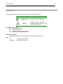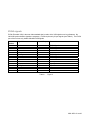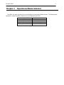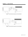
1
DURAVIS 3000 SERIES
User Manual
MNL-0551-01
revA2
REF. ECO-1390
Effective: 26-APR-07
Disclaimer
Although the information contained herein has been carefully verified, Parvus Corporation assumes no
responsibility for errors that might appear in this document, or for damage to property or persons resulting from
improper use of this manual or related software. Parvus reserves the right to change the contents and form of
this document, as well as the features and specifications of its products at any time without notice. The
information in this publication does not represent a commitment on the part of Parvus. This document contains
proprietary information that is protected by copyright. All rights are reserved. No part of this document may be
photocopied, reproduced, or translated into another language without the prior written consent of Parvus.
Parvus Corporation
3222 S. Washington St.
Salt Lake City, Utah, USA 84115
Phone: +1 (801) 483-1533
Toll-Free:
+1 (800) 483-3152
Main:
+1 (801) 483-1533
Fax:
+1 (801) 483-1523
Email:
Sales:
[email protected]
Support:
[email protected]
Web-site:
http://www.parvus.com
Send us your comments and feedback: [email protected]
Parvus is the U.S. arm of the Eurotech Group (www.eurotech.com), a global family of technology companies
focused on innovative embedded and high performance computing solutions.
Trademarks
Trademarks and registered trademarks appearing in this document are the property of their respective owners.
MNL-0551-01 revA2
DuraVIS 3000
3
IMPORTANT INFORMATION TO THE USER
Before proceeding further, please carefully read the following paragraphs:
Safety Notices and warnings
FCC information and compliance
This device has been designed to comply with the limits of a Class B digital device pursuant to Part 15 of the
FCC Rules. These limits are designed to provide reasonable protection against harmful interference. The device
generates, uses, and can radiate radio frequency energy and, if not installed and used in accordance with the
instructions, may cause harmful interference to radio communications or to devices that are not appropriately
shielded.
Parvus is not responsible for any radio or device, which may be affected by harmful interference. Appropriate
shielding of susceptible devices is not the responsibility of Parvus. Further, Parvus is not responsible for
unauthorized modifications of Parvus equipment including the substitution or attachment of cables and/or other
unauthorized equipment. If electrical interference is harmfully affecting a device, it is the responsibility of the user
to correct this interference.
In order to minimize the affects of electrical interference, use only shielded data cables with the system.
In accordance with FCC 15.21, changes or modifications not expressly approved by the party responsible for
compliance could void the user’s authority to operate the equipment.
Emissions information for Canada
This Class B digital apparatus complies with Canadian ICES-003. Cet appareil numérique de la classe B est
conforme à la norme NMB-003 du Canada.
CE Marking
This equipment complies with the requirements for CE marking when used in a residential,
commercial, vehicular or light industrial environment.
RAEE
The information below is issued in compliance with the regulations as set out by the 2002/96/CE directive,
subsequently superseded by 2003/108/CE, and refers electrical and electronic equipment and the management
of their waste (WEEE). When disposing of a device, including all of its components, subassemblies and
materials that are an integral part of the product, you should take the WEEE directive into consideration.
This symbol has been attached to the equipment or, in the case that this is not possible, on the
packaging, instruction literature and/or the guarantee sheet. By using this symbol it states that the
device has been marketed after August 13th 2005, and implies that you must separate all of its
components when possible, and dispose of them in accordance with local waste disposal legislations.
¾
Because of the substances present in the equipment, an improper use or disposal of the refuse can cause
damage to human health and to the environment.
¾
With reference to RAEE, it is compulsory to not dispose of the equipment with normal urban refuse,
arrangements should be instigated for separate collection and disposal.
¾
For more detailed information about recycling of RAEE, please contact your local waste
collection body.
¾
In case of illicit disposal, sanctions will be levied on transgressors.
Anti-static precautions
Always use appropriate antistatic precautions when handing any board. This is to avoid damage
caused by ESD (Electro Static Discharge).
MNL-0551-01 revA2
DuraVIS 3000
5
Conventions
The following table lists the conventions that are used throughout this manual.
Icon
Notice Type
Information note
Warning
Description
Important features or instructions
Information to alert you to potential
damage to a program, system or device
or potential personal injury
The “Mode” of the register:
R/W Read and write register.
RO Read only register.
W
Meaning of the register when written.
R
Meaning of the register when read.
Hexadecimal numbers:
Hexadecimal numbers are indicated with an “h” suffix (for example: 11Ch).
Other:
NC
Not internally connected
Reserved
Use reserved to Factory
Table of Contents
Disclaimer .............................................................................................................................................................2
Trademarks ...........................................................................................................................................................2
IMPORTANT INFORMATION TO THE USER .....................................................................................................3
Safety Notices and warnings..........................................................................................................................3
RAEE..............................................................................................................................................................4
Anti-static precautions...........................................................................................................................................4
Conventions ..........................................................................................................................................................5
Table of Contents ...................................................................................................................................................6
Chapter 1 Introduction .......................................................................................................................................7
Overview.........................................................................................................................................................7
Chapter 2 Video Port Pin-outs...........................................................................................................................9
DVGA/VGA signals ........................................................................................................................................9
EVGA signals .............................................................................................................................................. 10
Chapter 3
Operational Mode Indicator .......................................................................................................... 11
Chapter 4 User Controls ................................................................................................................................. 12
Power-up Control ........................................................................................................................................ 13
After power-on ............................................................................................................................................. 14
Back of LCD ................................................................................................................................................ 14
Chapter 5 Troubleshooting............................................................................................................................. 15
Normal Care ................................................................................................................................................ 15
Technical/Sales Assistance......................................................................................................................... 15
Returning For Service ................................................................................................................................. 15
Appendix .............................................................................................................................................................. 16
Environmental Testing ....................................................................................................................................... 16
LIMITED WARRANTY ....................................................................................................................................... 17
MNL-0551-01 revA2
DuraVIS 3000
Chapter 1
7
Introduction
Overview
The DuraVIS 3000 is an LED backlit display that includes internal shock mitigation as well as digital
intensity control. Signals from a 640x480 VGA source are used to drive the display. The following information is
supplied as a description of the state of this product and some of the options that are available.
Function Highlights
•
The VGA inputs are through a Standard VGA connector. Additional signals are assigned on the
outputs of the Video Driver and the input to the Display. The pin assignments are listed in Chapter 2.
•
The DuraVIS 3000 requires a 14 to 35 VDC power source. To ensure a clear picture, use a shielded
cable for incoming power. The power can be supplied by either video DB15HD Connectors.
•
Input power has an EMI pi filter configuration.
•
The display is reverse bias protected.
•
Display orientation can be inverted(see Chapter 4)
•
The backlight offers 30 levels of brightness at over eight hundred nit.
Durability
•
The case is made of anodized black 6061T6 aluminum for EMI shielding.
•
The LCD is cradled in a molded shock cushion for high vibration and shock operation.
•
The acrylic window can take a heavy sharp blow without damage to the LCD, although, the window
may be scratched.
•
The front protective window is anti-reflective coated and ITO coated for glare and EMI control.
•
Vinyl protective sheet is placed over the display screen during shipping to prevent damage.
•
An external protective boot is available for added handling protection.
MNL-0551-01 revA2
DuraVIS 3000
Chapter 2
9
Video Port Pin-outs
The DuraVIS 3000 is equipped with two DB15HD input ports: One that is labeled DVGA/VGA and the other
labeled EVGA. Input power is applied on pins 11 and 12 of either input port. You can supply the power on the
same connector as the video signal, or you can supply power on the unused connector. For Instance, if you
were supplying an EVGA signal, you could apply the power to the EVGA connector or the DVGA/VGA
connector. Be sure to only use one power supply.
The following tables indicate the pin-outs of the video ports of the DuraVIS 3000. Figure 2 depicts the
signal names and pin assignments for the DVGA/VGA high density DB 15 connector. Figure 3 depicts the pinout of the EVGA high density DB 15 connector.
DVGA/VGA signals
DVGA (Differential VGA) is a video format created by Parvus Corporation to drive VGA signals over long
distances. DVGA requires all of the signals of a regular VGA cable plus pins 9 and 10. See Table 1.
The DVGA/VGA port on the display is able to handle two video formats: DVGA and VGA. The display will
automatically detect the video format (VGA or DVGA) and display the video image to the LCD.
The VGA/DVGA interface will support Standard VGA or Parvus Differential Sync VGA via this connector. The
Video pin-out signal connections are shown in the table below. NOTE: While the display supports VESA VGA
signals, the interface connector is NOT a VESA VGA port. Care should be taken when connecting to this port to
ensure proper signal connections. When used with VESA VGA only the 9 Video signals should be connected,
with all other pins left unconnected. A PC DB15HD VGA Cable should not be used with this interface connector.
Pin
Number
1
2
3
4
5
6
7
8
9
10
11
12
13
14
15
Signal Name
Input / Output
Comments
Red
Green
Blue
N/C
N/C
Red Return
Green Return
Blue Return
Horizontal Sync Vertical Sync VIN
GND_IN
Horizontal Sync +
Vertical Sync +
N/C
Input
Input
Input
VGA Signal
VGA Signal
VGA Signal
Input
Input
Input
Input
Input
Input
Input
Input
Input
VGA Signal
VGA Signal
VGA Signal
Differential Video Signal (optional)
Differential Video Signal (optional)
Input Power
Input Power
VGA Signal
VGA Signal
Table 1.
Figure 1
EVGA signals
EVGA (Encoded VGA) is the new video standard that is used to drive VGA signals over long distances. No
individual synchronization signals are necessary. EVGA requires only 6 input signals (see Table 2). The EVGA
port of the unit can only handle 640x480 EVGA signals.
Pin
Number
1
2
3
4
5
6
7
8
9
10
11
12
13
14
15
Signal Name
Input / Output
Comments
Red
Green
Blue
Reserved
N/C
Red Return
Green Return
Blue Return
Reserved
N/C
VIN
GND_IN
Reserved
Reserved
N/C
Input
Input
Input
EVGA Signal
EVGA Signal
EVGA Signal
Input
Input
Input
EVGA Signal
EVGA Signal
EVGA Signal
Input
Input
Input Power
Input Power
Table 2.
Figure 3
MNL-0551-01 revA2
DuraVIS 3000
Chapter 3
11
Operational Mode Indicator
The LED in the upper right-hand corner of the display is the Operational Mode Indicator. The following table
indicates the modes of operation based on the color displayed by the LED:
Color of the LED
Red
Green
Blue
Flashing Red and Green
Figure 4
Operational Mode
No Video
Video
Initializing
Internal Error
Chapter 4
User Controls
Figure 2: Port and Pushbutton designations for the DuraVIS 3006-20
Figure 2: Port and Pushbutton designations for the DuraVIS 3006-00
MNL-0551-01 revA2
DuraVIS 3000
13
Power-up Control
The following settings are applied by powering up the display while holding the indicated buttons for the
settings/operations listed. It should be noted that the behavior of the buttons is different during power-on than
while running. When the display is positioned so that the buttons and LED are on the right side, it is in its
standard mounting mode and the display is described as right-side up.
Factory Reset:
Simultaneously press the Up and Down buttons while powering on the unit to return to
factory defaults. This sets the backlight to midrange intensity and sets the video to rightside up.
Invert Video:
If it is necessary to mount the display upside-down, the displayed image can be inverted
by holding the Down button while powering on the display. Important note: in inverted
mode, the buttons on the front swap functions. I.e. when the display is mounted upsidedown, the topmost button increases the backlight intensity and the bottommost button
decreases the backlight intensity.
Normal Video:
If the display has been inverted as discussed above, the display can be brought back to
normal video mode by holding the Up button during power-on.
After power-on
The following functions are done by using the buttons after the system has been powered up. It should be
noted that the function of the buttons is different when depressed during power on than after power on. When in
inverted video mode the Up and Down buttons swap; thus the topmost intensity button increases backlight
intensity.
Up:
Increase the intensity of the backlight.
Down:
Decrease the intensity of the backlight.
User Defined:
These keys are specified by the user.
Backlight Power:
This key turns the backlight off.
Back of LCD
Brightness:
Push and hold the brightness button while adjusting the brightness with the front
up/down keys. This will adjust the video signal brightness, not the backlight intensity.
Video Flip:
Push to flip the LCD display.
Contrast:
Push and hold the Contrast button while adjusting the contrast with the front up/down
keys.
Revision Info:
Push both the up and down buttons simultaneously to display the OSD Version
information.
MNL-0551-01 revA2
DuraVIS 3000
15
Chapter 5 Troubleshooting
Normal Care
The display can be cleaned with a soft cloth, warm soapy water, or alcohol.
The Cooling fins on the back of the display should not be covered
Technical/Sales Assistance
If you have a technical question or if you cannot isolate a problem with your display, please call or e-mail the
Parvus Technical Support:
¾
Email: [email protected]
¾
Phone: +1 (801) 483-1533
¾
Fax: +1 (801) 483-1523
If you have a sales-related question, please contact your local Sales Representative.
Returning For Service
Before returning any Parvus product, you must contact Parvus to obtain a Returned Material Authorization
(RMA) number.
Note. You must have the RMA number in order to return any product for any reason!
Pack the module in an anti-static material and ship it in a sturdy cardboard box with enough packing material to
adequately cushion it.
Warning! Any product returned to Parvus improperly packed will immediately void the warranty for
that particular product!
Appendix
Environmental Testing
MIL-STD-461E
Designed and Tested to the following standards:
• CE-102 Section 5.5; Power Leads, 10 kHz to 10 MHz, basic curve.
• RE-102 Section 5.16; Electric Field, 2 MHz to 18 GHz, two configurations, figure RE102-3
internal fixed wing < 25 meters.
MIL-STD-810F
Designed and Tested to the following standards:
• High Temperature Section 501
• Low Temperature Section 502
• Vibration Section 514
• Shock Section 516
MNL-0551-01 revA2
DuraVIS 3000
17
For more information about this or other products in the Parvus line of embedded systems solutions, call (801)
483-1533 from 8:00AM to 5:00PM Mountain Time, E-mail us at [email protected] or visit our web-site at:
http://www.parvus.com
LIMITED WARRANTY
Parvus Corporation warrants this product to be free of defects in materials and workmanship, and that the
product meets or exceeds the current specifications published by Parvus. This Warranty is valid for a period of
one (1) year from the date of purchase. Parvus reserves the right to repair or replace any Warranted products at
its sole discretion. Any product returned to Parvus for repair or replacement under the provisions of this warranty
must be accompanied by a valid Return Material Authorization (RMA) number issued by the Parvus Customer
Service Department.
Parvus Corporation makes no warranty not expressly set forth in this document. Parvus disclaims and excludes
all implied warranties of merchantability and fitness for a particular purpose. The aggregate liability of Parvus
arising from or relating to (regardless of the form of action or claim) is limited to the total of all payments made to
purchase the product. Parvus shall not in any case be liable for any special, incidental, consequential, indirect or
punitive damages, even if Parvus has been advised of the possibility of such damages. Parvus is not
responsible for lost profits or revenue, loss of the use of software, loss of data, costs of recreating lost data, or
the cost of any substitute equipment or program.
This Warranty shall be governed by the laws of the United States of America and the State of Utah, and any
claim brought under this Warranty may only be brought in state or federal court located in Salt Lake County,
State of Utah, and purchaser hereby consents to personal jurisdiction in such courts.
For further information contact:
Parvus® Corporation
3222 S. Washington St.
Salt Lake City, Utah, USA 84115
(801) 483-1533, FAX (801) 483-1523
Web-site: http://www.parvus.com