Download DigiCap II System Menu

Transcript
Version: V4.1
Doc No.: 2011020703
1
Table of Contents
About This Guide ------------------------------------------------------------------------------------------------- 4
FCC Compliance Statement ------------------------------------------------------------------------------------ 4
FCC Warning ------------------------------------------------------------------------------------------------------ 4
License Agreement ------------------------------------------------------------------------------------------------ 5
Trademark---------------------------------------------------------------------------------------------------------- 7
Customer Support ------------------------------------------------------------------------------------------------ 7
Chapter 1. Product Introduction------------------------------------------------------------------------------- 8
1-1. Product Package Content----------------------------------------------------------------------8
1-2. Product Overview ------------------------------------------------------------------------------9
Chapter 2. Hardware Installation ---------------------------------------------------------------------------- 24
2-1. Before You Proceed -------------------------------------------------------------------------- 24
2-2. Hardware Requirement ---------------------------------------------------------------------- 25
2-3. Central Process Unit (CPU) Installation -------------------------------------------------- 26
2-4. Memory Module Installation --------------------------------------------------------------- 28
2-5. HDD Installation ----------------------------------------------------------------------------- 29
2-6. PTZ Camera Installation -------------------------------------------------------------------- 31
Chapter 3. DVR Operating System ------------------------------------------------------------------------ 34
3-1. DVR System Control Panel Configuration ----------------------------------------------- 35
3-2. DVR Main Program ------------------------------------------------------------------------- 46
3-3. Program Overview --------------------------------------------------------------------------- 47
Chapter 4. DVR Software Operation ------------------------------------------------------------------------ 56
4-1. Surveillance Server (Witness Pro) --------------------------------------------------------- 56
4-2. Logging in the Surveillance Server -------------------------------------------------------- 61
4-3. Camera configuration------------------------------------------------------------------------ 62
4-4. Video playback / Synchronized playback / Text insert playback / ezBack ----------- 79
4-5. Network Configuration ---------------------------------------------------------------------- 95
4-6. System Configuration /Video display configuration/Connection ezDispatch Server setup/
Save/Load configuration / ezTools -------------------------------------------------------------100
4-7. User assess setup ----------------------------------------------------------------------------108
2
4-8. Application logs -----------------------------------------------------------------------------112
4-9. Peripherals setup ----------------------------------------------------------------------------114
4-10.Stop alarm siren -----------------------------------------------------------------------------118
4-11 .Storage configuration ----------------------------------------------------------------------118
4-12.Video Control Panel ------------------------------------------------------------------------121
Chapter 5. ezTools---------------------------------------------------------------------------------------------- 126
5-1. ezWebServer - IE Browse Server ---------------------------------------------------------126
5-2. ezRServer - Remote Control Server ------------------------------------------------------130
5-3. ezSTalk - Two-way voice Communication ---------------------------------------------133
5-4. ezReboot - Auto-restart the DVR machine ----------------------------------------------135
5-5. ezClock - Auto-synchronized time--------------------------------------------------------136
5-6. ezHDDSmart - HDD Health Checkup ---------------------------------------------------137
5-7. ezUPSCheck ---------------------------------------------------------------------------------140
5-8. ezMobileServer – MobileView Server ---------------------------------------------------141
5-9. Other Applications --------------------------------------------------------------------------142
Chapter 6. Remote Client PC Software ------------------------------------------------------------------- 147
6-1. Start Using FreeView Pro (Remote Client Program) --------------------------------147
6-2. Remote Client Program Operation--------------------------------------------------------148
Chapter 7. Mobile device remote viewing Software ---------------------------------------------------- 174
7-1. PDAView & MobileView program installation -----------------------------------------174
7-2. PDAView & MobileView Application ---------------------------------------------------175
7-3. ezMobileServer Application ---------------------------------------------------------------176
3
About This Guide
Conventions used in this guide to make sure that you perform certain tasks properly, take note of the following
symbols to use throughout this manual.
WARNING: Information to prevent injury to yourself when trying to complete a task.
CAUTION: Information to prevent damage to the components when trying to complete a task.
IMPORTANT: Information that you must follow to complete a task.
NOTE: Tips and additional information to aid in completing a task.
FCC Compliance Statement
This device complies with part 15 of the FCC Rules. Operation is subject to the following two conditions:
This device may not cause harmful interference, and this device must accept any interference received,
including interference that may cause undesired operation.
FCC Warning
This equipment has been tested and found to comply with the limits for a Class B digital device, pursuant to
Part 15 of the FCC Rules. These limits are designed to provide reasonable protection against harmful
interference in a residential installation. This equipment generates uses and can radiate radio frequency
energy and, if not installed and used in accordance with the instructions, may cause harmful interference to
radio communications. However, there is no guarantee that interference will not occur in a particular
installation. If this equipment does cause harmful interference to radio or television reception, which can be
determined by turning the equipment off and on, the user is encouraged to try to correct the interference by
one or more of the following measures:
z Reorient or relocate the receiving antenna.
z Increase the separation between the equipment and receiver.
z Connect the equipment into an outlet on a circuit different from that to which the receiver is connected.
z Consult the dealer or an experienced radio/TV technician for help.
z Shielded cables and I/O cords must be used for this equipment to comply with relevant FCC regulations.
4
License Agreement
Notice to end-user: please read the following legal agreement carefully. Use of the Witness or any of the
software provided with this agreement constitutes your acceptance of these terms. If you do not agree with
the terms of this agreement, PROMPTLY RETURN the Witness system, Witness, AnyView Pro and
FreeView Pro , any related software and the included items (including the Witness video system, written
materials and containers) to the location where you purchased them for a full refund.
1-1. License Grant. I-View grants to you (either as an individual or an entity) a personal, nonexclusive,
nontransferable license to use one copy of the executable code of the I-View's Witness, FreeView Pro
and AnyView Pro on a single CPU residing on your premises. The term of this Agreement will be for the
duration of I-View’s copyright in the Witness, FreeView Pro and AnyView Pro. You may assign your
rights under this Agreement to a third party who agrees in writing to be bound by this Agreement prior to
the assignment, and provided that you transfer all copies of the Witness, FreeView Pro and AnyView
Pro and related documentation to the third party or destroy any copies not transferred. Except as set forth
above, you may not assign your rights under this Agreement, nor shall you rent, lease, sell, sublicense or
otherwise transfer the Witness, FreeView Pro and AnyView Pro.
1-2. Reverse Engineering. You may not reverse engineer, decompile or otherwise disassemble the Witness,
FreeView Pro and AnyView Pro except to the extent that applicable law expressly prohibits this
restriction.
1-3. Copyright. Title and full ownership rights to the I-View's Witness, FreeView Pro and AnyView Pro will
remain the exclusive property of I-View or its suppliers, and you will not acquire any rights to the
I-View's Witness, FreeView Pro and AnyView Pro except as expressly set forth above.
1-4. Maintenance. I-View is not obligated to provide maintenance or updates to you for the Witness
system and transport to Witness, FreeView Pro and AnyView Pro. However, any maintenance or updates
by I-View shall be covered by the Agreement.
1-5. Disclaimer of Warranty. I-View warrants that the Witness system, the witness FreeView Pro and
AnyView Pro and related software will perform substantially in accordance with the accompanying
documentation and those CD-ROM diskettes are free from any defects for a period of 90 days from the
date of purchase (limited warranty). Except for the foregoing limited warranty, I-View expressly
disclaims any and all other warranties, whether express or implied, including without limitation, the
implied warranties of merchantability, fitness for a particular purpose, and non-infringement of third
5
party rights. If law does not permit such disclaimer of any implied warranty, the duration of any such
implied warranties is limited to 90 days from the date of purchase. Some countries do not allow the
disclaimer of implied warranties, limitations on how long an implied warranty lasts, or the exclusion or
limitation of incidental or consequential damages, so such limitation as or exclusions may not apply to
you. This warranty gives you specific legal rights and you may also have other rights, which vary, from
state to state.
1-6. Customer Remedies. In the event the Witness system or related software does not meet or conform to
the Limited Warranty, I-View’s entire liability and your sole and exclusive remedy shall be, at I-View's
option, either to (a) correct the error, (b) help you work around or avoid the error or (c) authorize a refund
so long as the Witness system documentation and CD-ROM diskettes are returned to I-View with a copy
of your receipt. This Limited Warranty is void if failure of the Witness system has resulted from accident,
abuse, or application. Any replacement Witness system will be warranted for the remainder of the
original warranty period.
1-7. No Liability for Consequential Damages. In no event shall its suppliers be liable to you for any
incidental, indirect, special or consequential damages of any kind rising out of or related to this
agreement or use or inability to use the related software, even if I-View has been advised of the
possibility of such damages.
1-8. Please acknowledge that the laws and regulations of the Taiwan R. O. C. restrict the export and
re-export of commodities and technical data of Taiwan R. O. C. origin. You may not download or
otherwise export or re-export the Witness system or related software or any underlying information or
technology except in full compliance with all United States and other applicable laws and regulations.
You agree to indemnify and hold I-View harmless from and against any and all liability arising from or
relating to your breach of this Manual.
1-9. Governing Law; attorneys' fees. The laws of the Taiwan R. O. C will govern this agreement. Without
regard to conflict of law principles. The R. O. C. Convention on Contracts for the International Sale of
Goods is specifically disclaimed. The prevailing party shall be entitled to recover its reasonable attorneys'
fees in the event of a dispute arising out of or relating to this Agreement.
1-10. Entire Agreement. This is the entire agreement between you and I-View with respect to the use of the
Witness, FreeView Pro and AnyView Pro, which supersedes any prior agreement, whether written, or
oral, and all other communications between the parties relating to the subject matter of this Agreement.
6
Should you have any questions concerning this Agreement, please contact I-View directly at one of the
numbers or addresses listed at the beginning of this manual.
Trademark
DigiCap II, Deco, e-Witness, @-Witness Pro, u-Witness XP, x-Witness, FreeView Pro, AnyView Pro,
PDAVirw and MobileView are registered trademarks of I-View Communication Inc.
Microsoft, Windows 95, 98, ME, Windows2000, XP, Vista and 7 are registered trademarks of Microsoft
Corporation. All other trademarks are the property of their respective holders.
Customer Support
If technical problems arise with the use of our products in which you and your vendor cannot resolve, please
try the following: If you have an Internet connection, visit the I-View website http://www.i-view.com.tw
(Taiwan) for any software or product updates, or email to [email protected] (Taiwan) or Tel:
886-3-510-3001 Fax: 886-3-510-3002 (Taiwan). We are dedicated to providing the highest quality support.
E-mailing our tech support will give you the chance to document each of the above items in a very clear and
concise manner and will give our support team a chance to document any problems and respond with
thoroughly researched answers.
7
Chapter 1. Product Introduction
1-1. Product Package Content
Thank you for choosing the I-View Embedded DVR system. Before you start installing the
hardware devices with the DVR, please check the items of the product package with the list
below,
Application program CD and Nero CD
User manual & Power cable
2x SATA disk cable
Remote controller with battery
1 x 16 port Audio cable (For 32 channels Audio recording model)
1 x 16 channel video input cable (For Digi-9600XP/3296Pro Pro)
16 or 32 channels video loop cable (Optional)
16 or 32 channels Spot Monitor video out (Optional)
2 x Ear panel (For 19” Rack mount) and some screws.
USB Mouse & DVI to VGA converter (For second monitor)
If any of the above items is damaged or missing, contact your
retailer.
8
1-2. Product Overview
1-2-1. Front Panel of DVR System
The buttons of the front panel provides user to operate the DVR basic functions (e.g.
channel switching functions, display modes functions and playback functions … etc.),
however, user will need a mouse to connect with the DVR for more detail system setting.
Left Section of the DVR Front Panel (Fig 1-3-1.1)
Press “Number (0-9)+
“ to view just one camera’s image on the monitor or TV. For
example: When you select “ 1+6 +
“, then you will watch the channel 16 on monitor or TV.
Press
key to divide the window into 4 split screens.
Press
key to divide the window into 8 split screens.
Press
key to divide the window into 9 split screens.
Press “
1-16 ” key to divide the window into 16 split screens. (Camera 1 - 16)
Press “
17-32 ” key to divide the window into 16 split screens. (Camera 17 - 32) (For
Digi-3200Pro only)
Press “ Rotate “ key to rotate cameras views on screen automatically. Press “ 0 “ + “ Rotate
“ the rotation will be stopped. The detail settings please refer to Chapter 6-3.
Press
key to toggle between non real-time viewing (Recording mode) and real-time viewing
(Live view mode) of video displays. The detail settings please refer to Chapter 6-3.
Press
key will hide the tool bar of main screen until
Press
key that function same as enter or OK.
9
key is pressed again.
Middle Section of the DVR Front Panel (Fig 1-3-1.1 & Fig 1-3-1.2)
DVR NO.: Display for the ID address of DVR. The detail setting please refers to
Chapter 5-3.
HDD: Indicate the status of HDD.
Press “On/Off “ key to Turn on / off DVR.
Press “ Rec “ key to start recording the video. Press “ 0 “ + “ Rec “ the stop recording.
The detail settings please refer to Chapter 6-3.
Press “Map” to show the information and map of DVR. Press “ 0 “ + “ Map “ to
close the Map screen. The detail settings please refer to Chapter 7
Press “Login/Out” to login/logout of DigiCap II DVR. Press “ Cancel “ to close the
function.
Press “Mute” to stop the sound alarm when camera is triggered.
Press ► key to play back all videos.
Press
key once to pause all videos.
Press ■ key to stop playback all videos.
Press << key to jump to previous frame of all videos.
Press >> key to jump to next frame of all videos.
Press ◄◄ key to decreases the playback frame rate of all videos.
Press ►► key to increases the playback frame rate of all videos.
Press “ Info “ to list the information of all video clips, and you can quickly search and
assign a video clip to playback. Press “ 0 “ + “ Info “ to close this function.
Fig 1-2-1.1
10
Fig 1-2-1.2
Right Section of the DVR Front Panel (Fig 1-3-1.3)
Press
key to search for videos in database. Press “ 0 “ + “
“ to close the playback
function.
Press ► key to play back the video files which you select.
Press
key once to pause the video file which you select.
Press ■ key to stop playback the video file which you select.
Press << key to jump to previous frame of the video file, which you select.
Press >> key to jump to next frame of videos file which you select.
Press ◄◄ key to decreases the playback frame rate of video file, which you select.
Press ►► key to increases the playback frame rate of video file, which you select.
Press “ Pre ” key to jumps to the previous video, which you select.
Press “ Next ” key to jumps to the next video, which you select.
Press “ Back up “ key will copy current video clip to a specific location for archiving. Press “ 0
“ + “Back up “ to close the backup video file function.
Press “
“ key to capture the video screen as a BMP or JPEG format. Press “ 0 “ + “
close the backup picture file function.
Press ▲(Up ), ►(Right), ▼(Down) and ◄(Left) key to select the item.
Press ” OK “ key to enter the selection item.
Press ” Tab“ key to change the section.
Press ” Select “ key to enter the selection item.
Press ” Cancel “ key to quick the selection item.
Fig 1-2-1.3
11
“ to
1-2-2. Back Panel of DVR System
According to the different model of the DigiCap DVR, their back panel configuration
may be different, please read carefully the introduction below.
z Digi-9600XP /Digi-9600XP-A Back Panel description:
1. Power plug: Plug power cable.
2. Power switch: Turn on/off power supply.
3. RS-485 Port: The communication port to control the Speed Dome and P/T/Z
camera.
4. Series port: Connect to RS-232 device such as Modem..
5. Printer port: Connect to the printer.
6. Panic button port: Connect to push button for emergency call. (Dry contact
input only).
7. USB port: Connect to USB device, such as USB external storage device.
8. LAN port: For TCP/IP connection.
9. Audio plug: Including Microphone in / Speaker out /Line in.
10. VGA port: The first Monitor VGA port.
11. DVI port: The second monitor connection port.
12. Video input: The 16 (17-32) video input.
13. Audio input: 17-32 audio input. (For Digi-9600XP-A only).
12
14. Video loop output: The optional 16 (1-16) cameras video loop output.
15. Video loop output: The optional 16 (17-32) cameras video loop output.
16. Video input: The 16 (1-16) video input.
17. Sensor input: 16 sensors input. (For Dry contact input only).
18. Main Monitor 0 output: Display 1-16 spilt video on TV.
19. Main Monitor 1 output: Display 17-32 spilt video on TV.
20.. Relay output: 3 relay output.
21. Audio input: 1-16 audio input. (For Digi-9600XP-A only).
22. Spot Monitor 0 output: The optional 16 (1-16) cameras spot monitor 0 output.
23. Spot Monitor 1 output: The optional 16 (17-32) cameras spot monitor 0 output.
The video looping video cannot be used when add the Spot monitor video out.
z Digi-4800XP /Digi-4800XP-A Back Panel description:
1. Power plug: Plug power cable.
2. Power switch: Turn on/off power supply.
3. RS-485 Port: The communication port to control the Speed Dome and P/T/Z camera.
4. Series port: Connect to RS-232 device such as Modem.
5. Printer port: Connect to the printer.
6. Panic button port: Connect to push button for emergency call. (Dry contact input only)
13
7. USB port: Connect to USB device, such as USB external storage device.
8. LAN port: For TCP/IP connection.
9. Audio plug: Including Microphone in / Speaker out /Line in..
10. VGA port: The first Monitor VGA port.
11. DVI port: The second monitor connection port.
12. Video loop output: The optional 16 (1-16) cameras video loop output.
13. Video input: The 16 (1-16) video input.
14. Sensor input: 16 sensors input. (For Dry contact input only).
15. Main Monitor 0 output: Display 1-16 spilt video on TV.
16. Revise:
17.. Relay output: 3 relay output.
18. Audio input: 1-16 audio input. (For Digi-4800XP-A only)
19. Spot Monitor 0 output: The optional 16 (1-16) cameras spot monitor 0 output.
The video looping video cannot be used when add the Spot monitor video out.
z Digi-3296Pro/3296Pro-A Back Panel Description:
1.
Power plug: Plug power cable.
2.
Power switch: Turn on/off power supply.
3.
RS-485 Port: The communication port to control the Speed Dome and P/T/Z camera.
14
4.
Series port: Connect to RS-232 device such as Modem.
5.
Printer port: Connect to the printer.
6.
Panic button port: Connect to push button for emergency call. (Dry contact input only)
7.
USB port: Connect to USB device, such as USB external storage device.
8.
LAN port: For TCP/IP connection.
9.
Audio plug: Including Microphone in / Speaker out /Line in..
10. VGA port: The first Monitor VGA port.
11. DVI port: The second monitor connection port.
12. Single video output: The1-16 single video output.
13. Video input: The 16 (17-32) video input.
14. Audio input: 17-32 audio input. (For Digi-3296Pro-Aonly)
15. Video loop output: The optional 16 (1-16) cameras video loop output.
16. Video loop output: The optional 16 (17-32) cameras video loop output.
17. Video input: The 16 (1-16) video input.
18. Sensor input: 16 sensors input. (For Dry contact input only).
19. Main Monitor 0 output: Display 1-16 spilt video on TV.
20. Main Monitor 1 output: Display 17-32 spilt video on TV.
21.. Relay output: 3 relay output.
22. Audio input: 1-16 audio input. (For Digi-3296Pro-Aonly)
23. Video out: Display 17-32 single video on TV.
24. Spot Monitor 0 output: The optional 16 (1-16) cameras spot monitor 0 output.
25. Spot Monitor 1 output: The optional 16 (17-32) cameras spot monitor 0 output..
The video looping video cannot be used when add the Spot monitor video out.
15
z Digi-3248Pro/3248Pro-A Back Panel Description:
1.
Power plug: Plug power cable.
2.
Power switch: Turn on/off power supply.
3.
RS-485 Port: The communication port to control the Speed Dome and P/T/Z camera.
4.
Series port: Connect to RS-232 device such as Modem.
5.
Printer port: Connect to the printer.
6.
Panic button port: Connect to push button for emergency call. (Dry contact input only)
7.
USB port: Connect to USB device, such as USB external storage device.
8.
LAN port: For TCP/IP connection.
9.
Audio plug: Including Microphone in / Speaker out /Line in..
10. VGA port: The first Monitor VGA port.
11. DVI port: The second monitor connection port.
12. Single video output: The1-16 single video output.
13. Video input: The 16 (17-32) video input.
14. Video loop output: The optional 16 (1-16) cameras video loop output.
15. Video loop output: The optional 16 (17-32) cameras video loop output.
16. Video input: The 16 (1-16) video input.
17. Sensor input: 16 sensors input. (For Dry contact input only).
18. Main Monitor 0 output: Display 1-16 spilt video on TV.
16
19. Main Monitor 1 output: Display 17-32 spilt video on TV.
20.. Relay output: 3 relay output.
21. Audio input: 1-16 audio input. (For Digi-3248Pro-Aonly)
22. Video out: Display 17-32 single video on TV.
23. Spot Monitor 0 output: The optional 16 (1-16) cameras spot monitor 0 output.
24. Spot Monitor 1 output: The optional 16 (17-32) cameras spot monitor 0 output.
The video looping video cannot be used when add the Spot monitor video out.
z Digi-1648 Pro Back Panel Description:
1. Power plug: Plug power cable.
2. Power switch: Turn on/off power supply.
3. RS-485 Port: The communication port to control the Speed Dome and P/T/Z camera.
4. Printer port: Connect to the printer.
5. Series port: Connect to RS-232 device such as Modem.
6. Panic button port: Connect to push button for emergency call. (Dry contact input )
7. USB port: Connect to USB device, such as USB external storage device.
8. LAN port: For TCP/IP connection.
9. Audio plug: Including Mic in / Speaker out /Line in.
10. VGA port: The first Monitor VGA port.
11. DVI port: The second monitor connection port.
17
12. Video loop output: The optional 16 (1-16) cameras video loop
13. Video in: 1-16 cameras video input.
14. Sensor input: 16 sensors input. (For Dry contact input only)
15. Main Spot Monitor 0 output: Display 1-16 split video on TV.
16. Video out: Display 1-16 single video output.
17. Relay output: 3 relay output.
18. Audio input: 1-16 audio input. (For Digi-1648 Pro-A only)
19. Spot Monitor 0 output: The optional 16 (1-16) Spot Monitor 0 output. (Option)
The video looping video cannot be used when add the Spot monitor video out.
18
1-2-3. DVR Remote Controller Functions
48 keys Remote controller
The buttons functions of the remote controller are for user to operate the DVR basic
functions (e.g. channel switching functions, display modes functions and playback
functions … etc.), however, user will need a mouse to connect with the DVR for detail
system setting.
Playback single video file
If you want to playback the single video clip, press “ S Play “ key and then select the function key
of playback.
Playback multi videos file
If you want to playback the single video clip, press “ M Play “ key and then select the function key
of playback. (Default is M Play mode) The he functions in Remote controller behave similarly of
chapter 5-2 Middle Near Panel.
Display single video out on TV
If you want to control the Single video out on TV, press “Number key+ S Play “ displays the single
video on TV. For example: When you select “ 1+6 + S Play “, then you will watch the channel
16 on monitor or TV. Press “0 + S Play “ to rotate all camera on TV.
Display split-screen video out on TV
Press the “ Number key +
function key “or “
directly to show single or split-screen video on TV.
19
,
,
,
1-16 or
17-32 ” key
27 keys Remote controller (Optional)
This remote controller special design for the spot monitor application. On your remote controller,
there should be buttons labeled with function button and numbers representing the main
monitor/spot Monitor and camera numbers. Points the remote controller at the sensor/receiver,
press the number of the camera you wish you to on the TV and it would appear.
z
Number key: For the video channels selections. Simply press the number key from the
“Display” section to display the selected video channel on the connected monitor.
z
Return (Single video out): To return back to the channels scrolling display mode while in the
signal video display mode.
z
F1: Press F1 button to assign the video out of Main Monitor 0 to show on the TV.
z
F2: The Press F2 button to assign the Single TV out (1-16) of DVR to show on the TV.
z
F3: Press F3 button to assign the video out of Main Monitor 1 to show on the TV.
z
F4: Press F4 button to assign the Single TV out (17-32) of DVR to show on the TV.
z
Split Section: Push the splitter key on “ Split ” section, and then you will watch the splitter
video on TV. (Click the ● icon to change 6, 10, 13 split screen sequence).
z
Return: After you use Display function, then you will return to all channels scroll.
z
Enter: Press the Enter button to display OSD Menu on the TV.
1.
When you press the Enter, then F1 button that the control will become to “ 2 MUX + Single
TV Out “Mode. You can control the Single TV and split video output separately, the “ Main
monitor 0 & Spot Monitor 0 “ and “ Main monitor 1 & Spot Monitor 1 “ will synchronize the
video display. The control button as below:
— Press F1 button to control the main monitor 0 and spot Monitor 0 display.
— Press F2 button to control the Single TV Out (1-16).
20
— Press F3 button to control the main monitor 1 and spot Monitor 1 display.
— Press F4 button to control the Single TV Out (17-32)
2. When you press the Enter, then F2 button that the control will become to “ 4 MUX “ mode.
You can control Main monitor 0, Main monitor 1, Spot Monitor 0 and Spot Monitor 1
separately. The control button as below:
— Press F1 button to control the main monitor 0 display.
— Press F2 button to control the spot monitor 0 display.
— Press F3 button to control the main monitor 1 display.
— Press F4 button to control the spot monitor 1 display.
For example:
1. If you want to view the camera 22 of single TV out on TV; click “ Enter “ button, then
Press “ F4 “ button and then entry “ 6 “ number key, you will watch the camera 22 single
video on TV.
2. If you want to view the 4 split video (Camera 1-4) of Spot Monitor 1 on TV; click
“ Enter “ button, then Press “ F1 “ button and then entry “ 4 split way“ button, you will
watch the camera 4 split video on TV.
Sensor cable
To install the sensor, simply plug the end of the sensor device (“1” connector) into the Sensor
connector of inside of DVR. There is a phone jack on each board of DVR, this port for the
sensor input. All the signal of sensor link together, so plug a sensor that can control all main
monitor and spot monitor display at a time if all TVs at a same place.
1. Please shut down the power of DVR when you plug in the sensor cable into the board,
otherwise it will cause the sensor damage.
2. Make sure that the sensor itself is not covered and is facing the place from where you
will be using the remote controller.
3. Do not use 27 Keys remote controller on the DVR site, because the DVR
will be reset when press “ F4 “ button of 27 Keys remote controller.
4. Make sure that the sensor itself plug into the phone jack completely.
21
(Fig
5. The system allows to extent sensor cable for control the TV out from far away site via
Remote Controller. Please follow the process as below to achieve this function:
a. Please use the shading cable such as 28#2C+S type.
b. The sensor cable includes 3-wire cable: Red (DC 5V), Shading cable (Ground),
White (Signal).
c. Using Standard Cat. 6 STP cable can extension sensor signal and power up to 300
meters, this test result just for reference only and you still need to do the
environment testing for the application.
Control multi DVRs via single Remote controller
Sometime there are several DVR in one place. Please follow the below steps to control
multi DVR via single Remote controller:
1. There is a Dip switch on the inside of front panel for the setting ID address of DVR,
the setting description as below:
↑: Disable
↓: Enable, S5-S8: No function
S1-S4: For ID address setting; the table of ID address as below
Switch
0
1
2
3
4
5
6
7
8
9
10
11
12
13
14
15
↑
↑
↑
↑
↓
↓
↓
↓
↑
↓
↓
↓
↓
↑
↓
↓
↑
↑
↓
↓
↓
↓
↑
↓
↑
↓
↑
↓
↓
↑
↑
↓
↑
↑
↑
↓
↓
↓
↓
↑
↑
↓
↓
↑
↓
↑
↓
↑
↑
↑
↓
↑
↓
↓
↑
↑
↑
↓
↑
↑
↓
↑
↑
↑
ID
S1
S2
S3
S4
2. It will show the ID address on the LED of front panel after your setting Dipswitch.
The default ID address is “ 0 ”. It does not need to change the setting when use a DVR
only. Control the DVR via Remote controller directly.
The keypad of front panel will be no function when the LED is flashing.
3. Press “ ID “ key and then select the “Number “ of DVR, which you want to control. The
22
number LED of front panel will be flashed. You can start to use the Remote controller when the
LED is flashing.
4. Press “ Return “ key to stop the function of Remote controller.
23
Chapter 2. Hardware Installation
After user finish the CPU, RAM and HDD installation, please remember to go to the system Control
Panel to configure the DVR system for installed hardware devices operating properly. For detail about
the setup DVR system configuration in control panel, please refer to chapter 3-1 DVR systems
Control Panel Configuration.
2-1. Before You Proceed
Take note of the following precaution before you install the components (CPU, HDD and RAM).
1. Unplug the power cord from the wall socket before touching any component.
2. Use a grounded wrist strap or touch a safety grounded object or to metal object, such as
the power supply case. Before handing components to avoid damaging them due to
static electricity.
3. Hold components by the edges to avoid touching the ICs on them.
4. Whenever you uninstall any components, place it on a grounded antistatic pad or in the
bag that came with the component..
5. Before you install or remove any component, ensure that the power supply is switched off
or the power cord is detached from the power supply. Failure to do so may cause severe
damage to DVR, peripherals, and/or components.
24
2-2. Hardware Requirement
z CPU & RAM request, please refer to the table 2-2.1.
z 7200RMP hard drive speed or better recommended.
z Recommend to use the 32M Bytes or better buffer.
z Please use 7200 RMP HDD when you user 32 channels or Digi4800/9600 XP DVR.
z Speakers are required for sound alarm/effects.
z Microphone with 2Vp-p output required for audio recording.
Table 2-2.1.
Item
CPU
RAM
Digi-4800 XP
Q8200 or better
2 GB
Digi-9600 XP
Q8200 or better
2 GB
Digi-1648 Pro
E2200 or better
2 GB
Recording rate
Model
Digi-3248 Pro
Digi-3296 Pro
Duo E5300 or
2 GB
better
Q8200 or better
2 GB
25
400/480 fps Full
D1
800/960 fps Full
D1
400/480 fps CIF
400/480 fps CIF
400/480 fps CIF
2-3. Central Process Unit (CPU) Installation
2-3-1. CPU Installations: Power Management Setup
The DVR’s board comes with a surface mount Socket 775 (LGA775) design for Intel Pentium 4
Processor in the 755-land package.
Fig.2-3-1.1
Fig.2-3-1.2
Fig.2-3-1.3
Fig.2-3-1.4
Fig.2-3-1.5
Fig. 2-3-1.6
Follow the steps below for CPU installation
1.) Locate the CPU socket on the platform. (Fig. 2-3.1).
2.) Press the load lever with your thumb (A) and remove it to the left (B) until it is released from the
retention tab. (Fig. 2-3.2)
3.) Lift the load lever in the direction of arrow to a 135-degree angle. (Fig. 2-3.3).
4.) Lift the load plate with your thumb and forefinger to a 100-degree angle (A), and then push the
PnP cap from the load plate window to remove (B). (Fig. 2-3.4).
5.) Position the CPU over the socket, making sure that the gold triangle is on the bottom-left corner
of the socket. The socket alignment key should fit into the CPU notch. (Fig. 2-3.5).
26
6.) Close the load plate (A), then push the load lever (B) until it snaps into the retention tab. (Fig.
2-3.6) The CPU fits in only correct orientation.
1. Unplug the power cord from the wall socket before touching any component.
2. DO NOT force the CPU into the socket to prevent bending the connectors on the
socket and damage the CPU!
Fig. 2-3.7
Fig. 2-3.8
2-3-2. The heat sink and fan installation
1.) Place the heat sink on the top of the installed CPU, making sure that the four fasteners match
the hole of platform.
2.) Push down two fasteners at a time in a diagonal sequence to secure the heat sink and fan
assembly in place.
27
2-4. Memory Module Installation
The Platform comes with Double Data Rate II (DDR II ) socket. These sockets support up to 4 GB
system memory.
For optimum capability, it is recommended that you obtain memory modules from the same
vendor.
The following figure shows the location of DDR II sockets and steps to install a RAM.
1. Unlock a socket by pressing the retaining clips outward.
2. Align a DIMM on the socket such that the notch on the DIMM matches the break on the socket.
3. Firmly insert the DIMM into socket until the retaining clips snap back in place and the DIMM is
properly seated.
Make sure to unplug the power supply before adding or moving DIMMs or other system
components. Failure to do so may cause severe damage to both the platform and the
components.
28
2-5. HDD Installation
The Platform of Digi-1648Pro/3248Pro/3296Pro comes with 1 IDE sockets (1st and 2nd IDE) and 7
(5+2; 2 HDDs for backup) pcs x SATA II sockets. The DigiCap II series DVR support up to 6 pcs x
SATA II HDD.
The default setting of the manufacture for the 1st IDE socket is used of the DVD+-RW and
flash memory.
Please follow the steps below to install the Series ATA/SATA II Hard disk.
Step 1. Remove the case cover of the DigiCap II Series DVR.
Step 2. Use the SATA/SATA II cable(s) to connect with the hard drive(s) (SATA II HDD) and
the motherboard connectors(s) (SATA cable for the SATA II slot) as showing in Fig.
2-6.1.
Fig. 2-6.1 SATA socket
If user tries to install the SATA/SATA II hard drive(s) for DigiCap II image storage, please
use SATA cable(s) to connect with the SATA/SATA II/III hard drive(s) and the
motherboard SATA slots for optimum data transmission performance.
Step 3. Connect the inner power cables with each hard drives as showing in Fig.2-6.2.
29
Step 4. Mount the connected hard drives into the DigiCap II inner chassis 1 and chassis 2 as
showing in Fig 2-6.3 (Allows to install 6 HDD up to 12TB by optional extra RAID
interface).
Step 5. Screw backs the DigiCap II case cover to complete the HDDs installation.
Fig. 2-6.2
Fig 2-6.3 Chassis 1 and 2 for hard drive(s) installation
30
2-6. PTZ Camera Installation
z Speed dome camera Installation:
z P/T Motor Installation:
The last NC-180AZ PTZ Receiver must be terminated.
31
z
Speed dome controlling port description:
„ Pin assignment:
RS-485 & Relay out
R1: Relay #1 out
R2: Relay #2 out
R3: Relay #3 out
Y: Transmitter (TX +) Z: Transmitter (TX-)
A: Receiver (RX+)
B: Receiver (RX-)
„ Relays output: Connect one voltage line and ground of Controller (Such as light) to
the desired “Relay output” number of Control Board.
„ RS-485: Connect to NC-180AZ PTZ Receiver or Speed dome camera.
„ Dip switch of Control Board:
The dip switch for the bound rate setting, please refer to the table as below:
Baud rate
1200
2400
4800
9600
Pin
z
Pin 1 & Pin 2
Short Open Short Open
Pin 3 & Pin 4
Short Short Open Open
Digital input Module:
G1 – G3: Common 1: Sensor #1 in
2: Sensor #2 in
3: Sensor #3 in
4: Sensor #4 in
5: Sensor #5 in
6: Sensor #6in
7: Sensor #7 in
8: Sensor #8 in
9: Sensor #9 in
10: Sensor #10 in
11: Sensor #11 in
12: Sensor #12 in
13: Sensor #13 in 14: Sensor #14 in
15:Sensor #15 in
16: Sensor #16 in
z
Sensors in: Each sensor-in port can receive trigger signals from other device to
trigger video recording, alarm and notify function. Please use the dry contact for
the sensor in; otherwise it will cause the damage of sensor input.
32
1. The “Sensor In” port for Dry contact input only, otherwise it will cause the device
damage.
2. The “Relay Out” port for NO (Normal Open) type device only.
3. The current must be less than 10A, when controlling electric device to relay output.
33
Chapter 3. DVR Operating System
z
DVR System Main Screen
Take note of the following precaution before you start to configure the DVR system.
1. The DigiCap II provides Bar-bond system for the distributor, therefore it dose NOT include the
HDD and License of Embedded XP. So you must install the HDD first by yourself. Especially
you MUST buy the license of Embedded XP from Microsoft, otherwise using the O.S. will
be ILLEGALITY.
2. You MUST obey the rules of Microsoft to process the license of Embedded. XP.
3. To avoid the virus problem, please remove the LAN cable and reboot DVR system when you
start to setup the DVR system configuration.
34
3-1. DVR System Control Panel Configuration
Once user has finished the CPU, RAM and HDD installation, please click the Control
Panel icon ( ) from the right side bottom corner of the DVR system main screen to
configure the DVR system.
z DVR System Main Screen
Control Panel Icon (
), Please click
to enter the “Control Panel”
z DVR System Control Panel
35
z Control Panel Function Description:
A just Date/Time– To adjust the system time clock.
Setup Network Connections– To setup the system network configuration.
Display Properties– To setup the system VGA display.
Disk Management– To format hard disk when you install a new hard device.
Setup Shared Folders– To setup the proper sharing folders for TCP/IP user.
Adjust Volume Control –To adjust the system sound volume.
Save System Setting– Press to make system configuration change effectively.
Auto Dialup- ezDialup– Allow you to auto dial up the 3G modem to connect the Internet
when turn on the Witness Pro program.
Auto enable program when
turn on the DVR.
Auto to Dialup 3G
Enable Modem
Entry the password and user
name for auto login
Save the setting parameters
Entry the phone
Connect to the Internet
Hang up the modem
36
Set Up Password– Allows you to setup a password to secure the system parameters of the
DVR.
Set up password to access the
control panel.
Set up password for shutdown
the DVR system.
Fig. 3-1.1 Set Up
Keyboard– Click this icon to display a mini keyboard on the screen for words input.
Return– To return to the DVR system main screen.
37
3-1-1. Adjust Date / Time.
Please click
icon from Control Panel to set DVR system “Date & Time”, “Time Zone” and
“Internet Time”.
Fig. 3-1-1.1 Adjust
3-1-2. Setup Network Connections
To have DVR remote monitoring and controlling capabilities, user needs to connect DVR with
Internet, and set up Network Connections configuration. Please follow the steps below to set up
Network configuration.
1. Click
icon on the control panel to enter Network Connection configuration display.
Fig. 3-1-2.1 Local Area Connection
2. Click mouse right button on the “Local Area Connection” icon and select “Properties “item to
38
enter the “Local Area Connection Properties” display.
3. Double click the “Internet Protocol (TCP/IP) “item to enter the “Internet Protocol (TCP/IP)
Properties”. Fill out the IP information in each section and press “OK” button twice to
complete.
Fig. 3-1-2.2 Internet Protocol (TCP/IP)
For detail about your network IP address setup, please contact your network supervisor or
Local ISP provider for more information.
39
3-1-3. Display Properties
To set up the DVR VGA card display property, simply click the
icon on the control panel to
enter the “Display properties” interface and press the “Settings” tap on the top for “Screen resolution”
and “Color Quality” setting.
Fig. 3-1-3.1System Display
As Fig. 3-1-3.2 and Fig.3-1-3.3 showing, user can select dual monitor display while connect two
monitors with DigiCap DVR.
Fig. 3-1-3.3 Duel monitor display selection
Fig. 3-1-3.2 System Display Properties
While DigiCap II DVR connects two monitors, the default setting of the display properties is that the
first screen is the primary display and the second screen is the extension display as showing in
Fig.3-1-3.2. To set up the second monitor to be the primary display, simply select the number 2 icon
and check the “Extend my Windows desktop onto this monitor” as showing in Fig.3-1-3.3.
40
3-1-4. Disk Management
This chapter walks you through the hard drive formatting in DVR system when you install a brand
new hard disk. Please follow the steps below to format the hard disks.
1. Click
icon to display the “Disk Management” interface.
2. Click the mouse right button on the new installing HDD, and select “New partition “item.
Fig. 3-1-4.1 Select “New Partition”
3. Press “Next” to start the format process.
4. Select “Extended partition “item and click “Next” button to continue.
Fig. 3-1-4.2 Select “Extended Partition”
5. Click “Next” to specify partition size.
6. Click “Finish “icon to complete the new partition wizard.
7. Click mouse right button on the new HDD again, and select “New Logical Drive”.
41
Fig. 3-1-4.3 Select “New Logical Drive”
8. Click “Next” to continue.
9. Select “Logical drive “partition type, and clicks “Next” to continue.
Fig. 3-1-4.4 Select “Logical drive”
10. Select “Assign the following drive letter “item, and click “Next” to continue.
Fig. 3-1-4.5 Select “Assign the following
drive letter”.
42
11. Select “Format this partition with the following settings “item, and click “Next” to
continue.
Fig. 3-1-4.6 Select “Format this partition with the following
12. Click “Finish” to complete hard disk partition and format process.
13. Repeat Step 1-12 to format another Hard disk.
3-1-5. Setup Share Folders
This chapter will show you how to share the system folder (e.g. ClipPro folder) and to-be-view
video files for remote network users. Please follow up the steps below to setup system-sharing
folders.
1. Click
icon from the system control panel screen to display “Shared Folders” interface.
2. Select “Shares “folder, and click the “Action” button form the top, then select the “ New “ and
“ File Share “ item to continue.
Fig. 3-1-5.1 ActionÆNewÆFile Share
43
3. While the system displays a “Create A Shared Folder Wizard”, please click “Next” button to
continue.
Fig. 3-1-5.2 Create a Shared Folder
4.
Please click the “Browse” button to select a folder which user wants to share, and fill in the
“Share name” section, then press “Next” button and follow the instruction to complete the
shared folder sharing.
Fig. 3-1-5.3 Browse a share folder
1. You MUST share the Disk (Not folder) for remote client when you using the
ezLANPlayback program to playback the Video playback via LAN.
2. You MUST share the Folder for backup the video clips to Remote HDD via LAN when using
the ezBackup program.
3. There is a user account for remote access (Backup and playback video clips via LAN). You
need to Login for remote access. The User name is “guest” and password is “Guest”.
44
3-1-6. Adjust Volume Control
Please click the
icon on the system control panel screen to adjust the system volume.
Fig. 3-1-6.1 Adjust Volume Control
3-1-7. Saving System Information
To make the change effectively after modifying each DVR system configurations, user need to press
the “Save System Setting” (
) icon to complete the changes.
45
3-2. DVR Main Program
3-2-1. System Configuration Diagram
46
3-3. Program Overview
3-3-1. The main function description:
Video parameters setup - ezSetup: Enable/disable individual audio/video channels and
configure the audio source and video resolution settings.
DVR Surveillance Server – DigiCap II: It is the main DVR application software program
that provides on-site live video viewing, scheduled or motion triggered video recording, and
much more. It can also be utilized as a central video server to transmit video streams to a
remote PC via PSTN, ISDN, LAN or Internet (TCP/IP).
Single-file video playback - ezPlayback: An easier-to-use program allows you to playback
your video backups off-site, such as at the police station, but only one file at a time. You can
automatically include this program onto your backup media, see ezBackup for more details..
47
Text insert playback - ezTextPlayback: Playback the recorded video clips with text
transactions. You can search the video by text record or keywords, such as date/time, register,
goods or amount. Please refer to PTI-100 or FAC-500 Operation Manual .
Video files archiving - ezBackup: Share or back up your recorded video clips into other
storage devices, such as a HDD, CD/DVD drive, USB Flash drive, Zip drive, etc..
IE browser server - ezWebServer: View DVR security camera video images via the popular
Internet Explorer browser.
Remote control server - ezRServer: Allow full access to your DVR machine for remotely
technical assitance, or for remotely changing your DVR’s configuration.
You must use
ezRClient in FreeView Pro to make the connection between the remote PC and the DVR.
Auto-restart the DVR machine - ezReboot: We recommend to schedule the restart for DVR
machine at least once a week, especially prior to important events, in case you may have exited
the application temporarily and forgot to relaunch it.
Auto-synchronized time - ezClock: Synchronize DVR’s clock with an Internet Time Server.
Please referee to chapter 5-4 for detail setup and operation introduction.
2-way voice communication - ezTalk: Real-time voice communication between the DVR
machine operator and a remote PC technician. Both machines must be equipped with a
microphone and a pair of speakers. The interaction is similar to talk over with a pair of
walkie-talkies. This is especially useful when expensive telephone long distance charges apply
between the two locations.
HDD Health Checkup - ezHDDSmart: S.M.A.R.T. (Self Monitoring Analysis & Reporting
48
Technology) along with the HDD’s own inner sensors can detect physical weaknesses of the
hard disk drive. Our ezHDDSmart software program will report the HDD’s current health
status, disk reliability, failure prediction and related statistical information. Please refer to
chapter 5-6 for in-depth details.
Fingerprint Access Controller – ezFingerKey: Manage the system configuration and the
function usage for fingerprint access controller. Please refer to the fingerprint access controller
user manual for detail instruction.
Mobile phone browser server -ezMobileServer: View the camera video in local DVR via the
mobile phone which supports the GPRS, Wifi or 3G function. Such as iPhone, Gphone, Synbia
Phone, BlackBerry, Windows Phone..
Keyboard: Press to display a mini-keyboard for words input.
Control Panel Button: Press to enter control panel interface for system configuration.
Restart/Power Off Button: Press to select restart or power off the DigiCap II system.
49
3-3-2. Video parameters setup
Please click
icon on the main screen or click
to display the Video Parameters Setup window.
This setup window may differ greatly depending on your DVR model. See the instructions below
to modify the default settings.
Disable channel: This will disable the selected channel. It is important to disable the channels that
are not in use (no cameras are currently connected to them) so as to increase display and recording
speed.
Default button: Revert all of your changes to the original factory default settings.
Video System: There are two surveillance video standards, NTSC (North America and Japan) and
PAL (Europe and most other countries).
Resolution: You can select the video resolution which will affect both live feeds and recorded
clips. There are three options: 704 x 480 (4 CIF, NTSC), 704 x 240 (2 CIF, NTSC) and 352 x
240 (CIF, NTSC); 704 x 576 (4 CIF/PAL), 704 x 288 (2 CIF/PAL) and 352 x 288 (CIF, PAL)
Capture audio: You can record sound by a stand-alone microphone or audio camera if your DVR
50
model came with multiple audio ports. Each device chipset can support one audio channel. Select
one video channel (camera #) in which you want to associate the audio channel with.
OK: Click “OK” to accept all your settings and modifications.
Cancel: Click “Cancel” to discard your current changes.
1.
Devices List: Display the camera number with their corresponding settings. You can double
click one of cameras to set up the video system, recording resolution, capture audio or disable
device. Click “Set up all” button if you would like to change all cameras’ settings at once.
„ Individual function description for the “Video parameters setup” window:
z Double click “Camera 01” from device list for parameters setup
z Double click “Camera 01” from device list for parameters setup in Digi-4800/9800XP”.
a
b
51
Setup video quality:
a. Auto setup: The user can set up “Simplicity” or “Complexity” based the recording
environment. They can also select the video quality as “Excellent, Perfect Good, Normal, or
Bad” for the recording video. However, please note that the better the video quality the users
select, the larger the video file size will be.
b. Manual setup: The user can select “VBR”, “CBR”, and “Hybrid VBR” for the compression
mode.
¾ VBR (Variable Bit Rate): VBR files vary the amount of output data per time segment. It
allows a higher bit rate (and therefore more storage space) to be allocated to the more
complex segments of media files while less space is allocated to less complex segments.
¾ CBR (Constant Bit Rate): The rate at which a codec's output data should be consumed is
constant. CBR would not be the optimal choice for storage as it would not allocate enough
data for complex sections (resulting in degraded quality) while wasting data on simple
sections.
¾ Hybrid VBR: It is the neutral compression mode between VBR and CBR.
¾ GOP (Group of pictures): It is a group of successive pictures within a coded video stream.
Each coded video stream consists of successive GOPs. The higher the GOP, the smaller the
file size. However, if the bandwidth is not stable, the video quality will take some times to
become normal.
¾ Frame Rate: The user can decide the recording speed for the video.
¾ I-Frame QP: It is the least compressible but doesn't require other video frames to decode.
The user can adjust I-Frame to get the better video quality or reduce the video file size.
¾ P-Frame QP: It can use data from previous frames to decompress and is more
compressible than I-frames. The user can adjust P-Frame to get the better video quality or
reduce the video file size.
¾ Limit lowest QP (Quantization Parameter): The quantization parameter is a setting that
controls the quality of video compression in H.264. The user can set up the lowest acceptable
video quality for the video.
¾ QP step: It indicates how much the quantizer can change between two consecutive frames
52
¾ Compression bits rate: It will decide the video quality and file size. The higher
compression bits rate, the better the video quality, but the larger the file size. The user should
setup the compression bits rate when they select CBR and Hybrid VBR mode.
2.
Surveillance software control panel setup:
The user can change the positions (either left
or right of the screen) of the control panels in
the Witness Pro Application. You can
individually change the control panel for the
live cameras screen and/or the main playback
screen.
„ Left side video control panel
„ Right side video control panel
3. Audio recording setup (from sound card):
The user can record the audio for a certain
camera by using the PC’s own sound card.
a. Select your sound card from “Audio
device” drop-down menu.
b. Connect the camera audio cable to the PC’s
“Microphone In” or “Line In” jack.
c. Select the port to plug your microphone
from “Audio source” drop-down menu.
d. Select the camera for audio recording from “Recording Channel” drop-down menu.
e. Click “OK” to complete the settings.
For optimal audio recording, a microphone with a 2Vp-p output level is recommended.
53
4. Register Code: You can connect to IP camera by Mac ID registration. This is an optional
function. Please contact your vendor for the license code shown as below.
These settings must match
with the setup of IP camera.
Inform the MAC ID and get
the code from your vendor
a. Click “Register code” and inform the “MAC ID” for your vendor to get the code.
b. Fill the code and click “Register’. After registering, the number of supported IP cameras
will be shown on “Port” area.
c. Double click the IP camera from “Device list” for setup.
5. Set up all: Alter the settings for all the video channels at once.
When this option is applied, please be aware that all your previously disabled
devices/channels will be re-enabled as a result.
54
6. Live video display setup:
DMA Mode: Select “DMA Mode” for the DigiCap II DVR
Show TV-out OSD: Display the video channel numbers on the video images when the TV-out
or security monitor is set for a divided screen matrix. This option is only available for our DVR
with real-time display capability.
Enable De-interlace: It is the process of converting interlaced video, such as common analog
television signals or 1080i format HDTV signals, into a non-interlaced form.
Show Overlay Text: Display the cameras’ locations (refer to Cameras Configuration in
Witness Pro for setup) on the live video if you are currently in real-time display mode. This
option is only available for our DVR with real-time display capability.
Refresh Overlay Video: If the VGA card can not automatically refresh the display live video,
please enable this item to refresh the display video.
55
Chapter 4. DVR Software Operation
This chapter describes the functional aspect of the Witness Pro software application.
4-1. Surveillance Server (Witness Pro)
The surveillance server is the primary application program of the I-View DVR systems. It
provides comprehensive CCTV security solutions, including live monitoring, video recording,
motion detection, alarm notifications, E-map for easy site management, events logs, schedule
recording, remote surveillance connection via WAN/LAN/Internet/Intranet, etc. Please see the
instructions below for more in-depth details:
z Start the Surveillance Server program:
56
z Surveillance Server Functions Descriptions:
1. Login/Logout Button
: You can log out as one user and log in as another with different
privileges. The default username is “root” and the default password is “123”. This default user
has full privileges.
2. Exit Button
: Exit Witness Pro program. If a crossed-hand icon appears instead, you must
first log out and next log in as a user with exit privilege.
: Minimize this program into the taskbar. If a crossed-hand icon appears
3. Minimize Button
instead, you must first log out and log in again as a user with exit privilege.
4. Full Screen
: Enlarge to a full spilt screen, hide the tool bars and control panel.
: Click to select full screen or other multi-spilt screens.
: Click to switch the previous spilt screen or next spilt screen.
: Click to leave full screen and bring back the tool bars and control panel.
: Click to fix this control bar on the screen.
5. Video Display Screen: Display your enabled video channels. Double click on any video
channel to enlarge its video images, and double click again to come back to the initial display
mode. Right-click on any video channel to fine-tune the video parameters, take a snapshot or
hide the current channel’s video images.
6. Cameras configuration
: Set up various abilities (e.g. recording methods, alarm
Notify, motion detection, failure notifications, etc.) for each individual audio/video channel.
7. Video playback
: Run any of the following playback programs: “Video playback”,
“Synchronized playback”, “Text insert playback”, and “ezBackup”. Please refer to
Chapter 3-4 for detail information and setup.
8. Remote access setup
capabilities.
: Set up your DVR system network parameters and remote access
9. System configuration
: Configure the surveillance server’s main general settings. There
are three categories including “System configuration”, “Video display configuration”,
“Connection ezDispatch Server setup”, “Save / Load configuration”, and “ezTools”.
10. User access setup
11. Application logs
: Manage a list of users with different access privileges.
: Review the user logins/logouts, motion detection records, video loss
57
occurrences, remote user accesses, hard disk failure events, etc.
12. Peripherals setup
integration.
: Set up new DVR peripheral devices for advanced system
13. Stop Alarm Siren
: Click to stop a sounding alarm.
14. Storage Configuration
: Define the DVR video storage devices, fine-tune the
compression ratio and configure several video saving parameters.
15. Real-Time Display Switch
: If your DVR model support real-time display, you can
toggle the real-time display switch “on and off” at any time. Switch to the real-time display
mode when you are primarily viewing live video feeds. Turn it off for “recording mode” to
show spilt videos on different monitors or "Text on video" when you integrate with POS &
Access Control System. (For CP-2160RD, CP-3160RD, CP-2320RD, and CP-3320RD only).
16. Video Control Panel: On the right-hand side you have many display/recording control
buttons, several PTZ camera control buttons, a TV channel selection list and a visual e-Map
utility tool. Please refer to Chapter 3-11 for detail instruction.
17. Hide The Toolbars: Press the “ESC” key of your keyboard to hide the toolbars and control
panel. Later, you will have to press on the “ESC” key to bring back the toolbars and control
panel. If you have previously set “auto log in” within the system configuration, you may have
to press on the “Alt-F4” or “Alt +I” key combination on your keyboard to bring up the login
screen. This will allow you to first log in as a user with administrative privileges, so as to be
able to bring back the toolbars and control panel.
Individual video channel attributes and functions:
To access the available video tools, right click one of the
video channels currently displayed to bring up a small
window shown as the picture.
„ Hide video: Blank out the currently selected video
channel from the main screen while any recording
sessions would not be affected.
„ Instant Playback: Playback instantly the latest recorded video.
Play: Play video.
Stop: Stop playing video.
Snapshot: Capture the video screen and
save as a BMP or JPEG file.
Resize: Resize the video chip.
58
Navigation Bar: Display the current position of the video clip and
allow users to move the video clip in different points. Left moves backward, right moves
forward.
„ Duplicate to: Duplicate this selected channel to show the video on the second monitor, if
the DVR support dual monitors.
„ Mask setup: Hide multiple areas on the video of the selected channel’s live images and
recording clips for privacy purpose.
a. Save mask: Move the mouse on the video
to frame the privacy area and click “Save
mask”. You can repeat this action for multiple
privacy areas.
b. Delete mask: Right click the framed
privacy area and press “Delete mask” to clear
the framed areas.
c. Enable mask: Check to activate mask
function after saving mask areas.
d. OK: Click “OK” to accept all of your
settings.
e. Cancel: Click “Cancel” to discard your current changes.
„ Clear border: Remove the surrounding red border around the currently selected video
channel. Please note that this red border only shows up upon motion-triggered recording.
„ Zoom in: Magnify the live images of selected video channel. Once you have zoomed in
the video display, you can navigate throughout the enlarged viewing area by simply
dragging the video images to any direction you wish, while holding your mouse left button.
„ Zoom out: Zoom out the live images if needed after zoom in.
„ Clear zoom: Return back to the original view display.
„ Adjust Image Colors: Adjust the brightness, contrast, saturation, and hue levels for the
selected video channel’s live images.
„ Default: Bring back to the original settings.
59
„ Swap with: Swap the on-screen positions of two different video channels. For example, if
you wanted channel #1 to appear at position #15 and vice versa.
„ Exit: Click this button to exit the video tools window.
„ Snapshot: Take a single picture of the selected channel’s live image and save the snapshot
picture in the disk.
Adjust image colors: Adjust the
image contrast level and edit the picture
within the snapshot picture.
Normal: Return to the original color
format of the snapshot picture.
Save a file: Save the current snapshot
picture in the disk (diskette, hard disk, USB
flash drive, etc) in either BMP or JPG file
format.
Print: Print out the current snapshot
picture if the printer is available.
60
4-2. Logging in the Surveillance Server
To log in as a user, click the
button from the top-right corner of the Witness Pro surveillance
program. You can also change the username and password when you login. To log out, simply
click the same button. The default login username and password are “root” (lowercase) and “123”
respectively. That default login profile may be interchanged with your own (recommended).
Login
Logout
61
4-3. Camera configuration
4-3-1. Camera configuration:
General: This menu tab is primarily used to set up the OSD options (which text overlay to show in the
videos) and name the locations of the installed cameras. To access this setup section, simply click the
“General” tab at the top from the “Cameras configuration” window.
„ Camera selection
„ Select if display
camera information in
playback clips or live
vido & playback clips.
„ Type camera
location and select
the type and view
direction of the
camera.
„ Set up color, font,
and display text
position for the
display text.
„ Camera information
display selection.
„ Camera date format
display selection.
„ This number must
be matched the
connected PTZ ID.
„ Enable watermark
function and can
select another image
for watermark.
„ PTZ camera control
protocol selection.
„ Listen to live
audio via a 2Vp-p
microphone.
„ Duplicate another
camera’s settings to
the current camera.
„ Confirm and exit.
„ Click “Advance” button to enable your PTZ
camera return to a default preset position after
system reboot or inactivity for a certain period.
Default operation: Select “Auto scan”,
“Preset scan”, or “Go to preset”
Preset assignment: Select camera for “Go to
preset”
62
Recording:
This menu tab is primarily used to set up the video & audio recording functions. To access this
setup section, simply click “Recording” tab at the top of the “Cameras configuration” window.
„ Camera selection
„ Activate the
recording schedule.
„ Set up video recording
schedule.
„ Activate audio recording.
This function is only
available with audio
capable DVR models.
„ Set up as a maximum
video streaming file size
determined by minutes
or hour.
„ Due to predictable
system failure, the
recording frame rate
may drop substantially.
When “Check frame
rate” is lower than
setup, DVR will pop
out the notification
message automatically.
„ Select frame rate for
instant recording.
(Same as preview =
The recording speed
will be based on the
DVR model’s
maximum recording
rate)
„ Duplicate another
camera setting to the
current camera.
„ Confirm and exit.
63
Creating a recording schedule:
The main purpose of a recording schedule is to determine if the DVR should record as “continuous
from “Recording” tab to
recording” or “motion triggered recording”. Click
bring up the “schedule setup” window. Please note if the user check “Enable recording schedule”
only without setting the schedule, the DVR will record the videos for 24 hours.
1
2
6
3
4
5
„ Section 1:
¾ Continuous recording: Record videos non-stop with or without movement in the field of
view.
¾ Motion triggered recording: Record only upon motion detection. You can also select “No
motion recording” as well to record continuously no matter the motion is triggered or not.
„ Section 2:
¾ Type: The user can set up recording schedule for “Daily”, “Weekly” or “Special duration”.
¾ Start time & End time: Set up time frame for recording schedule. Here’s a classic sample
recording schedule: “motion triggered recording” from 00:00 to 07:59; “continuous
64
recording” from 08:00 to 16:59; “motion triggered recording” from 17:00 to 23:59.
You should always set your complete schedule start at 00:00 and end at 23:59. Never
overlap the time entries, such as from 00:00 to 12:00 and from 12:00 to 23:59. It should
start from 00:00 to 11:59 and 12:00 to 23:59.
¾ Start date & End date: Select dates for recording in “Special duration”.
„ Section 3:
¾ Frame Rate: You can set up the recording frame rate for each individual schedule entry.
If you set the recording frame rate higher than what your DVR can physically record, the
recording frame rate will be the maximum your DVR can record.
„ Section 4:
¾ No Motion Recording: This option is only available under the “motion triggered
recording” mode. When it checked, you can record the videos even if no motion is triggered
in case any incidents. It is advised to set a much lower recording frame rate here to save disk
space.
¾ Save pending live videos when motion is triggered: When motion is triggered, the pending
video stream will automatically be saved as a file and subsequently the motion triggered
video stream will be saved into a separate file. This segregation makes your motion triggered
playback videos easier, but you may somewhat inadvertently truncate the beginning of the
motion triggered videos, mostly when you do not enable the pre-recording function or when
you set the motion sensing sensitivity too low. The pre-recording function and motion
sensing settings will be discussed later on in this chapter.
„ Section 5:
¾ Schedule entries list: This is a list of the set recording schedule entries. To edit one of the
listed entries, simply double click the entries appearing in the list. Once the editing is done,
you may click “Save” button to save your changes or the “Exit” button to discard your
changes. To delete entries, simply highlight the scheduled entry and click “Delete” button.
65
„ Section 6:
Actions to take upon motion detection: This section will allow you to set up what the DVR
software should act when the motion detection is triggered. Please refer to the introduction below
for setup details:
¾ Enable Pop up video: The user can set up pop up video to any selected monitors when this
particular camera channel is detected motions.
The detail set up for video out
monitors, please refer to the “Video
Display Configuration”
Single TV out setup:
Step 1. Select the camera from “Display” menu.
Step 2. Click “Save” button to add your new entry to the list.
Step 3. To add other cameras to the TV output view, simply repeat step 1 through 3.
Step 4. For “Return TV out to initial view” setup, please follow the same procedures with
the “TV out when triggered” section.
¾ Enable alarm siren: The DVR can sound an alarm upon motion detection. Make sure your
66
DVR is equipped with a pair of PC speakers. Click
button for setup.
„ Halt the current
playing session.
„ Play a siren or your
voice message.
„ Select an audio file
for alarm siren.
„ Record your voice
message via your
PC’s microphone.
„ Save your audio
selection and exit the
setting
„ Exit without saving
your audio selection.
¾ Enable notification: Notification by phone call, SMS message, email notifies, and live
videos transferred to a remote site PC when motion detection is triggered.
1.) Notify by Remote: Upon motion detection, the DVR system will automatically send
and record the selected live videos to a remote PC (with FreeView Pro standby).
Please follow the steps below for set up.
Step 1. Click “Remote” tab.
Step 2. Check if the user would like to send the
live video to “ezDispatch Server” and
distribute the live video to the available
CMS platform. This function for a
large system and the control center has
more than CMS platform.
Please make sure the ezDispatch had been
enable or not when you want to use this
function.
Step 3. If the user would like to send the live
video directly to remote PC, type the
remote PC’s IP address or DNS
address.
Step 4. Enter TCP/IP port number (default port “1501”) for the transfer connection.
Step 5. Determine the Transfer duration in minutes.
Step 6. Select the desired video channels to transfer the live videos to remote site PC.
Step 7. Click “Save” button to save your pending entry, which will be listed at the bottom of
67
this window.
Step 8. Repeat steps 2 through 6 to add another “Remote” transfer live video notification
entry.
The TCP/IP port number you choose must match the one setup in FreeView Pro
program at the remote PC; otherwise the connections will be failed. Please note you
also need to open from your router configuration for remote PC. Check your router
manual for more info about “port forwarding” or “virtual server”.
2.) Notify by Email: Upon motion detection, the DVR system will automatically send
e-mail messages to the registered email recipients. Please follow the steps below to set up
e-mail notification entries.
Step 1. Click “E-mail message” tab.
Step 2. Enter the SMTP server address
provided by your ISP.
Step 3. Type the default port “25” for
connections.
Step 4. Enter the email account and
password for sending the
notification emails.
Step 5. Type the email address for sending
the notification emails in “From
mail” field.
Step 6. Type the email address for receiving the notification emails in “Mail to” field.
Step 7. Fill “Subject” and “Message” fields to identify the email messages.
Step 8. Check if the user would like to receive the attached snapshot picture.
Step 9. Click “Save” button to save your pending entry. That entry will be listed at the
bottom of this window.
Step 10. Click “Test mail” to check if the setting is correct or not.
Step 11. Repeat step 2 through 6 to add other E-mail message notification entries.
68
3.) Notify by Phone Call: Upon motion detection, the DVR system can dial the listed phone
number(s) and play a recorded message or siren. Please follow the steps below to set up
phone call notification entries. Before setting up for phone call notification, please refer to
“System configuration” for voice modem setup first.
Step 1. Click “Phone call” tab.
Step 2. Enter the phone number the user
wish to call.
Step 3. Click “Sound File setup” button to
choose an alarm siren or to record
your own voice message.
Step 4. Click “Save” button to save your
pending entry. This entry will be
listed at the bottom section of this
window.
Step 5. Repeat step 2 through 4 to add other
phone call notification entries.
1. If the user would like to record his own voice message, the “.WAV” file format
must be 8000Hz, 16-bit and Mono for phone call notify.
2. If the user would like to setup the phone notification wave file from the system file,
the warn.wav file should support 8000Hz, 16-bit and Mono format.
3. Each phone call notification entry can have its own unique audio stream, and each
phone call automatically disconnects after one-minute duration even if your voice
message is longer than one minute.
4. You must use an approved Voice Capable Dial-Up Modem.
5. If the user’s telephone system requires an extension number to be inputted, please
use one or several commas (,) to separate the phone number and the extension
number. The number of commas requirement depends on the system, so test it
beforehand.
69
4.) Notify by SMS message. Upon motion detection, the DVR system will automatically
send the SMS message to the registered mobile phone. Please follow the steps below to
set up SMS message notification entries. Before setting up for SMS message notification,
please refer to “System configuration” for SMS modem setup first.
Step 1. Click “SMS message” tab.
Step 2. Enter the mobile phone number.
Step 3. Type the SMS message.
Step 4. Click “Save” button to save your
pending entry. That entry will be
listed at the bottom section of this
window.
Step 5. Repeat steps 2 through 5 to add
another SMS message notification
entry.
You must use an approved 3G Modem for
sending SMS messge to mobile phone.
¾ Shift PTZ position: Upon motion detection, the
PTZ camera can automatically move to the
aiming position(s) of one or more or whatever
the preset position(s) the user has defined. Please
define the preset position from “Video Control
Panel” before setup. For more information about
PTZ installation, please refer to the RS-485
control card (e.g. NC-3213USB) user manual.
Step 1. Select a PTZ camera from “Camera”
drop-down menu in the “Move to preset
position(s) when triggered” section at the top.
70
Step 2. Select a preset position from “Aim to” drop-down menu in the “Move to preset
position when triggered” section at the top.
Step 3. Click “Save” button on the right to add your new entry to the list.
Step 4. Repeat step 1 through 3 to add other PTZ cameras to move upon motion detection.
For “Return to preset position(s) when stop trigger” setup, please follow the same
procedures with the “Move to preset position(s) when triggered” section.
¾
Trigger output relays: The user can select the output relays from Relay 01 to 13 in
“Controller board” (NC-3213USB with 6 Relay and NC-070DO with 7 Replay) or select
the output relays from each NC-180AZ PTZ receiver module.
71
Motion setup
The user will be fine-tuning how the DVR starts recording if people or objects are moving in the
angle of view. To access this section, simply click “Motion setup” from “Cameras
Configuration” window. There are “Software detection” and optional “Hardware detection”.
For hardware motion detection, the user will need to purchase a PCI I/O board to connect its
existing burglar alarm motion detectors. The motion setup can only take effect if the user selected
“motion triggered recording” from the recording schedules. (See “Schedule Setup” from
“Recording”). The user can verify if you have properly activated the recording schedule for
certain cameras from its number button on the “Video control panel”. The camera number shall
appear as light blue (scheduled to record) or red (currently recording).
1.) Software Detection – You can select and frame
multiple areas in the view of the camera for software
detection. This function will help you save disk space,
but it will also produce multiple false alarms.
Consider hardware detection for better performance.
2.) Sensitivity Level –You can adjust the sensitivity
of the software motion detection. Simply move the
slider bar to right side for increasing sensitivity level
or to the left side for decreasing it.
When you choose a level of motion sensitivity,
you shall take into consideration unavoidable
movements. For example, if you have a blowing
fan nearby, it may produce some sort of motions in the video. Adjusting the sensitivity
properly will filter out this issue.
3.) Areas Setup – Select or frame the specific areas from the view of the camera for motion
detection.
72
„ To add a new area of detection, please follow the steps below:
Step 1. Flame and drag on the video image
to select the desired detection area
by your mouse. You can also check
“Show grid” and select size from
“Grid” for detailed definition.
Step 2. Click “ Save area” button to add
the new selection.
Step 3. To set up other detection areas,
repeat step 1 and 2.
Step 4. Click “OK” to conclude your areas
setup.
„To delete a pre-set detection area, follow the steps below:
Step 1. Select a detection area by right clicking on it. This area will become blue.
Step 2. Click “Delete area” button. This area will be disappeared from view.
Step 3. To delete other detection areas, repeat step 1 and 2.
Step 4. Click “OK” to conclude the areas setup.
If you don’t define specific detection areas, the entire view of the video will be the
detection area.
4.) Hardware detection (Optional) – You can use hardware detection for more accurate motion
sensing. For example, light changes do not trigger false alarms, but it does with software detection.
You can select a motion-sensing device from “Triggered by” drop-down menu. Once you connect
the sense devices at the “Sensor in” ports of the optional “inputs board” (DVR add-on), a motion
sensor will be triggered due to detected movement in its track and the assigned camera will
automatically create an alarm and start to record.
5.) Alarm Tolerance – You can define the acceptable movements to prevent false alarms
movements. For example, if the tolerance is set to 2, the movements in the video must be occurred
at least three consecutive times to trigger alarm and start to record this video channel.
6.) Post recording – You can set the duration to continue recording after motion is no longer
73
detected. If the duration is between one motion detection occurrence and a subsequent motion
detection occurrence, the two instances will be combined into one alarm/recording session.
7.) Pre-alarm - The camera will start a new motion triggered recording session at least 1~30
seconds in advance when the event occurs. The pre-alarm recording seconds will depend solely on
the frame rate which is set from “Schedule Recording”. The higher the frame rate, the shorter
pre-alarm recording seconds for the video. Please note that if you enable this function, the DVR will
need higher RAM capacity. Therefore, it is better not to enable this function if the DVR have
limited RAM.
74
Video Loss
The DVR can send an alarm or other kinds of notifications if there is any video signal loss from the
camera; either due to the problem of power supply or bad video coaxial connections. To activate this
function, click “Video Loss” tab and follow the instructions below:
z
Enable alarm siren: Set up an audio
warning siren sound (or recorded voice)
when video loss occurred on this camera.
z
Enable notification: Each camera can have
its own unique setup for notifications when
video loss occurred.
z
Shift PTZ position: Set one or more of your
connected PTZ cameras to move for one or
more preset positions when video loss occurs
on this particular camera.
z
Trigger output relays: Select the output
relays from Relay 01 to 13 in “Controller
board” (NC-3213USB) or select the output
relays from each NC-180AZ PTZ receiver
module when video loss occurred. The DVR can automatically turn ON external devices (such
as siren horns, strobe lights, ceiling room lights, etc.) when video loss occurred on this camera.
75
POS & Access Controller (Optional)
If the DVR is integrated with POS system and Access Controller, the text of POS and Access
Controller can be displayed on the screen and recorded with the video for specific video clip playback
search easily. After installing the hardware of POS text inserter system and Access Controller, please
click “POS & Access Controller” tab from “Camera configuration” and follow the instructions
below for setup.
„ Font: Click
„ Clear: Click
icon to specify the font size of text on the video clips.
icon to erase the POS text shown on the current monitor.
„ Text data show on “Monitor + Video clips”: Enable to display the text from POS or Access
Controller on the connected monitor, video clips and remote PC. Please go to “General” tab and
select “Monitor+clips” from “Shown on” to enable this function. After selecting
“Monitor+clips”, all this function will be automatically selected.
„ POS / Access Controller setup:
1.) Printer model: Select printer model that is used for your POS system.
2.) Search keywords setup: Setup Keywords for searching text video clips.
76
Please type specific keywords from 1 to 10
columns for searching text on videos, and
press “OK” button to save the setting.
3.) Printer commands setup: The DVR is able to process certain functions after receiving the
printer command code, such as “Record events when cash drawer opens”.
4.) Access Controller: Select a connected
fingerprint access controller to capture the
access record text for the video clips.
5.) Save insert text: The user can select
“Always” or “Never” to determine if the
status of inserted text.\
6.) Keep text records: Setup the retained
period for text. This text record will be
shown on the “Text insert Playback” and
used for searching text on videos.
7.) Enable video recording when transaction starts: The DVR will start to record when the
transaction starts and specify the recording duration when the transaction stops.
8.) Clear text over screen when transaction ends: The DVR can clear/clean up the text over
the screen after the specified duration when the transaction stops.
9.) Text position: Select the display position of text on the video.
10.) Text color: Select the display color from each line of the text.
77
4-3-2. Enable / Disable all recording schedule
After setup for camera recording schedule, you can enable or disable the recording from here.
Enable all recording schedule: Click to enable all recording schedule (Continuous recording or
Motion triggered recording) for each camera. If there is no preset schedule, the DVR will enable
instant recording for each camera in 24 hours.
Disable all recording schedule: Click to disable all recording schedule.
78
4-4. Video playback / Synchronized playback / Text insert playback /
ezBack
4-4-1. Synchronized playback
1
2
10
3
9
4
8
7
6
5
z
Function descriptions of Synchronized playback:
1.
Split screen display modes section: Select the split screen display mode
2.
Camera selection of the video clips: Select the playback cameras from the selected video
clips folder.
3.
The video clips deletion: Delete the video clips from the hard drive.
4.
Video streams searching calendar: Search the video clips by date. The red color button of the
date indicates recorded video data.
5.
Cameras switch: Click “Up” and “Down” buttons to display the video stream of the cameras.
6.
Playback toolbar: Provide powerful functions for user to view and search the playback video
79
clips.
7.
Video stream searching bar:
‹ 0~23 (Hours) selections: Search the video stream data by hours.
‹ White/Gray color video stream blocks: White color block indicates empty data, and
gray color block indicates video data.
‹ 0~60 (Min) dragging bar: Search the video steam data by minutes.
8.
Playback speed selection: Provide user to select the playback speeds for easily searching.
9.
Video stream information: Display the selected video steam information.
10. Display screen: Display the video.
z
Toolbar descriptions of Synchronized playback:
Play – Play videos.
Pause – Pause videos.
Play backward – Play video stream backward.
Previous frame – Jump to previous frame.
Next frame – Jump to next frame.
First frame – Jump to the first frame of video clip.
Last frame – Jump to the last frame of video clip.
Zoom in – Click this icon to zoom in.
Zoom out – Click this icon to zoom out.
Original – Go back to original video size.
Video copy – Copy current video clip to a specified location for archiving or distribution.
This function is subjected to predefined individual user privilege, which can be enabled or
disabled by the administrator from “User access setup”.
Delete video – Erase video play back file.
Snapshot – Capture the video screen and save as a BMP or JPEG file.
80
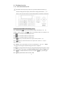
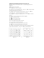
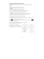
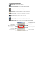
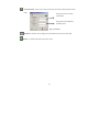
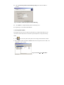
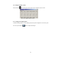
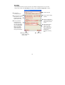
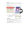
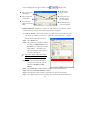
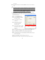
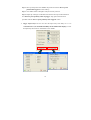
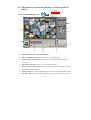
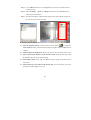
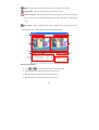
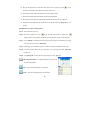
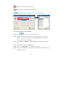
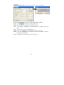
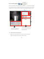
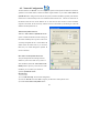
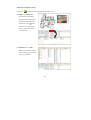
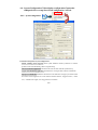
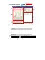
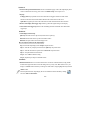
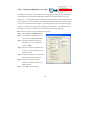
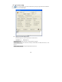
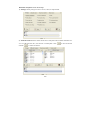
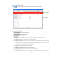
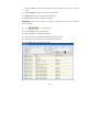
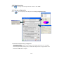
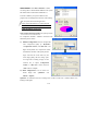
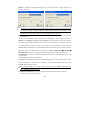
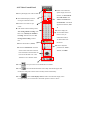
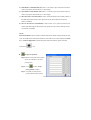
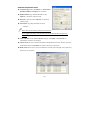
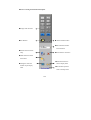
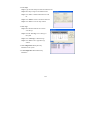
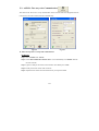
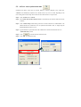
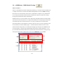
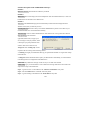
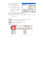
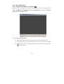
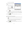
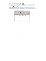
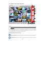
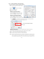
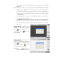
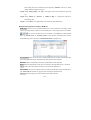
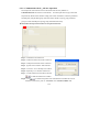
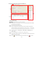
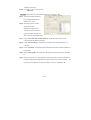
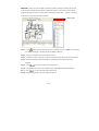
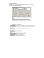
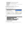
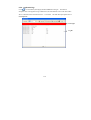
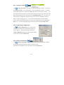
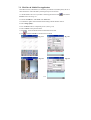
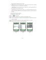
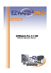
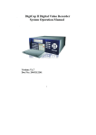
Resize – Resize the video clip.
Decrease frame rate – Decrease the frame rate.
Normal frame rate – Adjust frame rate back to normal.
Increase frame rate – Increase the frame rate.
Screen size can be adjusted by selecting different multiple displays. Click
click
to view videos in 352 x 288; click
view videos in 160 x 120.
to view full screen;
to view videos in 176 x 144; click
to
Smart search video: Mark the objects in a selected region for searching in a recorded video
clips. The events will be listed in the right side window. Please follow the introduction below to
perform this function.
z Function description of the Smart Search:
Sensitivity: Adjust the sensitivity function based on the
selected region size. If it is set as high sensitivity with the
large selected search area, the system may display very tiny
changes on the list, oppositely, if it is set as low sensitivity
with the small search region, nothing might be found as the
result.
Speed: Set the searching speed for the smart search
function, higher degree represents faster speed; oppositely,
lower degree represents slower speed.
Range: Select “One clip”, “All videos”, or “Range” for smart search function. If you select
“Range”, you can set up the video clips range for searching.
Stop to search when object is detected: The system will stop the search process when the
marked object is detected.
z Playback video clips via “Smart search” function:
Step 1. Press
icon on the playback toolbar to display the “Smart search” interface.
Step 2. Press and hold the mouse left button to mark a specific search area.
81
Step 3. Click “Add area” button to save a highlighted region. The user can use the same way
to add more areas.
Step 4. Adjust “Sensitivity”, “Speed”, and “Range” function, and click “Search” button to
start the smart search function.
Step 5. The system will display all detected object change events on the right list window, and
the user can select an event to playback.
z Basic operation of synchronized playback
1.) Select the playback cameras: Click the camera selection button (
) to display the
“Select camera(s)” dialog, select the desired cameras for playback, and click “OK” button to
complete.
2.) Select the split screen display mode: Select a split screen to show all cameras on the screen.
3.) Select a date from the calendar to search the video stream: Select the video stream from
the calendar by the order of year, month and date.
4.) Select display camera: Click “Up” and “Down” button to display the desired cameras’
video stream.
5.) Click a desired gray color video stream block to play: Click a desired gray color video
stream block and click “play” icon to view.
82
4-4-2. Video playback
At the playback screen, you can play back videos. Double click on any video screen to enlarge a
single video. Move the mouse to any video screen to show video tool bar and information of single
video. Double click again to restore the previous viewing screen.
Previous video clip – Jump to the previous video clips.
Next video clip – Jump to the next video clips.
Navigation bar – Display the current position of the video clip and allow
users to move to different points within the clip. Left moves backward, right moves forward.
Mark – Mark a start frame and an end frame of individual video clip.
The user can click “Save” while the playback
video is located at the desire point of Start frame
and click “Goto” to go back the desire point of
83
Start frame. The user can follow the same procedure for setting the desire point of end frame.
After saving the desire point for “Start frame” and “End frame”, the set up record will
automatically send to “Merge file(s)” setup field. The user can set up “Start frame” and “End
frame” for each video clip.
Decrease speed – Decrease the speed of playback.
Normal speed – Adjust the playback speed to normal.
Increase speed – Increase the speed of playback.
Play – Play video.
Pause – Pause video.
Stop – Stop video.
First frame – Jump to the first frame of the selected range of video clips.
Last frame – Jump to the last frame of the selected range of video clips.
Previous frame – Jump to previous frame.
Next frame – Jump to next frame.
Zoom in – Click this icon to zoom in.
Zoom out – Click this icon to zoom out.
Clear zoom – Go back to original video size.
Resize – Resize the video clip.
Snapshot – Capture the video screen and save as a BMP or JPEG file.
Copy video clip – Copy current video clip to a specified location for archiving or distribution.
Delete video clip – Delete the selected video clip.
Synchronize – Synchronize the other playback video channels with the selected video
channel.
84
Repeat – Click to playback video clips in repeat, click once more to cancel repeat.
Audio Volume – Adjust the audio volume of the playback video clips.
Smart search video – Search the playback video clips by marking a specified areas or regions.
Please refer to the 4-4-1 Synchronized playback for the detail description of “Smart search
video”.
Merge file(s) – Merge the different files from the different video clips and export as one
“.AVI” file. Please follow the introduction below to perform this function.
1
2
3
4
5
7
6
8
9
z Function descriptions:
1. Click
&
to switch video clips from the selected time range.
2. Show the detail date and time frame for the selected video clip.
3. Show the start frame of picture from the selected video clip.
4. Show the end frame of picture from the selected video clip.
85
5. Drag the navigation bar to select the certain portion of one video clip or click
to type
the start & end frame to select the desire portion of video clip.
6. Show the time frame and frame number for the selected start frame.
7. Show the time frame and frame number for the selected end frame.
8. Show the list of selected video clips which would like to be merged as one “.AVI” file.
9. Select the location where the user would like to save the file and click “Merge file” to save
the file.
z Follow the steps below to merge the files:
Step 1. Select the desire video clip.
Step 2. Move the navigation bar, click
to type the start & end frame, or simple click
(mark) from the video playback window for selecting the desire portion as the merge file.
Step 3. Click “Add clip” to add the selected video clip into the merge list. To delete the list, simply
click one of the lists and click “Delete clip”.
Step 4. Repeat Step 1 to 3 to add more portions of desire video clips from different video clips.
Step 5. Choose the location where the user would like to save the merge file from “Export file
(.avi)” field.
Step 6. Click “Merge file” to merge the video clips and save as one “.AVI” file.
Video clips information – List the information of all video clips
for search and playback.
Play – Play all selected playback video channels.
Pause – Pause all selected playback video channels.
86
Stop – Stop all selected playback video channels.
Repeat – Repeat all selected playback video channels.
Search video clips – Playback the videos via a single or multi channels.
z Follow the steps below to play back videos:
Step 1. Click
to search for video chips in the database.
Step 2. Select the camera from the drop-down menu. To play multiple videos, select “All
cameras”. If selected all cameras, there will be a “Select cameras” pop-up window for
camera selection after clicking “Search”.
Step 3. Select “All clips”, “scheduling”, or “motion detection” from “search by” drop-down
menu.
Step 4. Select the search method from “Options” field.
Step 5. If you select “All video clips”, click “search” to select cameras.
Step 6. If you select “Time Range”, determine the time frame, and click “search” to find the clips
among the selected time.
87
Delete video clips – Playback the videos from a single or multi channels.
z Follow the steps below to remove a video clip from your archive:
Step 1. Click
on right screen for deleting video chips.
Step 2. Select a single camera or all cameras to delete video chips.
Step 3. Select “All clips”, “scheduling”, or “motion detection” from “search by” drop-down
menu.
Step 4. Select the search method from “Options” field.
Step 5. If you select “All video clips”, click “Delete” to delete the video clips.
Step 6. If you select “Time Range”, determine the time frame, and click “Delete” to delete the
clips among the selected time.
Step 7. Click “OK” to confirm and delete the selected video clips.
88
4-4-3. Text insert playback
The user can playback the videos with text when the DVR integrated with POS system or fingerprint
access controllers. Please refer to the PTI-100 user manual of POS system and FAC-500 user manual
of fingerprint access controller for hardware installation, system configuration and functions usage.
2
1
5
3
4
The text data will be shown here. You
Please refer to the chapter 4-4-1
for detail of toolbar functions
z
can click any text data to display the
video in the left side.
Basic operation of Text insert playback:
Step 1. Select camera which has text over videos from the drop-down menu.
Step 2. Select date from calendar to show all videos in the list.
89
Step 3. Click any video clip to display and playback in the left side. Please note some video
clips might not contain any text data if there is no text transaction in this specified
time.
Step 4. All the transaction text will be shown on “Text record” tab. You can simply click any
text data to display the video from “Text record” tab, search the video clip from
“keyword” tab, or type any words from “Search” tab to search the video clips.
Step 5. You can also un-check “Use default” and click
folders.
90
to search video clips from local
4-4-4. ezBackup
This chapter will show how to back up video clips to another storage device.
z Function description of ezBackup:
Search – Search video files.
Select – Select/Deselect all video clips for back up video clips.
Create backup shortcut – Create shortcut of selected backup videos for the other storage
devices; such as CD-RW/DVD+-RW.
Back up video clips – Back up video clips to Hard Disk.
Setup auto backup schedule – Backup video clips to Hard Disk by schedule
automatically.
CD/DVD Burning – Back up video clips to Hard Disk to CD-RW or DVD+-RW.
About - Press to see the program version.
Exit –Exit the video backup setting window.
z Follow the steps below to back up videos
Step 1. Click
in the top to search for videos in database.
Step 2. Select the camera from the drop-down menu. To play multiple videos, select “All cameras”
Step 3. Select the search method from “Options” field.
Step 4. If you select “All video clips”, click “search” to select cameras.
Step 5. If you select “Time Range”, determine the time frame, and click “search” to find the clips
among the selected time.
91
Step 6. Select video files which you would like to backup by manual. Or you also can click
to “Select all/Deselect all” video files.
Step 7. The ezBackup program provides three methods to backup the video clips and the detail
process are shown as below:
Backup to another HDD by manual:
a. Click
to show “Back up video
clips” window.
b. Check “copy playback program” if you
would like to playback with Witness
playback program. It will back up
“ezPlayback” and “Synchronized
92
playback” program at the same time
c. Select the HDD from “Storage drive“.
d. Click “Start” icon to start backup.
Setup auto backup Schedule:
a. Click
to show “Setup auto backup schedule” window.
b. Select “Enable Auto-backup schedule” function.
c. Select the date to backup video clips from “Backup date from” field.
d. Select “Recycle” or “Stop backup” when backup HDD is full.
e. Select the backup schedule from “Daily“, “Weekly”, “Per hour(s) “, or “Only Previous day”.
f. Select the backup camera (s) and source disk.
g. Select “Target disk” for backup the video clips.
If the “Target disk” is NAS or another PC, please
click “
” icon to display “Map
Network Drive” and follow the dialog instruction
to type the specific path of the network HDD for
backup. To add more Network’s HDD path, please
repeat this step again.
h. Check “First notify to CMS when backup HDD less than” and type for HDD space for
93
warning level and setup the notification method from “Advance”. Please refer to Chapter
3-3-1 (Camera configuration Æ Recording Æ Schedule setup) for detail setup instructions.
i. Set up for “Second notify to CMS when backup HDD less than” if needed.
Backup video clips from DVD+-RW (CD-RW):
a. Click
to show “CD/DVR Burning” window.
b. Insert the backup media such as CD or DVD disk.
c. Select the correct “Device” and “Media type”.
d. Click “Burn now “icon to start backup.
If you enable “Copy playback program “icon, it will
back up “ezPlayback” and “ezSyncplayback”
program at the same time in the CD. You can use the
playback programs to playback the video clips from
CD.
Step 8. Click
to complete backup setup.
94
4-5. Network Configuration
The main function of “ID code” is to solve the possible problem with dynamic IP addresses connection.
@-Witness series DVR contains a built-in IP address register function. If you enable “Auto connect to
dynamic IP server” and type the ID code into the system, its built-in IP Identify capability will allow the
remote users to connect directly to the user’s DVR from their FreeView Pro software or IE browser via
the Internet when the user run the Witness Pro. In cases the user does not have a static IP address
assigned to the DVR, the ID Code may redirect browsers to the DVR by announcing its current IP
address to the IP Dynamic Server.
What is the dynamic IP Server?
When the “Auto connect to dynamic IP Server”
option is enabled, the DVR will send a message to
the central IP Identify Server per hour. This server
will notify and update the user’s current DVR’s IP
address. When the remote users try to access the
DVR, they are routed through the dynamic IP
Server to the DVR.
Do I need to use the dynamic IP Service?
Ask your ISP provider about setting a static IP
address for your local account. Once you have a
static IP address, disable the “Auto connect to IP
identify server” option. If you do not have a static
IP address, you can contact your vendor for
optional “dynamic IP service”.
ID code setup:
1.) Click “ID code setup” from network configuration.
2.) Enter an “ID code” and click “OK” to register your ID code to an IP dynamic server.
3.) Enable “Auto connect to dynamic server”.
95
Video server port: Set up the port number for video streaming remote connections via CMS (FreeView
Pro ). The default port is “1001”.
Event notification port: Set up the port number for pop-up notification to CMS (FreeView Pro
program), the events include Detected motion, Video loss, Sensor triggered, Emergency call, Relay
triggered, Access controller triggered, Storage device fail. Please refer to the DVR setup of FreeView Pro
for event selections. The default port is “5877”.
Select default LAN card: The user can un-check “Select default LAN card” if there is another LAN
card for selection.
Maximum TCP/IP users: Set up the maximum users for connecting DVR via IE browser or CMS
(FreeView Pro )
Connection time limit: Set up the duration time for remote connections to DVR.
(For users that are protected by a Firewall)
If you are encountering either the error message “Cannot locate IP address” or “Cannot identify
server”, please contact the manufacturer of your Firewall and ask them how to create a PORT
MAPPING. This will create a port in your firewall. This Port Mapping will enable the remote user
to access the Witness ASE/HS/RD series Pro from the remote site.
e-Map setup: The user can create an e-Map for the location of DVR, cameras, and other devices and set
up the contact information for notification. When the cameras or other devices on the map are triggered,
the triggered devices will show flash on the map at the same time.
You must entry the DVR no for the CMS auto upload or download the eMap information.
96
z Follow the instructions below for eMap setup:
1.) Click “Information” tab.
2.) Type the information in “Contact person”, “Phone number” “DVR location” and “Note” column.
This information will be shown on the notification to the remote client PC (CMS)when connecting.
3.) Click “e-Map edit” tab.
Device types
4.) Click
and browse the map file from DVR folder and click “Update” icon after the user selects
the Map file. (The map file can be a BMP or JPG file.)
5.) Select the available devices to locate on the eMap from the device tool bar.
6.) Click and drag the device to the suitable location with the left mouse key. Repeat this process for other
devices setup.
7.) Click “
” to “Save & Exit” or “Exit” without saving the settings.
If the user would like to enable notification via flashed icon on the e-Map when motion or alarm is
triggered, you will need to enable “Pop up event notification” as well from “System
Configuration” in Chapter 4-6-1.
If the system supports dual monitor, the eMap will automatically pop up to secondary monitor
(Monitor 02) when Witness Pro launched. The user can also click “
assign eMap to “Monitor 01” or “Monitor 02”.
97
” from screen of eMap to
z Function descriptions of eMap:
Please click “
” from video control panel to bring out eMap screen.
1.) eMap: Click “eMap” tab to
show the floor plan of eMap,
detail information of DVR, and
status of view logs and current
remote users. Click “
” from
cameras to view the pop-up live
video or send the live video to
TV-out monitor.
2.) DVR status: Click “DVR
status” tab to show the real time
status of cameras, relays, sensors,
and access controllers.
98
3.) DVR health: Click “DVR health” tab to check the CPU usage, Network traffic, and HDD
information.
Remote user currently connected The table list the currently remote login user’s information and
discount the currently connected users if you need.
Authorized IP setup The DVR can set up the remote connection for the authorized IP Address only. If
the connection IP Address did not be listed on this window, it will show a pop-up error message “Limit
error” when connection.
Please note that if this function did not be enabled, all the users from any IP address will be able to
remotely connect to the DVR.
99
4-6. System Configuration /Video display configuration/Connection
ezDispatch Server setup/ Save/Load configuration / ezTools
4-6-1. System configuration
z Function descriptions of system configuration:
Enable watchdog reboot triggering If the system shutdown caused by hardware or software
problem, it will reboot DVR and go back to original setting.
Auto-start this DVR application The Witness Pro will auto start when the system starts up.
Logout when minimizing application The Witness Pro will logout when software is minimized.
Pop-up event notification Enable this function the event notification will pop up on monitor when
the selected events happened. The events include “Detected motion”, Triggered sensor”, “Video
loss”, “Unstable video signal”, and “Triggered access controller”.
100
a. Display only the first pop up message Pop up only the first notify message on the screen, if
the triggered events are the same and more than one time.
b. Hide the pop up message after Clear the pop up notify message from the screen after the
setup period.
Stop sound alarm when triggered stop The sound alarm will automatically stop when the trigger
stopped.
Minimize application upon start-up Minimize the window of Witness Pro after it starts up.
Lock Windows hot key Prohibit the users to use Windows hot key.
Save pending live videos before playback The recording video will be saved as a new file when
you click “Playback” icon. You can playback the instant video file without waiting.
Please note it will make your video files with different length from the set video interval.
Enable on-Screen Keyboard Display the On-Screen Keyboard when the user setup the Witness
Pro program.
Enable Live/Capture display toggle icon The toggle switch
icon will be shown on the main
Witness screen. The user can switch “Live display mode” or “Capture mode” by toggle icon.
Execute the video display mode upon Witness Pro launch The user can select the video display
screen “Keep on last display setting”, “Live display mode”, or “Capture display mode” when
Witness Pro is launched.
Asynchronized Main monitor display rotation with Capture display The user can enable this
function to set up different rotation schedule or split video for main monitor (live video display)
and Capture display. This function uses for the application which wants to show difference video
display on two places.
Allow all Windows User Accounts to use this application All users with different Windows
accounts can be allowed to run Witness Pro program.
101
Upon system failure Select PC’s reaction “Restart program” and “Reboot system” from the
drop-down menu when DVR system is abnormal. For example: Select “Restart program”, the
system will automatically restart Witness Pro program when DVR system is abnormal.
Log out when no user interaction is involved for Logout the Witness Pro program when the user
is inactive DVR over the setting duration.
Exit option Select PC status “Exit program”, “Turn off”, “Log off” or “Restart” from the
drop-down menu after exiting Witness Pro program. For example: Select “Turn off”, the system
will automatically shut down after exiting Witness Pro program.
Auto login The DVR will automatically login by saved username and password in Witness Pro
after reboot.
NetCom Module:
1.) Model: Select the type of control board for the PTZ camera, D/I and D/O devices based on the
installed models.
2.) Checksum: It depends on the type of Speed dome camera. Please refer to the manual of Speed
dome camera.
3.) Com Port: You must select “Auto” from the draw menu of “Com Port “icon when you want
to enable the function of Netcom module.
4.) Baud rate: Select a correct Baud rate to control the Speed dome camera or P/T/Z camera from
Witness DVR board (Default setting is 9600 bps).
You must select “9600” baud rate, enable Checksum icon, and select “Pelco P” or “FastCam
V2” or “SDCI-220” when you install I-View’s FastCam III Speed dome camera series.
Enable system periodic auto restart Auto restart or turn off the system at the specific time every
day. Use this function to stabilize the program after a long period of usage.
Enable modem dial-in Enable this function to share one telephone line for both modem and fax.
Otherwise the modem will occupy the phone line always. Select dial up modem model for phone
call notification or 3G modem model for SMS notification from the drop-down menu. Please select
com port from “SMS Com Port” drop-down menu as well.
Please contact your vendor for more information about the model of modem.
102
4-6-2. Video display configuration
1
4
2
5
3
„ Section Descriptions:
Section 1:
¾ Output:
Capture Display: Show 1-32 Ch digital split video on the VGA monitor for recording.
Single TV out: Show 1-32 Ch single video on the TV monitor (Composite video in).
Main Monitor 0: Show 1-16 Ch split-video on the TV monitor (Composite video in).
Spot Monitor 0: Show 1-16 Ch split-video on the TV monitor (Composite video in)
Main Monitor 1: Show 17-32Ch split-video on the TV monitor (Composite video in).
Spot Monitor 1: Show 17-32 Ch split-video on the TV monitor (Composite video in).
1. Main Monitor 0 & 1 videos are also called “Live display mode” when the videos are shown on
the VGA monitor. Please click “
” (toggle switch icon) to select “Live display mode” and
103
“Capture display mode” (each channel will show the time stamp on the video).
2. VGA Monitor 1: Show 1-32 Ch Capture display or 1-16 Ch & 17-32 Ch Live display (Main
Monitor 0 & Main Monitor 1).The user can click“
” icon to select the display mode.
3. VGA monitor 2: Show 17-32 Ch Live display video, IP Camera video, Playback, or eMap
The spilt TV monitor (composite) can show individual display and rotation when
“Asynchronized Main Monitor display rotation with Capture display” is enabled from
“System configuration” tab.
Section 2:
¾ Swap video: The cameras can be switched to different positions for the spilt screen.
¾ Hide video: The cameras can be hided and show the blue screen for the “Live Display Mode” and show
the thief logo for “Capture Display Mode”.
¾ Default: Switch the cameras’ positions back to the factory’s setting
¾ Position display tab: 1-16, 17-32, or 1-32 divisions depend on the different output sources.
¾ Camera number: Represent the number of the camera
Position display
How to swap the cameras for spilt display:
Step 1. Select the output display from “Output”
drop-down menu.
Step 2. Click the camera from Position display tab.
Step 3. Move the mouse and click the camera number
which would like to swap.
Step 4. Repeat Step 2 & 3 to swap other cameras’
positions.
Camera number
Step 5. Click the camera position and check “Hide
video” if needed. Please note if this function is enable, the
background of the grid will become purple.
Step 6. Click “default” to switch back to factory’s
setting if needed.
Step 7. Click “Save” to finish the setting.
104
Section 3:
¾Action to take upon motion detection: The user can enable the pop up video to the output display when
motion is detected. For the setup, please refer to “Schedule setup” from Chapter 4-3-1
¾Pop up:
Full-page video: Pop up the full screen video when motion is triggered. If there are multi motion
detections at the same time, the latest motion detected video will be shown on the screen.
Split video: Pop up the split screen video when there are multi motion detections at the same time.
¾ Restore video display when trigger stop: Enable to go back the original setting of video display.
¾ Clear border when trigger stop: Remove the surrounding red border around the video channel after
trigger stops.
Section 4:
¾ Video display rotation setup:
Split way: Select full screen or split screen (4/6/8/9/10/13/16 spilt way)
Start from: Select which camera or position to start the rotation
Duration: Set up the rotation time for the display screen
How to setup the rotation for the output display:
Step 1. Select the output display from “Output” drop-down menu.
Step 2. Select the way of display for rotation from “Split way” drop-down menu.
Step 3. Select the start camera or position from “Start from” drop-down menu.
Step 4. Set up the duration for rotation time.
Step 5. Click “Add” to finish the setting.
Step 6. Repeat Step 2 to Step 5 to add multi rotation.
Section 5:
¾ Rotation entries list: This is a list of the rotation entries. To edit one of the listed entries, simply double
click the entries appeared in the list. Once the editing is done, you may click “Save” button to save your
changes or “Cancel” button to discard your changes. To delete entries, simply highlight the entry and click
“Delete” button.
After setup the rotation for output display, the user can enable the rotation schedule by clicking
icon from “Video Control Panel”
105
4-6-3. Connection ezDispatch Server setup
The ezDispatch can allocate all the notifications from the following events automatically to the standby
CMS (FreeView Pro ) to dispatch the CMS loading when there are more than 2 CMS server on the
control center. The ezDispatch program will arrange live video to CMS server to balance the loading of
CMS. Such as there are 5 pcs CMS servers for remote monitoring 1000 DVRs, there 13 DVRs send the
Live video to the CSM servers when triggered. The ezDispatch preprogram will average the triggered
videos to 5 pcs CMS servers to get the balance loading for each CMS server. The ezDispatch can be
installed on one of CMS or any kinds of PC stations. Please refer to for ezDispatch setup.
z Follow the steps below to connect ezDispatch Server setup:
Step 1. Check “Connect to ezDispatch server”.
Step 2. Type IP address of ezDispatch server #1
where it has been installed and enabled.
Step 3. Type the port number for connecting
ezDispatch server #1. The default port
number is “5866”.
Step 4. Repeat 2~3 to setup for ezDispatch server
#2, if there is a backup ezDispatch server
installed and enable.
Step 5. Set up the reconnect time to reconnect the
server if the network is disconnected.
Step 6. Select the event types for sending
notification to CMS (FreeView Pro ) via
ezDispatch server.
Step 7. Click “OK” to save the setting.
106
4-6-4. Save / Load Configuration
It might be annoyed to repeat all steps for the system configuration if the user has to install several DVRs
at one time. Therefore, the user can click “Save” to backup the configuration setting as “.set” file in local
disk and click “Load” to restore the backup configuration setting from local disk or other DVR.
4-6-5. ezTools
This window is to provide the selection of DVR main program tools without minimize the current
surveillance sever program. For the detail functions, please refer to Chapter 5.
107
4-7. User assess setup
Click
icon to create usernames, passwords, and the user’s privilege to login Witness Pro in different
access levels from “User assess setup”.
z
Supervisor username and password
The default supervisor name and password are listed as below:
Username: root
Password: 123
Enable DVR access: Allow the user to access Witness Pro program.
Enable Remote access: Allow the user to remotely connect DVR via CMS (FreeView Pro ) or IE
browser
Enable validate duration: Set up the usage duration for the user.
108
z Function descriptions of User access setup:
1.) Privileges: Select privileges for users to access, control, or setup for DVR.
2.) Authorized cameras: Select cameras for the users to setup and control in Witness and remote live
view via CMS (FreeView Pro ) or IE browser or mobile phone. Click “
and click “
” to remove all cameras.
109
” to select all cameras
3.) Remote access schedule: Enable and setup the remote access schedules for the users to limit the
remote access period if needed. Select “Daily”, “Weekly”, and “Special Duration” for the access
schedule.
4.) Remote control: Set up the maximum bandwidth and connection time to allocate and control the
bandwidth of network where the DVR located and select the authorized cameras for remote listen if
needed.
110
z Please follow the steps below to modify the supervisor’s name and password:
Step 1. Type new supervisor name and password.
Step 2. Press “Select all” (only for supervisor) for the privileges.
Step 3. Click “Save” to add the user in the list.
Please remember removing the default supervisor “root”, otherwise there will be two supervisors.
z Set privilege for additional users
Step 1. Type username and password.
Step 2. Select privileges.
Step 3. Click “Authorized cameras” tab to select the cameras for remote live view. The user can
click “
” to select all cameras and click “
” to remove all cameras.
Step 4. Click “Remote access schedule” tab to set up the connection schedule if required.
Step 5. Click “Remote control” to set up maximum bandwidth and connection time limit, and select
cameras for remote listen if required.
Step 6. To create other users, please repeat step 1 to 5.
Step 7. Click “
” to search the username which has
been created. Type the username from “Search for”
field and check “Go Top” if the user would like to
search the list from the beginning of the username
list.
1. If the supervisor’s password or username is lost, Witness ASE/HS/RD series must be reinstalled.
All previous settings will be lost. However, saved videos will not be erased.
2. Password must consist of 0-9 and a-z or A-Z.
3. The password is case sensitive. (PaSsWoRd is not the same as password)
4. Please remember to click “
” after set up from each tab.
z Remove/modify user privileges
Step 1. Select the user in the username list. Click “Delete” to remove user or double-click on the
username to modify user privileges.
111
4-8. Application logs
Click “
” icon to check the system logs by the date and different events types.
Event types
Log list
z Function Description:
Save log button: Save the log list as a file.
Clear log button: Clear current log list.
Exit button: Exit this interface.
Event types: User can simply click each type tabs to find a specific event’s log list easily.
1.) Logging in/out: Show the status of user’s login and log out.
2.) Detected motion: Show the status detected motion if the user enabled “Motion triggered
recording” (Camera configuration Æ Recording Æ Schedule setup). The user can double click
the event to view the video when motion is triggered.
3.) Video loss: Show the status of the video signals.
4.) Remote access: Show the status of remote connection.
5.) Hard disk fail: Show the status of the health condition of HDD.
6.) Trigger output relays: Show the status of relays if any event is triggered. If the user set up the
112
recording schedule when relays are triggered, the user can double click the event to view the
video.
7.) Access controller: Show the access status and information.
8.) Operation: Show the record of operation modification.
9.) System: Show the status of Witness Pro program.
Search logs: Search the logs via time, date, log type, or simply type the keywords of events and
devices for search.
1.) Click “
” for to search the logs.
2.) Select the duration time for searching logs.
3.) Select “Log type” from the drop-down menu.
4.) Type any keywords in “event” and “device” field for quick search.
5.) Click “Save” if you would like to save the searched logs as a file.
6.) Click “Exit” to leave the search logs window.
113
4-9. Peripherals setup
Click “
” icon to set up I/O configuration and parameters from “Peripherals setup”.
F
a
b
c
d
e
f
If the NC-3213USB NetCom module has been installed, all functions icons can be enabled.
Otherwise only “Emergency notification setup” and “Finger-key access control setup”
can be enabled. The user can check if the NC-3213USB NetCom module installed properly
by this function.
a.) NetCom output repays setup (Optional)
While NC-3213USB is installed in the DVR system,
you can click “NetCom output relays setup”
Function Description:
„ Control: Select the device for setup.
„ No/Name:
Type
“Controller
name”
corresponding to the desired relay number.
„ Duration: Type the controller’s working period
when relay is triggered.
114
„ OK: Click “OK” to accept setting.
„ Copy: Copy the parameter setting to other relays.
„ Cancel: Click “Cancel” to discard changes in parameter.
b.) NetCom output replays on/off & d.) NetCom TT module control (Optional)
This function is to test remote controlling. Please click the “NetCom output replays on/off”
and “NetCom TT module control” for setup.
c.) NetCom sensor inputs setup (Optional)
Step 1. Select sensor from the
drop-down menu and type location
for the sensor from “Location”
field.
Step 2. Select sensor type (NC or
NO) from “Type” drop-down menu.
Step 3. Check “Enable sensor” and
click “
” to set up schedule. Please note if you did not set up schedule, the sensor
will be enabled in 24 hours.
Step 4. Select the following actions to take when sensor is triggered.
115
„ Display full-page video: Select the camera to display as full page video when sensor is
triggered.
„ Enable recording: Select the camera you want to record when sensor is triggered.
„ Enable Snapshot: Select camera for snapshot when sensor is triggered.
„ Enable sound alarm: Set up sound alarm when sensor is triggered.
„ Enable notification: Select the types of notification when sensor is triggered.
„ Shift PTZ position: Set up the PTZ camera shift position when sensor is triggered.
„ Enable TV out: Set up the camera for TV out when sensor is triggered.
Step 5. Select the output relays from Relay 01 to 06 in “Controller board” (NC-3213USB) or
select the output relays from each NC-180AZ PTZ receiver module.
Step 6. Type the recording duration after sensor is triggered from “Post recording” field.
Step 7. Click “OK” to complete the setting.
e.) Emergency notification setup
The user can set up emergency notification when the panic button is pushed. Please follow the
same procedure with “NetCom sensor inputs setup” to configure the emergency call features for
actions to take when triggered.
f.) Access controller setup (Optional)
Step 1. Select a Fingerprint device
from the drop-down menu and type
location in “Location” field.
Step 2. Check “Enable Sensor” and
click “
” to set up
schedule. Please note if you did not set
up schedule, the access controller will
be enabled in 24 hours.
Step 3. Select trigger type “Trigger”, “Verify fail”, “Verify OK”, “Disconnect” or “Door open”
from the drop-down menu.
116
Step 4. Select the following actions to take when sensor is triggered.
„ Enable recording: Select camera you want to record when action is taken.
„ Enable Snapshot: Select camera to snapshot when action is taken.
„ Enable sound alarm: Select camera for snapshot when action is taken.
„ Enable notification: Select the types of notification when action is taken.
„ Shift PTZ position: Set up the PTZ camera shift position when action is taken.
„ Enable TV out: Set up the camera for TV out when action is taken.
Step 5. Select the output relays from Relay 01 to 06 in “Controller board” (NC-3213USB) or
select the output relays from each NC-180AZ PTZ receiver module.
Step 6. Type the recording duration after sensor is triggered from “Post recording” field.
Step 7. Click “OK” to complete the setting.
The user can go to the path “Windows Æ Start Æ Programs Æ Witness XXXX Pro” and
simply click “Access control –ezFingerkey” for detail management and setup. Please refer
to the fingerprint access controller user‘s manual.
117
4-10. Stop alarm siren
Click “
” icon to stop alarm and adjust the audio volume or check “Mute”.
4-11. Storage configuration
Click “
” icon to set up storage and Compression from “Storage configuration setup”.
z Function description of Storage configuration:
Storage devices setup: Enable the system configured video storage device (Drive “C:” is the flash
card for saving the DVR operating system). To enable the configured device, simply check the device
and click the “OK” button to complete.
118
Renew database: Click “Renew database” to detect
new storage device and rebuild the database in the system.
This button must be clicked after a HDD drive is
removed or added to your system. Otherwise, the
program may not find playback video files. After clicking
“OK”, the system will restart the application.
Please perform this function if you find playback
function work abnormal. Running this function will
rebuilt the Database of video clips.
Video compression image quality: The system provides
two compression methods – MPEG 4 and H.264. The
detail description as below:
a.) MPEG 4 configuration: The user can adjust the
video compression quality by “Keyframe”,
“Compression control”, and “Data rate”. The
higher the keyframe rate, compression control,
and Data rate, the better video quality, but the
larger video file size. In the same way, the
lower image quality, the more storage space
for longer time recording. Simply use the
selection bar to adjust “Compression
control” or “Data rate” section and click
“OK” button to complete.
b.) H.264 configuration: You can select two
modes
Single
Pass
“Quantizer”
and
“Bitrate”. (Option)
Quantizer: It’s suitable for the lower exchange rate of video. The file size is smaller, but the CPU
loading will be higher.
119
Bitrate: It’s suitable for the higher exchange rate of video. The file size is bigger, but the CPU
loading will be lower.
We strongly recommend using Intel Q6700 or better CPU when you use the H.264 compressor
for continue recording. The H.264 compressor requests more powerful CPU. Therefore, we also
suggest the user to reduce the recording rate when using the H.264 compressor.
Recording setup: When the user enables “Record live video feeds to hard disk”, the video clips
will be saved to hard disk at the set duration time automatically. For example, if you set “5
minutes” for “Frequency of auto-save every” field, the video clips will be saved every 5 minutes.
It’s better to type the duration time between 5 and 30 minutes. This function can minimize video clip
loss under abnormal conditions, such as a power outage. It is recommended to add a fan for the
additional heat in the hard disk. If you disable this function, the video clips will be saved in memory
temporarily and saved to disk based on your settings in “Camera configuration Æ Recording Æ
Recording file size”. However, if the system shuts down abnormally, all video clips will be lost.
Low disk space: It will start to free space on the hard disk when only a certain amount of space is left
on your hard disk. Older files are erased first.
a.) Space to erase at once: This specifies the amount of disk space to erase when the above limit is
reached. Older files are erased first. For example, if you type 1200 MB, the system will erase
1200MB when the limit is reached.
Please setup 9999 MB Space to erase at once when you use the CP-4800DX DVR Card, it can
reduce the HDDs deleted files always.
b.) Limited recording day(s): The system will start to delete the oldest video clips when the
recorded videos are over the set period.
120
4-12. Video Control Panel
„ Enable screen rotation for
capture display and TV-out
„ Set up the display time clock for DVR
monitors, or “Show IPCam
on second monitor” and
„ Select different display mode for
“Show 17-32 cameras on
viewing all connected cameras.
second monitor” if the DVR
„ Switch to next camera or split
supports dual monitor. (Note
screen
A)
„ The channel selection buttons present
“live viewing without recording” with
„ Click to display the
camera number button
black color, “Stand by for scheduled
from 33~64 if you
recording” with blue color, and “live
installed the model of
viewing with recording” with red
32 channel DVR with
color.
IP cameras.
„ PTZ control buttons. (Note B)
„ Click to adjust the
„ Click the “black button” and select
a PTZ camera. If the PTZ camera has
parameters for “Focus”,
“Zoom”, and “IRIS”
been selected, the camera number will
be shown on the black circle. Click
“Arrows” to move the PTZ camera.
„ Click
to set up I/O sensor of NC-080AZ Receiver module.
„ Click
to show the DVR information on the e-Map. If the DVR supports dual
monitor, the e-Map will be shown on the secondary monitor automatically.
„ Click
to show “Video display control”121
window and control the display videos
for Capture display or TV-Out monitors. The detail operation is shown as below:
Select output screen
Select video split
way to show on
the output screen
Click “prev.”,
“Next”, or “Number
Click to enable the
tab” to show a single
rotation schedule for
video on the output
output screen if
screen
needed
Click to clear the pop up video from
the output screen when motion(s) is
triggered.
Note A:
1.) Capture Display Video Rotation (On): Show 1-32 Ch digital full or split screen rotation on
the VGA monitor.
2.) Single TV Out Video Rotation (On): Show 1-32 Ch single video rotation on the TV
(Composite)
3.) Main Monitor 0 Video Rotation (On): Show 1-16 Ch full or split screen rotation on the TV
monitor (Composite) or VGA monitor (Live video display).
4.) Spot Monitor 0 Video Rotation (On): Show 1-16 Ch full or split screen rotation on the TV
monitor (Composite) VGA monitor (Live video display).
122
5.) Main Monitor 1 Video Rotation (On): Show 17-32 Ch full or split screen rotation on the TV
monitor (Composite) VGA monitor (Live video display)
6.) Spot Monitor 1 Video Rotation (On): Show 17-32 Ch full or split screen rotation on the TV
monitor (Composite) VGA monitor (Live video display).
7.) ) Show IP Camera on second monitor: Click to switch IP cameras to the secondary monitor if
the DVR supports dual monitor. (This option will only be shown when the second VGA
monitor is installed)
8.) Show 17-32 cameras on second monitor: Click to switch “17-32” split screen to the second
monitor if the DVR supports dual monitor. (This option will only be shown when the second
VGA monitor is installed)
Note B:
PTZ control buttons: The user needs to install the PTZ camera and the controller board (NC-485
or NC-3213USB) first for PTZ cameras functions. Please make sure to set PTZ ID from “General”
tab in “Camera configuration”. Before setting from PTZ control buttons, please select PTZ
camera from “
z
” icon.
Set up preset positions:
Step 1. Move the PTZ camera to the position
where you would like to set up for
preset position.
Step 2. Click “
” to show “Set up
preset positions” window.
Step 3. Click “Set” to set the current
position of PTZ camera as preset
123
position.
Step 4. Type the location for the preset position.
Step 5. Click “Goto” to test if the PTZ camera aims to the present position.
Step 6. Click “Exit” and repeat Step 1 to 4 for other preset point setup.
z
Set up motor speed: Move the navigation bar to adjust
the speed of “PAN”, “TILT”, and “ZOOM” for PTZ camera.
z
Set up swivel: This “Set up swivel” interface is for “FastCam III (V2)” only. The
different PTZ cameras will have different Graphic User Interface (GUI). Please refer to the PTZ
camera user’s manual for detail information.
1.) OSD: Click to show PTZ camera’s “on screen display (OSD)” menu. Click “arrow” and
“Open” for OSD setup.
2.) Aux: Trigger reset signal to PTZ camera.
3.) Auto scan:
Step 1. Move the PTZ camera to the position for “Left preset” and click “Set” to save the
current position.
Step 2. Move the PTZ camera to the position for “Right preset” and click “Set” to save the
current position.
Step 3. Click “Go” to test if the PTZ camera aim to the present position.
124
Step 4. Click “Auto scan” to move the PTZ camera between “Left preset” and “Right preset”
automatically.
Step 5. Click “Stop scan” to stop auto scan function.
4.) Preset scan: Click to move the PTZ camera for preset positions which have been set up from
“Set up preset positions” and click “Stop scan” to stop preset scan function.
5.) Exit: Click “Exit” to leave “Set up swivel” window.
125
Chapter 5. ezTools
This chapter will discuss the DVR’s accessories programs and set up for each function.
5-1. ezWebServer - IE Browse Server
This function is to provide user for remote monitoring with IE browser via Internet.
z Setup in local host DVR sever:
Step 1. Click “ezWebserver” from “ezTools”.
Step 2. Check “Enable auto run system” to auto run ezWebServer when start the Witness Pro
system every time.
Step 3. Click “Set up ezWebServer” and fill out the DVR’s IP address for “Web IP address”
section. For detail about the static IP address, please contact your ISP provider. Please note
if you like to connect the DVR through both “Internet” and “LAN”, do not fill this
section.
Step 4. Click “Web File”, fill out the information in each section of “Demo.htm” interface, and
click “Generator” to complete the settings.
126
“Demo.htm” Setup interface section:
„ Connection Type: Select “IP Address” or “ID Code (For
Dynamic IP address connection)” for connection.
„ DVR IP Address: Type the DVR IP address if “IP
Address” is selected for connection type.
„ ID Code: Type the ID code if “ID Code” is selected for
connection type.
„ Port number: Type the port number for remote
connection.
Please make sure the setting connection port is not used
by PC program commonly, or the connection may be collided with other PC application
program.
„ Auto connection: Check “Auto connection” and type “Username” and “Password” for
automatically connection via remote PC.
„ Add site book: Save the connection information to this DVR in the site book. The users can select
the DVR from the list of “Site Menu” for remote connection via IE browser.
„ DVR version: There are two versions of Witness Pro currently. Select the right version of the user’s
Witness Pro for connection.
127
Remote client PC setup:
Step 1. Click IE Browse from the remote client’s PC. Type the IP address of DVR Server.
Step 2. Please allow the ActiveX program to be installed on the PC when the ActiveX pop-up.
Step 3. You can select the DVR list from “Site Menu” drop-down menu for remote connection.
Step 4. Click “
” icon from the left side
control panel to connect the DVR
Server and display the “Connect to
local site” interface.
Step 5. Create a name in “Site name”, type
DVR IP address or ID code, (TCP/IP)
port number, User name and Password,
and click “Connect” to start the
connection.
128
z Browser Viewing Tools Function Description:
„Display mode selections
„Sites Rotation
„ Channel selection button.
„Select the DVR from the
list of Site Book.
„Remote DVR connection
„ Disconnect the connection.
setup.
„Enable audio and control
PTZ camera.
„Switch the channels in
„Enlarge the connected
full size display mode.
channels in split display
„See the detail operation
mode
from on line help menu.
129
5-2. ezRServer - Remote Control Server
The function of ezRserver program of Witness Pro is to allow full access DVR for remote technical
assistance, or to remotely setup the DVR’s configuration. The remote client must use “ezRClient” in
“FreeView Pro ” to make the connection between the remote PC and the DVR.
z Follow the steps below to setup ezRServer:
ezRserver program on DVR site
Step 1. Click “ezRServer” from “ezTools”.
Step 2. Enable “Autorun ezRServer” to
automatically run “ezRSever” when the
system starts.
Step 3. Set the TCP/IP port for remote client PC
connection. The default port is “1901”
Step 4. Set the connection password.
Step 5. Set “Setup password” for login for configure the ezRserver program.
Step 6. Click “OK” to enable the ezRSever function and complete the setting.
¾ Disconnect all clients button: Disconnect all remote connections.
¾ Exit button: Disable the ezRSever function and exit without the setting.
¾ Proxy server: Enable “Proxy server” if the user does not know how to open the firewall port
from PC or router for remote connection. Please follow the steps shown as below for setup:
Step 1. Click “
” icon to pop up the setup window.
Enable “Run ezProxyClient when windows
starts” to automatically run “ezProxyClient”
when windows starts.
Step 2. Enable “Auto connect when ezProxyClient
starts” to automatically connect to ezProxy
Server when ezProxyClient starts.
Step 3. Type the IP address of Proxy Server DNS; this IP
130
address must be math the IP address of PC which is installed ezProxyClient program.
Step 4. Type the port for connecting ezProxy Server. The default port is “1288”.
Step 5. Click “Connect” to connect ezProxy Server.
ezClient program on Remote Client PC site
Step 1. Type DVR’s name in “Site name”
field.
Step 2. Type IP address of the user’s DVR.
Step 3. Type the TCP/IP port to connect the
user’s DVR. The default port is
“1901”.
Step 4. Type the connection password which
has been set from ezRServer.
Step 5. Check “View Only” if the user
would like to view the DVR’s screen
without any interruption.
Step 6. Click “Add” to save the connection
information of this DVR in the list.
The user can simply click the DVR’s name from the list for connection without typing the
information again.
Step 7. Click “Copy” to copy the connection information of DVR from the site book of FreeView
Pro .
Step 8. Click “Remove” to delete the connection information of the DVR from the list.
Step 9. Select DVR name for the list and click “Connect” to connect DVR or click “Exit” to leave
the program.
131
¾ User setup:
Step 1. Type user name and password for the authorize user.
Step 2. Select the privileges for the authorized user.
Step 3. Click “Save” to add the authorized user in the
list.
Step 4. Click “Delete” to remove the user from the list.
Step 5. Click “Exit” to leave the setup window.
¾ View Logs:
Step 1. Select the date which the user wants to
view the logs.
Step 2. Click the “Save logs” to save the logs in
the system.
Step 3. Click “Clear logs” to delete the logs.
Step 4. Click “Exit” to leave application logs
window.
¾ Save configuration: Backup the setup
information in the system.
¾ Load configuration: Reload the backup
information.
132
5-3. ezSTalk - Two-way voice Communication
This function will show how to set up communication of the real-time audio from designated locations
(camera site) to the control center (DVR site) simultaneously.
Fig 4-8.1
Fig 4-8.2
z Follow the steps below to setup audio communication:
On DVR site
Step 1. Click “ezSTalk” from “ezTools”.
Step 2. Check “Run ezSTalk when windows starts” icon to automatically run “ezSTalk” when the
user turn on the PC.
Step 3. Type the TCP/IP port for remote client connection. The default port is “1701”.
Step 4. Set the password for remote client connection.
Step 5. Adjust the audio volume for listen and talk to suit your request if needed.
133
On Remote Client PC site
Step 1. Go to the path of Windows “Start” menu Æ “Programs” Æ “FreeView Pro ” click
“Two-way voice communication – ezCTalk”
Step 2. Type DVR’s “IP address” or “ID Code”.
Step 3: Type “Password” and “TCP/IP Port” which must be matched with the setting in “zzSTalk”
of Witness Pro.
Step 4. Select “Audio sample rate”. It will have a better audio quality with 16K audio rate, but
occupy higher bandwidth. Oppositely, it will only have a normal audio quality with 8K audio
rate, but less bandwidth.
Step 5. Check the “Talk” and “Listen” function for “Two-way voice communication”.
Step 6. Adjust the audio volume of “Listen” and “Talk” to suit the user’s request if needed.
Step 7. Press “Connect” to start the communication process.
134
5-4. ezReboot - Auto-restart the DVR machine
It is recommended the user to enable “System reboot schedule” function of the Witness Pro
application to routinely (such as weekly or before important events) refresh the DVR system to its
original state. Please follow the instructions below to complete this configuration.
Step 1. Click “ezReboot” from “ezTools”
Step 2. Check both “Run ezReboot when Windows starts” and “Enable system restart schedule”.
Function Description:
a.) Run ezReboot when Windows starts: Automatically launch “ezReboot” program in the
background with an icon on the system tray.
b.) Enable system restart schedule: Enable your preset reboot schedule activity.
Step 3. Click “System Restart Schedule Setup” to set up the system reboot schedule.
Step 4. Select the appropriate schedule timeframe by checking “Every day”, “Every week” or
“Special period”.
Step 5. Type the restart time and other available schedule info, and press the “Add” button.
Step 6. You can set up several reboot schedule entries for the DVR machine. After adding the schedule
entries, press “Exit” button to return to the previous [ezReboot] window, and press “OK”
button to activate the auto-reboot function. This icon “
” will automatically appear in the
Windows system tray located at the bottom right of your screen.
135
5-5. ezClock - Auto-synchronized time
Sometimes the DVR’s clock time can become behind or forward compared to the actual time.
“ezClock” will automatically adjust the user’s DVR’s clock every once in a while, depending on the
user’s setting in the ezClock setup. This section will show the user how to set up ezClock.
Step 1. Click “ezClock” from “ezTools”
Step 2. Check “Run ezClcok when windows starts” to automatically run ezClock when the user turn
on the PC.
Step 3. Click “ezClock Setup“ button and type the user’s favorite Time Server’s DNS address or IP
address that the user would like to use to synchronize the DVR’s clock, or simply keep the
default Standard Time Server as it is.
Step 4. Type the duration to synchronize the clock of Witness Pro with the selected Time Server in
“Synchronize Every” field.
Step 5. Click “
” to test the local time and Server time.
Step 6. Click “OK” to complete the setup.
136
5-6. ezHDDSmart - HDD Health Checkup
What is S.M.A.R.T.?
S.M.A.R.T. (Self-Monitoring Analysis and Reporting Technology) is an interface between the BIOS and
a computer’s hard disk. It is a feature of the Enhanced Integrated Drive Electronics (EIDE) technology
that controls access to the hard drive. If S.M.A.R.T is enabled when a computer is set up, the BIOS can
receive analytical information from the hard drive and determine whether to send the user a warning
message about possible future failure of the hard drive.
SMART monitors a set of drive attributes, such as temperature, throughput performance and the number
of hours the drive has been powered on. It compares these attributes to a corresponding set of thresholds.
If an attribute drops below its threshold, the drive is no longer considered fit for use and should be
replaced immediately. Not all attributes are available on all drives, however. It is the responsibility of the
drive manufacturer to include SMART support. Sometimes the DVR’s HDD will crash or cannot
read/write the data unexpectedly. To avoid this problem happen again and again, our ezHDDSmart will
provide the directly or indirectly affect hard disk health status and give statistical information. It can
provide the hard disk reliability and the failure prediction function and send the user a warning message
about possible future failure of the hard drive. Please click “ezHDDSmart” from “ezTools”
2
1
3
4
5
137
Function description of the “HDD Health Checkup”:
Section 1:
HDD Information: Hard disk drives installed in your DVR.
Section 2:
HDD status: This section displays the current temperature of the selected hard disk drive, as well as its
health status level and surface sector defect factor.
Section 3:
Auto start: This ezHDDSmart program will automatically launch itself in the background when
Windows starts (when you turn ON your PC).
Checkup interval: Decide how often you would like ezHDDSmart to perform a scan check of your
installed hard disk drives to determine their reliability.
Auto-save logs: It will record the attributed factors of the defect on the view log table when checked.
Pop-up message: The main DVR
application (Witness Pro) will pop up an
error message to notify any failures, which
could require your prompt attention when
checked. There are two failure levels,
“dangerous” and “warning only”. Please
respond to the error message in the following manner:
** Warning: It is highly recommended to back up your problematic hard disk on a regular basis to help
reduce data loss.
** Dangerous: Failure Predicted! Please replace your hard disk drive immediately, or at least disable it
in the Storage Devices Configuration within Witness Pro.
Send e-mail: Any HDD error messages will be sent to you via email when checked.
E-mail setup: Type your email address to receive HDD error message notifications. Please follow the
steps below to set up email notification:
Step 1. Type the receiver’s e-mail address in the “Add new e-mail address” entry field.
Step 2. Fill both “SMTP server” and “Port” in the entry fields.
Step 3. Type the sending e-mail address in the “From address” entry field.
138
Step 4. Check “Authenticated login” box.
Step 5. Fill both “Username” and
“Password” in the entry fields.
Step 6. Click the “Add” button to save the
user’s profile into the e-mail list on the
left pane. The user can click “Delete”
button to remove an e-mail profiles
from the list.
Step 7. Repeat step 1 through 6 to add another e-mail profile.
Step 8. Click the “Send test e-mail” button to test the user’s settings.
Step 9. Click “Save” button to keep the user’s new e-mail profiles. This will automatically exit the
“e-mail settings” window.
Section 4:
View Log: Click to enter a previous date to recall health status and detail report of HDD.
Detail: Click to go back to the detail status information column.
Minimize: Minimize the ezHDDSmart program into the system tray.
Save log: Save the health status reports in the disk.
Exit: Close this application program.
139
5-7. ezUPSCheck
If the user installed the UPS with DVR for power management purpose, the user can set up the actions to take
for DVR when there is not enough power capacity for UPS or when the electricity is come back to the DVR.
Please follow the steps below for setup.
Step 1. Click “ezUPSCheck” from “ezTools”
Step 2. Check “Enable auto run system” to
automatically run “ezUPSCheck” when you
turn on the PC.
Step 3. Check the UPS status. If the UPS is well connected to DVR, the status of UPS will be automatically
shown on “ezUPSCheck” window.
Step 4. Click “Set up ezUPSCheck” for function selection.
Step 5. Auto exit Witness Pro program when UPS power is less than: The system will auto save the
current video and exit Witness Pro when the UPS power is less than the set percentage.
140
Step 6. Auto run Witness Pro program when power comes again: The system will auto start Witness Pro
when the power comes back. Click
to locate “Witness Pro” from “Source” field.
Step 7. Click “View logs” to view the status of “ezUPSCheck”.
Step 8. Click “OK” to leave the setup window.
5-8. ezMobileServer – MobileView Server
This function will show how to set up remote viewing the cameras in DVR via mobile phone. For the
detail setup and operation, please refer to “ezMobileServer Application” in Chapter 7-3.
141
5-9. Other Applications
5-9-1. Single-file video playback – ezPlayback
This function is for user to play back video clips in fast and simple way. Please go to the path: Windows
“Start” menu Æ “Programs” Æ Witness (series AS/ASE/HS/RD) Pro, and click the “Single-File
Video Playback – ezPlayback” selection.
z
To open a video clips and play:
1.) Press the “file” function from the program upper left side, and click “Open” selection.
2.) The program will display a file selection dialog, select a video clips file, and press the “OK”.
3.) The program main screen will display an initial image of the selected video clip, simply press
“
” to start the playing.
142
ezPlayback Control Panel Function Description:
Play – Play back videos.
Pause – Click this icon once to pause videos.
Stop – Stop videos.
Previous frame – Jump to previous frame.
Next frame – Jump to next frame.
First frame – Jump to the first frame of video clip.
Last frame – Jump to the last frame of video clip.
Zoom in – Click this icon to zoom in.
Zoom out – Click this icon to zoom out.
Original – Go back original video size.
Navigation bar – This displays the current position of the video clip and allows users to
move to different points within the clip. Left moves backward, right moves forward.
Snapshot – Capture the video screen and saved as a BMP or JPEG file.
Resize – Click this icon to resize clip.
Decrease frame rate – Decrease the frame rate.
Normal frame rate – Adjust frame rate back to normal.
Increase frame rate – Increase the frame rate.
Smart search video: Mark the objects in a selected region for searching in a recorded video
clips. The events will be listed in the right side window. Please follow the introduction below to
perform this function. Please refer to Chapter 3-4-1 for detail function description.
143
5-9-2. Multi-file video playback – ezLANPlayback
This section introduces how to use the ezLANPlayback program via the LAN connection. Before start
to use ezLANPlayback program, please make sure that the file folder (e.g. ClipPro folder) of the
Witness Pro is shared to network user. Please go to the path: Windows “Start” menu Æ “Programs”
Æ Witness (series AS/ASE/HS/RD) Pro Æ“Multi-file Video Playback – ezLANnPlayback”
selection.
z Play video clips from a default folder:
Step 1. Use default local video clips file folder,
simply click the “
” icon on the
right side control panel, display a video
clips searching dialog.
Step 2. Select the desired camera specific date
and time, and click the “Search” button
to search the video clips.
Step 3. The system will automatically playback if the program finds the video clips, or it will
144
display a message of “No Video Clips”.
z Play video clips from the local specific
folders:
Step 4. Select a specific local folder of the
video clips, simply uncheck the “Use
default” box, press the
icon on
the right side control panel, and the
system will display the “Search video
clips” dialog.
Step 5. Click the
icon to select a specific video clips folder for playback, and press the
“Add” button to save the selected folder path for video clips searching list, and repeat this
step to add more video clips folder path on the searching list. Press the “Re-search video
clips” button to finish the adding.
Step 6. Click the “
” icon and repeat the Step3 and Step4 above again to play the specific
local folder video clips.
z Play video clips from the network sharing folders:
Step 1. To play the video clips from the remote network sharing hard drive folder, please click the
“
” icon to display the network hard drive setting dialog, follow the dialog instruction
and type the specific directory of the network sharing folder to add the path in the
searching list. To add more network sharing folder, please repeat this step again. Press the
“Re-search video clips” button to finish the adding
Step 2. Click the “
” icon and repeat the Step3 and Step4 above again to play the network
sharing folder video clips.
145
5-9-3. Access Control – ezFingerKey
While the DVR integrate with the fingerprint access controller, user can go to the path of Windows
“Start” menu Æ “Programs” Æ Witness (series AS/ASE//HS/RD) Pro, and click the “Access
Control – ezFingerKey”. Please refer to the fingerprint access controller user manual for detail
information about the fingerprint access controller installation, system configuration and the functions
usage.
146
Chapter 6. Remote Client PC Software
6-1. Start Using FreeView Pro (Remote Client Program)
Once you have finished installing the software, please go to the path: “Start” menu Æ “Programs”
Æ “FreeView Pro ” Æ “Remote viewer – FreeView Pro ”
z Remote Viewer - FreeView Pro : The user can remotely patrol the DVR from any place at any
time as long as you have the access to an “Internet”.
z Uninstall FreeView Pro : Remove FreeView Pro from your computer.
z Two-way voice Communication- ezCtalk: Real-time audio from designated locations are
simultaneously transmitted to both the control center and designated DVR sites. Please refer to
the chapter 4-3 for the detail setting.
z Remote Control- ezClient: The Remote client can set up the DVR from remote site. Please
refer to the Chapter 4-2 for the detail setting.
z ezDispatch - ezDispatchServer: The user
can assign any CMS (FreeView Pro ) as the
ezDispatchServer to arrange live videos or
notification events to CMS server and
balance the loading of CMS.
147
6-2. Remote Client Program Operation
1
2
3
4
5
6
7
8
10
9
Many of the functions in FreeView Pro behave similarly or even identically to those of Witness
Pro software.
The tool menu bar enables the user to use TCP/IP to connect to the DVR Server via Internet or Intranet
easily, control the video channels of the DVR Server, display DVR Server video channels, save video
files, and configure exactly how you want the program to work.
Function descriptions of tool bar panel
Connect to local site: Connection to the DVR Server for remote view, playback or download.
Communication book: Set up remote users, DVR’s connection, and Group’s connection
148
information to remote access to DVRs, edit e-Map, and set up event notification for fully
monitoring the DVRs.
Play back video clips: Search video clips by DVR site name and play back one or more saved
video files in the remote client’s PC.
System Configuration: Configure the CMS main general settings. There are three categories
including “System configuration”, “Connection ezDispatch Server setup”, and “Save / Load
configuration”.
User access setup: Manage a list of users with different access privileges for CMS.
Application logs: Review the user logins/logouts, motion detection records, video loss
occurrences, DVR connection status, storage devices status, trigger output relays, access
controllers, operation status, and system status.
Group view mode: Connect the DVR groups and display live video on specify monitors at a
time.
Stop alarm siren: Click to stop a sounding alarm.
Storage configuration: Define the DVR video storage devices and configure several video
saving parameters.
Remote control setup: Allow the remote users to control and set up the DVR via “ezRClient”
and communicate with the real-time audio from designate locations (camera site) to the control
center (DVR site) simultaneously via “ezCTalk”.
Listen: Remote listen the available audio(s) from the DVR when the live video is connected.
Server. Click “
” icon to stop audio listen.
The user can also double click the live
video from screen to listen the audio of this selected channel.
Disconnect DVR site: Disconnect the DVR Server. The user can disconnect the current display
149
screen or disconnected all display or operation screens of this DVR site.
Create connection shortcut: Click to create a shortcut in desktop for quick DVR connection.
Switch to “Previous site” if multiple DVRs are connected.
Switch to “Next site” if multiple DVRs are connected.
About: Click to check the FreeView Pro gram version.
Login/Logout: The user can log out as one user and log in as another with different privileges.
The default username is “root” and the default password is “123”. This default user has full
privileges.
Full Screen: The user can mix live video of all connected DVRs to a full spilt screen, hide the
tool bars , or simple switch the current DVR site to Monitor 01 or Monitor 02.
: Click to select full screen or other multi-spilt screens.
: Click to switch the previous spilt screen or next spilt screen.
: Click to leave full screen and hide the tool bar, click again to bring back the tool bars.
: Click this icon to fix this control bar on the top screen.
Function descriptions of control panel
1. Set up the display time clock for DVR
2. Select different display mode for viewing all connected cameras.
3. Click to rotate the video screen.
4. Switch to next camera or split screen
5. The number buttons on the right site of control panel present “live viewing without recording” with
150
black color and “live viewing with recording” with red color.
6. Click to display the IP camera number button.
7. PTZ control buttons. Please refer to Chapter 3-11 for detail information and control.
8. Show eMap, DVR connection information, and DVR connection status.
9. Set up I/O sensor if NC-3213USB or NC-080AZ PTZ camera Receiver module is installed.
10. Right-Click any channel from the spilt screen of the main screen, the user can setup individual
video channel attributes and functions.
Hide video: Blank out the currently selected video
channel from the main screen while any recording
sessions would not be affected.
Duplicate to: Duplicate the video of this selected
channel to the monitor 01 or spot monitor 02.
Snapshot: Take a single picture of the selected
channel’s live image and save the snapshot picture
in the disk.
Zoom in: Magnify the live images of selected video
channel. Once you have zoomed in the video display,
you can navigate throughout the enlarged viewing area by simply dragging the video images to any
direction you wish, while holding your mouse left button.
Zoom out: Zoom out the live images if needed after zoom in.
Clear zoom: Return back to the original view display.
Adjust Image Colors: Adjust the brightness, contrast, saturation, and hue levels for the selected
video channel’s live images.
Default: Bring back to the original settings.
151
6-2-1. Connect to DVR site - Basic Operation
z Select a IP address or ID code connection via Internet
Step 1. Connect to the Internet or Intranet from the
remote PC first.
Step 2. Click
on the bottom of Tool bar
Step 3. Connect to the DVR
Step 4. Server via Internet:
DVR Server with a static IP Address:
a.) Select “IP address” at the top of the window.
b.) Enter the “IP address” (IP address or DNS)
DVR Server with a dynamic IP Address:
a.) Select “ID Code” at the top of the window.
b.) Enter the “ID Code”. Please contact the vendor for optional “ID Code” service.
c.) Click “
” to test if the ID code is registering successfully or not. Please note there
should be one Identify Server connected successfully at least.
Show current IP address of this ID
Code.
DVR Server with Group no: If the user has setup the group for connection, the user can
directly select the group from the drop-down menu to connect the group of DVRs.
Step 5.
Select LAN card if the user has installed more than one.
Step 6. Type the (TCP/IP) port which has to be matched with DVR.
Step 7. Type the username and password for connection. The administrator of DVR Server must
create a specified user account in DVR Server before the users connect. Without the
correct username and password, the user can not remote connect to DVR Server. For
152
Group no connection, please type the password which has been setup in “Group Live
video” field.
Step 8. Select the connection type including “Live video”, Remote Playback”, “Remote
download”, and “Spilt video” from Initiate field. If the connected DVR model is
CP-2160RD/CP-3160RD/CP-3320RD/CP-2320RD, the users can select “Split Video” to
display the video with faster transmission speed, and there are some issues may different
with “Live video”:
a. All video displayed in FreeView Pro with “Split Video” mode will record into a file
when you enable recording function.
b. In “Split Video” mode, the split screen will show exactly the same with the split screen in
DVR site. It will effect to all remote connected users if the DVR site user changes the
main screen in Witness to different video split display mode (e.g. 1,4,8,16, 25, 32, 36 split
ways...etc.)
Remote playback: The user can remote
playback the videos from DVR Server.
Click “
” to pop up “Search video
clips” window. And click
icon to stop
remote playback.
Remote download: The user can remote
download the videos from DVR Server.
Click “
” to pop up “Search video
clips” window and click “
” to start
download or stop download.
Step 9. Select
an
“Image
size”
for
connection. “Full size” will have a
153
better image with lower transmission speed. Oppositely, “Half size” will have a normal
quality with faster transmission speed.
Step 10. Adjust “Image quality”. The higher video quality with slower transmission speed will
be.
Step 11. Select “MPEG 4”, “Wavelet” or “MPEG 4 HQ” as Compression method for
transmitting video.
Step 12. Click “Connect” to complete the process and connect to the DVR Server.
z Function description of Connect to DVR site:
DVR setup: The user can set up DVR information, live video connection, event status, remote
control, and e-Map edition if there are several DVR Servers. After setup, the user can click the
“
” icon to select the DVR Server for connection or click “Find” to search the DVR
Server by “Search by No” or “Search by Name” for the selection of the DVR Server. For the
detail DVR setup, please refer to the “Communication book” in Chapter 6-2-2.
Save Password Check to save the user’s password when the user connects to local DVR. The
password will automatically be recalled when the user types this same username.
Reconnect Check to automatically reconnect to the DVR Server if disconnected.
Record Check to automatically record videos on remote PC) when the DVR server is connected.
Listen Check to allow the remote user listen to the cameras from DVR Server.
Select camera Check to select which cameras to connect to DVR when connect to DVR Server.
The “Select cameras” window will pop up before connecting to the DVR Server.
Full Screen Check to display the videos with full screen when connected.
154
6-2-2. Communication book _Advance Operation
This chapter will let the user know how to edit and store the necessary database on
Communication book for remote access the DVRs. You build up the user list (logon user name
and password), edit the DVR connection setting (such as basic information, connection parameters
and eMap edit), setup the DVR group connection (Such as DVRs in a group, group parameters,
group view mode and eMap tree topology setup) and Sound alarm setup.
z Please follow the steps shown as below to set up the remote users:
Step 1. Fill number for the remote user.
Step 2. Fill the user name for the remote connection.
Step 3. Fill the password for the remote connection.
Step 4. Type the notes in “Memo” field if needed.
Step 5. Click “Save” to save the setup user in the list.
Step 6. Repeat Step 1-5 to add more remote users.
Step 7. Click the remote users from the list and click
“
” to delete the remote user if needed.
Step 8. Click “
” to find the setup remote users if modification is needed. The user can
search the remote users by “No” or “User name” from “Search in column” field.
155
z Function description of the connection for DVR Server:
1
3
2
Section 1: Functions Setup
Information: Set up the DVR’s basic connection information.
Step 1. Type the DVR no for the DVR Server. Please do note that this number has to be matched
by the number setup in DVR Server.
Step 2. Type the DVR name for the DVR Server.
Step 3. Check “Auto update device name from DVR” if the user would like to automatically
update the changed device names from DVR Server while connection. You must enable
the login user (who has authorized camera privilege on the DVR) on the “ Live video” tab.
Step 4. Type the information in “Contact person”, “Phone number” “DVR location” and
“Note” column.
Step 5. Select “DNS/IP Address” or “ID Code” from “ Connect with “ tab.
Step 6. Type the static IP address of DVR Server if “DNS/IP Address is selected. Type the ID code
number if “ID Code” is selected.
Step 7. Click “
” to select an audio file from local document or click “
156
” to record
sound alarm if needed.
Step 8. Click “
” to save the selection.
Live video: Select remote user and connection devices for viewing live video.
Step 1. Type the port number which has
to be matched with DVR. The
default port is “1001”.
Step 2. Select the login user from the
drop-down menu for
automatically login. If select
“NONE”, the system will ask to
type the username and password
while connecting to the DVR Server.
Step 3. Check “Auto connect the selected camera(s)” and the selected cameras will auto
connection when the DVR is connected.
Step 4. Check “Auto recording” to automatically record the videos when the DVR Server is
connected.
Step 5. Check “Auto listen” to automatically listen the audio from cameras when the DVR Server
is connected.
Step 6. Adjust “Image quality”. The higher the video quality, the slower transmission speed will
be.
Step 7. Select the Login user for “Auto update device name from DVR”, if the user would like to
automatically update the changed device names from DVR Server while connection. You
must check “Auto update device name from DVR” icon from “ Information” tab.
157
Event status: The CMS (FreeView Pro) can automatically detect the status of events from the DVR
Server. The user can check all event status from “Network Status” in e-Map connection screen.
Step 1. Type the port number which has to
be matched with “Event
notification Port” in the DVR
Server. The default port is “5877”.
Step 2. Check “Detect network” to
automatically update the status of
DVR to CMS server.
Step 3. Type password and must be matched
with the DVR’s “Event notification
password” of “Remote access setup “ tab .
Step 4. Set up the duration for “Auto reconnection when not connect to DVR after”
Step 5. Set up the reconnection times in “Reconnect count” field.
Step 6. Check “Pop up alarm message” to receive the pop up message when network is
discounted.
Step 7. Select the event types for updating status.
Step 8. Set up the frequency for checking the status of DVR Server.
Remote control setup: Set up to remote control DVR Server via ezRClient and 2-way audio via
ezCTalk.
Step 1. Type the port and password
for connection via ezRClient
from “Remote setup DVR”
field.
Step 2. Type the port and password
for connection via ezCTalk
from “2-Way audio” field.
158
eMap edit: The user can create an eMap to locate the positions of cameras, and other devices and
set up the contact information for notification. When the cameras or other devices on the map are
triggered, the triggered devices will show flash on the map at the same time. And also can connect
to the devices or stop alarm when the icons flash.
Device types
Step 1. Click
and browse the map file from the local folder and click “Update” icon after the
user selects the Map file. (The map file can be a BMP or JPG file.)
Step 2. Select the available devices from the device tool bar.
Step 3. Fill the device name, select types of camera, and select the direction of the camera if needed.
Step 4. Select the audio file from the local folder for sound alarm when selected devices are
triggered.
Step 5. Click “
” to save the setting for the selected devices.
Step 6. Click and drag the device to the suitable location on the eMap with the left mouse key.
Step 7. Click “
” to save all the setup for the DVR Server.
Step 8. Repeat all the process to set up for other DVR Servers.
159
Section 2: DVR list
: After the user types finish all setting in DVR tab, click “
” to save the connection
information of the DVR Server into the DVR list.
: The user can simply click one of the DVR Servers from the DVR list and click “
”
to delete it from the list.
: The user can find the DVR Server from the DVR list if
modification is needed. The user can search the DVR Server by
“DVR no” or “DVR name” from “Search in column” field.
: The user can synchronize the data of “DVR info”,
“eMap icon”, and “eMap source file” for DVR Server and CMS (FreeView Pro) once the data has
been set up either in DVR Server or CMS.
Step 1. Select the information to synchronize.
Step 2. Select synchronized method via “Upload to
DVR” or “Download from DVR”.
Step 3. Select the DVR Server for synchronization.
Step 4. Click “
” to start synchronize the
data.
Before synchronizing the data, please do make
sure that the DVR no is the same in the DVR
Server (See Chapter “e-Map setup” from
“Remote access setup”).
There are the error messages shown as below when the synchronization is failed:
Fail (1) DVR not exist
Fail (2) User Account not exist on FreeView Pro
Fail (3) ID Server connection failed
Fail (4) DVR Connection failed (Such as network failed)
Fail (5) Connection time out
Fail (101) DVR ID number error
Fail (102) Unauthorized user account of DVR
160
Section 3: Device selection and setup
The user can select the devices of the connected DVR Server and view the current status in
“Network Status” from e-Map connection screen.
z Function description of the connection for group:
3
1
4
2
Section 1: Function Setup
Information: Set up the Group’s basic information.
Step 1. Type the Group no for Group connection.
Step 2. Type the Group name for Group connection.
Step 3. Fill the notes in “Memo” field if needed.
Live video: Select the DVR Server for viewing group live video.
161
Step 1. Type the password for the live video of group connection.
Step 2. Select the DVR Servers from “All DVR(s)” field for group live video connection.
Step 3. Select the DVR Servers from available DVR(s) for group live video connection.
Step 4. Click the selected DVR Server and select the cameras for group live video connection.
Step 5. Repeat Step 4 to select cameras for other selected DVR Servers in the same group.
Step 6. Check “Auto recording” to automatically record the videos when the group live video is
connected.
Step 7. Check “Auto listen” to automatically listen the audio from cameras when the group live
video is connected.
Step 8. Check “Full Screen” to show the full screen when group live video is connected.
Step 9. Adjust “Image quality” for group live video. The higher the video quality, the slower
transmission speed will be.
View mode: Set up group connection method.
Step 1. Check “Enable group
view mode” if the user
would like to connect the
DVR Servers via Group
view mode. Use this
mode for group connect
that the live video of
connected DVR will display on the specify monitors.
Step 2. Check “Group rotation” and set up the duration for “Stay period” if the user would like
to have automatically group rotation when group live video is connected.
Step 3. Select the spilt screen for group live video from “Initial splitter” field.
Step 4. Select the monitor no to show the group live video from “Display on” field if there are
multiple monitors connected.
162
eMap edit: The user can create an eMap with the location of DVR.
Step 1. Click
and browse the map file from the local folder and click “Update” icon after the
user selects the Map file. (The map file can be a BMP or JPG file.)
Step 2. Click and drag the DVR icon from “DVR sites” field to the suitable location on the eMap
with the left mouse key.
Step 3. Click “
” to save the setup for group e-Map.
Section 2: Group list
: After the user types finish all setting in Group tab, click “
” to save the connection
information of the DVR Server into the DVR list.
: The user can simply click one of group no from the Group list and click “
delete it from the list.
: The user can find the group from the Group list if
modification is needed. The user can search the group by “Group
no” or “Group name” from “Search in column” field.
163
” to
Section 3: Show the selected DVR Servers for Group
The user can simply click one of any DVR servers and click “
” to delete it from the group.
Section 4: Show all the DVR Servers
All the preset DVR Servers will be shown on this area. The user can simply click “
” to search
the DVR Servers by “DVR no” or “DVR name” from “Search in column” field.
z Set up for eMap tree topology:
You must edit the “eMap tree topology” tab and select the DVRs or Groups on the list of tree
topology, otherwise the “Tree map “ tab of “eMap connection “ will show nothing.
Step 1. Click group from “Group no” field and click “
” to move the group to the eMap tree
topology or click and drag the group from “Group no” field with the left mouse key.
Step 2. Repeat “Step 1” to add more group in the eMap tree topology.
Step 3. Click the DVR Server
from “DVR no” field and
click “
” to move the
DVR Server to the eMap
tree topology. The user can
also click and drag the
DVR Server from “DVR
no” field with the left
mouse key.
Step 4. Repeat “Step 3” to add
more DVR Servers in the eMap tree topology.
Step 5. Click “
” to save the setting in the eMap tree topology.
Step 6. Click anyone of groups or DVR Servers and click “
” to move it to the upper position.
Step 7. Click anyone of groups or DVR Servers and click “
” to move it to the upper position.
Step 8. Click anyone of groups or DVR Servers and click “
” to delete them from the eMap
tree topology.
164
z Set up or record the sound alarm for the events:
Step 1. Select one of the events.
Step 2. Click “
” to select an audio file from local folder or click “
alarm if needed.
Step 3. Click “
” to save the selection.
Step 4. Repeat Step 1-2 to set up the sound alarm for other events.
165
” to record sound
6-2-3. Video playback on the FreeView Pro site
The video playback operation is almost same as Witness Pro DVR. You can refer to the function
description from Chapter 4-4-5. There are some operation process difference with Witness Pro
software and description as below:
Search video clips – Playback the videos via a single or multi channels.
Search DVR by number or name, if
there are many DVRs. This function
will help you to find DVR easily.
z Follow the steps below to play back videos:
Step 1. Click to
icon search for video chips in the database.
Step 2. Select the DVR site from the drop-down menu.
Step 3. To play multiple videos, select “All video clips”, there will be a “Select cameras” pop-up
window for camera selection after clicking “Search”.
Step 4. If you select “Time range”, determine the time frame, and click “Search” to find the clips
among the selected time. There will be a “Select cameras” pop-up window for camera
selection after clicking “Search”.
Step 5. Choice camera which you want to playback video, then click “ OK “ to start to playback
video clips.
166
Delete video clips – Playback the videos from a single or multi channels.
Search DVR by number or name, if
there are many DVRs. This function
will help you to find DVR easily.
z Follow the steps below to remove a video clip from your archive:
Step 1. Click on
icon right screen for deleting video chips.
Step 2. Select the DVR site from the drop-down menu.
Step 3. To play multiple videos, select “All video clips”, there will be a “Select cameras” pop-up
window for camera selection after clicking “Delete”.
Step 4. If you select “Time range”, determine the time frame, and click “Delete” to find the clips
among the selected time. There will be a “Select cameras” pop-up window for camera
selection after clicking “Delete”.
Step 5. Choice camera which you want to playback video, then click “ OK “ will pop up the total
video files number message and ask you to confirm the delete process or not?
Step 6. Click “ OK” start to delete the selected video clips.
167
6-2-4. System Configuration / ezDispatch Server setup
/ Save/Load configuration
The System configuration, Connection ezDispatch server setup and Save/Load configuration
operation are s almost same as Witness Pro DVR. You can refer to the function description from chapter
4-12. There are some operation process difference with Witness Pro software and description as below:
6-2-5-1. System configuration
Enable FreeView Advance version
Enable this function will allow user to
connect 512 DVRs at a time. The standard
FreeView Pro version allows connecting 3
DVRs (connections) at a time. This is
optional function and need the password to
enable this function. Contact your local
detailer for the detail information.
168
6-2-5-2. Connection ezDispatch server setup
The ezDispatch can allocate all the notifications from the following events automatically to the standby
CMS (FreeView Pro ) to dispatch the CMS loading when there are more than 2 CMS server on the
controller center. The ezDispatch program will arrange live video to CMS server to balance the loading
of CMS. Such as there are 5 pcs CMS servers for remote monitoring DVRs, there 13 DVRs send the
Live video to the CMS servers. The ezDispatch preprogram will average all live videos to 5 pcs CMS
servers to get the balance loading for each CMS server. The ezDispatch can be installed and enabled in
one of CMS or any kinds of PC stations. Please refer to for ezDispatch setup.
z Follow the steps below to connect ezDispatch Server setup:
Step 1. Check “Connect to ezDispatch server”.
Step 2. Type IP address of ezDispatch server #1 where it has been installed and enabled.
Step 3. Type the port number for connecting ezDispatch server #1. The default port number is
“5866”.
Step 4. Repeat 2~3 to setup for ezDispatch server #2. If the Sever #2 and Server#1 use the same IP
address for Internet access, it should set up the different ports for connecting Server #1 and
Server #2.
Step 5. Set up the reconnect time to reconnect the server if the network is disconnected.
Step 6. Click “OK” to save the setting.
169
6-2-5. User assess setup
Click
icon to create usernames, passwords, and the user’s privilege to login FreeView Pro in
different access levels from “User assess setup”.
z Supervisor username and password
The default supervisor name and password are listed as below:
Username: root
Password: 123
Connect to DVR site: Allow the user to access FreeView Pro to remote access Witness Pro DVR.
Communication book: Allow the user to setup the remote access user, DVR, Group, eMap…etc.
information.
Video playback: Allow to playback video clips which save on the FreeView site.
Copy video clips: Allow to copy the video clips.
Delete video clips: Allow to delete video clips.
eMap: Allow to enable eMap function for remote access the DVRs.
System configuration: Allow to setup the system configuration.
User access setup: Allow to setup the user privilege.
Application logs: Allow to check the event view logs table.
170
Connect to multi-group: Allow enabling multi-group connection function.
Storage configuration: Allow to setup the storage configuration function.
Setup date and time: Allow to adjust the date/time of platform.
Controller access: Allow to use control panel of FreeView Pro , such as remote control the I/O
and PTZ camera..
Exit application: Allow to close the FreeView Pro program.
z Please follow the steps below to modify the supervisor’s name and password:
Step 1. Type new supervisor name and password.
Step 2. Press “Select all” (only for supervisor) for the privileges.
Step 3. Click “Save” to add the user in the list.
Please remember removing the default supervisor “root”, otherwise there will be two supervisors.
z Set privilege for additional users
1.) Type username and password
2.) Select privileges and click “ Save” icon.
3.) To create other users, please repeat Step 1 to 2.
4.) Click “
” to search the username which has
been created. Type the username from “Search for”
field and check “Go top” if the user would like to search the list from the beginning of the
username list.
1. If the supervisor’s password or username is lost, FreeView Pro must be reinstalled. All previous
settings will be lost. However, saved videos will not be erased.
2. Password must consist of 0-9 and a-z or A-Z.
3. The password is case sensitive. (PaSsWoRd is not the same as password)
4. Please remember to click “
” after set up from each tab.
z Remove/modify user privileges
1.) Select the user in the username list.
2.) Click “Delete” to remove user or double-click on the username to modify user privileges.
171
6-2-6. Application logs
Click
icon to check the system logs by the date and different events types. This function
description same as the application logs of Witness Pro, the main difference is the events status which
shows on the multi DVRs which FreeView Pro is connected. The detail description please refers to
the Chapter 4-8.
Event types
Log list
172
6-2-7. Group view mode
Click
“Group view mode “icon to enable “Connect to multi groups “ function. You can click
the “Group view mode “ icon to enable /disable “ Connect to Multi DVRs” function. You need to
setup the DVR groups from “Communication book “ tab before to run the Group view mode.
You
can setup the connection password, assign the video of DVR group on the specify monitor, split video
display and auto rotation Group video screen from “Communication book “ tab. The system will
follow up the pre-configuration to display the Group video on the screen automatically when you
enable “ Connect to multi groups “ tab. You can check the DVR groups list on the individual
monitor, and also enable/disable the rotation of Group video on the monitor from the “Group view
mode “ tab. As for the setup the DVR group, please refer the detail setup from Chapter 6-2-2.
6-2-8. Setup Storage configuration
Click
“Storage configuration “icon to setup the video
recording on the storage device and the setting diagram will
show as right site. This function description same as the
Storage configuration of Witness Pro, the description of detail
process please refers to the Chapter 4-10.
6-2-9. Remote control setup
Click
“Remote control setup “icon to setup the remote control function – Remote configure
DVR via ezRClient program and 2-way audio via ezCTalk program.
The detail process description of 2-way audio please refers to the Chapter 5-2.
.
173
Chapter 7. Mobile device remote viewing Software
We provide remote viewing software for viewing the video in DVR via TCP/IP with the PDA, smart
phone, or mobile phone with supported motion JAVA. The descriptions are shown as below:
¾ The PDAView Pro is a remote view application for PDA device to remote viewing DVR and
control PTZ if installed. This software can be installed to the PDA with Pocket PC 2002 or 2003.
¾ The MobileView Pro is a remote view application for smart phone to remote viewing DVR and
control PTZ if installed. The software can be installed to the Smart phone with Windows Mobile 5.0
or above.
¾ ezMobileServer program that supports all kind mobile phones with supported motion JAVA that
can connect to the Internet.
The main purpose of remote viewing programs is to provide a way to connect to the DVR Server and
monitor the cameras when you do not have access to a PC. With PDA or Mobile phone, you can
monitor security and surveillance site via the Wireless LAN or Internet at anytime in anywhere.
7-1. PDAView & MobileView program installation
You can find out the PDAView & MobileView program from the CD which comes with the DVR
card or DVR. You can remote access the DVR via mobile phone through the Internet, 3G modem
or LAN.
To install the PDAView Pro or MobileView program into a PDA or Windows Mobile Phone, please
follow the installation steps below:
1. Click the lug your PDA or Smart Phone via USB or Com port to a PC installed with Microsoft
ActiveSync.
2. Run Micros oft ActiveSync in the connected PC and make sure both the PDA and PC are
synchronized.
3. Insert our CD into the CD-ROM drive of the PC and run “Install.exe“ in the CD-ROM root
directory.
4. In the setup dialog box select “PDAView Pro” “MobileView Pro” and click “Next”.
5. Click Brows if you wish to specify another destination directory; otherwise click “Next” and
follow the rest of the instruction to complete the installation.
174
7-2. PDAView & MobileView Application
Once PDAView Pro (or MobileView) is installed to your PDA device (Mobile phone), the user is
able to monitor the video from DVR by following the steps shown as below.
1. Load the PDAView Pro icon in your PDA to start the application and click
on the bottom
Tool bar. Please refer to Fig 7-2.1.
2. Enter the “IP Address”, “User name” and “Password”.
3. The number of “port” must be matched with the setting in DVR’s Witness software.
4. Select “Image quality”.
5. Press “Connect” button to complete the process. (See Fig 7-2.2)
6. Select “Camera” in the pull-down menu.
7. Click
to enter the DVR connection information for site book.
8. Click on the bottom Tool bar to disconnect the local DVR
Fig 7-2.1
Fig 7-2.2
Fig 7-2.3
Fig 7-2.4
175
1. The most functions in PDAView Pro and MobileView behave similarly or even identically to
those of Witness Pro DVR and FreeView Pro .
2. There are two programs in the Mobile View Pro program, one for keyboard operate of
Windows Smart phone and the other for the Touch pad function. Please check your mobile
phone before use the program.
7-3. ezMobileServer Application
The function uses for the Mobile phone remote viewing, it can support the most popular mobile
phone in the market, such as iPhone, Android, Blackberry, Windows Mobile and Symbian mobile
Phone. Click “ezTools” from “System configuration” to display “MobileView Server –
ezMobileServer”.
1
2
3
4
5
6
Please follow the instructions shown as below:
Step1: Please make sure if the DVR connect to the Internet.
Step2: Click “Setup“, for detail setting, such as below:
1. Enable “Auto run” function, the ezMobileserver program will be turn on when Windows O.S.
start.
2. The “Listen port “number (Default is 1080) and please open the port number from your router.
Anti-virus program and Windows O.S for the Mobile phone remote access.
3. The “Root directory “is the path of save the snapshot image for remote viewing. Change the
176
path for storing the transmitted pictures if needed.
4. * Image size: There are 3 kind choices; one is “Original” sizes that will same as recording
resolution. The other are 320 x 240 and 160 x 120 resolution.
* Image quality: Select the image quality. The volume from 1-100; the bigger number will
better quality and slower transmission speed.
* Image refresh: The setting for refresh the image. The volume from 500-5000 ms (i.e. 0.5-5
seconds); the smaller number will get fast transmission speed, but it will take more 3G
bandwidth.
5. Save: Save all the setting parameters.
6. Cancel: Exit and setting program.
Step3: Click “
“to see the status.
Step4: Click “Stop “to finish the setup. The default is to enable “Start “function.
Step5: Connect your mobile phone to the Internet and enter the IP address or DNS and port number to
connect local DVR.
Step6: The screen in mobile will be shown as below when the connection is successful.
Step7: Select the camera to view the live video from local DVR.
177