1
A Maxim Integrated Products Brand
78M6618 M-API Library
User Guide
September 15, 2010
Rev. 1.00
UG_6618_029
78M6618 M-API Library User Guide
UG_6618_029
Maxim cannot assume responsibility for use of any circuitry other than circuitry entirely embodied in a Maxim product. No circuit
patent licenses are implied. Maxim reserves the right to change the circuitry and specifications without notice at any time.
Maxim Integrated Products, 120 San Gabriel Drive, Sunnyvale, CA 94086 408- 737-7600
2010 Maxim Integrated Products
Maxim is a registered trademark of Maxim Integrated Products.
UG_6618_029
78M6618 M-API Library User Guide
Table of Contents
1
Introduction ......................................................................................................................................... 5
1.1 Terminology .................................................................................................................................. 5
1.2 Library Measurement Equations ................................................................................................... 6
1.3 Library Parameters ....................................................................................................................... 6
1.3.1 Global Symbols ................................................................................................................. 6
1.3.2 Formulae for Scaled Parameters ...................................................................................... 7
1.3.3 Example Calculation of Sensor Parameters: .................................................................... 7
1.4 Reference Documentation ............................................................................................................ 7
2
Firmware Partitions ............................................................................................................................ 8
3
Build Environment and Software/Firmware Configuration ............................................................ 9
3.1 Program and RAM Memory .......................................................................................................... 9
3.2 Build Configuration...................................................................................................................... 10
3.2.1 Bank Assignments ........................................................................................................... 10
3.2.2 Flash/Code Space Assignment ....................................................................................... 14
3.2.3 Flash/Code and Bank Switch: Putting It All Together ..................................................... 16
4
M-API Libraries .................................................................................................................................. 17
4.1 Library Initialization and Operation ............................................................................................. 18
4.1.1 MAPI_Init()....................................................................................................................... 18
4.1.2 MAPI_SelectMeter() – future feature .............................................................................. 18
4.1.3 MAPI_MeterRun() ........................................................................................................... 18
4.1.4 MAPI_MeterStatus() ........................................................................................................ 19
4.2 Library Inputs and Outputs ......................................................................................................... 22
4.2.1 MAPI_GetSetRegister() ................................................................................................... 22
4.3 Flash Management ..................................................................................................................... 30
4.3.1 Memcpy_rx().................................................................................................................... 30
4.3.2 Memcpy_xr().................................................................................................................... 31
4.3.3 Memcpy_xx() ................................................................................................................... 31
4.3.4 MAPI_UpdateMPU() ........................................................................................................ 32
4.3.5 MAPI_UpdateCE() ........................................................................................................... 32
4.3.6 MAPI_CEOn().................................................................................................................. 33
4.3.7 MAPI_CEOff().................................................................................................................. 33
4.4 Calibration ................................................................................................................................... 34
4.4.1 MAPI_CalSetGet() ........................................................................................................... 34
4.4.2 MAPI_Calibrate() ............................................................................................................. 36
4.4.3 MAPI_GetVoltageCurrent() ............................................................................................. 38
4.4.4 MAPI_CalStatus() ............................................................................................................ 39
4.5 Zero Crossing and Relay Control ............................................................................................... 40
4.5.1 MAPI_RelayConfig() ........................................................................................................ 40
4.5.2 MAPI_RelayControl () ..................................................................................................... 41
4.5.3 MAPI_CloseCircuit_0X() ................................................................................................. 41
4.5.4 MAPI_OpenCircuit_0X() .................................................................................................. 42
4.6 Soft-Timers ................................................................................................................................. 43
4.6.1 MAPIstm_init() ................................................................................................................. 43
4.6.2 MAPIstm_fn_start() ......................................................................................................... 43
4.6.3 MAPIstm_run() ................................................................................................................ 43
4.6.4 MAPIstm_wait() ............................................................................................................... 44
4.7 Miscellaneous APIs..................................................................................................................... 44
4.7.1 MAPI_GetCEName() ....................................................................................................... 44
4.7.2 MAPI_SoftReset() ........................................................................................................... 44
Rev. 1.00
3
78M6618 M-API Library User Guide
UG_6618_029
4.8 Serial/RS232 Interface ................................................................................................................ 45
4.8.1 MAPI_UARTInit() ............................................................................................................. 45
4.8.2 MAPI_UARTTx().............................................................................................................. 45
4.8.3 MAPI_TxLen() ................................................................................................................. 46
4.8.4 MAPI_UARTRx() ............................................................................................................. 46
4.8.5 MAPI_RxLen() ................................................................................................................. 46
4.9 SPI Interface ............................................................................................................................... 47
4.9.1 MAPI_SPIInit() ................................................................................................................. 47
4.9.2 MAPI_SPICmd_Pending() ............................................................................................... 47
4.9.3 MAPI_SPIGet_Cmd() ...................................................................................................... 47
5
Library Defaults ................................................................................................................................. 48
Revision History ........................................................................................................................................ 49
4
Rev. 1.00
UG_6618_029
78M6618 M-API Library User Guide
1 Introduction
This document describes the M-API v2.01 firmware libraries available from Teridian for use with the
78M6618 AC power monitoring IC. These libraries are specifically designed for measurement and switch
control of eight (8) single-phase AC outlets (same phase).
The firmware delivery is a set of metrology libraries that configure and operate the measurement front
end (e.g. MUX, ADC, CE, etc.) and provides simplified access to measurement output data such as
Power, Voltage, Current, accumulated Energy and Line Frequency. All measurement calculations are
computed by the M-API library every accumulation interval and mapped to a dedicated block of registers
reserved by the library.
Measurement data can be either directly accessed via the hardware slave SPI interface or made
available to the user application via API calls. Access to library data via the SPI interface is limited to raw
(unscaled) measurement values. A demo application making use of the M-API library set and serial
UART interface is included with the delivery.
Timer functions using the hardware RTC are also available and can be accessed directly by the
application. APIs specific to RTC are not available in the current library. Contact a Teridian
representative for more information on non-Volatile RTC operation (e.g. battery backup modes).
1.1
Terminology
The following terminology is used throughout this document:
•
CREEP – Threshold value where measurement outputs are squelched to zero.
•
IMAX – External RMS current corresponding to 250 mVpk at the current input of the 78M6618. It
should be set IMAX= (Vpk/√2)/R SENSE.
•
VARs – Reactive Power (Q).
•
VA – Apparent Power (S).
•
VMAX - External RMS voltage corresponding to 250 mVpk at the voltage input of the 78M6618 (VA,
VB). It must be set high enough to account for over-voltages.
•
NB – Narrowband values.
•
WB – Wideband values.
Rev. 1.00
5
78M6618 M-API Library User Guide
1.2
UG_6618_029
Library Measurement Equations
The integrated Compute Engine (CE) accumulates the raw samples from the ADC and provides to the
80515 MPU the critical *atomic measurements needed to derive all other data. This consists of RMS
Voltage, Voltage Sag Status, and AC Line Frequency data as well as RMS Current, Active Power, and
Reactive Power for each outlet. The M-API library provides the application developer with two equation
options for processing the atomic values before updating the libraries output data registers. One equation
option is defined as “Narrowband” (NB) and the other is defined as “Wideband” (WB).
When using NB equations; RMS Voltage, Active Power, and Reactive Power data is provided by
the CE and used to derive RMS Current, Apparent Power, and Power Factor in the MPU for each
outlet. Harmonic content is not included in the reported current measurement.
*Voltage (VRMS)
Current (IRMS)
*Active Power (P)
*Reactive Power (Q)
Apparent Power (S)
Power Factor (PF)
=
=
=
=
=
=
√∑v(t)2
S/VRMS
∑ (i(t) * v(t))
∑ (i(t) * v(t) shift 90º)
2
2
√(P + Q )
P/S
When using WB equations (recommended); RMS Voltage, RMS Current, and Active Power data
provided by the CE is used to derive Reactive Power, Apparent Power, and Power Factor in the
MPU for each outlet.
*Voltage (VRMS)
*Current (IRMS)
*Active Power (P)
Reactive Power (Q)
Apparent Power (S)
Power Factor (PF)
1.3
=
=
=
=
=
=
√∑v(t)2
√∑i(t)2
∑ (i(t) * v(t))
2
2
√(S – P )
VRMS * IRMS
P/S
Library Parameters
This section describes critical constants and variable parameters of the M-API library and their
recommended usage.
1.3.1
Global Symbols
The following symbols are fixed constants for the M-API v2.01 firmware library:
Samples
FS
POWERSCALE
VRMS_MSCALE
IRMS_MSCALE
: 3000
: 2979
: 9.2454E-07
: 6.0813E-05
: 1.5203E-05
The following variables are unique to the sensor configuration and represent the real world values
mapped to the upper range of the 78M6618 analog front end.
IMAX
VMAX
6
: 30 Amps for 6 MΩ Shunt (default)
: 471.5 Volts (default)
Rev. 1.00
UG_6618_029
1.3.2
78M6618 M-API Library User Guide
Formulae for Scaled Parameters
The measurement outputs (and respective alarm thresholds) for the M-API library are stored in a raw
format to preserve native resolution of the computed measurements. When using API calls to access or
fetch measurement data, the values are automatically scaled and converted according to the data types
below.
Irms
Vrms
Watts
Frequency
= float(Val)* IRMS_MSCALE* IMAX*
= float(Val)* VRMS _MSCALE* VMAX*
= float(Val)* POWERSCALE*IMAX*VMAX/1000
= integer(Val)/100
Val
: library data (e.g. accessable through SPI read)
When raw measurement data (Val) is directly accessed via the SPI interface, scaling to and from real
world or usable values must be done by the host controller using the formulae above.
1.3.3
Example Calculation of Sensor Parameters:
This example demonstrates the calculation of IMAX and VMAX for the default sensor configuration. For
more information on sensor selection and configuration, refer to the Hardware Design Guidelines
application note.
IMAX Calculation:
IMAX = Imax (pk) / sqrt(2) = Imax (rms)
Max ADC input = 250 mV = IMax (pk) * R shunt
Example:
With a 6 MΩ current shunt, IMax (pk) = 41.7A
=> IMAX = 29.5 Amps.
VMAX Calculation:
VMAX = Vmax (pk) / sqrt(2) = Vmax (rms)
Max ADC input = 250mV = Vmax (pk) * Shunt R / (Series R - Shunt R)
Example:
With a Series R of 2 MΩ and a Shunt R of 750 Ω, VMax (pk) = 666.42 Volts.
=> VMAX = 471.23 Volts
1.4
Reference Documentation
•
78M6618 Data Sheet (v1.3 or later)
•
78M6618 Programmer’s Reference Manual
•
78M6618 PDU Evaluation Board User Manual (reference schematics)
•
6618_PDU_S8_URT_V1_00 Firmware Description Document (register descriptions)
Rev. 1.00
7
78M6618 M-API Library User Guide
UG_6618_029
2 Firmware Partitions
The 78M6618 firmware provided by Teridian is partitioned into three main components:
•
The CE firmware, although a separate set of source code, is the component of the M-API libraries
responsible for precision Voltage, Current, Watts, and Narrowband VARs measurements handled by
the dedicated Compute Engine. The source code for the CE is not described in this document or
made available for user modification.
•
The 80515-based M-API firmware, in combination with the CE firmware, completes the M-MAPI
library set and provides all the necessary IC configuration, calibration sub-routines, scaling, data
conversion, and timing control. This set of libraries is to be linked to the application firmware specific
to the desired host interface.
•
The Application firmware exercises the M-API library and manages the communication to the host
controller/application. Teridian provides an example Serial Driver to be used as sample code as well
as the application firmware that uses this Serial Driver and the rest of the M-API library. Refer to the
PDU Demo Application document for more information on the application firmware.
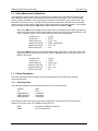
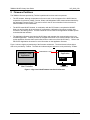
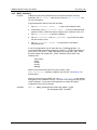
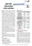
Figure 1 shows a high level partitioning of the firmware architecture. The black boxes indicate object
code to be provided by Teridian. The white box indicates object and source code provided by Teridian.
Serial/SPI Host
Application
UART/RS232 or SPI
Application
M-API
Host Controller
CE
78M6618
Figure 1: High Level Host/Firmware Interface Architecture
8
Rev. 1.00
UG_6618_029
78M6618 M-API Library User Guide
3 Build Environment and Software/Firmware Configuration
The Metrology Application Programming Interface (M-API) is built using Keil Compiler version 8.02,
although any Keil version 7.00 or higher is also compatible.
The M-API library is built using specific default configuration as listed in Section 4. Any changes to these
default values may require a rebuild of the library.
The M-API library is built with careful consideration of Flash Management and Bank Switching
mechanism, the Keil’s standard STARTUP.A51 was modified to support the specific Bank Switching; thus
it is included in the MAPI library. Bank assignment is defined during linking time; therefore it is not
possible to have a single library spreading out into different banks. Thus, the MAPI library was built as 4
separate smaller libraries for the purpose of bank assignments. It is the responsibility of the Application
Programmer to make sure the libraries are to be placed at their specific banks for MAPI to work properly.
Application code maybe placed anywhere within the 4 banks except at the last 8K of Bank 3 as it is
designated for CE usage (see Table 2).
3.1
Program and RAM Memory
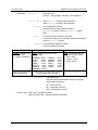
The 78M6618 IC has a total of 4K data RAM and 128K bytes of program/Flash memory. The 4K-bytes of
data RAM is shared between the CE and the MPU. It is partitioned and reserved for each controller as
follows:
Table 1: Data RAM Shared by CE and MPU
Address
Usage
0x0000 – 0x059F
Reserved for CE Data RAM (1.4K).
0x05A0 – 0x0FFF
Reserved for use by MPU (2.6K).
Because the 80515 can only address up to 64 KB of program memory space from 0x0000 to 0xFFFF, the
78M6618 was designed such that access to program memory above 0x7FFF is controlled by the
FL_BANK[1:0] bits in register (SFR 0xB6). These two bits hold the value of the most significant bits of
Flash program address. Flash memory is partitioned as follows:
Table 2: Flash Memory Shared by the CE and MPU Code
Address
(hex)
Memory
Technology
Memory
Type
Name
Typical Usage
0x0000 –
0x1DFFF
Flash
Memory
Non-volatile
Program memory
MPU Program and
non-volatile data
120 KB
0x1E000 –
0x1FFFF
Flash
Memory
Non-volatile
Program memory
CE program
8 KB max.
Memory Size
(bytes)
Since the 78M6618 uses different memory banks, access to specific region of Flash requires careful
consideration of how the code is spread out. The CE code is currently placed at the highest 8K region of
Flash.
Rev. 1.00
9
78M6618 M-API Library User Guide
3.2
UG_6618_029
Build Configuration
The accompanying PDU demo application source code has been set up to link to the libraries as described
in the following sections.
3.2.1
Bank Assignments
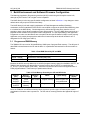
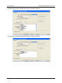
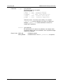
The 78M6618 IC has 4 banks of Flash at 32K each. The banks are divided such as: Common, Bank #1,
Bank #2 and Bank #3. The project is setup to identify these banks as shown here:
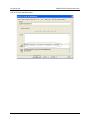
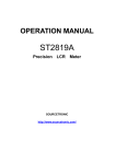
The common library (6618CMAPIW.LIB) resides in Code Bank ‘Common’:
10
Rev. 1.00
UG_6618_029
78M6618 M-API Library User Guide
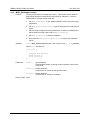
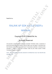
The Bank1 library (6618B1_MAPIW.LIB) resides in Code Bank “Bank #1”:
The Bank 2 library (6618B2_MAPIW.LIB) resides in Code Bank “Bank #2”:
Rev. 1.00
11
78M6618 M-API Library User Guide
UG_6618_029
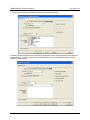
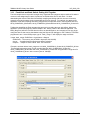
The Bank 3 library (6618B3_MAPIW.LIB) resides in Code Bank “Bank #3”:
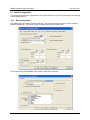
In addition to bank assignment to the libraries, the application code is also assigned to specific banks as
follows with main.c resides in the common code bank and the rest of the application source reside in
Bank #3 as shown below:
12
Rev. 1.00
UG_6618_029
78M6618 M-API Library User Guide
The whole ‘CLI’ group of files is assigned to Bank #3 as shown below.
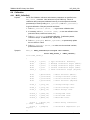
Note: To find out which file resides in which bank, it is best to look at Keil’s Mapped file (*.M51 file where *
is the object code name). In the example application, the top part of the 6618_CLIMAPIWv2_00.M51, the
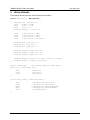
following is shown (bank number is highlighted and reformatting of the text was done for easy reading):
BL51 BANKED LINKER/LOCATER V6.22, INVOKED BY:
C:\KEIL\C51\BIN\BL51.EXE
//Application files’ bank assignment:
COMMON {main.obj},
BANK3 {io.obj},
BANK3 {cli.obj},
BANK3 {cmd_misc.obj},
BANK3 {menu.obj},
BANK3 {cmd_sfr.obj},
BANK3 {cmd_MAPI.obj},
BANK3 {cmd_ce.obj},
BANK3 {cmd_IOMap.obj},
BANK3 {c_serial.obj},
//Library files’ bank assignment:
COMMON
{..\Library\6618C_MAPIW.LIB
(?C_STARTUP,
?BANK?SWITCHING,
DEFAULTS, SET_DEFAULTS, FLASH, LIBRARY, CE, TRIP, TMR0, STM, TSC, IO6618,
IRQ, MATH, SFRS, SER0CLI)},
BANK1
{..\Library\6618B1_MAPIW.LIB
(FREQ,
METER,
PEAK_ALERTS,
PHASE_ANGLE, POWER, PWRFACT, RMS_METER, VAH, VARH, WH)},
BANK2 {..\Library\6618B2_MAPIW.LIB (CE6618, COMPENSATION, MEASURE, RMS)},
BANK3 {..\Library\6618B3_MAPIW.LIB (CE6618A01_1_CE, CE6618A01_1_DAT,
ACCESS, MAPI, CMD_CALIBRATE, IOMAP, RTC, SPI_SLAVE)}
TO 6618_CLIMAPIWv2_00.abs
Rev. 1.00
13
78M6618 M-API Library User Guide
3.2.2
UG_6618_029
Flash/Code Space Assignment
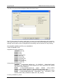
In addition to bank assignments, there are three files that are part of the Bank 3 library
(6618B3_MAPIW.LIB) that are assigned to a very specific area of Flash within Bank 3. The Flash/Code
space assignment is necessary in order to keep the images of the CE code, CE data and Energy
Measurement Constant isolated. These assignments are: CE data image is to reside at starting address:
0xDFFE; the CE code image is to reside at starting address: 0xEFFE; and the constants defined in a file
called Defaults to reside at starting address: 0x7C00. This information is presented in the M51 file as
follows:
BANKAREA (0X8000, 0XFFFF) RAMSIZE (256) DISABLEWARNING (6) BANK3
(?CO?CE6618A01_1_DAT (0XDFFE), ?CO? CE6618A01_1_CE (0XEFFE)) CODE (0X0000-0XFFFF,
?CO?DEFAULTS (0X7C00)) XDATA (0X05A0-0X0FFF) PDATA (0X0200).
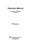
And the setup for these files is shown below for defaults:
14
Rev. 1.00
UG_6618_029
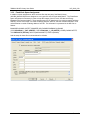
78M6618 M-API Library User Guide
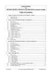
And for CE code and data images:
Rev. 1.00
15
78M6618 M-API Library User Guide
3.2.3
UG_6618_029
Flash/Code and Bank Switch: Putting It All Together
The Keil compiler does not produce a single nicely organized and contiguous object code/hex file when it
comes to bank assignments; instead, it produces an individual hex file for each bank. So when
downloading the code to Flash after successfully compiling and linking with Keil, the user will need to
manually select and program each corresponding hex file into its bank. For example, the attached CLI
application code after compiling and linking using the Keil compiler will result in three separate hex files:
6618_CLIMAPIWv2_00.abs.H01, 6618_CLIMAPIWv2_00.abs.H02 and 6618_CLIMAPIWv2_00.abs.H03.
Teridian has simplified the Flash programming process by providing the user with a Bank_Merge.exe
application (a Dos base program), which resides in the ‘.\library’ folder of the attached zipped file. The
Bank_Merge.exe will take in all the three hex files, as described above, and merge them into one single
contiguous hex file that can be downloaded using the Signum ICE debugger or the Teridian’s TFP2 flash
programmer’s tool. At the DOS prompt, type in: “bank_merge /?” will display its usage as follows:
Usage: bank_merge <ROM Size> <Input Name> <Output>
<ROM Size> - The memory size of ROM in kbyte (64,128,192,256)
<Input> - Compiled bank hex files' name without extension
<Output> - Output file name. MUST have '.hex' extension
Example, as shown below: bank_merge.exe 128 6618_CLIMAPIWv2_00.abs 6618_CLIMAPIV2_00.hex
This example merges the three (3) Keil compiled hex files '6618_CLIMAPIWv2_00.abs.H01',
'6618_CLIMAPIWv2_00.abs.H02' and '6618_CLIMAPIWv2_00.abs.H03' and generates a single hex file
‘6618_CLIMAPIWv2_00.hex’ with a memory size of 128kbyte.
16
Rev. 1.00
UG_6618_029
78M6618 M-API Library User Guide
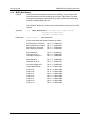
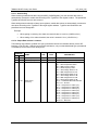
4 M-API Libraries
The libraries are designed and partitioned to be placed at specific banks as follows:
Library Name
Flash Bank
Approx. Size
Purpose
Wide Band Option
6618C_MAPIW.LIB
Common
19K
Keeps all common (frequently called) code.
Includes (but not limited to): Interrupt service
routines, timer APIs, Relay APIs, Serial 0 APIs,
Flash management, access to all metering
registers.
6618B1_MAPIW.LIB
Bank 1
6K
Reserved for metering calculations.
6618B2_MAPIW.LIB
Bank 2
0.5K
6618B3_MAPIW.LIB
Bank 3
9K + 4K
More metering calculations.
The first/lower address of 9K is used mostly for
calibration, accessing registers and the actual
library API calls. The bottom/higher address of
4K is used up by CE.
The current CLI and M commands code is also
residing here, which takes up another 9K.
*Narrow Band Option
6618C_MAPIN.LIB
Common
19K
Keeps all common (frequently called) code.
Includes (but not limited to): Interrupt service
routines, timer APIs, Relay APIs, Serial 0 APIs,
Flash management, access to all metering
registers.
6618B1_MAPIN.LIB
Bank 1
6K
Reserved for metering calculations.
6618B2_MAPIN.LIB
Bank 2
0.5K
6618B3_MAPIN.LIB
Bank 3
9K + 4K
More metering calculations.
The first/lower address of 9K is used mostly for
calibration, accessing registers and the actual
library API calls. The bottom/higher address of
4K is used up by CE.
The current CLI and M commands code is also
residing here, which takes up another 9K.
* Narrow-Band libraries are not fully tested and will be released in the near future.
Rev. 1.00
17
78M6618 M-API Library User Guide
UG_6618_029
4.1 Library Initialization and Operation
4.1.1
4.1.2
MAPI_Init()
Purpose
Initialize all critical variables, start the Compute Engine (CE) and its interrupts,
start the MPU timer, setup all default values. The application must first call this
API before any attempt to use other APIs.
Synopsis
Void MAPI_Init(
Parameters
None.
Return Codes
None.
void );
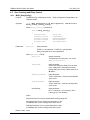
MAPI_SelectMeter() – future feature
Purpose
The accumulation interval is obtained by setting specific values in the
PRE_SAMPS, SUM_CYCLES, FIR_LEN, MUX_DIV registers along with specific
selectable CE Clock rates. At present time, this API library is using a default
configuration with FIR_LEN at its highest/fastest rate, FIR=0/138 CK32/CE
cycles. The default value is PRE_SAMPS = 50 and SUM_CYCLES = 60 with
MUX_DIV = 10. This constitutes an accumulation interval of approximately 1
second.
In future releases, this API may be used to select a different accumulation
interval based on a chosen time interval such as: 250ms, 500ms, or 1 second.
Synopsis
Bool
MAPI_SelectMeter ( enum eAccInterval TimeInterval );
Enum eAccInterval { _250ms, _500ms, _1sec, _2sec);
Parameters
TimeInterval
Input parameter.
Return Codes
TRUE (1) – Successful operation.
FALSE(0) – Failed operation. Default values are used, which is 1 second
accumulation interval.
4.1.3
18
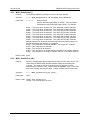
MAPI_MeterRun()
Purpose
Run this function in foreground mode to reset the watchdog, update all
measurement outputs, and compare data to Min/Max thresholds. Once
MAPI_Init is called, the CE will update all atomic measurements every
accumulation interval. It is the task of the application to put this API into its main
loop so that it can post-process the data just imported from the CE. If this API is
called more than once within the same accumulation interval, no changes will be
updated and a FALSE will be returned. Typically, the application layer will then
call MAPI_MeterStatus() to check for any alarm conditions and call
MAPI_GetSetRegister()to get updated measurement data.
Synopsis
Bool
Parameters
None.
Return Codes
TRUE (1) – New data has been updated.
FALSE(0) – No change from the last update run.
MAPI_MeterRun ( void );
Rev. 1.00
UG_6618_029
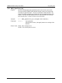
4.1.4
78M6618 M-API Library User Guide
MAPI_MeterStatus()
Purpose
Run this function periodically to detect any error/warning. Any non-zero value
returned indicates some failure/warning has occurred. MPU Output Threshold
levels and mask settings for the alarms can be read, modified, and saved using
the MAPI_GetSetRegister() API call.
Note: Registers 02,03,102,103 also contain meter status for direct access via SPI
interface.
Synopsis
void
Parameters
Common_Status
MAPI_MeterStatus ( unsigned long Common_Status,
unsigned long WB_Status,
unsigned long NB_Status );
Output parameter.
A 32-bit word status that indicates statuses as follows:
Rev. 1.00
Min Temperature exceeded
Max Temperature exceeded
Min Frequency exceeded
Max Frequency exceeded
Bit 0 = 1
Bit 1 = 1
Bit 2 = 1
Bit 3 = 1
//0000 0001
//0000 0002
//0000 0004
//0000 0008
SAG A detected
Under Min VA on A
Over Max Voltage on A
Bit 4 = 1 //0000 0010
Bit 5 = 1 //0000 0020
Bit 6 = 1 //0000 0040
SAG B detected
Under Min VB on B
Bit 7 = 1 //0000 0080
Bit 8 = 1 //0000 0100
Over max Voltage on B
Line/Neutral Reversal
Bit 9 = 1 //0000 0200
Bit 10 = 1 //0000 0400
Creep on IA
Creep on IB
Creep on IC
Creep on ID
Creep on IE
Creep on IF
Creep on IG
Creep on IH
Bit 16 = 1 //0001 0000
Bit 17 = 1 //0002 0000
Bit 18 = 1 //0004 0000
Bit 19 = 1 //0008 0000
Bit 20 = 1 //0010 0000
Bit 21 = 1 //0020 0000
Bit 22 = 1 //0040 0000
Bit 23 = 1 //0080 0000
19
78M6618 M-API Library User Guide
WB_Status
UG_6618_029
Output Parameter
A 32-bit word status that indicates status of wide band measurements as follows:
20
Over max current on Outlet 1
Min Power Factor exceeded on Outlet 1
Max Power Factor exceeded on Outlet 1
Bit 0 = 1 //0000 0001
Bit 1 = 1 //0000 0002
Bit 2 = 1 //0000 0004
Over max current on Outlet 2
Min Power Factor exceeded on Outlet 2
Max Power Factor exceeded on Outlet 2
Bit 3 = 1 //0000 0008
Bit 4 = 1 //0000 0010
Bit 5 = 1 //0000 0020
Over max current on Outlet 3
Min Power Factor exceeded on Outlet 3
Max Power Factor exceeded on Outlet 3
Bit 6 = 1 //0000 0040
Bit 7 = 1 //0000 0080
Bit 8 = 1 //0000 0100
Over max current on Outlet 4
Min Power Factor exceeded on Outlet 4
Max Power Factor exceeded on Outlet 4
Bit 9 = 1 //0000 0200
Bit 10 = 1 //0000 0400
Bit 11 = 1 //0000 0800
Over max current on Outlet 5
Min Power Factor exceeded on Outlet 5
Max Power Factor exceeded on Outlet 5
Bit 12 = 1 //0000 1000
Bit 13 = 1 //0000 2000
Bit 14 = 1 //0000 4000
Over max current on Outlet 6
Min Power Factor exceeded on Outlet 6
Max Power Factor exceeded on Outlet 6
Bit 15 = 1 //0000 8000
Bit 16 = 1 //0001 0000
Bit 17 = 1 //0002 0000
Over max current on Outlet 7
Min Power Factor exceeded on Outlet 7
Max Power Factor exceeded on Outlet 7
Bit 18 = 1 //0004 0000
Bit 19 = 1 //0008 0000
Bit 20 = 1 //0010 0000
Over max current on Outlet 8
Min Power Factor exceeded on Outlet 8
Max Power Factor exceeded on Outlet 8
Bit 21 = 1 //0020 0000
Bit 22 = 1 //0040 0000
Bit 23 = 1 //0080 0000
Over Max Current Total
Reserved
Bit 24 = 1 //0100 0000
Bits 25:31
Rev. 1.00
UG_6618_029
78M6618 M-API Library User Guide
NB_Status
Output Parameter.
A 32-bit word status that indicates status of narrow band measurements as
follows:
Return Codes
Rev. 1.00
Over max NB current on A
Min Power Factor exceeded on A
Max Power Factor exceeded on A
Bit 0 = 1 //0000 0001
Bit 1 = 1 //0000 0002
Bit 2 = 1 //0000 0004
Over max NB current on B
Min Power Factor exceeded on B
Max Power Factor exceeded on B
Bit 3 = 1 //0000 0008
Bit 4 = 1 //0000 0010
Bit 5 = 1 //0000 0020
Over max NB current on C
Min Power Factor exceeded on C
Max Power Factor exceeded on C
Bit 6 = 1 //0000 0040
Bit 7 = 1 //0000 0080
Bit 8 = 1 //0000 0100
Over max NB current on D
Min Power Factor exceeded on D
Max Power Factor exceeded on D
Bit 9 = 1 //0000 0200
Bit 10 = 1 //0000 0400
Bit 11 = 1 //0000 0800
Over max NB current on E
Min Power Factor exceeded on E
Max Power Factor exceeded on E
Bit 12 = 1 //0000 1000
Bit 13 = 1 //0000 2000
Bit 14 = 1 //0000 4000
Over max NB current on F
Min Power Factor exceeded on F
Max Power Factor exceeded on F
Bit 15 = 1 //0000 8000
Bit 16 = 1 //0001 0000
Bit 17 = 1 //0002 0000
Over max NB current on G
Min Power Factor exceeded on G
Max Power Factor exceeded on G
Bit 18 = 1 //0004 0000
Bit 19 = 1 //0008 0000
Bit 20 = 1 //0010 0000
Over max NB current on H
Min Power Factor exceeded on H
Max Power Factor exceeded on H
Bit 21 = 1 //0020 0000
Bit 22 = 1 //0040 0000
Bit 23 = 1 //0080 0000
Over max NB Current Total
Bit 24 = 1 //0100 0000
None.
21
78M6618 M-API Library User Guide
4.2
4.2.1
UG_6618_029
Library Inputs and Outputs
MAPI_GetSetRegister()
Purpose
Get or Set the value of a specific register location. An error will be returned if the
address is out of range or within the restricted location. Care must be taken when
calling this API to Set the value into a register. A call to MAPI_UpdateCE() and/or
MAPI_UpdateMPU() will be necessary if it shall be permanently saved into Flash.
There are three types of registers: MPU, CE and I/O Hardware Control. The range of
address indicates the type of registers as follows:
0x0000 – 0x03FF: MPU Address. Can also be accessed via SPI interface.
0x0400 – 0x07FF: CE Address. No direct access via SPI interface.
0x2000 – 0x20FF: Hardware I/O Control Address. No direct access via SPI.
When calling this function, make sure the documented Reg.Address is or’ed with
the specific type of register (CE or MPU or I/O RAM) defined such as:
enum REG_TYPE {
MPU_ADDRESS
CE_ADDRESS
RI_ADDRESS
Synopsis
= 0x0000,
= 0x0800,
= 0x2000};
enum MAPI_RC MAPI_GetSetRegister( bool Operation,
struct _Reg_t *Reg)
Where _Reg_t is defined as:
Struct _Reg_t
{
Unsigned Integer
Unsigned Long
Unsigned Char
Unsigned Integer
};
22
Address;
Value;
TypeSize;
ScaleFactor;
Rev. 1.00
UG_6618_029
Parameters
78M6618 M-API Library User Guide
Operation
Input parameter.
TRUE(1) – Set Operation, FALSE(0) – Get Operation.
Struct _Reg_t
When Operation=TRUE, Output parameter.
When Operation=FALSE, Input parameter.
Address
Two-byte address location.
Address where its content will be extracted
(Operation=FALSE) or stored (Operation = TRUE).
Note,
Value
Four-byte value to be stored or retrieved.
Content from Address to be extracted (Operation=FALSE) or
stored (Operation = TRUE).
TypeSize
Type and Size of register’s content.
This byte is defined as follows:
Bit 8
Bit 7…4
SIGNED: Register value
is a signed value
(1-negative, 0-positive).
Typically used for power
factor, phase adjust.
TYPE: Register value is one of the
following types:
INTEGER – 0x00
FLOAT
– 0x10
IRMS_T – 0x20
VRMS_T – 0x30
IRMS_M – 0x40
VRMS_M – 0x50
CONTROL – 0x60
CONFIG – 0x70
POWER – 0x18
ENERGY – 0x28
FREQ
– 0x38
COUNT
– 0x48
TIMER
– 0x58
Bit 3…1
SIZE: Indicates storage size
(in bytes) of register where:
1 – char, 1-byte
2 - Integer , 2-byte
4 - Word, 4-byte
Used by API call to determine formulae
for data scaling and conversion
ScaleFactor
Output parameter.
This byte indicates presentation format of the register
content defined as follows:
10 – Tenth unit factor.
100 – Hundredth unit factor.
1000 – Thousandth unit factor.
Return Codes
Rev. 1.00
MAPI_OK – successful operation.
MAPI_RESTRICTED – specified address is restricted.
23
78M6618 M-API Library User Guide
UG_6618_029
4.2.1.1 Auto-Scaling
When retrieving measurement data using the MAPI_GetSetRegister() call, the returned data value is
automatically converted to usable data according to the TypeSize of the register location. The predefined
TypeSize and ScaleFactor are also returned.
When writing alarm thresholds to library input registers, usable data values are automatically converted to
raw values according to the TypeSize of the target register address. TypeSize and ScaleFactor are
predefined and non-changeable.
Example:
•
When getting or retrieving VRMS data, the returned value is in mVRMS (120000 mVRMS)
•
When setting a VRMS alarm threshold, the value is entered in VRMS (120.000 VRMS)
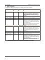
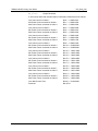
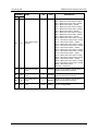
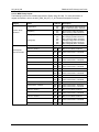
4.2.1.2 Output Data Address Locations
The following output data is updated once per accumulation interval and available directly via the SPI
interface or via API calls. With the current M-API architecture, only one bandwidth data type (narrowband
or wideband) can be used in each library build.
MPU
ADDRESS
WB
NB
00
100
01
101
02
24
102
NAME
Delta Temperature
Line Frequency
Alarm Status
(common)
LSB
TYPE
0.1 °C
0.01 Hz
FLOAT
FREQ
DESCRIPTION
Temperature difference from 22 °C.
Line Frequency.
Bit 0 – MIN Temperature Alarm.
Bit 1 – MAX Temperature Alarm.
Bit 2 – MIN Frequency Alarm.
Bit 3 – MAX Frequency Alarm.
Bit 4 – SAG Voltage Alarm for VA.
Bit 5 – MIN Voltage Alarm for VA.
Bit 6 – MAX Voltage Alarm for VA.
Bit 7 – SAG Voltage Alarm for VB.
Bit 8 – MIN Voltage Alarm for VB.
Bit 9 – MAX Voltage Alarm for VB.
Bit 10 – Line/Neutral Reversal Detected
Bits 11:15 – Unused.
Bit 16 – Creep Alert for Outlet 1 (IA).
Bit 17 – Creep Alert for Outlet 2 (IB).
Bit 18 – Creep Alert for Outlet 3 (IC).
Bit 19 – Creep Alert for Outlet 4 (ID).
Bit 20 – Creep Alert for Outlet 5 (IE).
Bit 21 – Creep Alert for Outlet 6 (IF).
Bit 22 – Creep Alert for Outlet 7 (IG).
Bit 23 – Creep Alert for Outlet 8 (IH).
Bits 24:31 – Reserved.
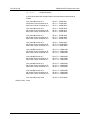
Rev. 1.00
UG_6618_029
MPU
ADDRESS
WB
NB
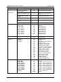
78M6618 M-API Library User Guide
NAME
LSB
TYPE
DESCRIPTION
Bit 0 – MAX Current Alarm – Outlet1
Bit 1 – MIN Power Factor Alarm– Outlet1
Bit 2 – MAX Power Factor Alarm– Outlet1
Bit 3 – MAX Current Alarm – Outlet2
Bit 4 – MIN Power Factor Alarm– Outlet2
Bit 5 – MAX Power Factor Alarm– Outlet2
Bit 6 – MAX Current Alarm – Outlet3
Bit 7 – MIN Power Factor Alarm– Outlet3
Bit 8 – MAX Power Factor Alarm– Outlet3
Bit 9 – MAX Current Alarm – Outlet4
Bit 10 – MIN Power Factor Alarm– Outlet4
Bit 11 – MAX Power Factor Alarm– Outlet4
Bit 12 – MAX Current Alarm – Outlet5
Bit 13 – MIN Power Factor Alarm– Outlet5
Bit 14 – MAX Power Factor Alarm– Outlet5
Bit 15 – MAX Current Alarm – Outlet6
Bit 16 – MIN Power Factor Alarm– Outlet6
Bit 17 – MAX Power Factor Alarm– Outlet6
Bit 18 – MAX Current Alarm – Outlet7
Bit 19 – MIN Power Factor Alarm– Outlet7
Bit 20 – MAX Power Factor Alarm– Outlet7
Bit 21 – MAX Current Alarm – Outlet8
Bit 22 – MIN Power Factor Alarm– Outlet8
Bit 23 – MAX Power Factor Alarm– Outlet8
Bit 24 – MAX Total Current
Bits 25:31 – Reserved.
03
103
Alarm Status (outlet
specific)
04
104
Over Current Event
Count
1
INTEGER
Number of accumulation intervals where
value exceeded alarm threshold
05
105
Under Voltage Event
Count
1
INTEGER
Number of accumulation intervals where
value exceeded alarm threshold
06
106
Over Voltage Event
Count
1
INTEGER
Number of accumulation intervals where
value exceeded alarm threshold
07
107
Volts
mVrms
VRMS_T
AC Line Voltage (RMS)
Rev. 1.00
25
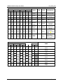
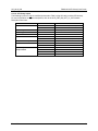
78M6618 M-API Library User Guide
UG_6618_029
Outlet 1
WB
NB
MPU ADDRESS
Outlet 2
Outlet 3
WB
NB
WB
NB
Outlet 4
WB
NB
08
108
10
110
18
118
20
09
109
11
111
19
119
0A
10A
12
112
1A
0B
10B
13
113
0C
10C
14
0D
10D
0E
0F
NAME
LSB
TYPE
DESCRIPTION
120
Active
Power
mW
POWER
21
121
Energy
mWh
ENERGY
11A
22
122
Cost
mUnits
FLOAT
Active Power (per
accum interval).
Accumulated
Energy
Accumulated Cost
1B
11B
23
123
Current
mArms
IRMS_T
RMS Current.
114
1C
11C
24
124
Reactive
Power
mW
POWER
15
115
1D
11D
25
125
Apparent
Power
mW
POWER
10E
16
116
1E
11E
26
126
Power
Factor
–
FLOAT
10F
17
117
1F
11F
27
127
Phase
Angle
–
FLOAT
Reactive Power
(per accum
interval).
Apparent Power
(per accum
interval).
Power factor.
(output will be
between -1.00 and
1.00)
Phase angle.
(output will be
between 180.000
and -180.000)
MPU ADDRESS
NAME
Outlet 5
WB
NB
Outlet 6
WB
NB
Outlet 7
WB
NB
Outlet 8
WB
NB
28
128
30
130
38
138
40
140
48
148
Active
Power
29
129
31
131
39
139
41
141
49
149
Energy
2A
12A
32
132
3A
13A
42
142
4A
14A
Cost
2B
12B
33
133
3B
13B
43
143
4B
14B
Current
2C
12C
34
134
3C
13C
44
144
4C
14C
2D
12D
35
135
3D
13D
45
145
4D
14D
2E
12E
36
136
3E
13E
46
146
-
-
2F
12F
37
137
3F
13F
47
147
-
-
26
Outlet Total
WB
NB
Reactive
Power
Apparent
Power
Power
Factor
Phase
Angle
Rev. 1.00
UG_6618_029
78M6618 M-API Library User Guide
4.2.1.3 MPU Library Inputs
The following inputs can be modified (and saved to Flash) using API calls. For more information on
register descriptions, refer to the 6618_PDU_S8_URT_V1_00 Firmware Description Document.
Category
Common Alarm
Threshold
Outlet Specific
Alarm Thresholds
Name
Description
Temperature
240
241
Min Temperature Alarm Threshold
Max Temperature Alarm Threshold
Frequency
242
243
Min Frequency Alarm Threshold
Max Frequency Alarm Threshold
Voltage (A)
Voltage (B)
244
245
246
247
248
249
WB NB
SAG (A) Voltage Alarm Threshold
Min Voltage (A) Alarm Threshold
Max Voltage (A) Alarm Threshold
SAG (B) Voltage Alarm Threshold
Min Voltage (B) Alarm Threshold
Max Voltage (B) Alarm Threshold
Current - Outlet 1
250
269
Max Current Alarm Threshold
Power Factor - Outlet 1
251
252
26A
26B
Power Factor Alarm - Threshold
Power Factor Alarm + Threshold
Current - Outlet 2
253
26C
Max Current Alarm Threshold
Power Factor - Outlet 2
254
255
256
26D
26E
26F
Power Factor Alarm - Threshold
Power Factor Alarm + Threshold
Max Current Alarm Threshold
Power Factor - Outlet 3
257
258
270
271
Power Factor Alarm - Threshold
Power Factor Alarm + Threshold
Current - Outlet 4
259
272
Power Factor - Outlet 4
25A
25B
273
274
Max Current Alarm Threshold
Power Factor Alarm - Threshold
Power Factor Alarm + Threshold
Current - Outlet 5
25C
275
Max Current Alarm Threshold
Power Factor - Outlet 5
25D
25E
276
277
Power Factor Alarm - Threshold
Power Factor Alarm + Threshold
Current - Outlet 3
Rev. 1.00
MPU
Address
Current - Outlet 6
25F
278
Max Current Alarm Threshold
Power Factor - Outlet 6
260
261
279
27A
Power Factor Alarm - Threshold
Power Factor Alarm + Threshold
Current - Outlet 7
262
27B
Max Current Alarm Threshold
Power Factor - Outlet 7
263
264
27C
27D
Power Factor Alarm - Threshold
Power Factor Alarm + Threshold
Current - Outlet 8
265
27E
Max Current Alarm Threshold
Power Factor - Outlet 8
266
267
27F
280
Power Factor Alarm - Threshold
Power Factor Alarm + Threshold
Total Current
268
281
Max Current Alarm Threshold
27
78M6618 M-API Library User Guide
Category
Name
UG_6618_029
MPU Address
Description
Common Alarm Mask for
Status Registers
282
Common Alarm Mask for Alarm
DIO4
283
Alarm Mask for Common Alarm
DIO4
WB Alarm Mask for Status
Registers
284
Alarm Mask for WB Status
WB Alarm Mask for Alarm DIO4
285
Alarm Mask for WB Alarm DIO4
NB Alarm Mask for Status
Registers
286
Alarm Mask for NB Status
NB Alarm Mask for Alarm DIO4
287
Alarm Mask for NB Alarm DIO4
Sensor Scaling
Voltage - V(A)
Voltage - V(B)
Current -Outlet 1
Current - Outlet 2
Current - Outlet 3
Current - Outlet 4
Current - Outlet 5
Current - Outlet 6
Current - Outlet 7
Current - Outlet 8
200
201
202
203
204
205
206
207
208
209
VMAX A
VMAX B
IMAX Outlet 1 (IA)
IMAX Outlet 2 (IB)
IMAX Outlet 3 (IC)
IMAX Outlet 4 (ID)
IMAX Outlet 5 (IE)
IMAX Outlet 6 (IF)
IMAX Outlet 7 (IG)
IMAX Outlet 8 (IH)
Cost Factor
Cost
20E
20F
Cost per KWh
Cost Unit string
Calibration
Calibration
Configuration
Parameters
21D
21E
21F
220
221
222
223
224
225
226
227
228
229
22A
22B
22C
22D
22E
22F
Calibration Status
Unused
Tolerance on Phase Calibration
Calibration Type
Calibration Voltage (Target)
Calibration Current (Target)
Calibration Phase (Target)
Tolerance on Voltage Calibration
Tolerance on Current Calibration
Average Count for Voltage
Average Count for Current
Max Iterations for Voltage
Max Iterations for Current
Tolerance on Watts Calibration
Average Count for Watts
Max Iterations for Watts
Calibration WRATE
Calibration Temperature
Calibration Wattage (Target)
Creep Threshold
Voltage (VA)
Voltage (VB)
Current -Outlet 1
Current - Outlet 2
Current - Outlet 3
Current - Outlet 4
Current - Outlet 5
Current - Outlet 6
Current - Outlet 7
Current - Outlet 8
Frequency
230
231
232
233
234
235
236
237
238
239
23A
23B-23F
VA creep
VB creep
Imin(IA) - "creep" or squelch level
Imin(IB) - "creep" or squelch level
Imin(IC) - "creep" or squelch level
Imin(ID) - "creep" or squelch level
Imin(IE) - "creep" or squelch level
Imin(IF) - "creep" or squelch level
Imin(IG) - "creep" or squelch level
Imin(IH) - "creep" or squelch level
VA min for Freq creep
Unused
Alarm Masks
28
Alarm Mask for Common Status
Rev. 1.00
UG_6618_029
78M6618 M-API Library User Guide
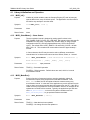
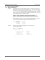
4.2.1.4 CE Library Inputs
The following inputs can only be modified (and saved to Flash) using API calls (no direct SPI access).
For more information on register descriptions, refer to the 6618_PDU_S8_URT_V1_00 Firmware
Description Document.
CATEGORY
Calibration
Phase Adjust
CE Configuration
Pulse Rate
Quantization Corrections
Temperature Compensation
SAG Detection
More Temperature
Compensation
Rev. 1.00
CE ADDRESS
10 - 17
18,19
1A - 21
22
23
25 - 2C
35 – 3C
3D
3E
3F
40
41
42
43
DESCRIPTION
Calibration Gain IA-IH (Outlet 1-8)
Calibration Gain VA, VB
Phase Adjust IA - IH
CE State
Wrate
Quantization offset Outlet 1 to Outlet 8
Quantization offset IA - IH (Outlet 1-8)
Temperature Gain Adjust
SAG Threshold on VA
SAG Threshold on VB
Degree Scale
ppm / ˚c
2
ppm / ˚c
Temperature Calibration Value
29
78M6618 M-API Library User Guide
4.3
4.3.1
UG_6618_029
Flash Management
Memcpy_rx()
Purpose
Write to Flash the content data from a specific RAM location. If the length of the
source and the starting ROM location cause the write operation to span more than
one 1024-byte Flash page, the Read/Erase/Verify/Write will take place on all the
pages involved. An erase operation will result in the Flash contents being set to
0xFF. CE will be disabled during execution of this API. After the write, this API will
validate the write by comparing the Flash content against the RAM content and the
return code is reflected from this comparison.
Note1: When calling this API, CE must be turned off. See MAPI_CEOff and
MAPI_CEOn APIs in the sections above.
Note2: it is the task of the application to setup the specific Flash bank before calling
this API. An example use of this API is as follows:
FL_BANK = BANK_CE;
ok = memcpy_rx ((int8r_t *) ROMData, (int8x_t *) RAMData, ROMSIZE);
FL_BANK = saved_bank;
Where FL_BANK is SFR 0xB6; and BANK_CE is defined to be Bank 3.
Synopsis
Bool memcpy_rx ( Unsigned char code *dst,
Unsigned char xdata *src,
Unsigned integer len );
Parameters
dst
src
len
Return Codes
Input parameter.
Specifies starting ROM address of Flash to be written (destination).
Input parameter.
Use contents at this RAM address location as the source data.
Input parameter.
Length (in bytes) of data to write to Flash.
TRUE if the Write was successful.
FALSE if the Write was not completed.
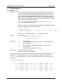
Note: To avoid accidental write to Flash, this function requires a ‘flash write’ confirmation from the
application layer. This confirmation is done such as follows: there shall be a function called
get_buff(), at application level, which returns a pointer of Xdata whose content is checked as
the following:
uint8x_t xdata *bptr;
bptr = get_buff ();
if ((']'
(')'
('C'
('C'
('C'
('U'
('U'
)
30
==
==
==
==
==
==
==
toupper
toupper
toupper
toupper
toupper
toupper
toupper
(*(bptr
(*(bptr
(*(bptr
(*(bptr
(*(bptr
(*(bptr
(*(bptr
+
+
+
+
+
+
+
0))
0))
0))
0))
1))
1))
1))
&&
&&
&&
&&
&&
&&
&&
'U'
'U'
'A'
'L'
'C'
'C'
'M'
==
==
==
==
==
==
==
toupper
toupper
toupper
toupper
toupper
toupper
toupper
(*(bptr
(*(bptr
(*(bptr
(*(bptr
(*(bptr
(*(bptr
(*(bptr
+
+
+
+
+
+
+
1)))
1)))
1)))
1)))
2)))
2)))
2)))
||
||
||
||
||
||
Rev. 1.00
UG_6618_029
4.3.2
78M6618 M-API Library User Guide
Memcpy_xr()
Purpose
Use to write to Flash the content data to a specific RAM location. Note, it is the
task of the application to setup the specific Flash bank before calling this API. An
example use of this API is as follows:
FL_BANK = BANK_CE;
memcpy_xr (RAMData, ROMData, ROMSIZE);
FL_BANK = saved_bank;
Where FL_BANK is SFR 0xB6; and BANK_CE is defined to be Bank 3.
Synopsis
Void memcpy_xr ( Unsigned char xdata *dst,
Unsigned char code *src,
Unsigned integer len );
Parameters
dst
src
len
Return Codes
4.3.3
Input parameter
Specifies starting RAM address to be written (destination).
Input parameter
Use contents at this ROM/Flash address location as the source data.
Input parameter
Length (in bytes) of data to write to RAM.
TRUE if the Write was successful.
FALSE if the Write was not completed.
Memcpy_xx()
Purpose
Use to copy data from an xdata location to another xdata location.
Synopsis
Void memcpy_xx ( Unsigned char xdata *dst,
Unsigned char xdata *src,
Unsigned integer len );
Parameters
dst
src
len
Return Codes
Rev. 1.00
Input parameter
Specifies starting RAM address to be written (destination).
Input parameter
Use contents at this RAM address location as the source data.
Input parameter
Length (in bytes) of data to write to RAM.
None.
31
78M6618 M-API Library User Guide
4.3.4
4.3.5
32
UG_6618_029
MAPI_UpdateMPU()
Purpose
Update the MPU contents permanently into Flash. The MPU measurement input
and calibration default values are stored in Flash. During power up, this content
is copied to XRAM to be used as a working copy. The application can change
some of the values using the MAPI_GetSetRegister(). This change only
takes effect in the XRAM copy of the data. To permanently save the data into
Flash, the application must exclusively call this function to perform the permanent
save. This function is not to, and should not, be called too often as Flash Write
does have a life-expectancy. It is typically used after the part is calibrated
successfully to save the coefficient values. See the 6618_MAPICLIW.uproj for
sample usage of this API. In order for this function to perform properly, the CE
must be turned off by calling MAPI_CEOff().
Synopsis
Bool MAPI_UpdateMPU ( void );
Parameters
none
Return Codes
TRUE – Successful write of MPU data to Flash.
FALSE – Write was not successful; perhaps CE is still running.
MAPI_UpdateCE()
Purpose
Update the CE Data contents permanently into Flash. The CE Data Image is
programmed into Flash, starting at address 0xDFFE. During power up, its
content is copied to XRAM to be used as a working copy. Though it is NOT
recommended to change any CE Data, occasionally such needs arise, such as
changing the IMAX, VMAX or WRATE values. The application can change the
values of these configurable registers using the MAPI_GetSetRegister().
This change only takes effect in the XRAM copy of the data. To permanently
save the data into Flash, the application must exclusively call this function to
perform the permanent save into its specific location of Flash. This function is
not, and should not, be called too often as Flash Write does have a lifeexpectancy. See the 6618_MAPICLIW.uproj for sample usage of this API. In
order for this function to perform properly, the CE must be turned off by calling
MAPI_CEOff().
Synopsis
Bool
Parameters
None.
Return Codes
TRUE – Successful write of MPU data to Flash.
FALSE – Write was not successful; perhaps CE is still running.
MAPI_UpdateCE ( void );
Rev. 1.00
UG_6618_029
4.3.6
4.3.7
78M6618 M-API Library User Guide
MAPI_CEOn()
Purpose
Turn CE on. After calling MAPI_Init(), CE is turned on. This API is available
to the application to manually control the CE, particularly when reading/writing to
Flash (writing to Flash is not allowed when CE is on).
Synopsis
void MAPI_CEOn ( void );
Parameters
None.
Return Codes
None.
MAPI_CEOff()
Purpose
Turn CE off. When writing to flash, the CE must be turned off. This API is
necessary with MAPI_UpdateCE, MAPI_UpdateMPU or memcpy_rx calls.
Synopsis
void
Parameters
None.
Return Codes
None.
Rev. 1.00
MAPI_CEOff ( void );
33
78M6618 M-API Library User Guide
UG_6618_029
4.4 Calibration
4.4.1
MAPI_CalSetGet()
Purpose
Set or Get Calibration reference and tolerance parameters as specified in the
MPU_CParms_t structure. New values are kept in RAM only. When all
calibration data is setup and calibrated correctly, it can be kept and recorded,
permanently in Flash by calling MAPI_UpdateCE() and MAPI_UpdateMPU().
A typical calibration of the part proceeds as follows:
1. Call MAPI_CalSetGet (FALSE, ….) to get current calibration data.
2. If necessary, call MAPI_CalSetGet (TRUE,…) to set new calibration data
(tolerance values, referenced values, etc.).
3. Call MAPI_Calibrate() to start the calibration. If calibration passes,
continue to step 4. If calibration fails, repeat step 1.
4. Call MAPI_UpdateCE() and MAPI_UpdateMPU() to permanently update
the new values in Flash.
5. Call MAPI_CalSetGet (FALSE,…) to make sure the new data is written,
preserved and correct.
Synopsis
MAPI_RC
MAPI_CalSetGet(IN unsigned char SetData,
Struct MPU_CParms_t
*MAPI_CParams);
Struct MPU_CParms_t
{
uint8_t
float
float
float
int16_t
C_Tcal;
C_Wcal;
C_Vcal;
C_Ical
C_Pcal;
//
//
//
//
//
float
float
float
float
C_Wtolerance;
C_Vtolerance;
C_Itolerance;
C_Ptolerance;
//
//
//
//
uint8_t
uint8_t
uint8_t
C_Vavg_cnt;
C_Iavg_cnt;
C_Wavg_cnt;
// Voltage Average count.
// Current Average count.
// Watts Average count.
uint16_t
uint16_t
uint16_t
C_Vmax_cnt;
C_Imax_cnt;
C_Wmax_cnt;
// Voltage Max count.
// Current Max count.
// Watts Max count.
uint16_t
C_Wrate_cal;
(~.32Kh). Read-Only
uint16_t
C_Tempcal;
degree).
};
34
Type calibration. Read-Only.
Wattage calibration target (Watts).
Voltage calibration target (Vrms).
Current calibration target (Arms).
Phase calibration target (Degrees).
Watts Tolerance (Watts).
Voltage Tolerance (Vrms).
Current Tolerance (Arms).
Phase Tolerance (degrees).
// Wrate during calibration
// Calibration temperature (0.1
Rev. 1.00
UG_6618_029
Parameters
78M6618 M-API Library User Guide
SetData
Input parameter.
TRUE(1) – Set calibration data as specified in MPU_CParms_t.
FALSE(0) – Get current calibration data and return values in MPU_CParms_t.
MAPI_CParams:
C_Tcal
Input parameter – read-only. Calibration type. None(0x00).
C_Wcal
Output parameter (SetData = FALSE), Input parameter (SetData = TRUE)
Referenced Wattage calibration value (in Watts). Default = 120W.
C_Vcal
Output parameter (SetData = FALSE), Input parameter (SetData = TRUE)
Referenced Voltage calibration value (Vrms) . Default = 120V.
C_Ical
Output parameter (SetData = FALSE), Input parameter (SetData = TRUE)
Referenced Current calibration value (Arms). Default = 1A.
C_Pcal
Output parameter (SetData = FALSE), Input parameter (SetData = TRUE)
Referenced Phase calibration value (in 0.1 C Degrees). Default = 0 degree.
C_Wtolerance
Output parameter (SetData = FALSE), Input parameter (SetData = TRUE).
Watts Tolerance (Watts). Default = 0.01W or 10mW.
C_Vtolerance
Output parameter (SetData = FALSE), Input parameter (SetData = TRUE)
Voltage Tolerance (Vrms). Default = 10mV.
C_Itolerance
Output parameter (SetData = FALSE), Input parameter (SetData = TRUE)
Current Tolerance (Arms). Default = 10mA.
C_Ptolerance
Output parameter (SetData = FALSE), Input parameter (SetData = TRUE)
Phase Tolerance (degrees). Default = 0.1 Degree.
C_Vavg_cnt
Output parameter (SetData = FALSE), Input parameter (SetData = TRUE)
Voltage Average count. Default = 3.
C_Iavg_cnt
Output parameter (SetData = FALSE), Input parameter (SetData = TRUE)
Current Average count. Default = 3.
C_Wavg_cnt
Output parameter (SetData = FALSE), Input parameter (SetData = TRUE)
Watts Average count. Default = 3.
C_Vmax_cnt
Output parameter (SetData = FALSE), Input parameter (SetData = TRUE)
Maximum number of voltage reads to test for pass/fail result. Default = 10.
C_Imax_cnt
Output parameter (SetData = FALSE), Input parameter (SetData = TRUE)
Maximum number of current reads to test for pass/fail result. Default = 10.
C_Wmax_cnt
Output parameter (SetData = FALSE), Input parameter (SetData = TRUE)
Maximum number of Watts reads to test for pass/fail result. Default = 10.
C_Wrate_cal
Output parameter.
Wrate use during calibration (~.32kh). Read-only.
C_Tempcal
Output parameter (SetData = FALSE), Input parameter (SetData = TRUE).
Calibration temperature. In 0.1 degree unit.
Return Codes
Rev. 1.00
MAPI_OK
MAPI_ERROR
//Calibration succeeded.
//Calibration failed.
//For more detailed descriptions of the failure, call MAPI_CALStatus().
35
78M6618 M-API Library User Guide
4.4.2
UG_6618_029
MAPI_Calibrate()
Purpose
Calibrate the part using referenced meter values and tolerance values as
specified in the MPU_CParms_t data structure (see the MAPI_CalSetGet API
for more information).
A typical application shall use this API as follows:
1. Call MAPI_CalSetGet (FALSE, ….) to get current calibration data.
2. If necessary, call MAPI_CalSetGet (TRUE,…) to set new calibration data
(tolerance values, referenced values, average count, maximum count, etc.).
3. Call MAPI_Calibrate() to start the calibration.
4. Call MAPI_UpdateCE() and MAPI_UpdateMPU() to permanently update
the new values in Flash.
5. Call MAPI_CalSetGet (FALSE,…) to make sure the new data is
written/preserved.
It is up to the application level to select the CAL_TYPE appropriately. It is
recommended that temperature calibration (CTYPE = C_TEMP) shall always be
part of CAL_TYPE; thus, C_TEMP shall always be OR’ing with c_type. When
this API is called with multiple CAL_TYPEs, calibration will be done in the
following order:
Temperature,
Phase,
Voltage,
Current,
Wattage.
Make sure the referenced values are setup correctly, using
MAPI_CalSetGet(); otherwise, calibration will not pass. See Section 4 for
default values.
When the return code is not MAPI_OK, call MAPI_CalStatus() to get detailed
descriptions of the calibration error(s). If an error occurs during this call, the part
is NOT calibrated. It is the task of the application to call this API again if
recalibration of the part is necessary.
Synopsis
36
MAPI_RC
MAPI_Calibrate(IN enum CAL_TYPE c_type,
IN Unsigned Char Outlets);
Rev. 1.00
UG_6618_029
Parameters
78M6618 M-API Library User Guide
c_type
Input parameter.
The following types are acceptable:
Enum CAL_TYPE {
C_WATT
= 0x01 – Calibrate Wattage.
C_VOLT
= 0x02 – Calibrate Voltage.
C_CURRENT
= 0x04 – Calibrate Current.
C_PHASE = 0x08 – Calibrate Phase Adjust.
C_TEMP
= 0x10 – Calibrate Temperature.
}
Calibration source. The values can be OR’ing. For example:
C_WATT | C_VOLT indicate calibration to be done on Voltage and
Wattage; C_TEMP | C_VOLT indicate calibration to be done on
Voltage and Temperature.
Outlets
Return Codes
Rev. 1.00
Input parameter
Bit representations of outlet # to be calibrated. For example: 0x03
represents outlet #1 and 2 to be calibrated. 0xFF represents all eight
outlets to be calibrated.
MAPI_OK
MAPI_ERROR
//Calibration passed.
//Calibration failed. Call MAPI_CalStatus() for specifics.
37
78M6618 M-API Library User Guide
4.4.3
UG_6618_029
MAPI_GetVoltageCurrent()
Purpose
Get the present values of Voltage and Current . This function can be useful for
determining referenced voltage and current values for calibration. Follow the
steps below for a sample usage of this API:
1. Call MAPI_CalSetGet() to get default calibration values and present chip
temperature.
2. Call MAPI_GetVoltageCurrent() to get the Voltage and Current at the IC
inputs
3. Set new target Voltage and Current parameters, if needed, correlating to the
values obtained in step 2 with a call to MAPI_CalSetGet().
4. Call MAPI_Calibrate() to start the calibration.
5. As a check call MAPI_GetVoltageCurrent() to confirm new calibrated
values.
Synopsis
void
MAPI_GetVoltageCurrent( OUT struct VIT_t
*VIT_Params);
Where VIT_t is defined as:
struct VIT_t
{
Unsigned char Channel;
float Current_I;
float Current_V;
};
Parameters
Channel
Input parameter.
Channel/outlet number (1 through 8) where present Current value
will be read.
Current_I Output parameter.
Present value of Current for the specified outlet.
Current_V Output parameter
Present value of Voltage for Voltage A.
Return Codes
38
None.
Rev. 1.00
UG_6618_029
4.4.4
78M6618 M-API Library User Guide
MAPI_CalStatus()
Purpose
Run this function if MAPI_Calibrate returns error code to get the exact status
of the failure(s).
Synopsis
void
Parameters
Cal_Status
MAPI_CalStatus ( unsigned long CAL_Status );
Output parameter.
A 32-bit word status that indicates statuses as follows:
Return Codes
Rev. 1.00
Voltage A Cal failed
Voltage B Cal failed
Bit 1 = 1
Bit 2 = 1 (N/A at present time)
Phase A Cal failed
Current A/outlet 1 Cal failed
Watt A/outlet 1 Cal failed
Bit 3 = 1
Bit 4 = 1
Bit 5 = 1
Phase B Cal failed
Current B/outlet 2 failed
Watt B/outlet 2 failed
Bit 6 = 1
Bit 7 = 1
Bit 8 = 1
Phase C Cal failed
Current C/outlet 3 failed
Watt C/outlet 3 failed
Bit 9 = 1
Bit 10 = 1
Bit 11 = 1
Phase D Cal failed
Current D/outlet 4 failed
Watt D/outlet 4 failed
Bit 12 = 1
Bit 13 = 1
Bit 14 = 1
Phase E Cal failed
Current E/outlet 5 failed
Watt E/outlet 5 failed
Bit 15 = 1
Bit 16 = 1
Bit 17 = 1
Phase F Cal failed
Current F/outlet 6 failed
Watt F/outlet 6 failed
Bit 18 = 1
Bit 19 = 1
Bit 20 = 1
Phase G Cal failed
Current G/outlet 7 failed
Watt G/outlet 7 failed
Bit 21 = 1
Bit 22 = 1
Bit 23 = 1
Phase H Cal failed
Current H/outlet 8 failed
Watt H/outlet 8 failed
Bit 24 = 1
Bit 25 = 1
Bit 26 = 1
None.
39
78M6618 M-API Library User Guide
4.5
4.5.1
UG_6618_029
Zero Crossing and Relay Control
MAPI_RelayConfig()
Purpose
Read/Write relay configuration values.
channels/outlets.
Relay configuration is applicable to all
Synopsis
void MAPI_RelayControl( IN Bool Operation, OUT/IN struct
Relay_Config_t Relay_Config);
Where Relay_Config_t is defined as:
struct Relay_Config_t
{
Unsigned
Unsigned
Unsigned
Unsigned
Unsigned
Char
Integer
Integer
Integer
Char
Relay_CTL;
SeqDlyTime;
DeEnergizedTime;
EnergizedTime;
InvertPNonLatch;
};
Parameters
Operation
Input parameter.
TRUE (1) = set operation. FALSE (0) = get operation,
Relay_Config will all be output parameter.
When Operation = TRUE:
Relay_CTL
Output parameter.
This parameter is output only. It is set via
MAPI_RelayControl().
SeqDlyTime
Input parameter.
Set the new Sequence Delay Time in 10ms
units. Delay time is time between turning
Relays ON (close circuit). Default value is 10
100ms.
DeEngergizedTime
Input parameter.
Time in mseconds + 1msecond to delay after
open circuit.
EngergizedTime
Input parameter.
Time in msecond + 1msecond to delay after
close circuit.
InvertPolarity
Input parameter.
Bit 1 = Polarity (0 = non-inverted). Bit 0 =
Latch type (0 = non-latched).
Notes:
Sequence Delay Time will be used between turning relays ON.
Energized Delay Time is used as the delay time to wait
immediately after a zero-crossing before close circuit.
DeEnergized Delay Time is used as delay time to wait
immediately after a zero-crossing before open circuit.
Return Codes
40
None.
Rev. 1.00
UG_6618_029
4.5.2
78M6618 M-API Library User Guide
MAPI_RelayControl ()
Purpose
Turning Relay ON/OFF (close/open circuit) on all eight channels.
Synopsis
void
Parameters
Channels
MAPI_RelayControl( IN unsigned char Channels);
Input parameter.
Each bit indicates turning ON(1) or OFF(0). The bit’s position
represents the specific channel/outlet number. For example:
0x01h – Turn relay ON on channel 1/A. Turn relays OFF all other channels.
0x02h – Turn relay ON on channel 2/B. Turn relays OFF all other channels.
0x04h – Turn relay ON on channel 3/C. Turn relays OFF all other channels.
0x08h – Turn relay ON on channel 4/D. Turn relays OFF all other channels.
0x10h – Turn relay ON on channel 5/E. Turn relays OFF all other channels.
0x20h – Turn relay ON on channel 6/F. Turn relays OFF all other channels.
0x40h – Turn relay ON on channel 7/G. Turn relays OFF all other channels.
0x80h – Turn relay ON on channel 8/H. Turn relays OFF all other channels.
Multiple channels can be turned ON with a single call to this API by setting 1 at
the bits representing the channels. For example:
0x81h – Turn relay ON on channels 1&8/A&H. Turn relays OFF all others.
0xFFh – Turn relay ON on all channels.
0x00h – Turn relay off of all channels.
0x0Fh – Turn relay ON on all 4 lower channels and OFF of all 4 higher channels
0xF0h – Turn relay ON on all 4 higher channels and OFF of all 4 lower channels
Return Codes
4.5.3
None.
MAPI_CloseCircuit_0X()
Purpose
Get zero-crossing status when positioning from open circuit to close circuit. The
value returned TRUE/FALSE indicates whether Voltage zero-crossing has
occurred. The usage of this API is intended to be for when the circuit is
transitioning from open to close. This API uses the hardware Timer 1 in the case
when zero crossing does not take place. A delay of 20ms is set for such break.
Synopsis
bool
Parameters
None.
Return Codes
TRUE – Zero crossing occurs.
FALSE – Zero crossing does not occur.
Rev. 1.00
MAPI_CloseCircuit_0X( void );
41
78M6618 M-API Library User Guide
4.5.4
42
UG_6618_029
MAPI_OpenCircuit_0X()
Purpose
Get zero-crossing status when transitioning from close circuit to open circuit.
The value returned TRUE/FALSE indicates whether current zero-crossing has
occurred for a specific channel. There is no indication of either direction. The
usage of this API is intended to be for when the circuit is transitioning from close
to open. This API uses the hardware Timer 1 in the case when zero crossing
does not take place. A delay of 12ms is set for such break.
Synopsis
bool
Parameters
Channel
Return Codes
TRUE – Zero crossing occurs.
FALSE – Zero crossing does not occur.
MAPI_OpenCircuit_0X( unsigned char Channel );
Input parameter.
Channel/outlet number (1 through 8) where zero crossing will be
detected.
Rev. 1.00
UG_6618_029
4.6
78M6618 M-API Library User Guide
Soft-Timers
There are eight soft-timers in the 8051 Timer 0. Only six of these timers are available to application level
as two are used internally by the library. The timer is a fixed 10-milisecond time increment. When
TSC_Init() is called, the timer will be started and setup. It also calls MAPIstm_init() so the
application layer does NOT need to call MAPIstm_init().
4.6.1
4.6.2
MAPIstm_init()
Purpose
Initialize soft-timers variables and structures.
Synopsis
void
Parameters
None.
Return Codes
None.
MAPIstm_init ( void );
MAPIstm_fn_start()
Purpose
Start a soft-timer with a call-back function pointer. Upon expiration of the timer,
execute the function then remove/free the timer.
Synopsis
unsigned integer
Parameters
tenms _count
Input parameter.
Number of counts (in 10ms units) passed to execute the call
back function fn_ptr.
*fn_ptr
Input parameter.
Pointer to the call-back function to execute when the
tenms_count has expired. The function should be a
reentrant.
Return Codes
*MAPIstm_fn_start (unsigned integer tenms_count,
void (code *fn_ptr) (void))
NULL_PTR: if there is no more soft-timer available. Or,
The address of where tenms_count value is stored, and counted down, is
returned. This is useful when the application needs to stop the timer at any time
before it is expired.
4.6.3
MAPIstm_run()
Purpose
Keep the soft-timers updated and current. This API shall be called in the
application’s main loop after MAPIstm_fn_start() is used. This is where
fn_ptr (in MAPIstm_fn_start() above) is processed.
Synopsis
void
Parameters
None.
Return Codes
None.
Rev. 1.00
MAPIstm_run ( void );
43
78M6618 M-API Library User Guide
4.6.4
MAPIstm_wait()
Purpose
Delay processing for a fixed time (in 10ms increment). Typically use when it is
necessary to wait for something to stabilize.
Synopsis
void
Parameters
DelayTime
Return Codes
None.
MAPIstm_wait ( IN unsigned integer DelayTime );
4.7
Miscellaneous APIs
4.7.1
MAPI_GetCEName()
4.7.2
44
UG_6618_029
Input parameter
Wait (hold up CPU processing) for DelayTime * 10ms.
Purpose
Get the CE name embedded as part of the CE data. The CE name size is 24
bytes and these exact 24 bytes will be returned in the XDATA string pointed to by
ptr.
Synopsis
void
Parameters
ptr
Return Codes
None.
MAPI_GetCEName ( unsigned char xdata *ptr );
Output parameter.
The CE name will be returned at the xdata location pointed to by
ptr. For version 1.00 CE release, the string will look as follows:
CE6618_PDU_S8_A01_V1_0.
MAPI_SoftReset()
Purpose
Reset the MPU, this includes stopping the CE, and setting all registers to
hardware Power-On Reset values.
Synopsis
void
Parameters
None.
Return Codes
None.
MAPI_SoftReset ( Void );
Rev. 1.00
UG_6618_029
4.8
4.8.1
78M6618 M-API Library User Guide
Serial/RS232 Interface
MAPI_UARTInit()
Purpose
Configure the communication speed, flow control, character parity and number of
stop bits. The serial interrupt service routine is NOT maskable, the interrupt
vector is set internally. Xon/Xoff will always be enabled. Non-parity, 8 data bit, 1
stop bit is the only supported configuration. The only thing the application can
change is the baud rate.
Synopsis
Bool MAPI_UARTInit ( IN enum SERIAL_SPD speed)
Parameters
speed:
Input parameter
This selects the communication speed. Possible values are:
_RATE_300
_RATE_600,
_RATE_1200,
_RATE_2400,
_RATE_4800,
_RATE_9600,
_RATE_19200,
_RATE_38400,
Return Codes
4.8.2
0
1
2
3
4
5
6
7 (default)
None.
MAPI_UARTTx()
Purpose
Setup the Tx buffer before sending data to the PC UART. Subsequent call to this
API will append the buffer to the existing transmittal buffer. An application should
call this API immediately after calling MAPI_UARTInit().
Synopsis
enum SERIAL_RC data MAPI_UARTTx ( U08x xdata *buffer, U16 len )
Parameters
buffer
Len
Return Codes:
Input parameter.
Specifies a pointer to the data buffer containing data to send to the
PC UART.
Input parameter.
Specifies the current number of bytes to be sent.
S_EMPTY
Successful transmission.
S_PENDING, Successful transmission thus far but not yet finished.
Where return code SERIAL_RC is defined as: Enum SERIAL_RC.
After calling this API, an application can make sure all bytes were transmitted by
checking that MAPI_TxLen() returns a 0.
Rev. 1.00
45
78M6618 M-API Library User Guide
4.8.3
4.8.4
MAPI_TxLen()
Purpose
Number of bytes transmitted thus far.
Synopsis
Unsigned integer MAPI_ TxLen ( void )
Parameters
None.
Return Value
Unsigned integer specifying the number of bytes left in the Tx buffer, i.e. the
remaining bytes to be sent.
MAPI_UARTRx()
Purpose
Setup the receive buffer and start receiving. Always call this function after
MAPI_UARTInit() to make sure the receive buffer is available. Subsequent
call to this API will append the data to the existing buffer queue, if data is being
received.
Synopsis
uint16_t MAPI_UARTRx ( U08x xdata *buffer, U16 len )
Parameters
buffer
len
Return Codes
4.8.5
46
UG_6618_029
Input parameter.
Specifies a pointer to the data buffer to store the data received from
the PC UART.
Input parameter.
Specifies the maximum number of bytes to receive at any one time.
Unsigned integer specifying the number of bytes fetched thus far. Use
MAPI_RxLen() to keep track of the remaining number of bytes unfetched in the
Rx buffer.
MAPI_RxLen()
Purpose
Number of bytes received thus far.
Synopsis
Unsigned Integer MAPI_ RxLen ( void )
Parameters
None.
Return Value
Unsigned integer specifying the number of bytes in the queued buffer.
Rev. 1.00
UG_6618_029
4.9
78M6618 M-API Library User Guide
SPI Interface
78M6618 have dedicated segment-pins SEG3(PCLK),SEG4(PSDO),SEG5(PCSZ) and SEG6(PSDI) for
SPI interface. When SPI interface is used for communication, these pins should not be used for other
purpose.
4.9.1
4.9.2
4.9.3
MAPI_SPIInit()
Purpose
Initializes the SPI interface, enables the hardware port and interrupt, and
initializes the required SPI registers.
Synopsis
void MAPI_SPI_init ( void )
Parameters
None
Return Codes
None.
MAPI_SPICmd_Pending()
Purpose
Indicates whether the MPU has received a new SPI command.
Synopsis
bool MAPI_SPICmd_Pending()
Parameters
None
Return Codes
TRUE - A SPI command is waiting to be processed.
FLASE - There is no pending SPI command.
MAPI_SPIGet_Cmd()
Purpose
This MAPI returns the command code and data for the currently pending SPI
command.
Synopsis
void MAPI_SPI_get_cmd(struct spi_cmd_param *cmd_param)
Where spi_cmd_param is defined as
struct spi_cmd_param
{
uint8_t cmd_s;
uint32_t data_s;
};
Parameters
spi_cmd_param
cmd_s
Output parameter.
Contains the value of the pending SPI command, e.g. 0x81(relay
control), 0x89(CE off), etc.
data_s Contains the data of the pending SPI commands, if applicable.
Return Codes
Rev. 1.00
None
47
78M6618 M-API Library User Guide
UG_6618_029
5 Library Defaults
The following default values are used to build the M-API library:
struct MPU_CParms_t MPU_CParams =
{
Unsigned Char Channels = 0
float
C_Wcal = 120W
float
C_Vcal = 120V
float
C_Ical = 1A
Unsigned Integer t C_Pcal = 0
float
float
float
float
C_Wtolerance
C_Vtolerance
C_Itolerance
C_Ptolerance
=
=
=
=
10mA
10mV
10mA
0.1 degree
Unsigned Char C_Vavg_cnt = 3
Unsigned Char Iavg_cnt = 3
Unsigned Char C_Wavg_cnt = 3
Unsigned Integer C_Vmax_cnt = 10
Unsigned Integer C_Imax_cnt = 10
Unsigned Integer C_Wmax_cnt = 10
Unsigned Integer C_Wrate_cal = 2840 (shall not change)
Unsigned Integer C_Tempcal (read-only)
};
#define DefaultTIQ
10 //Default Time Increment Query
struct VIT_t xdata mapi_tVIT =
{
0x01,
//Channel 1
0.00,
//Current_I;
0.00,
//Current_V;
};
struct Relay_Config_t xdata RlyConfig =
{
0x00,
//unsigned char Relay_CTL;
0x64,
//unsigned int SeqDlyTime;
0x01,
//unsigned int DeEnergizedTime;
0x01,
//unsigned int EnergizedTime;
0x00,
//InvertPNonLatch
};
48
Rev. 1.00
UG_6618_029
78M6618 M-API Library User Guide
Revision History
Revision
1.00
Rev. 1.00
Date
9/15/2010
Description
First publication.
49