1
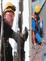
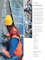
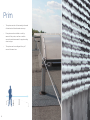
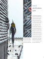
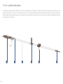
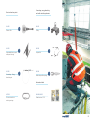
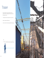
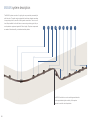
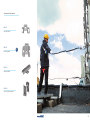
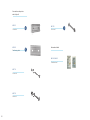
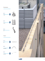
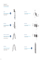
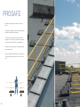
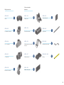
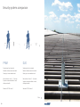
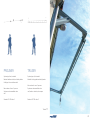
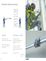
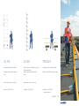
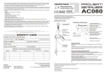
PERMANENT FALL
PROTECTION
SYSTEMS
2014
www.protekt.com.pl
TECHNICAL DEPARTMENT:
Marcin Włuka
tel. +48 42 29 29 534
Mobile tel. 605 477 655
[email protected]
Janusz Paczesny
tel. +48 42 29 29 533
Mobile tel. 603 399 655
[email protected]
Zygmunt Zrobek
tel. +48 42 29 29 530
[email protected]
MAINTENANCE DEPARTMENT SERVICE:
Tomasz Canert
tel: +48 42 29 29 518
fax: +48 42 680 20 93
[email protected]
FOREIGN SALES DEPARTMENT
Agata Raczyńska
tel. +48 42 29 29 503
[email protected]
Agnieszka Sekura
tel. +48 42 29 29 504
[email protected]
Monika Tychaczka
tel. +48 42 29 29 506
[email protected]
Karolina Rojek
tel. +48 42 29 29 508
[email protected]
Agata Łukasiewicz
tel. +48 42 29 29 510
[email protected]
TABLE OF
CONTENTS:
Fall protection systems by PROTEKT
5
Installing and maintenance
6
Prim
8
Duo
14
Proliner
20
Traser
24
Maran
28
SKC Block
34
AC 360
38
AC 510
42
AC 520
46
PROSAFE
52
Systems comparison
56
PROTECT YOUR LIFE – USE IMAGINATION
All systems and devices manufactured by PROTEKT
ensure safety during work where fall from height is
real hazard.
Our equipment is used in wide variety of working
fields - working at height, depth and mining, rescue
and many others. We offer both individual protection
equipment (safety harness, energy absorbers and
lanyards) and complete permanent safety systems,
which are described in details in the catalogue
herein. We pay special attention to user comfort and
reliability of our products. We always try to match all
requirements of our customers as close as possible.
All products manufactured by PROTEKT are CE certified and officially allowed to be used.
For all current detailed information concerning application and technical parameters please contact our
office or one of our technical-commerce consultants.
Telefon:
+48 42 680-20-83
+48 42 292-95-00
Fax:
+48 42 680-20-93
E-mail:
[email protected]
www.protekt.com.pl
4
FALL PROTECTION SYSTEMS CLASSIFICATION
Vertical movement
Horizontal movement
Cable
systems
Prim system
Duo system
Proliner system
Cable
systems
SKC BLOCK
AC 360
Rail
systems
Traser system
Maran system
Rail
systems
AC 520
Railing
systems
PROSAFE system
Safaty
Ladders
AC 510
5
Installing
and maintenance
A client who is willing to install a fall protection
system at his premises should contact the
PROTEKT technical-commerce consultant,
in order to arrange a conceptual meeting and
inspection of existing facilities. The consultant
will prepare technical project of the fall protection system and will send official commercial
offer. After accepting the offer, the client is
supposed to provide in written form formal order for materials and installation service. Once
the order is received, PROTEKT representative
contacts the client’s project coordinator in
order to develop suitable work schedule.
Already installed systems are to be subjected to inspection, performed by PROTEKT
company or other authorized service, every
12 months. In order to perform the service
or maintenance job, one should contact the
PROTEKT company.
Technical and commercial
consultants:
Marcin Włuka
tel. +48 42 29 29 534
Mobile tel. 605 477 655
[email protected]
Janusz Paczesny
tel. +48 42 29 29 533
Mobile tel. 603 399 655
[email protected]
Maintenance department - service:
Tomasz Canert
tel: +48 42 29 29 518
fax: +48 42 680 20 93
[email protected]
7
7
Prim
8
•
The system consists of a horizontal guide made
of stainless steel 8mm diameter wire rope.
•
Prim system can be installed on roofs, by
means of foot posts, as well as on walls to
secure horizontal movement for people working
close to edges.
•
The system can be reconfigured for up to 7
users at the same time.
Universal,
cable fall protection
system
Sequence of passing the carabiner
(which is a part of PPE) through the
intermediate point of the system without compromising on fall protection.
The PRIM system is an anchorage device
for personal protective equipment against
fall from height. The system can be easily
reconfigured that is perfectly capable of
providing protection despite different construction features of a building it is installed
on. The system is intended to be used by
3 persons at the same time. Optionally
it can be reconfigured for up to 7 users.
The system consists of a horizontal guide,
which is made of stainless steel wire rope
with a diameter of 8 mm, equipped with an
energy absorber and a tensioner. The guide
is connected to a permanent construction
in structural anchor points by a wide range
of available foot posts or anchorage plates.
The user is attached directly to the anchoring cable with a carabiner, being a part of
the personal protective equipment against
fall from height. The device complies with
the EN 795 class C standard and is admissible to be used in blast hazard areas.
9
9
Opis systemu PRIM
PRIM cable fall protection system is an anchorage device
1. end, structural anchoring elements, such as foot posts or
In case of PRIM system, the carabiners, being a part of
class C that complies with EN 795 standard, as well as
anchorage plates,
personal protective equipment, are used as movable anchor-
FprCEN/TS16415 document. It is intended to be used by 3
2. intermediate, structural anchoring elements, such as cable
ing points. It is recommended to use oval carabiner, type
persons at the same time. Optionally it can be reconfigured
grabs or cable return rollers,
PROTEKT – AZ011 which has been designed to cooperate
for up to 7 users. The system can be installed to walls of
3. energy absorbers and rope stretching elements,
smoothly with intermediate cable structural anchor points.
buildings or constructions, as well as on roofs or terraces,
4. connecting elements
All components of the system are made of corrosion re-
etc. The system consists of the following elements:
5. steel cable that acts as a guideline for carriage anchor
sistant elements (stainless steel, brass, plastics), or hot-dip
point for personal protective equipment against fall from
galvanized steel.
height,
6. protective equipment,
8
9
10
4
6
10
2
15
3
13
11
5
1
7
12
14
Structural anchor
points:
HL 701
HL 760 A/HL 760 B
Central foot post
Trapezoidal sheet posts
HL 702
HL 101
Side foot post
HL 704
Central foot post
14
9
2-point end structural
anchor point
HL 102
3-point end structural
anchor point
1
8
HL 720 A/HL 720 B
Post for trapezoidal
sheets
11
11
Structural
anchor points:
HL 201
Intermediate structure
anchor point
HL 202
Intermediate structure
anchor point
HL 130
Wall type return roller
(external turn)
HL 140
Wall type return roller
(internal turn)
12
Lanyard sets:
13
5
6
HL 740
Cable return roller
HL 721/722
2-point pivot plate
11
10
HL 500
Lanyard set
HL 501
Stainless steel
lanyard ø 8mm
Information labels
HL 801/HL802
4
Stainless steel / pov
3
Connecting, energy absorbing
and cable stretching elements:
HL 506
Cable clamp with opening
AZ 090
Screw secured connecting
carriage
HL 300
Energy absorber
HL 401
Rope stretcher
7
15
2
12
13
13
Duo
14
•
The system consists of a horizontal guide made
of stainless steel 8mm diameter wire rope.
•
Duo system can be installed on roofs, by means
of foot posts, as well as on walls to secure
horizontal movement for people working close
to edges.
•
he system can be reconfigured for up to 7
T
users at the same time.
•
Slider working as mobile anchoring point allowing for secure movement along the system with
constant protection maintained.
Advanced,
cable fall protection
system.
Sequence of passing the slider which
is being a mobile anchor point, along
the system through the intermediate
point, with constant protection being
maintained.
Horizontal anchoring system DUO is an
anchorage device for personal protective
equipment against fall from height. The
system is intended to be used 3 persons at
the same time. Optionally it can be reconfigured for up to 7 users. DUO system consists of a horizontal guide which is made
of stainless steel rope with diameter of 8
mm and equipped with an energy absorber
and a rope stretcher. The horizontal guide
is fastened to structural anchorage points
of a permanent construction using posts
or anchorage plates. Every person using
the system is attached to personal carriage
carabiner which is a movable anchoring
point of personal protective equipment that
enables free movement along the cable
with constant protection maintained. The
device complies with the EN 795 class C
standard and it is admissible to be used in
blast hazard areas.
15
15
DUO system description
DUO cable fall protection system is an anchorage device
as foot posts or anchorage plates, intermediate, structural
as movable anchoring points to used with intermediate sys-
class C that complies with EN 795 standard. It is intended to
anchoring elements, such as cable grabs or pipe turns,
tem anchoring points and carabiners being a part of personal
be used by 1, 2 or 3 persons at the same time. The system
energy absorbers and rope stretching elements, connecting
protective equipment. All components of the system are
can be installed to walls of buildings, steel constructions, as
elements, steel cable that acts as a guideline for carriage
made of corrosion resistant elements - stainless steel, brass,
well as on roofs or terraces, etc. The system consists of the
anchor point for personal protective equipment.
plastics, or hot-dip galvanized steel.
following elements: end, structural anchoring elements, such
In case of DUO system, the quick-attached sliders are used
1
16
2
3
4
5
6
7
8
9
10
12
11
Structural anchor points:
HL 701
HL 704
Central foot post
Central foot post
HL 702
Side foot post
10
HL 103
2--point end structural
anchor point
1
11
HL 720 A/HL 720 B
Post for trapezoidal sheets
HL 760 A/HL 760 B
Trapezoidal sheet posts
17
17
Structural anchor points:
HL 203
Intermediate structure
anchor point
HL 603
Slider acting as mobile
anchoring point
5
6
HL 204
Cable shield (turn R250)
HL 205
Cable shield (turn R300)
18
7
HL 750
Plate (turn mounting)
HL 724
Plate (system termination)
8
2
Connecting, energy absorbing
and cable stretching elements:
Lanyard sets:
HL 506
HL 500
Cable clamp with opening
AZ 090
Screw secured connecting
4
12
carriage
HL 320
Connecting - Energy absorbing set
3
Lanyard set
9
HL 501
Stainless steel lanyard
ø 8mm
Information labels
HL 804/HL803
Stainless steel / PVC
19
19
Proliner
20
•
The system is intended to be used by maximum
3 persons at the same time.
•
The guide made of stainless steel wire rope with
a diameter of 8 mm is a guide way for the anchor
trolley.
•
The trolley is a mobile anchoring point for person
being protected vertically while moving along the
system.
Easy moving,
horizontal, line
anchorage system
1.
2.
1. Return roller
2. Trolley acting as mobile anchor
point.
The horizontal line anchorage system PROLINER is the C class device, which complies
with the EN 795 standard. The system is
intended to be used by maximum 3 persons
at the same time. All the components of the
PROLINER system are made of stainless
steel. The trolley is a mobile anchor point of
the system for personal protective equipment. It enables to move along the system
simultaneously with the vertical protection.
The guide made of stainless steel wire rope
with a diameter of 8 mm is a guide way
for the anchor trolley. The absorbing set
serves to reduce the forces acting upon a
construction and the return roller adjusts
proper line tension. The system is admissible to be used in blast hazard areas.
21
21
Proliner system description
The horizontal line anchorage system PROLINER is the C class device, which complies with the EN 795 standard. The system is intended to be used by maximum 3 persons at the same time. It
is equipped with the absorbing – tensioning set. The systems that are longer than 12 meters have additional intermediate supports that allow for trolley passing. The trolley is a mobile anchor
point of the system for personal protective equipment. The name plate consists of basic information concerning system use, as well as an individual serial number, installation date (month and
year) and date of next technical check.
1
22
2
3
4
5
6
Connecting, energy absorbing
and cable stretching elements:
Structural anchor points:
HL 420
Return roller
HL 220
Intermediate line support
with pass-through
HL 320
Connecting - Energy
absorbing set
6
4
1
HL 620
Trolley
HL 500
Lanyard set
HL 506
Cable clamp with opening
5
3
2
Information labels
AZ 090
HL 806/HL805
Screw secured connecting carriage
Stainless steel / PVC
23
23
Traser
24
•
Rail horizontal anchorage system made of
galvanized steel, enabling for free movement in
horizontal position.
•
The system serves as protection for 3 persons.
•
Ideal for ramps and platforms
•
It can be used for performing task while hanging.
Rail
anchorage system
TRASER rail anchorage system is a D class
anchorage device, which complies with the
EN 795 standard. The system serves to attach personal protective equipment against
fall from height to a permanent structure.
It also makes it possible to move in the
horizontal direction for up to 3 persons at
the same time. The rail system consists of:
a horizontal rail as a frame, a trolley, which
is a mobile anchor point for the equipment,
end stops of the guide way, rail connectors and elements fastening the guide to a
permanent structure. The rail guide is made
of hot-dip galvanized steel. The trolley, rail
connectors, end stops of the guide way
and the elements fastening the guide to
a permanent structure are made of cold
galvanized steel, stainless steel or plastics.
The system is admissible to be used in blast
hazard areas.
25
25
TRASER system description
The TRASER system provides protection at the same time
connectors (HR301/HR302) stabilizing adjacent elements.
made of galvanized steel, hangers’ joints and trolley guide
for 3 persons connected to it via personal protection equip-
The end of the guide way are terminated and closed with rail
ways are made of plastic. Information labels are made of
ment against fall from height. The system is made of straight
stops (HR501) that prevents from uncontrolled ejection of the
stainless steel or plastic.
(HR201) or bended (HR202) truss segments that create guide
trolley from the guide way. The system includes also hangers
way for the trolley (HR 101). The trolley is a mobile anchor
(HR401), fixing the rail to permanent construction elements,
TEASER horizontal anchorage system meets the require-
point of the system for personal protective equipment. Indi-
as well as information labels (HR801 or HR802). TRASER sys-
ments defined by FprCEN / TS16415.
vidual elements of the rail guide way are interconnected with
tem is made mainly of hot-dip galvanized steel. Screws are
1
26
2
3
4
5
6
7
Structural anchor
points:
HR 401
Hanger
Structural mounting
elements and guide way
6
HR 101
Trolley
HR 501
End block
HR 301
Structural mounting elements and guide way
HR 201-Le
Rail segment (Le – length
in cm)
Rail connector
7
HR 302
X-type rail connector
2
1
5
3
Information label
HR 202
Turn segment
90 deg
4
HR 802/HL801
Stainless steel / PVC
27
27
Maran
28
•
Rail horizontal anchorage system MARAN with
a trolley locking option, creating immobilized
anchoring point.
•
The system is intended to be used by maximum 2
persons at the same time.
•
It can be used for performing task while hanging.
1.
Horizontal rail
anchorage system
2.
3.
1. Rail and anchor plate.
2. End stop.
3. Trolley with end stop and snap
hook.
The system serves to attach personal protective equipment against falls from height
to permanent structures. It also ensures
safe moving. The system is intended to be
used by maximum 2 persons at the same
time, whereby each person is connected
to an individual trolley. The rail system
consists of: a rail as a guide way for a
trolley, which is a mobile anchor point for
personal protective equipment, end stops of
the guide way, rail connectors and elements
fastening the guide to permanent structures. The rail guide is made of aluminium
alloy. The trolley, rail connectors, end stops
of the guide way, elements fastening the
guide to a permanent structure are made of
aluminium alloy, the connecting elements
(bolts) are made of stainless.
29
29
MARAN system description
The MARAN system consists of a rigid guide way mounted permanently to
solid structure. The guide way is equipped with end stops, elements mounting
to supporting structure, as well as rail segments connectors. There is one or
two trolleys installed on the rail that serve as moving anchoring point for personal protective equipment against fall from height. All system components
are made of aluminium alloy, or stainless steel and plastics.
1
2
3
4
5
6
7
8
9
The MR 203 vertical turn can be used to bypass obstacles
on the way, maintaining the continuity of the system.
It cannot be used for vertical protection.
30
Structural anchor points:
MR 401
Mounting plate
MR 402
Mounting plate
3
MR 403
Mounting plate
MR 404
Pipe mounting element
31
31
Structural anchor points
and trolley rail:
MR 301
Connector
MR 302
Reinforcing plate
5
8
MR 730
Screw set
Information labels
MR 802/HL801
Stainless steel
MR 710
Screw set
MR 720
Screw set
32
4
Trolley rail elements:
MR 101
Trolley
MR 501
Bumper
2
9
MR 601
Bolt
Trolley rail
MR 201
Rail
MR 202
Horizontal turn
MR 203
Vertical turn
7
1
6
33
33
SKC-Block
34
•
The system is intended to be mounted on ladders,
chimneys, towers, masts or buildings.
•
The system serves as protection for 1 person.
•
The system is anchorage device, which complies
with the EN 353-1 standard.
1.
2.
1.Upper terminating element - line end
with anchor plate.
2.AC 350 rope grab with AZ 011 carabiner.
.
Vertical anchorage
system designed for
ladders, single user
protection
Guided type rope grab fall arrester device
mounted on a rigid line – the SKC Block
system serves as protection against fall
from height for a person moving on vertical
ladders. The system is intended to be
mounted on all kinds of permanent access
to constructions, e.g. chimneys, towers,
masts or buildings. A rope grab installed
on a steel wire rope with a diameter of 8
mm and connected to a front attaching
buckle of the safety harness is a base of the
system. The essential components of the
system such as a wire rope, rope grab, rope
connector, screw clips and rope tensioner
are made of stainless steel.
35
35
SKC - BLOCK system description
Permanent vertical protection system SKC- BLOCK is a guided-type rope grab fall arrester
on a rigid anchorage line and it is a energy absorbing and connecting element, according
1
9
to the EN 363 standard. The SKC – BLOCK system complies with requirements defined by
the European Union Directive 89/686/EEC. The general system design is presented by the
graphics on the right hand side. The system is composed of vertical guide line, made of
2
stainless steel cable of 8 mm diameter (ref. No AC 850). Lower end of the guide is equipped
with a stainless steel tensioner (ref. No AC 910). Upper termination of the line guide is
attached to a permanent construction by means of screw type carabiner AZ090 made of
stainless steel. The vertical line guide of more than 10m length is equipped with rope guiding element (ref. No AC 921) that protects the line against vibrations caused by wind. The
rope grab slider (ref. No AC 350) is a part of personal protective equipment that is installed
onto the vertical line whenever protection is needed. The slider moves up and down the line
following user’s movement and it blocks itself on the line in case of fall accident, protecting
the user.
3
4
5
Mobile anchoring point
6
AC 350
Rope grab slider mechanism
36
3
1
Structural anchor elements:
AT 160/AT160-i
Side mounting plate (galvanized/stainless steel)
9
Structural connecting elements:
Lanyard set
AZ 090
AC 850
screw type carabiner
AT 161/AT 161-i
AC 910
4-point ladder rung mounting
plate (galvanized/stainless
steel)
Rope tensioner (stainless
steel)
AT 162/AT 162-i
2-point ladder rung mounting
plate (galvanized/stainless
steel)
1
AC 921
Rope guide
2
6
5
Guiding rope
4
Information labels
AC 804/AC 803
Stainless steel / PVC
AT 163/AT 163-i
6-point ladder rung mounting
plate (galvanized/stainless
steel)
AT 165
6-point ladder rung mounting beam (galvanized steel)
37
37
AC 360
38
•
The system is intended to be mounted on ladders,
chimneys, towers, masts or buildings.
•
The system serves as protection for 2 persons.
•
Guided-type fall arrester on a rigid anchorage line,
which complies with the EN 353-1 standard.
1.
2.
1.Energy absorber
2.AC 360 rope grab slider
Vertical rope
anchorage system
offering protection
for 1 or 2 users
AC 360 rope grab guided-type fall arrester
on a rigid anchorage line serves as safeguard and protection against fall from
height for 2 persons moving in a vertical
direction at the same time. The system is
intended to be mounted on all kinds of permanent access (ladders) to constructions,
e.g. chimneys, towers, masts or buildings.
A rope grab installed on a steel wire rope
with a diameter of 8 mm and connected to
a front attaching buckle of safety harness
is the base of the system. The essential
components of the system such as a wire
rope, rope grab, rope connector, screw clips
and rope tensioner are made of stainless
steel. The system conforms to EN 353-1
standard.
39
39
AC 360 system description
Permanent vertical protection system AC 360 is a guided-type rope grab fall arrester on a rigid guide way and
it is a energy absorbing and connecting element, according to the EN 363-1 standard. The AC 360 system
complies with requirements defined by the European Union Directive 89/686/EEC. The general system design
is presented by the graphics. The system is composed of vertical guide line, made of stainless steel cable of 8
mm diameter (ref. No AC 850). Upper end of the line guide is equipped with the energy absorber (ref. No AC 361
/ AC 362). Lower end of the guide is equipped with a stainless steel tensioner (ref. No AC 910). Upper and lower
1
2
3
termination of the line guide is attached to a permanent construction by means of screw type carabiner AZ090
made of stainless steel. The vertical line guide of more than 10m length is equipped with rope guiding element
(ref. No AC 921) that protects the line against vibrations caused by wind. The rope grab slider (ref. No AC 360)
is a part of personal protective equipment that is installed onto the vertical line whenever protection is needed.
The slider moves up and down the line following user’s movement and it blocks itself on the line in case of fall
accident protecting the user.
4
5
Mobile anchoring point
AC 360
Rope grab slider mechanism
6
4
7
1
40
Structural anchor
elements:
Lanyard set
AT 160/AT160-i
AZ 090
Side mounting plate (galvanized/stainless steel)
screw type carabiner
AT 16 /AT 161-i
AC 910
4-point ladder rung mounting
plate (galvanized/stainless
steel)
Rope tensioner
(stainless steel)
AT 162/AT 162-i
AC 361
2-point ladder rung mounting
plate (galvanized/stainless
steel)
1
Energy absorber for a single
user
AT 163/AT 163-i
AC 362
6-point ladder rung mounting
plate (galvanized/stainless
steel)
Energy absorber for 2 users
AT 165
AC 921
6-point ladder rung mounting beam (galvanized steel)
Rope guide
2
7
6
3
AC 850
Guiding rope
5
Information labels
AC 802/AC 801
Stainless steel/ PVC
6
41
41
AC 510
•
AC 510 Ladder with basket conforms to DIN
18 799-1 standard: vertical ladders used for inspection, maintenance and service purposes for
building structures.
•
It is designed to be set on fixed structures such
as chimneys, towers, masts or buildings enabling
vertical movement.
•
It can bet installed wherever it is possible to
attach it to the permanent structure.
42
Facade ladder
with double rail
safety system.
1.
2.
1.Mobile anchoring point - trolley with
self-locking mechanism, energy absorber and carabiner.
2.Ladder rung with anti-slide surface.
AC 510 system is a façade ladder with rail
fall protection system. Self-locking device
with rigid guide - AC 510 system is designed
to prevent falls from height for people
moving in vertical direction. The system is
fixed to the aluminium ladder with double
rail and is designed to be set on fixed structures such as chimneys, towers, masts or
buildings. The essential part of the system
is self-blocking mechanism that can be
fastened on rigid guide. It allows the user to
move vertically being connected to moving
trolley. Self-locking mechanism in the shape
of a trolley can be set on the right or left
side of the ladder. The trolley prevents sudden falls from height. It also has an integrated energy absorber which reduces dynamic
force below 6 kN in case of a fall. The shape
of the trolley prevents from the wrong setup
on the guide. The system consists of 3 m
long segments which enable an easy adjustment of the length of the entire system
on a certain structure. The trolley can move
smoothly along the whole ladder length.
Protection is ensured at the entire length of
the ladder. The AC 510 system conforms to
PN-EN 353-1 standard.
43
43
AC 510 Ladder with basket
The ladder can be attached to walls of the building with M12
lation and use of every rung. The basket of the ladder meets
mechanical or chemical anchors, in case of steel structures
the requirement of DIN 18 799-1 standard. The internal bas-
installation can be done with screws or plates, etc. Every sin-
ket diameter equals 700mm, which is enough to ensure easy
gle 3m element of the ladder should be installed (attached) to
movement inside the basket. The basket has modular design
the permanent structure in at least two points. The maximum
as well. Each segment of it is 1.65m in length and it can be fur-
distance between consecutive support points for the ladder
ther segmented (cutting off part of vertical elements results in
cannot exceed 1.8m. Depending on the total length of the lad-
length reduced to 850mm) maintaining full functionality. The
der one should design both the number of supporting points
total length of the basket needs to be selected to match total
and their localization with respect to permanent structure.
length of the ladder. The upper edge of the basket should be
Installation of supports to side profiles of the ladder is done
levelled with the ladder and the lower end, according to the
by means of 4 or M8 screws on each side. The supports can
standard, it should start 2-3 m above the ladder lower edge,
be easily moved along the whole length of the ladder thanks
thus allowing free access to the ladder. Particular modules of
to screws being mounted inside the “rail” of adder profiles. It
the basket are interconnected by means of screws. Screws
allows for simple adjustment of support place. The supports
are used also to attach the basket to the ladder itself. The up-
are made of galvanized or stainless steel. The ladder is made
per protection railing is designed to secure the user while en-
of aluminium profiles and the basket is made of galvanized
tering and exiting the ladder onto the roof, platform, etc. The
or stainless steel. The surface of rungs of the ladder have an-
railing is permanently attaché to the basket and the ladder. It
ti-slid surface. On the top of the ladder there is an entrance
is equipped with anti-slid platform. The whole railing is made
railing with a platform securing safety transition from the lad-
of galvanized steel. It is connected to the basket and the lad-
der onto the roof, platform, etc. The railing size guarantees
der with screws.
1
2
3
4
safety and was designed according the regulations: 1.1m.
It is possible to expand the AC 510 ladder with a vertical, perThe AC 510 ladder has a modular design. It can be construct-
manent protection system conforming to EN 353-1 standard,
ed from unlimited number of segments, the length of which
e.g. SKC-BLOCK by PROTEKT. It is installed within the basket,
equals 3m. If different ladder length design is required, the
which provides additional safety (double protection: basket
segments can be easily cut to desired length during installa-
and protection system).
tion. The only requirement is that the length of a cut element
is multiplication of 300mm (n x 300). It enables proper instal-
44
5
Components of
AC 510 ladder system:
AC 510-100
Ladder segment
AC 510-200
Support
AC 510-300
Basket segment
5
4
AC 510-310
Basket termination
3
AC 510-320
Entrance platform
2
1
Information labels
AC 510-330
AC 810/AC 809
Access limitation
Stainless steel/ PVC
45
45
AC 520
46
•
The AC 520 system conforms to EN 3531:2002 VG11 Rfu 11.073 standard.
•
The system can be used as a ready-to-use
ladder with fall protection system for structures without permanent ladder.
•
The system can be integrated with existing
permanent ladder.
•
The self-locking trolley mechanism with energy absorber and carabiner, used as a anchoring point, secures against fall from height and
allows for resting while climbing the ladder
Facade mast ladder
with integrated
vertical rail safety
system.
AC 520 mast ladder with integrated Self-locking device with rigid guide is designed to
prevent falls from height. The system is
designed to be set on fixed structures such
as chimneys, towers, masts or buildings. The
essential part of the system is the self-locking mechanism (protection trolley) that can
be fastened to the rigid guide. It allows the
user to move vertically in a safe way, being
connected to the trolley. The self-locking
mechanism in the shape of trolley can be set
on the central guide of the ladder. The trolley
prevents from sudden falls from height. It
also has an integrated energy absorber which
reduces dynamic force below 6 kN in case of
a fall. The shape of the trolley prevents from
the wrong setup on the guide. The system
consists of segments of different length
(maximum 3 meters) which enable an easy
adjustment of the length of the entire system
on a certain structure. The trolley can move
smoothly along the whole ladder length. Protection is ensured at the entire length of the
ladder. The AC 520 system conforms to EN
353-1:2002 VG11 Rfu 11.073 standard.
47
47
AC 520 system description
AC 520 system if a self-locking device with rigid guide designed as energy absorbing and connecting
element, according to the EN 353 standard. tThe AC 520 system complies with requirements defined by
the European Union Directive 89/686/EEC. It can be used both as a ladder, or as a rail mounted onto al-
1
ready existing permanent ladder. The system is composed of ladder segments connected to one another and mounted directly to a building and rail segments mounted to already existing ladder. The ladder
can be also equipped with access limiting element, designed as door made of stainless steel secured
with a padlock (not included within the set). IN order to get access to the ladder, one needs to lift wings
Usage
of the door, open them and secure in working position. The AC520 system is equipped with asymmet-
of
asymmetrycal
profile increase user safety.
rical rail made of aluminum. Thanks to the asymmetrical rail design the anchoring trolley AC 501 can
Such solution makes wrong
be mounted only in one, proper way. In order to do that, one has to pull with a single move through the
trolley installation impos-
clamp of a segment with end stop element. The protecting trolley is equipped with fabric-made energy
sible.
2
absorber, terminated with AX K10 carabiner, used to connect to a front buckle of safety harness protecting against fall from height (conforming to EN 361). Both upper and lower ends of the AC 520 system are
made of segments with end stop elements (with locking clamp mechanism). They serve to protect anchoring trolley against accidental derailing. In order to detach the trolley from the rail it is necessary to
make two separate movements: unsecure and hold the clamp lock (by pulling the leaver situated at the
3
4
back of the rail near the segment with end stop element) and pull the trolley through the blocking mechanism removing it from the rail. The vertical rail protection system AC 520 can be used by maximum
two users at the same time. While climbing the system, users have to maintain the minimum distance
5
of 3 meters. The system can be mounted to all vertical structures, as well as to other structures whose
maximum inclination from vertical direction is lower than 30°. The rail itself can also be mounted to an
already installed, permanent ladder. The AC 501 anchoring trolley does not require any other energy
absorbing elements. The device can be used in negative temperatures (up to -30°C).
6
7
48
Components of
AC 520 ladder system:
AC520-100
Intermediate ladder
segment
4
AC520-111
Rail segment – straight
roof exit
AC520-110
AC520-121
Ladder segment –
straight roof exit
Terminating segment
without rungs – bended
roof exit
AC520-120
Terminating segment
– bended roof exit
1
AC520-200
Lower segment with end
stop element
AC520-101
AC520-210
Standard rail segment
without rungs
Upper segment with
end stop element
7
49
49
Components of
AC 520 ladder system:
AC501
Anchoring trolley with
energy absorber
AC520-300
Intermediate segments
connector
AC520-310 / AC520-320
Ladder segments wall
anchoring elements
50
5
3
2
AC520-330
Rung connectors
AC520-340
Rung connectors
AC520-350
Rung connectors
AC520-320
AC520-400
Ladder segments wall anchoring elements
Security door
6
HL 704
Segment supporting foot
post
Information labels
AC 808/AC 807
Stainless steel / PVC
51
51
PROSAFE
52
•
Modular design and low number of components.
•
o welding, bending or other processing works
N
needed as installation premises.
•
ossibility of de-mounting and re-mounting
P
segments of the railing in other places, as well
as no need to interfere with roof sheathing.
•
ossibility to create passes, closing gates and
P
snow chute zones.
•
ailing tilt adjustment feature by 15 degrees in
R
90 degrees range starting from vertical direction.
1.
2.
3.
Self-supported
edge protection
PROSAFE is a system of module self-supporting railings which do not damage the
roofing. It is a system which ensures flexible
adjustment to any shape of the roof, allowing protection of almost any surface.
The system of pipe connectors allows adjustment of the barriers to any shape of the
roof, its surface configuration and different
levels. The pipe connectors allow making gates, passages, openings and snow
discharge zones. Versatility of the system
ensures its adaptability to virtually any
conditions. Where the parapet wall is lower
than 150m, or the barriers are assembled in
open spaces, the system allows mounting a
toeboard, which will stop the worker’s feet
from slipping and the tools from rolling off
the roof over the edge.
1.Cross connector
2.Counterweight
3.Aluminium fender
53
53
PROSAFE system description
Free standing barriers PROSAFE system is intended to guarantee collective security for em-
acting upon: falling of a person, who holds the railing, leans against it, climbs the railing or
ployees performing tasks at elevated heights, on roofs or non-public building surfaces. The
falls outside the railing while grabbing it. The system includes elements isolating the ballast
system complies with the regulation by the Ministry of Labour and Social Policy dated to Sep-
extenders from supporting surface by means of special rubber pads made of EPDM. Such a
tember 26 1997, concerning general Health and Safety regulations. The document defines
material selection guarantees resistivity to weather conditions and protects the roof against
the minimum railing height to be 1.1 m and states that it has to be equipped with edge bound-
abrasions or deformations caused by exposure to high temperatures. The modular design of
ary of at least 150mm height, as well as an additional crossbar situate in the middle between
the PROSAFE system enables employees who read user manual concerning mounting and
edge boundary and upper bar of the railing. The system can be used on areas of inclination
de-mounting of the system, to install it easily, without any specialized tools. Before starting
not greater than 5 degrees and bituminous, concrete, tarmac and membrane finished surfac-
the installation one has to make sure the roof surface is capable of supporting loads up to
es, as well as surfaces covered with combination of the above materials with stone and grav-
0.68 N/cm2. The system allows for creation of gates, passages, snow chute areas as well as
el topping. The system was verified according to EN ISO 14122-3:2001 and EN 13374:2004 –
access points and protection of access points to ladders and other devices.
class A standards, which means practically that it is perfectly capable of withstanding forces
1
2
7
3
4
5
6
54
8
9
Railing connectors:
Other construction
elements:
AT240 - 003
AT240 - 014
Elbow
AT240 - 002
2 elements connector
6
1
External connector
AT240 - 015
2
Ballast extender mounting
element
AT240 - 001
AT240 - 017
X - connector
Ballast extender
AT240 - 005
Advanced connector
6
AT240 - 016
AT240 - 004
Tee – connector
Railing base
4
AT240 - 020
Ballast rubber pad
AT240 - 021
Base rubber pad
AT240 - 018
1
7
8
Edge board
AT240 - 019i
Edge board connector
AT240- [011 - 009]
Railing
4
5
3
3
9
55
55
Security systems comparison
PRIM
DUO
System type: line, horizontal
System type: line, horizontal
Material: stainless steel, steel cable
Material: stainless steel, steel cable
Cable type: 8 mm stainless steel
Cable type: 8 mm stainless steel
Max number of users: 3 – 7 persons
Max number of users: 3 – 5 persons
System can be assembled on roofs,
System can be assembled on roofs,
ceilings and walls.
ceilings and walls.
Standard: EN 795 class C
Standard: EN 795 class C
Prim
56
»
PROLINER
TRASER
System type: line, horizontal
System type: rail, horizontal
Material: stainless steel, steel cable, plastics
Material: hot-dip galvanized steel, plastics
Cable type: 8 mm stainless steel
Max number of users: 3 persons
Max number of users: 3 persons
System can be assembled under
System can be assembled under
roof, inside or outside, under ramps.
roof.
Standard: EN 795 class C
Standard: EN 795 class D
Traser
»
57
57
Zestawienie systemów asekuracji
MARAN
SKC Block / AC 360
System type: rail, horizontal
System type: line, vertical
Material: aluminum, stainless steel, plastics
Material: stainless steel, galvanized steel
Cable type: 8 mm stainless steel
SKC Block
Max number of users: 2 persons
System can be assembled on roofs,
Max number of users SKC Block: 1
ceilings and walls.
Max number of users AC 360: 2
Systems can be assembled on industrial
ladders.
Standard: EN 795 class D
Standard: EN 353-1:2002
SKC-Block
Maran
58
»
»
AC 510
AC 520
PROSAFE
System type: ladder with basket
System type: rail, vertical, being a part of
System type: self supporting railing
façade mast ladder
Material: aluminum alloy, stainless
Material: aluminum alloy, stainless
steel
steel
Max number of users: 2 persons
Max number of users: 2 persons
Standard: EN 353-1:2002
Standard: EN 353-1:2002
Material: steel, EPDM, composite rubber
Standard: EN 13374:2004
– protection class A
PROSAFE
»
59
PROTEKT
Tel:
+48 42 680-20-83
+48 42 292-95-00
Fax:
E-mail:
+48 42 680-20-93
[email protected]
Address:
Starorudzka 9
93-403 Łódź
POLAND