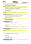
1
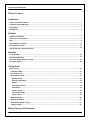
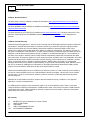
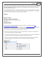
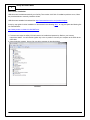
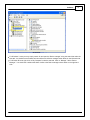
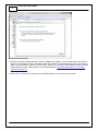
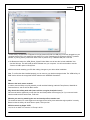
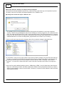
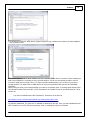
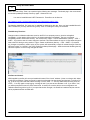
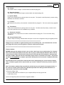
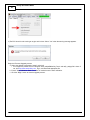
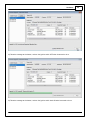
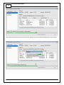
Instruction
Manual
30-71XX
Infinity
Quick Start Guide
STOP!
THIS PRODUCT HAS LEGAL RESTRICTIONS.
READ THIS BEFORE INSTALLING/USING!
THIS PRODUCT MAY BE USED SOLELY ON VEHICLES USED IN SANCTIONED COMPETITION WHICH MAY NEVER BE USED UPON A
PUBLIC ROAD OR HIGHWAY, UNLESS PERMITTED BY SPECIFIC REGULATORY EXEMPTION. (VISIT THE “EMISSIONS” PAGE AT HTTP://
WWW.SEMASAN.COM/EMISSIONS FOR STATE BY STATE DETAILS.)
IT IS THE RESPONSIBILITY OF THE INSTALLER AND/OR USER OF THIS PRODUCT TO ENSURE THAT IT IS USED IN COMPLIANCE WITH
ALL APPLICABLE LAWS AND REGULATIONS. IF THIS PRODUCT WAS PURCHASED IN ERROR, DO NOT INSTALL AND/OR USE IT. THE
PURCHASER MUST ARRANGE TO RETURN THE PRODUCT FOR A FULL REFUND.
THIS POLICY ONLY APPLIES TO INSTALLERS AND/OR USERS WHO ARE LOCATED IN THE UNITED STATES; HOWEVER CUSTOMERS
WHO RESIDE IN OTHER COUNTRIES SHOULD ACT IN ACCORDANCE WITH THEIR LOCAL LAWS AND REGULATIONS.
WARNING: This installation is not for the tuning novice! Use this system with EXTREME caution! The AEM
Infinity Programmable EMS allows for total flexibility in engine tuning. Misuse or improper tuning of this
product can destroy your engine! If you are not well versed in engine dynamics and the tuning of engine
management systems DO NOT attempt the installation. Refer the installation to an AEM-trained tuning
shop or call 800-423-0046 for technical assistance.
NOTE: All supplied AEM calibrations, Wizards and other tuning information are offered as potential
starting points only. IT IS THE RESPONSIBILITY OF THE ENGINE TUNER TO ULTIMATELY CONFIRM IF THE
CALIBRATION IS SAFE FOR ITS INTENDED USE. AEM holds no responsibility for any engine damage that
results from the misuse or mistuning of this product!
AEM Performance Electronics
AEM Performance Electronics, 2205 126th Street Unit A, Hawthorne, CA 90250
Phone: (310) 484-2322 Fax: (310) 484-0152
http://www.aemelectronics.com
Instruction Part Number: 10-7100
Document Build 5/26/2015
Infinity Quick Start Guide
Table of Contents
Introduction
.............................................................................................................................................................
1
Software
Download Notice
1
12.............................................................................................................................................................
Month Limited Warranty
1
Kit.............................................................................................................................................................
Contents
............................................................................................................................................................. 3
Background
Software
.............................................................................................................................................................
4
Software
Installation
.............................................................................................................................................................
5
Device
Driver Installation
............................................................................................................................................................. 8
FAQ
.............................................................................................................................................................
11
Flash
Memory Functions
.............................................................................................................................................................
11
Plot
Data and Control
.............................................................................................................................................................
13
Infinity
Hot Keys - Quick Reference
Hardware
.............................................................................................................................................................
15
Serial
Number
.............................................................................................................................................................
15
Account
Registration
.............................................................................................................................................................
23
Firmware
Update Window Layout
.............................................................................................................................................................
24
Firmware
Update
Tuning Guide
.............................................................................................................................................................
31
Basic
Tuning
Calibration
..........................................................................................................................................................31
Data
Unit
..........................................................................................................................................................32
Preferences
Wizard
..........................................................................................................................................................33
Basic Setup
......................................................................................................................................................33
Wizard
Design
......................................................................................................................................................34
Wizard
Organization
......................................................................................................................................................35
Engine
......................................................................................................................................................36
Tuning
Preferences
......................................................................................................................................................37
Cam/Crank
......................................................................................................................................................39
Injector
Setup
Set......................................................................................................................................................43
Throttle Range
......................................................................................................................................................44
Ignition
Sync
Modified
..........................................................................................................................................................46
Values
Right
..........................................................................................................................................................47
Click Editing
VE
..........................................................................................................................................................47
& Airflow Based Tuning
Target
..........................................................................................................................................................51
Lambda
Wiring, Pinouts and Schematics
© 2015 AEM Performance Electronics
Contents
............................................................................................................................................................. 53
Wiring
Tools
..........................................................................................................................................................54
Idle
..........................................................................................................................................................55
Air Control Valve Requirements
© 2015 AEM Performance Electronics
Infinity Quick Start Guide
1
Introduction
Software Download Notice
The latest Infinity Tuner PC software is available for download at http://www.aemelectronics.com/?q=products/
support/software-downloads.
The latest AEMData analysis software is available for download at http://www.aemelectronics.com/?q=products/
support/software-downloads
The latest firmware for your Infinity ECU is available at http://www.aeminfinity.com. Follow the instructions in this
manual to install InfinityTuner and AEMData (optional) then go directly to aeminfinity.com to download your
firmware.
12 Month Limited Warranty
Advanced Engine Management Inc. warrants to the consumer that all AEM High Performance products will be free
from defects in material and workmanship for a period of twelve (12) months from date of the original purchase.
Products that fail within this 12-month warranty period will be repaired or replaced at AEM’s option, when
determined by AEM that the product failed due to defects in material or workmanship. This warranty is limited to
the repair or replacement of the AEM part. In no event shall this warranty exceed the original purchase price of the
AEM part nor shall AEM be responsible for special, incidental or consequential damages or cost incurred due to
the failure of this product. Warranty claims to AEM must be transportation prepaid and accompanied with dated
proof of purchase. This warranty applies only to the original purchaser of product and is non-transferable. All implied
warranties shall be limited in duration to the said 12-month warranty period. Improper use or installation, accident,
abuse, unauthorized repairs or alterations voids this warranty. AEM disclaims any liability for consequential
damages due to breach of any written or implied warranty on all products manufactured by AEM. Warranty returns
will only be accepted by AEM when accompanied by a valid Return Merchandise Authorization (RMA) number.
Product must be received by AEM within 30 days of the date the RMA is issued.
Please note that before AEM can issue an RMA for any electronic product, it is first necessary for the installer or
end user to contact the EMS tech line at 1-800-423-0046 to discuss the problem. Most issues can be resolved
over the phone. Under no circumstances should a system be returned or a RMA requested before the above
process transpires.
AEM will not be responsible for electronic products that are installed incorrectly, installed in a non-approved
application, misused, or tampered with.
Any AEM electronics product can be returned for repair if it is out of the warranty period. There is a minimum
charge of $50.00 for inspection and diagnosis of AEM electronic parts. Parts used in the repair of AEM electronic
components will be extra. AEM will provide an estimate of repairs and receive written or electronic authorization
before repairs are made to the product.
Kit Contents
1x
1x
2x
1x
10 x
INFINITY ECU (Varies depending on kit part number)
QUICK START GUIDE
USB CABLE
4GB FLASH MEMORY DEVICE
ECU HARNESS TERMINALS
© 2015 AEM Performance Electronics
Introduction
Infinity-8/10/12 Kit Contents
© 2015 AEM Performance Electronics
2
Infinity Quick Start Guide
3
Infinity-6/8h Kit Contents
Background
The Infinity platform is very different from previous generation AEM EMS products. The hardware (circuit board
assembly) is designed around a very advanced automotive grade microcontroller (processor or “chip”). Several
layers of software reside on this chip that allow for real time firmware programming without the need to write
computer code. This technology has allowed AEM to develop advanced control models never before used on other
AEM EMS products. We’ve listened to our customers over the years and have attempted to simplify the tuning
process by employing an airflow based fuel control model eliminating many of the lookup and trim tables from
previous generation ECUs. The look and feel is very different and it may take some time to adjust to the new tuning
environment.
Our new tuning tool, Infinity Tuner is also a brand new product built from the ground up to interface with the new
hardware. It features a modular design that allows users and developers to build completely customized templates
and even design “plug in” applications that can automate many tuning tasks. Unlike previous AEM Setup Wizards
in older products like AEM Pro and AEM Tuner, the Infinity Tuner Setup Wizard “plug in” is a completely standalone application that will evolve with Infinity Tuner. It is much more integrated with the ECU hardware and performs
complex validation checks for all requested changes.
Among other things, Infinity Tuner is a powerful math processor. In addition to supporting standard global units and
© 2015 AEM Performance Electronics
Introduction
4
math functions, special features allow users to create completely custom conversion channels for table data.
Virtually any function can be employed to display data in different formats or units. Math functions are also used for
table edits. ANY MATH function can be used not just a list of pre-defined selections. Advanced users will really
enjoy the flexibility this feature adds.
A built-in logging playback/controls synchronization feature allows tuners to view live plot data and make changes
to their calibration values on the fly, knowing exactly where the ECU was accessing table data. For more detailed
post processing of data, AEM offers its new analysis package, AEMdata.
Software
Software Installation
Minimum computer requirements:
OS - Windows XP with .NET 4.0 framework installed
Ram - 2GB
Processor - 1 GHz
Free HD space - 600 Mb
Connectivity - USB 2.0
All current Infinity Tuner software installations and drivers are available for download from AEM at http://
www.aemelectronics.com/products/support
All current firmware pakgrp files are available for download from AEM at http://www.aeminfinity.com. You must
download and save a valid pakgrp file before proceeding with the firmware update process.
1. Run the setup.exe. Hit Next> and follow the instructions on each page.
2. Read and accept the terms of agreement and pick your desired location for Infinity Tuner to be installed. Hit
Next> and allow the software to complete installation.
3. You may now exit the Infinity Tuner installer. You can now run Infinity Tuner. If this is a brand new installation, to
use Infinity Tuner with an ECU connected you will need to install the necessary drivers.
4. If desired, add a desktop link for InfinityTuner. Click the Windows Start button and navigate to All Programs
\InfinityTuner. Right click on the InfinityTuner link and select Send to>Desktop (create shortcut).
© 2015 AEM Performance Electronics
Infinity Quick Start Guide
5
Device Driver Installation
USB drivers are installed automatically as of Infinity Tuner version 2.95.7043. If installation problems occur, follow
the procedure below to manually install the drivers.
USB drivers are available for download from http://www.aemelectronics.com/products/support
A step by step guide for driver installation is documented in the following video...or copy and paste the following link
into a web browser:
http://www.youtube.com/watch?v=i5AY2MFmnzI
1. For these next steps the Infinity ECU will need to be installed and powered up. Refer to your harness
instructions details. You will need the ignition key in the on position. Connect your computer to the ECU via the
USB cable.
2. Open the device manager. How to find your device manager is described below.
Windows7
© 2015 AEM Performance Electronics
Software
6
WindowsXP
For Windows 7 users you may simply search for and open the “Device manager” using the search bar under the
start tab. You should see a window that looks similar to the Device manager shown above on the left hand side.
For Window XP users right click on “My Computer” under the start tab. Click on “Manage.” Select “Device
Manager.” You should see a window that looks similar to the Device manager shown above on the right hand
side.
© 2015 AEM Performance Electronics
Infinity Quick Start Guide
7
3. Next look for a device labeled something close to “AEM Infinity-10 EMS.” It may be listed under “Other devices.”
Right click “AEM Infinity-10 EMS” and select Update Driver Software. When prompted with “How do you want to
search for driver software?” select the second option, “Browse my computer for driver software Locate and install
driver software manually.” USB driver files can be downloaded from http://www.aemelectronics.com/catalogsoftware-downloads-72/
Save this file in an easy to find location like the Windows Desktop. You will need this link below.
© 2015 AEM Performance Electronics
Software
8
**If AEM Infinity-10 EMS does not appear on the list please verify that the USB plug is securely plugged into your
computer and the ECU. Also make sure that the ECU is in fact powered up and connected correctly. If problem
persists, try turning the key off and then back to the on position or try a different USB port on the PC.
4. Hit Browse and select the “AEM_Drivers_Signed” folder. Make sure to have the “Include subfolders” box
checked. Hit next. This will install the driver software onto your computer. You will now be able to use the
“Connect to USB” option in InfinityTuner.
AEM recommends restarting your PC after making changes to your device driver installation.
Note: To confirm the driver installed properly you can return to your device manager window. The “AEM Infinity-10
EMS” device will now be recognized and fall under the tab “AEM EMS Controllers.”
FAQ
What are the basic sensor needed?
In order to use the Infinity to its full potential you will need the following; Intake Air Temp Sensor, Manifold Air
Pressure Sensor, and an Air/Fuel Ratio sensor.
Why doesn't the Infinity work with (insert vehicle or engine description here)?
We have not had the opportunity to map the Cam and Crank profiles of that engine yet. If your cam and crank
matches another vehicle we do have, it will work.
What do you mean by matching the cam and crank profile to another car?
The number of teeth on a crank trigger and cam trigger let the Infinity know where the engine position is exactly.
Based on that the infinity will know when to spark, and inject fuel.
Will this control my Supra VVTI?
Yes, but in our base VVTI tune the VVTI map is all 0's.
© 2015 AEM Performance Electronics
Infinity Quick Start Guide
9
What is the difference between an Infinity-8 and an Infinity-8h?
The 8h will control 8 high impedance injectors only, while the 8 will control either high or low impedance injectors.
The Infinity 8 also has more inputs and outputs available for use. TC/DBW etc etc.
My Infinity won't connect to my PC. What do I do?
1. This problem may be occurring because the device driver needs to be installed or is not being recognized
correctly. *Before moving forward please verify that the USB plug is securely plugged into your computer and the
ECU. Also make sure that the ECU is in fact on and connected correctly. Once verifying everything is connected
properly you will need to obtain the driver files. Download the driver from http://www.aemelectronics.com/catalogsoftware-downloads-72/. Extract the AEM_Drivers_Signed folder into a location of your choosing.
2. Next you will need to open the device manager. How to find your device manager is described below.
For Windows 7 users you may simply search for and open the “Device manager” using the search bar under the
start tab. You should see a window that looks similar to the Device manager shown above on the left hand side.
For Window XP users right click on “My Computer” under the start tab. Click on “Manage.” Select “Device
Manager.” You should see a window that looks similar to the Device manager shown above on the right hand
side.
3. Next look for a device labeled something close to “AEM Infinity-10 EMS.” It may be listed under “Other devices.”
Right click “AEM Infinity-10 EMS” and select Update Driver Software. When prompted with “How do you want to
search for driver software?” select the second option, “Browse my computer for driver software Locate and install
driver software manually.”
© 2015 AEM Performance Electronics
Software
10
4. Hit Browse and select the “AEM_Drivers_Signed” folder from step 2. Make sure to have the “Include subfolders”
box checked. Hit next.
This should begin to install the driver software onto your computer. Please allow it a moment to finish installing the
driver. Once installation is complete you may close that window. You will now successfully be able to use the
“Connect to USB” option in Infinity Tuner. To confirm the driver installed properly you can return to your device
manager window. The “AEM Infinity-10 EMS” device will now be recognized and fall under the tab “AEM EMS
Controllers.”
While running the Infinity Tuner Wizard Installer it is unable to successfully finish. A message reads “Setup Infinity
Tuner Wizard needs the Microsoft .NET 4.0 Full Framework to be installed. Press OK and Install that first.” What
should I do?
You need to install Microsoft .NET Framework 4. These files can be found at:
http://www.microsoft.com/download/en/details.aspx?displaylang=en&id=17851
The installer “dotNetFx40_Full_setup.exe” is available for download on this site. Once you have installed Microsoft
.NET Framework 4 you may continue using Infinity Tuner or installing the Infinity Tuner Wizard.
© 2015 AEM Performance Electronics
Infinity Quick Start Guide
11
When I first start Infinity Tuner I am experiencing the following error message: “The wizard plug in has encountered
an unknown problem(UI thread). Please try again.” What should I do?
You need to install Microsoft .NET Framework 4. These files can be found at:
http://www.microsoft.com/download/en/details.aspx?displaylang=en&id=17851
The installer “dotNetFx40_Full_setup.exe” is available for download on this site. Once you have installed Microsoft
.NET Framework 4 you may continue using Infinity Tuner or installing the Infinity Tuner Wizard.
Flash Memory Functions
Changes made to calibration tables are stored on the ECU in a temporary memory location and applied
immediately. In other words, while tuning live, all changes take effect immediately. They are not however
immediately saved to ECUs flash memory. The menu function Target – Commit modifications (Hot Key – CTRL +
SHIFT + C) is used to save all current changes to the flash. This feature allows the user to choose what changes to
save to the ECU during a tuning session. Target – Revert modifications (Hot Key – CTRL + SHIFT + R) removes
any changes not previously saved. At key off, the system will automatically commit all unsaved changes if the Key
Off Commit option is checked in the Tuning Preferences Setup Wizard page. AEM recommends disabling the Key
Off Commit options once all tuning changes are made.
Plot Data and Control
AEM supplied layout files will come pre-loaded with several “Plot Control” windows. (Users can always add, delete
or edit them as desired.) These are special controls that allow real time data logging and playback. To begin a PC
log, go to the Log menu and select Start recording or hit the “CTRL + L” hot key. Select Stop recording or hit the
“CTRL + L” hot key again to stop logging. A dialog will ask if you want to save the data or not. If you select “Yes,”
you will be prompted to save the current session file. A session file contains all the current configuration and
calibration data along with a log file. If you open that session file again, the file will be loaded and all plot controls
will be populated with the recorded data.
© 2015 AEM Performance Electronics
Software
12
Plot Window Tools
Selection tool: Choose this icon by clicking on it then left click and drag through the plot window to view
current data values.
Pan tool: Choose this icon by clicking on it then left click and drag through the plot window to pan the data
left or right. Hot Key – Left/Right arrow
Zoom tool: Choose this icon by clicking on it then left click and drag up and down to zoom in and out.
Alternatively, a mouse scroll wheel can be used after selecting the zoom tool. Hot Key – Up arrow/Page up, Down
arrow/Page down
Show legend: Displays or hides the data legend.
Additional hot keys available in plot control window:
Home – Brings you to the start of the log
End – Brings you to the end of the log
For Home and End, the current display range is kept, so if viewing 10 seconds worth of data, Home will display the
first 10 seconds while End will display the last 10 seconds.
Controls Synchronization
When the plot control is populated with data, using the selection tool and dragging through the plot will cause
Infinity Tuner to synchronize all control windows to the plot data. This happens when connected to the simulator
offline or when connected to the ECU via USB. To go back to viewing “live” data, go to the Log menu and select
Goto live data.
© 2015 AEM Performance Electronics
Infinity Quick Start Guide
13
The image above shows plot data sync’d to control windows. All table cursors update with their position relative to
the logged data in the plot control. Note that in this mode, table edits are still possible.
Infinity Hot Keys - Quick Reference
Commonly used Hot Keys.
Action
Default Key
Open saved session
CTRL + SHIFT + O
Save session
CTRL + SHIFT + S
Open layout
CTRL + O
Save layout
CTRL + S
Connect USB
CTRL + SHIFT + U
Disconnect USB
CTRL + SHIFT + D
Go to main window
ESC
Toggle to next control window
TAB
Toggle to previous control window
SHIFT + TAB
Next layout page
CTRL + TAB
© 2015 AEM Performance Electronics
Software
Previous layout page
CTRL + SHIFT + TAB
Start/stop PC logging
CTRL + L
Commit modifications
CTRL + SHIFT + C
Revert modifications
CTRL + SHIFT + R
Select all
CTRL + A
Increase selected cells by 1%
=
Decrease selected cells by 1%
—
Increase selected cells by 5%
SHIFT + =
Decrease selected cells by 5%
SHIFT + —
Increase selected cells by 10%
CTRL + =
Decrease selected cells by 10%
CTRL + —
Add 1 to selected cells
U
Subtract 1 from selected cells
D
Add 10 to selected cells
CTRL + U
Subtract 10 from selected cells
CTRL + D
Smoothing using four neighboring cells
CTRL + 0
Smoothing using eight neighboring cells
CTRL + 1
Simple horizontal interpolation for 2D tables
H
Simple vertical interpolation for 2D tables
V
Simple horizontal interpolation for 1D tables
X
Two-way interpolation using selection corners
C
Two-way interpolation using selection edges
E
Hardware
© 2015 AEM Performance Electronics
14
Infinity Quick Start Guide
15
Serial Number
All Infinity ECUs are serialized. Be sure this identification tag stays intact. Write the number down to be safe.
Infinity ECUs are programmed with cryptographically secure firmware files and each ECU has a unique file set. The
serial number is used to identify the correct files for your ECU.
Account Registration
Note: Hardware part numbers shown in the screen shots below are examples only. Refer to your individual ECU
part number and serial number when filling out registration information.
1) Go to http://www.aeminfinity.com and click on the “Register Here” button.
© 2015 AEM Performance Electronics
Hardware
2) Enter required information and click the “Register” button.
A confirmation email will be sent to the supplied email address. Choose one of the following options:
a. Click on the “click here” link.
b. Or, copy the code and enter it into the Confirmation Code Box.
© 2015 AEM Performance Electronics
16
Infinity Quick Start Guide
17
3) After entering the code, click on the “Confirm” button.
4) Click on the “your account page” to continue with ECU registration; otherwise click the “Log Off” button.
AEM Infinity ECU Registration
1) Go to http://www.aeminfinity.com and log in to your account.
© 2015 AEM Performance Electronics
Hardware
18
2) Click on the “Register New Product” button.
3) Enter the Serial Number and Security Code. Serial Number is found on sticker on ECU case. Security Code is
included in ECU packaging.
© 2015 AEM Performance Electronics
Infinity Quick Start Guide
19
4) Enter Product Registration Information. You must first read and accept the Agreement before completing
registration.
5) Read and then accept Usage Agreement by selecting the “I Agree” button.
© 2015 AEM Performance Electronics
Hardware
6) Click the “Complete Registration” button once the Usage Agreement has been accepted.
Firmware and Configuration Updates
1) Go to http://www.aeminfinity.com and log in to your account.
© 2015 AEM Performance Electronics
20
Infinity Quick Start Guide
21
2) Locate Firmware and Configuration updates. Check for Firmware Updates since last downloaded. Click the
“INFO” button to locate Firmware and Configuration files.
3) Locate the desired Configuration file and click the “Download” button. The Configuration file includes the
Firmware and the Configuration files as a .pakgrp file.
© 2015 AEM Performance Electronics
Hardware
4) Save the .pakgrp file in the AEM Infinity Tuner directory: C:/Program Files (x86)/AEM/Infinity Tuner
© 2015 AEM Performance Electronics
22
Infinity Quick Start Guide
23
Firmware Update Window Layout
Firmware update window layout and definitions
(A) - Available Images
A list of configuration (pakgrp) files compatible with a particular ECU. Each Infinity ECU is unique. Pakgrp
files from one Infinity ECU can not be used on another Infinity ECU. Several pakgrp files are usually available
for each Infinity hardware part number. Selecting one of the items in this list will populate the Image Info
window with the descriptions of all files contained in the pakgrp. Appropriate files for your application
must be downloaded from aeminfinity.com and saved on your PC in order to appear in this list..
(B) - Serial Number
This is a unique hardware identifier number for the ECU. Although they are related, it is not the same as the
ECU serial number included on the serial number sticker.
(C) - Firmware
The version of the firmware on the primary microcontroller in the Infinity ECU. This is not necessarily the
version of the firmware being loaded into the ECU. It is the version being upgraded from. In the example image
above, the firmware version currently loaded on the ECU is 96.7115. The version being loaded into the ECU is
96.8192.
(D) - Peripheral
The Infinity ECU includes two different microcontrollers that require firmware. This is the version of the firmware
loaded into the peripheral microcontroller.
(E) - Location
The directory location of the selected pakgrp file
(F) - Name
The file name of the selected pakgrp file
© 2015 AEM Performance Electronics
Hardware
24
(G) - Images
The number of files or "images" contained within the selected pakgrp file
(H) - Supported Images
The number of valid supported images contained within the selected pakgrp file
(I) - Dynamic Model
Infinity control model files are typically broken into two parts. The dynamic model file primarily contains tuning
table data and calibration constants.
(J) - Firmware
The firmware for the primary microcontroller contained within the pakgrp file. This is the version being upgraded
to.
(K) - Fixed Model
Infinity control model files are typically broken into two parts. The fixed model file primarily contains control
logic math expressions and non-modifiable tuning constants.
(L) - Peripheral Controller
The firmware for the peripheral microcontroller contained within the pakgrp file. This is the version being
upgraded to.
(M) - Keep Calibration Data
Select to keep the existing calibration data and import it into the new configuration during the upgrade process.
**************************************************************************
Pakgrp files are available to registered Infinity users at aeminfinity.com. You must download and save
your pakgrp file before proceeding with the firmware update process below.
**************************************************************************
Firmware Update
BEFORE beginning the update process, be sure to have a saved copy of your tuned session file. If a power
failure occurs during the update process, this is the only way to ensure that the calibration data is not lost.
A power failure at certain critical points in this process could render the ECU inoperative, requiring return
and repair at AEM. Ensure the PC has a full battery charge and/or is connected to AC power. This process
can take UP TO 4 MINUTES to complete, especially if the peripheral microcontroller is updated at the same
time.
If the firmware version on the ECU is older than the version supported by your current version of Infinity
Tuner, a firmware upgrade will be required when you connect. Otherwise, follow the procedure outlined
below.
Note: The firmware update utility is periodically revised and may not match the descriptions below. In
the event of a conflict, please follow the instructions provided in the dialog windows themselves or
supplemental instructions provided by AEM.
1) Connect to Infinity Tuner.
a. Plug the USB cable from the ECU into your computer USB port and key ignition ON.
b. Open Infinity Tuner.
2) Click the Target drop-down list and select “Upgrade firmware…”
© 2015 AEM Performance Electronics
Infinity Quick Start Guide
25
3) The ECU should not be running an engine at this time. Select “Yes” when the warning message appears.
Begin the Firmware Upgrade process.
a. Select the desired Configuration “Image” on the left.
i. If no images are present check C:\Program Files (x86)\AEM\Infinity Tuner\ and verify .pakgrp file is there. If
not, visit http://www.aeminfinity.com, log in, and download appropriate file.
b. Ensure "Keep Calibration Data" check-box is marked to save current calibration.
c. Click the “Begin” button to start the upgrade process.
© 2015 AEM Performance Electronics
Hardware
4) Follow the message at the bottom, and turn the ignition switch OFF when instructed to do so.
5) Follow the message at the bottom, and turn the ignition switch back ON when instructed to do so.
© 2015 AEM Performance Electronics
26
Infinity Quick Start Guide
27
If Keep Calibration Data is checked, the system will upgrade and load all usable calibration data as shown below.
© 2015 AEM Performance Electronics
Hardware
28
Note: at certain points in the process, the Infinity ECU will re-boot and attempt to connect with the PC. The
time it takes to connect might vary for different PCs. If the process appears to hang at this stage, simply
unplug and replug the USB comms connector. Often this will force the PC to re-enumerate the USB port
and connect.
6. When the "Peripheral Control Module image" is updated, a full power reset may be required meaning either the
battery needs to be disconnected and re-connected or all harness connectors need to be removed from the ECU
for at least 5 seconds, then re-connected.
© 2015 AEM Performance Electronics
Infinity Quick Start Guide
29
7. When the message below is displayed, turn the ignition switch back on.
8. When the message at the bottom indicates that it’s safe to close the window, click "X” button on the top right of
the window.
© 2015 AEM Performance Electronics
Hardware
30
Once the update is complete, it's good practice to cycle the ignition switch to reset the hardware. Once that is
done, you can connect and begin monitoring data and/or tuning again. For applications that use a stepper
motor idle valve, it's important that a full power reset be done prior to starting the engine. Turn the key
off and wait at least 20 seconds before starting. This will allow the stepper valve to park and reset.
A firmware update will erase the USB log channel list stored in the ECU memory. This channel list will
need to be reset before USB logging will function correctly. Go to Logging>USB Logging – Channel
Setup. This dialog allows the user to select channels for USB logging. Manually select channels by left clicking
on the check box or alternately by using the arrow keys to scroll through the list and the space bar key to select.
Logging lists can be saved for later use by using the Save button. The Load button will load previously saved lists of
channels. The Append button will append a different list of channels onto the existing list of selected channels.
Note that the list of channels for logging is saved in ECU memory. Channels can't be selected offline. They can
only be selected when connected to an ECU.
© 2015 AEM Performance Electronics
Infinity Quick Start Guide
31
Tuning Guide
Basic Tuning
Calibration Data
Connecting, Saving and Importing Session Data
1) With the Ignition in the ON position and InfinityTuner Running, click on the Connection menu item and select
Connect to USB from the dropdown list. A progress bar will be displayed as the laptop gets the calibration info
from the ECU.
2) Open a layout file by clicking on the Layout menu item and select Open. Layout files have a .itlyt extension and
should be saved in the My Documents\InfinityTuner\Layouts folder.
3) Save the session file by selecting File – Save session. Session files have a .itssn extension and should be
saved in the My Documents\InfinityTuner folder.
The default calibration data provided by AEM should be sufficient to start an engine with similar displacement,
sensor setup, and injectors. Every vehicle must be tuned before use. AEM provided base calibration data is
installed to the My Documents\AEM\Infinity Tuner\Sessions folder. To import calibration data from a saved session
file, go to File > Import calibration data.
Wait a few moments for the operation to complete. Status messages are displayed during the process notifying the
user of each step along the way. If the import function is done while connected to an ECU, after the import is
complete:
1) Turn the key off and wait for the main relay to power down completely. This usually takes about 10 seconds but
depends on the model.
2) Turn the key back on.
Certain applications with CAN dash requirements must be powered down completely and restarted after an import
calibration. If this is not done, error lights may appear on the dash.
Please be aware of cross-platform differences that may require additional attention after importing calibration data.
For instance, the Digital7 pin is available on the Infinity-6 ECU but not available on the Infinity-8H ECU. After
importing Infinity-6 session data to an Infinity-8, any input that was assigned to use Digital7 will be displayed as
invalid in the wizard and needs to be reassigned to work properly.
© 2015 AEM Performance Electronics
Tuning Guide
32
Unit Preferences
The user can select global unit preferences by going to the menu item Wizard > Units Preference...
Choose a global unit system (U.S. or SI) or alternately double click on each unit category and select from available
options as shown below for pressure.
© 2015 AEM Performance Electronics
Infinity Quick Start Guide
33
Wizard Basic Setup
Wizard Design
The ECU setup wizard is designed to simplify the initial configuration of the Infinity ECU. AEM recommends using
the wizard only when connected to the ECU via USB with the power on. Most of the setup wizards require the
engine to NOT be running. Exceptions will be clearly stated in the function descriptions.
The setup wizard contains general and detailed descriptions with each major function. The most imperative
functions are discussed below. Use the descriptions in the wizard to assist in the completion of all other setup
features. New setup wizard features are being added constantly. Please follow the written descriptions on each
wizard page as this document may not accurately represent the features included in the most recent versions.
The Setup Wizard is a stand alone application that runs in conjunction with Infinity Tuner. This software is updated
periodically and its appearance and features may not completely match the descriptions below. In the event of a
conflict, refer to the descriptions and instructions on the Setup Wizard pages themselves.
With the laptop connected to the Infinity ECU via USB and InfinityTuner connected, go to the Wizard menu at the
top of the InfinityTuner layout and select Setup Wizard. Alternately, the hot key combination [ALT]-[w]-[w]-[w] will
launch the setup wizard.
© 2015 AEM Performance Electronics
Tuning Guide
Wizard Organization
The wizard is organized into different sections with expandable menu items on the left hand pane. Use the
highlighted arrow below in each section to expand the available sections.
© 2015 AEM Performance Electronics
34
Infinity Quick Start Guide
35
Engine
Note: This wizard can not be used when the engine is running.
Engine Displacement (L)
Enter the engine displacement in liters.
Min value = 0.250, Max value = 10.0
Number of Cylinders:
Enter the number of cylinders within the engine.
Min value = 1, Max value = 10
Possible values: 1,2,3,4,5,6,8,10
Engine Cycle Type:
Enter the engine type: 2 Stroke or 4 Stroke.
Firing Order:
Select the firing order of the engine.
Airflow Calculation Method:
Select how the airflow calculation is processed. There are 3 options:
VE: This is the default configuration. Airflow is calculated using the speed density algorithm.
0–5V MAF: Airflow is calculated using a 1-axis lookup table that has an analog (0–5V) input from a typical
OEM MAF sensor.
Frequency MAF: Airflow calculated using a 1-axis lookup table that has a digital input from a typical OEM
MAF sensor
© 2015 AEM Performance Electronics
Tuning Guide
36
Main Spark Map Load Axis Selection:
This selection will set the load (y-axis) of the ignition maps. Note: The BaseIgnMap and FlexIgnMap must have the
same load channel.
Load Axis Channels:
MAP [kPa]
Throttle [%]
MassAirflow [gms/s]
MassAirflow [gms/rev]
MAP/EBP
MAP/Baro
VE Table Load Axis Selection:
This is only available if the Airflow Calculation Method is selected. It will set the load (y-axis) of the VE Table.
Load Axis Channels:
MAP [kPa]
Throttle [%]
MassAirflow [gms/s]
MassAirflow [gms/rev]
MAP/EBP
MAP/Baro
DBW_APP1 [%] Filtered
Tuning Preferences
Calibration data is automatically saved to ECU flash memory at key off if the "Key Off Commit" function is selected
in the Tuning preferences wizard page. Proper power sequencing is critical in order to avoid problems. If power is
removed from both pins C1-10 and C2-50 (Infinity 8/10/12 hardware) before this action is completed, the ECU may
become inoperable and require reprogramming at AEM.
© 2015 AEM Performance Electronics
Infinity Quick Start Guide
37
Cam/Crank
Choose the Cam/Crank timing type that will be used. The description field notes important information about edge
selections and wiring requirements.
© 2015 AEM Performance Electronics
Tuning Guide
Additional settings exist to adjust noise cancellation. For more details see Noise Cancellation
© 2015 AEM Performance Electronics
38
Infinity Quick Start Guide
39
Injector Setup
Primary Injector Duty Limit
Limits the maximum duty applied to primary injectors.
Min value = 0, Max value = 100
Number of Injectors
The drop down box allows the user to select the desired Number of Injectors.
Min value = 2, Max value = 12
Has Secondary Injectors
If secondary injectors will be used, select this check box. A new fuel type menu is now visible labeled Fuel Type
(Secondary Injectors).
See Staged Injection for additional tuning information.
© 2015 AEM Performance Electronics
Tuning Guide
40
Note: If secondary injectors are being used, the option Has Secondary Injectors must be selected and the table
must be filled out indicating any injector number greater than the number of engine cylinders as secondary. These
selections must be made before restarting the ECU and closing the form; otherwise an error will occur. See image
below for a typical 6 cylinder engine setup with 6 additional injectors classified as secondary. Note also the option
to select a different fuel type for primary and secondary.
Fuel Type
This drop down menu contains the following setup information for primary (and secondary fuel types, if selected).
-Gasoline
-Ethanol
-Methanol
-E85
-Flex Fuel
Phasing
The default injector phasing for the primary injectors is determined from the Firing Order information from the
Ignition Wizard. There is a fixed offset of 540 for injectors. After this offset is added, the system checks to see if
the result is less than 720. If the result of the calculation is greater than or equal to 720, it is subtracted by 720
from that result
Example:
4 cylinder 1-3-4-2 firing order:
Injector 1 phasing = 0 + 540 (offset) = 540
Injector 3 phasing = 180 + 540 (offset) = 0
Injector 4 phasing = 360 + 540 (offset) = 180
Injector 2 phasing = 540 + 540 (offset) = 360
O2 Feedback
Lambda sensor assignment is determined by assigning a value of 1 or 2 to the InjXLambdaFB channels. A value of
1 will assign the Lambda 1 sensor and a value of 2 will assign the Lambda 2 sensor. Min value = 1, Max value = 2
© 2015 AEM Performance Electronics
Infinity Quick Start Guide
41
Fuel Pressure Regulator Reference
Allows the user to choose the proper reference pressure for the fuel pressure regulator. The drop down menu has
the following options:
Manifold Vacuum Reference: This should be selected if the fuel pressure regulator's port is connected to a
vacuum or vacuum/boost source.
Atmospheric Reference: This should be selected if the fuel pressure regulator's port is open to atmosphere or if a
dead end fuel system is used where fuel pressure is constant.
© 2015 AEM Performance Electronics
Tuning Guide
42
Primary Injector Flow Selection
This database allows the user to select proper primary injector flow data.
InjFlowRate [cc/sec], 1-Axis lookup table of flow vs injector pressure.
InjOffset [us/10], 2-Axis lookup table of PW offset vs battery voltage and injector pressure
Secondary Injector Flow Selection
If Secondary Injectors were selected in the Injector Setup Wizard, this Secondary Injector Flow Selection database
will be enabled. This allows the user to select proper secondary injector flow data.
InjSecFlowRate [cc/sec], 1-Axis lookup table of flow vs injector pressure.
InjSecOffset [us/10], 2-Axis lookup table of PW offset vs battery voltage and injector pressure
© 2015 AEM Performance Electronics
Infinity Quick Start Guide
43
NOTE: If the Setup Wizard does not contain your specific fuel injector type, you can modify the InjFlowRate table
manually. If you do not know the different flow rates at different fuel pressures, choose a flow rate (based on
Manufacturers specs) at a known pressure and populate the entire row with that value. For example, you have a
fuel injector that is not listed in the Wizard Selection. You know that it flows 475 cc/min at 45 psi. Select the cells
in the upper row of the InjFlowRate [cc/min] table and manually input 475. This will suffice to get the car up and
running, though proper flow data is ideal.
Set Throttle Range
The wizard displays a warning message to the user if the software is not connected to a hardware
target.
Live TPS Volts
Text and graphical representation of the raw analog voltage is shown.
© 2015 AEM Performance Electronics
Tuning Guide
44
Steps
Set TPS Volts Min
Press this button when the throttle pedal is fully released. This will write the current value of Analog7 [V] to
the Throttle_raw [%] Analog In conditioner and display the resultant value on the TPS Min Volts: X.XX
display.
Set TPS Volts Max
Press this button after the throttle pedal is fully depresses. This will write the current value of Analog7 [V] to
the Throttle_raw [%] Analog In conditioner and display the resultant value on the TPS Max Volts: X.XX
display.
Ignition Sync
The engine's ignition timing must be synchronized with the Infinity Tuner's ignition timing display. This is crucial
with older vehicles that have adjustable distributors, adjustable cam angle sensors, etc. Most modern engines do
not utilize a manual adjustment for ignition timing. However, this wizard should always be used for verification as
sensors can be frequently installed backwards or upside down. This can catch a problem before damage occurs.
Note: This wizard can only be used when the engine speed is greater than 50 RPM. The ignition timing
will automatically unlock when the window is closed reverting back to the normal calculated value.
© 2015 AEM Performance Electronics
Infinity Quick Start Guide
45
Ignition Timing
For synchronizing, the ignition timing can be locked by checking the box.
Allowable values: Min value = 0, Max value = 45
Sync Adjustment
The window includes 4 buttons. Two buttons are used to Advance Timing and TWO buttons are used to
Retard Timing.
The button labeled Large edits the CamSyncAdjustment TrigOffset [degBTDC] channel in 1.0 deg steps. The
range is 0 to 719 degrees. The button labeled Small edits the TrigOffset [degBTDC] channel in 0.1 deg
steps.
The TrigOffset [degBTDC] is adjustable by Resolution. The Resolution setting has a range of 0.25 deg to 2.0
degrees in 0.25 degree increments. This “stepping” function allows the user to make TrigOffset [degBTDC]
adjustments with the Small button up to the range limit.
Advanced Setup
Pickup sensor delay
The More and Less buttons increase/decrease the SpkDelayComp [us] value in increments/decrements of
5.
Min value = 0, Max value = 500
Two separate procedures are required depending on the Infinity application: Plug and Play or Universal Application.
Plug and Play
a. In the Ignition Sync wizard, select the checkbox “Lock ignition timing at” and set the “degrees BTDC” (10.0 deg
BTDC is the default).
b. Start the engine and use a timing light to verify that the crankshaft timing matches the locked ignition timing
set point (10.0 deg BTDC if using the default setting).
c. If there is a deviation between the locked set point and the actual timing observed with the timing light, use the
Sync Adjustment arrows to match the wizard-displayed value with the actual value. As the Sync Adjustment
arrows are advanced or retarded, the timing observed on the crankshaft will change, while the “Lock ignition
timing at 10.0 degrees BTDC” will remain constant.
Universal Application
a. In the Ignition Sync wizard, select the checkbox “Lock ignition timing at” and set the “degrees BTDC” (10.0 deg
BTDC is the default).
b. Do NOT attempt to start the engine. Disable (unplug) the fuel injectors and/or fuel pump.
c. While cranking the engine, use a timing light to verify that the crankshaft timing matches the locked ignition
timing set point (10.0 deg BTDC if using the default setting).
d. If there is a deviation between the locked set point and the actual timing observed with the timing light, use the
Sync Adjustment arrows to match the wizard-displayed value with the actual value. As the Sync Adjustment
arrows are advanced or retarded, the timing observed on the crankshaft will change, while the “Lock ignition
timing at 10.0 degrees BTDC” will remain constant.
e. Reconnect the fuel injectors and fuel pump.
f. Once the remaining Setup Wizards have been configured, repeat the Ignition Sync process with the engine
running to ensure that the crankshaft timing matches the locked ignition timing set point.
© 2015 AEM Performance Electronics
Tuning Guide
46
Modified Values
Calibration table changes that haven't been committed to flash memory are highlighted as shown below. Conditions
that will reset the display are as follows:
1. Manually committing changes through the Target > Commit modifications menu command
2. Manually committing changes using the hot key combination [Ctrl Shift C]
3. Opening and closing the Setup Wizard. Note the Setup Wizard automatically commits ALL changes to memory
every time it is closed.
4. Turning the ignition switch off when the tuning preference Key Off Commit is selected
© 2015 AEM Performance Electronics
Infinity Quick Start Guide
47
Right Click Editing
To use the right click menu for editing table values, select a portion of the table and right click. Choose from
available options.
VE & Airflow Based Tuning
The Infinity ECU uses significantly different methods of calculating the fuel delivery requirements and outputs than
previous AEM products.
Measured data from sensors, i.e., Manifold Absolute Pressure (MAP [kPa]), Air Temperature, Coolant
Temperature, and Engine RPM, are acquired. The ECU uses this sensor data in combination with Volumetric
Efficiency (VE%) to estimate airflow.
The Volumetric Efficiency is a percentage of air and fuel that actually enters the cylinder during induction relative to
the volumetric capacity (rated displacement) of the cylinder under static conditions. The VE lookup table is a 2-axis
lookup table, with load values (typically MAP [kPa]) versus Engine RPM. In each table cell, the Engine RPM
corresponds with a specific MAP [kPa], and a Volumetric Efficiency is defined for that cell.
© 2015 AEM Performance Electronics
Tuning Guide
48
The Volumetric Efficiency is combined with temperature sensor data to estimate a compensated Mass Airflow. The
ChargeTempBlend table dictates what ratio of air temperature to coolant temperature is used at specific Engine
RPM to adjust the density of the inducted air. A higher number gives priority to Coolant Temperature, and is seen
at lower Engine RPM.
Once Mass Airflow has been calculated using the tables above, the Infinity ECU will look up the Target Lambda
(AFR) and then calculate the fuel requirements. Target AFR will be used as a main parameter in determining fuel
injector flow rate. The LambdaTargetTable (below Left) and AFR Target Table conversion table (below Right) will
have default values. Based on the calculated Mass Airflow, the Infinity ECU will attempt to add enough fuel to hit
the target AFR.
Note: The calculated LambdaTarget influences the fuel delivered to the engine at all times, even when closed-loop
02 feedback is disabled.
© 2015 AEM Performance Electronics
Infinity Quick Start Guide
49
The suggested tuning method is to set the AFR using the LambdaTargetTable or AFR Target Table to a value safe
and suitable for the engine. For normally aspirated engines a value of 13.0:1 or 0.887 lambda is usually sufficient at
all operating conditions. For boosted applications, the operating conditions dictate a safe AFR. Please consult a
tuner knowledgeable in your engine’s requirements for help. Once the target lambda (AFR) values are chosen, run
the engine at as many operating conditions as possible and adjust the VE Table to reach the AFR Target Table
values. Once the VE Table has been tuned to accurately reach the AFR Target Table values at all operating
ranges, then you can change the AFR Target Table to use different AFR settings later. Never adjust VETable to run
a different AFR, only to achieve the LambdaTarget value.
The Injector Flowrate is very important in determining the fuel requirements. The Infinity ECU uses actual Injector
Flowrate [cc/min] to determine the proper injector pulse width. The InjFlowRate [cc/min] table is calibrated from the
Setup Wizard: Injector Flow, however the table can be modified manually for unlisted injectors.
© 2015 AEM Performance Electronics
Tuning Guide
50
Now that the base injector flow rate has been determined, the Infinity ECU applies a few more compensating
factors. Wall Wetting is a function of fuel condensing in the intake manifold at the injection point. At different rates
of change in the MAP [kPa] values, and at different Coolant Temperatures, fuel enrichment compensations are
used to prevent lean and rich conditions during rapid manifold pressure changes. Note that this table has several
different functions. It can be used for dynamic transients by nature of its “MAP Rate” x-axis. It can also be used for
more steady state compensations by adjusting the values in the “middle band” of the table where MAP rate
changes are very small. Positive numbers in this table will effectively add fuel to enrichen the mixture. Negative
numbers have the opposite effect.
The X and Y axis inputs of the WallWetting table can be set to several different variables. These settings are found
in the Setup Wizard page for Accel and Decel Fuel. Axis selections include:
Map Rate
Throttle Rate
Coolant Temp
MAP [kPa]
EngineSpeed [RPM]
DBW_APP Rate
© 2015 AEM Performance Electronics
Infinity Quick Start Guide
51
LamdaAfterStartTrim is a 2-axis table that is used to modify the Lambda (AFR) for specified time after starting
the engine. This table adds a lambda offset for a small period of time after the engine is started. By allowing a
slightly richer mixture target, it will keep the engine from stalling or running rough immediately after starting and the
lambda correction to a minimum. The last column should be populated with “0” trim at operating temperatures to
prevent a continuous lambda offset.
Target Lambda
To control the engine's fuel delivery system, the Infinity can be programmed to run open loop and/or closed loop O2
feedback. Closed loop uses feedback from the oxygen sensor to make temporary, but immediate, corrections to
the injection to maintain a target air fuel ratio (AFR) or lambda. The type of the O2 sensor will determine how
lambda target can be controlled. Due to the nature of standard narrow band O2 sensors, the only accurate
measurement that can be maintained in closed loop is Lambda 1.0. However, wideband O2 sensors can be used in
almost every feedback condition.
© 2015 AEM Performance Electronics
Tuning Guide
52
Note that 14.64:1 is called the stoichiometric AFR for gasoline. It is the ratio where all available fuel is burned
completely. For most performance applications, it is not the ideal AFR to operate the engine at all the time nor is it
the AFR that creates the most power or even economy under all conditions.
When the fuel system is open loop, the O2 sensor is ignored and the injector pulse width relies on the VE Table
and fuel compensators to adjust injection duration. Open loop is necessary during engine starts, when the O2
sensor has cooled below its operating temperature. It may also be necessary when coolant temperatures are low.
In this state, the fuel vaporization is poor and the engine will require a richer mixture to properly operate. When
under heavy load, the engine typically requires an air fuel ratio that is out of a narrow band oxygen sensor's
standard range and open loop will be necessary. When the accelairflow function is triggered during hard
accelerations, open loop may be necessary to help stabilize the Target Lambda. Also, when the deceleration
function cuts fuel completely, target lambda will not be necessary.
LambaTargetTable
Units: Engine Load vs Engine Speed vs Lambda
Description: This table sets the target lambda for various engine conditions.
Tuning Target Lambda
The first step before tuning:
1.
2.
3.
4.
5.
Open Infinity Tuner and connect to the ECU.
Open the Lambda Tab and confirm the Lambda1Cal Table is set up for the oxygen sensor used.
Open the Lambda Control Wizard and check the Lambda 1 Feedback Enable and/or Lambda
Feedback Enable boxes.
Set the Lambda Feedback Max Speed. Wideband O2 sensors are accurate in most situations so this can
be activated all the time, if need be.
Set the Lambda Feedback After Start Delay (typical –10 seconds).
The Infinity Tuner functions are located in the TargetLambda tab.
1.
2.
Use the Lambda Control Proportional Gain by itself and set the Lambda Control Integral Gain and
Lambda Control Derivative Gain to zero.
Log the channels Lambda1 (or 2) and ErrorLambda1 (or 2).
© 2015 AEM Performance Electronics
Infinity Quick Start Guide
53
3.
4.
5.
6.
Increase the Lambda Control Proportional Gain until the point of instability or a sustained oscillation is
reached.
From here, the ultimate proportional (Ku) is found.
From the log, measure the period of oscillation from peak to peak, in seconds, to obtain the critical time
constant or ultimate period (Pu).
Once the values for Ku and Pu are obtained, the PID parameters can be calculated from the following
equations.
Proportional, Integral, and Derivative Feedback
Lambda Control Proportional Gain = 0.60 (Ku)
Lambda Control Integral Gain = 2 (Kp) / Pu
Lambda Control Derivative Gain = (Kp)(Pu) / 8
Note that these values are not optimal values and additional fine tuning may be required to obtain the best target
lambda performance.
Wiring, Pinouts and Schematics
Wiring
© 2015 AEM Performance Electronics
Wiring, Pinouts and Schematics
54
Tools
AEM recommends using the following proper crimp tool for all Infinity ECU terminations, Molex Part No: 638114200. This tool is available in many places. One is shown below. Web address: http://www.newark.com
© 2015 AEM Performance Electronics
Infinity Quick Start Guide
55
A cheaper, but lower quality, alternative is the following crimp tool, Molex Part No: 63811-1000. This tool is
available in many places. One is shown below. Web address: http://www.newark.com
Idle Air Control Valve Requirements
Many Toyota, Mitsubishi, and other vehicles use an Idle Air Control Valve with a Unipolar Stepper Motor (6-pin
connector) and MUST be modified. See picture below. A Bipolar Stepper Motor (e.g., GM) will have a 4-pin
connector and DOES NOT need to be modified. *This info does not apply to vehicles that utilize IACV solenoids.
© 2015 AEM Performance Electronics
Wiring, Pinouts and Schematics
56
The 2 center pins (Black-Red wires) supply 12V power to the stepper motor in the factory setup, however these
pins MUST BE DISCONNECTED before powering on the AEM Infinity ECU.
Step 1: Disconnect connector from IACV housing and gently remove the retainer from the connector.
© 2015 AEM Performance Electronics
Infinity Quick Start Guide
57
Step 2: Use a small flat-blade screwdriver/pick to move the terminal locks while pulling the Black-Red wires out
from the backside of the connector.
Step 3: Use heat shrink to insulate both 12V wires and then zip-tie the insulated wires to a nearby loom.
© 2015 AEM Performance Electronics
Wiring, Pinouts and Schematics
Step 4: Reinstall the retainer, and then plug the connector back into the IACV.
© 2015 AEM Performance Electronics
58