1
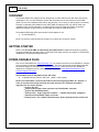
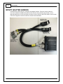
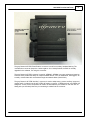
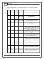
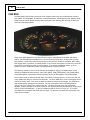
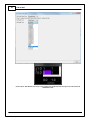
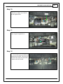
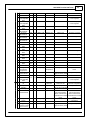
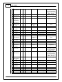
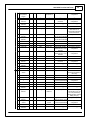
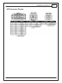
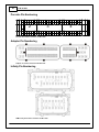
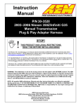
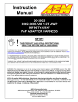
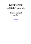
Instruction
Manual
P/N 30-3902
2001-2005 Porsche 996 Turbo
Manual Transmission
Plug & Play Adapter Harness
STOP!
THIS PRODUCT HAS LEGAL RESTRICTIONS.
READ THIS BEFORE INSTALLING/USING!
THIS PRODUCT MAY BE USED SOLELY ON VEHICLES USED IN SANCTIONED COMPETITION WHICH MAY NEVER BE USED UPON A
PUBLIC ROAD OR HIGHWAY, UNLESS PERMITTED BY SPECIFIC REGULATORY EXEMPTION. (VISIT THE “EMISSIONS” PAGE AT HTTP://
WWW.SEMASAN.COM/EMISSIONS FOR STATE BY STATE DETAILS.)
IT IS THE RESPONSIBILITY OF THE INSTALLER AND/OR USER OF THIS PRODUCT TO ENSURE THAT IT IS USED IN COMPLIANCE WITH
ALL APPLICABLE LAWS AND REGULATIONS. IF THIS PRODUCT WAS PURCHASED IN ERROR, DO NOT INSTALL AND/OR USE IT. THE
PURCHASER MUST ARRANGE TO RETURN THE PRODUCT FOR A FULL REFUND.
THIS POLICY ONLY APPLIES TO INSTALLERS AND/OR USERS WHO ARE LOCATED IN THE UNITED STATES; HOWEVER CUSTOMERS
WHO RESIDE IN OTHER COUNTRIES SHOULD ACT IN ACCORDANCE WITH THEIR LOCAL LAWS AND REGULATIONS.
WARNING: This installation is not for the tuning novice! Use this system with EXTREME caution! The AEM
Infinity Programmable EMS allows for total flexibility in engine tuning. Misuse or improper tuning of this
product can destroy your engine! If you are not well versed in engine dynamics and the tuning of engine
management systems DO NOT attempt the installation. Refer the installation to an AEM-trained tuning
shop or call 800-423-0046 for technical assistance.
NOTE: All supplied AEM calibrations, Wizards and other tuning information are offered as potential
starting points only. IT IS THE RESPONSIBILITY OF THE ENGINE TUNER TO ULTIMATELY CONFIRM IF THE
CALIBRATION IS SAFE FOR ITS INTENDED USE. AEM holds no responsibility for any engine damage that
results from the misuse or mistuning of this product!
AEM Performance Electronics
AEM Performance Electronics, 2205 126th Street Unit A, Hawthorne, CA 90250
Phone: (310) 484-2322 Fax: (310) 484-0152
http://www.aemelectronics.com
Instruction Part Number: 10-3902
Document Build 11/4/2015
2
P/N 30-3902
OVERVIEW
The 30-3902 AEM Infinity Adapter Kit was designed for the 2001-2005 Porsche 996 Turbo with manual
transmission. This is a true standalone system that eliminates the use of the factory Porsche DME
(ECU). The use of this adapter makes the kit “plug and play” so no cutting or splicing wires is necessary.
The base configuration files available for the Infinity EMS are starting points only and will need to be
modified for every specific application. Included in these instructions are descriptions of important
differences between using the factory Porsche DME and using the AEM Infinity ECU.
The available AEM Infinity EMS part numbers for this adapter kit are:
30-7109 INFINITY-8
NOTE: The Porsche Infinity-8 EMS has 6 ignition coil outputs and 10 injector outputs.
GETTING STARTED
Refer to the 10-7100 for EMS 30-7100 Infinity Quick Start Guide for additional information on getting
the engine started with the Infinity EMS. Porsche 996 Turbo base sessions are located in C:\Documents
\AEM\Infinity Tuner\Sessions\Base Sessions
DOWNLOADABLE FILES
Files can be downloaded from www.aeminfinity.com. An experienced tuner must be available to configure
and manipulate the data before driving can commence. The Quick Start Guide and Full Manual describe
the steps for logging in and registering at www.aeminfinity.com. These documents are available for
download in the Support section of the AEM Electronics website: http://www.aemelectronics.com/
products/support/instructions
Downloadable files for 2001-2005 Porsche 996 Turbo
7109-XXXX Infinity-8 Porsche 996 Turbo (XXXX = serial number)
NOTE: The Flash Enable connector (described in the following pages) MUST be “jumped” in
order to connect to the Infinity and load the initial firmware file. Subsequent firmware
upgrades will not require this step.
Ignition key OFF
Insert zip-tied jumper shunt connector into Flash Enable connector
Ignition key ON (RUN position)
Infinity Tuner | Target | Upgrade Firmware… | Upload downloaded .pakgrp file
Disconnect Flash Enable jumper connector
Infinity Tuner | File | Import Calibration Data | Select appropriate base session file
© 2015 AEM Performance Electronics
2001-2005 Porsche 996 Turbo
INFINITY CONNECTORS
The AEM Infinity EMS uses the MX123 Sealed Connection
System from Molex. AEM strongly recommends that users
become familiar with the proper tools and procedures for
working with these high density connectors before
attempting any modifications. The entire Molex MX123
User Manual can be downloaded direct from Molex at:
http://www.molex.com/mx_upload/family//
MX123UserManual.pdf
© 2015 AEM Performance Electronics
3
4
P/N 30-3902
INFINITY ADAPTER HARNESS
Included with the 996 Turbo kit is a harness and adapter interface. These are used to make the
connection between the AEM Infinity EMS and the Porsche wiring harness plug and play. This is
depicted below with the 73-pin and 56-pin connectors and the Porsche 996 Turbo header. There are also
a few other integrated connectors within this harness described below.
© 2015 AEM Performance Electronics
2001-2005 Porsche 996 Turbo
5
The gray Deutsch 2P DTM “Flash Enable” connector is used for secondary hardware flashing. The
included shunt connector jumps the 2 wires together. Once initially flashed, the EMS is normally
upgraded in the software, not using this connector.
The gray Deutsch 4P DTM connector is used for “AEMNet”. AEMNet is an open architecture based on
CAN 2.0 which provides the ability for multiple enabled devices, such as dashboards, data loggers, etc.,
to easily communicate with one another through two twisted cables (CAN+/CAN-).
The gray Deutsch 12P DTM “Auxiliary” connector is used to adapt many common ancillary inputs and
outputs easily. Included in the kit are a DTM 12P mating connector, 12 DTM terminals, and a DTM 12P
wedgelock. If used, these components will need to be terminated by the installer or end user with 16–
22awg wire (not included). Note: the pin numbering is molded into the connector.
© 2015 AEM Performance Electronics
6
P/N 30-3902
Below is a description of each of the available input/output found in the Porsche 996 Turbo specific
“Auxiliary” connector.
Deutsch Destination
Pin
Default Pin
Notes
Pin
Pin
Description
Function
1
A1-31
Sensor
Isolated sensor This is not the same as a power ground or chassis
Ground
ground
ground.
2
A1-29
+5V Ref
5 volt sensor
reference supply
When measured with a voltmeter, it is normal to
not measure exactly 5V.
3
A1-3
4
C1-37
Analog 9
Fuel Pressure
This wire goes directly to the signal wire of the
pressure sensor.
5
C1-36
Analog 8
MAP
6
C1-40
Analog 12
Mode Switch
This should be wired directly to the MAP sensor's
signal pin. Note: The OEM Porsche boost
pressure sensor connection must be removed
if adding an external MAP sensor.
This analog input can be used for other functions
such as launch boost target, 2 step, and start
enable.
7
C1-26
Digital 5
Flex Fuel
8
C1-44
Highside 0
Not Assigned
9
C2-15
Analog
Temp 4
10
C2-43
Lowside 8
Not Assigned
This lowside output can be used to activate the
lowside of a relay or PWM a +12V solenoid.
11
C1-25
Digital 4
Not Assigned
This frequency/duty input can be used as flex
content sensor, turbo speed sensor, MAF sensor,
or a wheel speed/vehicle speed sensor.
+12V From
12 volt power This 12V is coming through the vehicle's main relay
Relay
supply from relay
and should only be used for low current
electronics.
This frequency/duty input can be used as flex
content sensor, turbo speed sensor, MAF sensor,
or a wheel speed/vehicle speed sensor.
For a relay, this should be wired to terminal 86 (or
85). Supply chassis ground to the opposite
terminal 85 (or 86). If directly driving a low current
component, wire this to the 12V terminal. 4 amps
max current.
Charge Out Temp
This analog input can be used for temperature
sensors only.
© 2015 AEM Performance Electronics
2001-2005 Porsche 996 Turbo
12
C2-37
© 2015 AEM Performance Electronics
Digital 6
Not Assigned
7
This switch input can be used as a clutch switch,
brake switch, staged switch, nitrous switch, A/C
request switch or as a start enable option.
8
P/N 30-3902
AIRFLOW METERING
The Porsche 996 Turbo is equipped with one MAF (Mass Air Flow) sensor and a pre-throttle body charge
pressure sensor. The Infinity supports the factory mass airflow sensor and boost pressure sensor.
Users can also add a MAP (Manifold Absolute Pressure) sensor and use the speed density airflow
algorithm instead.
Note: If adding an external MAP sensor, users must disconnect the electrical connection from
the OEM Porsche boost pressure sensor to the Infinity.
Mass Airflow Setup
Setup Wizard
To enable MAF on the Infinity, use the setup wizard's "Engine" tab to select "0-5V MAF" or "Frequency
MAF" as the airflow calculation method. Users can choose a number of options for the main spark map
load axis. The example below shows "MassAirflow [gms/rev]" as the main spark load axis. The 996
Turbo base calibration will have this pre-configured for use on a stock 996 Turbo.
© 2015 AEM Performance Electronics
2001-2005 Porsche 996 Turbo
9
Enable the MAF sensor and choose input options in the setup wizard's "Mass Airflow" tab. The MAF
failsafe option can also be enabled here. The 996 Turbo base calibration will have this pre-configured for
use on a stock 996 Turbo.
Note: Users have the option of using either MAP [kPa] or Mass Airflow [gms/rev] (and in some
cases, Throttle [%]) for options requiring an engine load. This includes ignition timing tables,
lowside tables, lean protect tables, wall wetting tables, fuel trim tables, ignition trim tables,
injector timing tables, staged fuel tables, VVC target tables, lambda target tables, nitrous
activation, lambda feedback enable activation, decel fuel cut activation, etc. It is up to the
user to determine which load reference to use in all cases.
© 2015 AEM Performance Electronics
10
P/N 30-3902
Starting
Because there is little mass flow initially during cranking, the Infinity uses a look-up table during engine
cranking (<400 RPM) to determine fuel requirements. This 2D Table is called "CrankMAF_Table [gms/
rev]" and the Infinity will calculate mass airflow (grams/second) based on this grams/rev input. As shown
in the example below, a "clear flood" function can be built into this table (>90% throttle shown).
As the transition from engine cranking to engine running occurs (at 400 RPM), the Infinity switches from
the "CrankMAF" look-up fueling method mentioned above to the MAF sensors. The smoothness of this
transition can be maximized by using the 2D table "FuelTrim_Coolant" to add some initial fuel for a
fraction of a second after the transition occurs, as shown below.
© 2015 AEM Performance Electronics
2001-2005 Porsche 996 Turbo
11
Fuel Tuning
Fuel tuning with MAF sensors uses the two 30-cell 2D tables below called "MAF1_Cal [gms/s]" and
"MAF2_Cal [gms/s]". When two MAF sensors are enabled, these tables are added together to
determine fuel requirements. The 996 Turbo only has one MAF sensor so only "MAF1_Cal [gms/s]" is
used The VE table is not used when MAF is enabled. The factory UEGO sensors are supported and
the AEM adapter harness is wired to use them.
© 2015 AEM Performance Electronics
12
P/N 30-3902
Tuning Ignition Timing
Unless users are using an external (non factory) MAP sensor plumbed into the intake manifold, it is
recommended that users do not use "MAP [kPa]" as an engine load input into the Ignition table. This is
because the OEM Porsche boost pressure sensor is located before the throttle blade and will not
register manifold vacuum. The AEM 996 Turbo base calibration is configured to use the OEM boost
pressure sensor and the main ignition map load axis is "MassAirflow [gms/rev]" as shown below.
© 2015 AEM Performance Electronics
2001-2005 Porsche 996 Turbo
13
MAF Filter
Tuning the MAF filter properly plays an important role for large transient throttle changes. If throttle angle
is quickly increased to wide open from a low throttle angle, high manifold vacuum condition, air mass fills
the intake manifold (nearly equalizing pressure to atmospheric) at a quicker rate than is consumed by
the engine (this is more prominent at lower RPM). Without filtering, this would result in poor (over)
fueling. The example below shows higher filtering during quick throttle open events to combat over
fueling and a lower filter for throttle closing events to allow for maximum decel fuel cut response.
MAF Failsafe
In the event of a sensor/wiring fault (MAF sensor input less than 0.05V or greater than 4.95V), the
"ErrorMAF" channel will toggle from 0 to 1. If the MAF Failsafe Enable is active (configurable in the
wizard's "Mass Airflow" tab), the system will use the 2D "MAF_Failsafe [gms/rev]" look-up table to
calculate airflow instead of using the MAF sensor. Users can choose between Throttle [%] and MAP
[kPa] as a load axis. Users can enable the lean protect function in the setup wizard for further engine
safety.
© 2015 AEM Performance Electronics
14
P/N 30-3902
DRIVE-BY-WIRE THROTTLE CONTROL
The Porsche 996 Turbo uses a single throttle body controlled via drive-bywire (DBW). It is important to note that throttle control is a critical system
which needs to be correct. The basic terms of drive-by-wire are as follows:
the ‘gas pedal’ inside the passenger cabin is called the Accelerator Pedal
(DBW_APP1%), while the electronically controlled throttle in the engine
bay is referenced as ‘Throttle’ (Throttle%, DBW1_TPSA%). Based on the
measured Accelerator Pedal position, the ECU determines a desired
DBW_Target position and moves the Throttle to that position.
As shown, there is a Drive By Wire Wizard which must be used to calibrate accelerator pedal and
throttle position sensors. Although sensor calibration values from one vehicle may be close enough to
work for another vehicle under some circumstances, it is absolutely necessary to run the Drive By Wire
Wizard before running the engine for the first time. The wizard should be repeated if any components in
the throttle control system are removed or replaced such as the throttle bodies, TPS sensors, electronic
throttle control motor, or accelerator pedal.
Please ensure the vehicle’s battery is fully charged (at least 12.6 Volts) before running the Drive By Wire
Wizard, as low battery voltage can result in abnormal sensor measurements. If a battery charger is
available, it is preferable to connect the battery charger in 5A, 10A, or 20A mode and perform the Drive
By Wire Wizard while the battery voltage is near 13.5–14.0 Volts. When connected to the Infinity EMS
with the engine OFF, go to Wizards | Drive By Wire Wizard. Follow the step-by-step instructions for
each page.
© 2015 AEM Performance Electronics
2001-2005 Porsche 996 Turbo
15
The 1D ModeSelect_DBW table is used to switch between the two different DBW_ThrottleCurve tables,
depending on the status of the MODESWITCH function. Both 2D tables use accelerator pedal position
for the y-axis and RPM for the x-axis. The values that are entered in the table are throttle position targets
(example shown below).
Note: There is also a DBW Tuning section in the Wizards | Setup Wizard | DBW Tuning… These
settings can be used to fine tune DBW response.
© 2015 AEM Performance Electronics
16
P/N 30-3902
There are a few integrated DBW fail safes incorporated into the Infinity system. The ECU constantly
monitors the accelerator pedal sensor voltage and throttle position sensor voltages to ensure the signals
are not excessively high or low due to damaged sensors, short circuits, or broken wires. The ECU also
performs self-diagnostics to ensure the electronic throttle is following desired DBW_Target properly, that
the DBW throttle control motor is not using excessive energy to move the throttle, and watching to see
that all the redundant sensors are working together as expected. If any of these conditions are
determined to be abnormal or unsafe, the ECU can shut the engine down to prevent unintended engine
acceleration. This error will reset when the ignition key is cycled.
© 2015 AEM Performance Electronics
2001-2005 Porsche 996 Turbo
17
CRUISE CONTROL
Currently, a cruise control feature is not supported with the AEM Infinity. However, the multi-functional
steering wheel buttons are transmitted over the Porsche CAN bus and are available for miscellaneous
purposes described below. There are 4 buttons: Enable, Cancel, Set, Accelerate+, and Decelerate- (as
shown).
Note: Cruise enable (channel "CC_Enable") must be active (indicated by an illuminated green
cruise light on the dash) for the below features to be functional. To activate "CC_Enable",
simply turn cruise control on (press the outer button on the cruise multifunction switch in once).
Cancel
Users can configure the Cancel button to either the 3-step rev limiter or be an AEM traction control
switch. It is not recommended to use the Cancel button for both of these functions simultaneously. This
switch channel is called “CC_Cancel”.
A 3-step rev limiter is a simplified traction control based system that uses engine and vehicle speed or
launch timer inputs to limit the RPM of the engine. If using the Cancel button as a 3-step rev limiter
switch, first be sure the 3StepSwitch table is set to recognize the “momentary” Cancel button, as shown
in figure 1. Set the 3StepTargetFuel and/or the 3StepTargetSpark table’s first (0 MPH) cell to the desired
launch RPM. When the Cancel button is held down, the EMS will limit the engine’s corresponding RPM.
Once the car is launched and the EMS begins to register vehicle speed, the RPM limit can then be
tailored to prevent wheel spin using these tables.
If using the Cancel button as a traction control switch, the latching Cancel button changes the
TC_SlipTargetTrim 1-axis lookup table, as shown in figure 2. Simultaneously, the low fuel light on the
dash will blink to inform the driver the status of the programmable AEM traction control. Normally this
table is used with a multiple position switch. However, because the Cancel button is either OFF (0) or
ON (1), only the first two cells of the table are used. Two possible traction scenarios, for example, could
be ON/OFF or aggressive/nonaggressive. To use this feature, it must be enabled in Infinity Tuner: Wizard
| Setup wizard | Traction Control | Traction Control Enable.
© 2015 AEM Performance Electronics
18
P/N 30-3902
Figure 1: 3-Step Setup
Figure 2: Traction Control Setup
Accel/Decel Buttons
The steering wheel’s Accelerate+ and Decelerate- (pull towards, push down) momentary buttons
increment and decrement the map switching function “CC_ModeSwitch”. This feature is extremely
flexible as it can be used to switch VE tables, ignition maps, lambda targets, and boost levels.
© 2015 AEM Performance Electronics
2001-2005 Porsche 996 Turbo
19
Notes:
When the Accelerate+ or Decelerate- button is depressed (or when KeyOn occurs) the tachometer
displays 1K, 2K, 3K, 4K, 5K, 6K, 7K, or 8K momentarily representing the currently selected value of
ModeSwitch. Because of the Porsche 996 Turbo's tachometer range, 1–8 are the only valid values (9–12
are not used for this application but can be used if using an external 12 position switch).
In order for the current ModeSwitch mode to be recalled between key off/key on cycles, the "Key Off
Commit" function must be enabled in the tuning preferences section of the wizard.
For safety precautions, the AEM base session files come standard with the VE tables, ignition maps,
lambda targets, and boost tables all set the same because the Accelerate+ or Decelerate- button could
be mistakenly bumped.
With the AEM Infinity, traction control can be controlled using any combination of DBW, fuel cut, ignition
cut, or ignition retard.
In order to use this feature, care must be taken into account when setting up the tables and tuning. Enter
the number of the table into the corresponding mode selection table for each feature.
© 2015 AEM Performance Electronics
20
P/N 30-3902
CAN BUS
The AEM Infinity EMS for the Porsche 996 Turbo supports the majority of the CAN features including:
Tachometer, Oil Temperature, Oil Pressure, Coolant Temperature, A/C Request/Control, Steering Angle,
Boost Pressure, Wheel Speed Sensors, Reduced Engine Power Warning, MIL Warning, Cruise Light,
and Fuel Consumption (MPG)
Rather than OBD2 diagnostics, the "Check Engine" light is now dedicated to the AEM “MILOutput”
feature. The AEM MILOutput activates if any one of the following inputs are in an error state: air temp,
baro pressure, coolant temp, exhaust back pressure, fuel pressure, UEGO #1, UEGO #2, MAF analog,
MAF digital, MAP, oil pressure, or throttle position. If any of these sensors are not used, they should be
turned OFF in the Wizard to avoid any false readings. To activate the MILOutput feature, go to the
Wizard and check “Enable MIL Output” in Advanced Setup > Engine Protection.
The following channels on the Porsche CAN bus are available for logging. The AEM traction control
utilizes the CAN wheel speed sensors: CAN_FLWS [MPH], CAN_FRWS [MPH], CAN_RLWS [MPH],
CAN_RRWS [MPH]. The following steering channels are only for data logging: CAN_SteeringAngle
The fuel level sender on the Porsche 996 Turbo only actually measures the first 1/2 to 2/3 of a tank due
to the saddle tank design to clear the front drive-train. The stock DME relays a fuel consumption rate via
CAN to the factory dash. From here, the dash calculates fuel level and fuel mileage. The AEM Infinity
does broadcast this message on the CAN bus. The fuel consumption rate is calculated based on
injector duty cycle, injector size, engine speed, etc. Because there are many user configurable
variables, if the fuel mileage not accurate, users can trim the flow rate being transmitted by using the trim
channel "CAN_FuelFlowScaler". A value of 0.000005 should be close on a stock car. To increase
calculated fuel consumption rate, make this trim larger. To decrease calculated fuel consumption rate,
make this trim smaller.
© 2015 AEM Performance Electronics
2001-2005 Porsche 996 Turbo
21
STARTING
The Porsche 996 Turbo uses the clutch switch to enable starting on the factory Porsche DME. The
Infinity allows this functionality to be user configurable. By using the 2D table "StartEnable", users can
configure a number of analog, digital, or CAN inputs to enable starting. The supplied base calibration is
configured to allow factory like starting with the clutch switch OR by pressing the cruise control enable
button (effectively bypassing the clutch switch). For added security, users can add a hidden switch to
enable starting. Taking things a step further, users can fully disable the 2D Start Enable table and
password protect it, preventing starting until the table is password unlocked and and enabled again.
© 2015 AEM Performance Electronics
22
P/N 30-3902
Show n Above: Start Enable input setup in the setup w izard "Output Function Assignm ents" tab and the 2D
"StartEnable" table.
© 2015 AEM Performance Electronics
2001-2005 Porsche 996 Turbo
23
VARIOCAM
The AEM Infinity fully supports the Porsche 996 Turbo Variocam system. This includes both a user
configurable low/high cam profile and 30 degrees of advance on both intake camshafts. The factory
Porsche DME controls the intake cam timing in an on/off manner (0 degrees of advance or 30 degrees of
advance) by providing a 0% or 100% duty cycle lowside switch to ground to the variocam solenoids..
The AEM Infinity is capable of controlling cam timing in an infinitely variable manner, however the base
calibration is set to control them in an on/off manner like a stock DME. To allow for infinitely variable
cam control, users must change the "VVC1_BaseDuty [%]" tables, add PID gains, and add VVC1
feedback min/max values.
Variocam VVC can be configured in the setup wizard's "VVC" tab and tuned using the "VVC1" Infinity
Tuner layout tab (shown below).
© 2015 AEM Performance Electronics
24
P/N 30-3902
Variocam Plus Lo/Hi cam control can be configured in the "CAN Lowside 2 Output Setup" of the "Output
Function Assignment" wizard tab. Select "VTEC_Active" as the main input. Because the Porsche 996
Turbo's small cam lobes are significantly smaller than the large cam lobes, the default settings activate
the "hi" lobe at just 1200RPM and 14% throttle. Users can configure this to best suit their driving style.
© 2015 AEM Performance Electronics
2001-2005 Porsche 996 Turbo
© 2015 AEM Performance Electronics
25
26
P/N 30-3902
EXPANSION OUTPUTS
The AEM Adapter Interface includes three additional lowside outputs ( ON/OFF 6A Max, not PWM-able)
and three additional lowside relay drivers (500mA Max, not PWM-able). These outputs can be reconfigured in the Output Function Assignments wizard tab.
© 2015 AEM Performance Electronics
2001-2005 Porsche 996 Turbo
27
Although reconfigurable, the AEM base calibration has these expansion outputs setup as follows:
Output
CAN_LS0
CAN_LS1
CAN_LS2
CAN_RelayCtrl_0
CAN_RelayCtrl_1
CAN_Relay_Ctrl_2
© 2015 AEM Performance Electronics
Pin
Function
AEM Adapter, Porsche Header
Not Used, Available
Side, Connector 3, Pin 31
AEM Adapter, Porsche Header
Electronic Bypass Valve Direct
Side, Connector 3, Pin 16
Control
AEM Adapter, Porsche Header
Variocam Lo/Hi Cam Direct
Side, Connector 3, Pin 1 and Pin
Control
26
AEM Adapter, Porsche Header Engine Compartment Blower Fan
Side, Connector 4, Pin 25
Relay Control
AEM Adapter, Porsche Header
A/C Compressor Relay Control
Side, Connector 4, Pin 27
AEM Adapter, Porsche Header
Coolant Fan Stage 3 Control
Side, Connector 4, Pin 31
P/N 30-3902
28
INFINITY EMS INSTALLATION
The following installation instructions are shown on a Porsche 996 Turbo coupe. Installation on a
Porsche 996 Turbo convertible will vary.
Step 1
Open the hood and disconnect the
battery.
Lower the rear seats and locate the
factory sub-woofer
Carefully pull out the two plastic subwoofer port trim pieces.
Step 2
Remove the two rear seat brackets
Step 3
Remove the two bolts below the
subwoofer ports.
© 2015 AEM Performance Electronics
2001-2005 Porsche 996 Turbo
Step 4
Slide the subwoofer assembly forward,
un-clip the power connector and remove
the subwoofer.
Step 5
Pull the center of the carpet pad up
while pulling the ends inward to remove
the carpet pad, exposing the ECU
shelves.
Step 6
Remove the five 10mm nuts fastening
the ECU shelves to the car and flip them
over, exposing the DME.
© 2015 AEM Performance Electronics
29
P/N 30-3902
30
Step 7
Remove the four bolts and two nuts
fastening the DME to the shelf. Remove
the five electrical connectors to the DME
and remove the DME.
Step 8
To make room for the AEM Infinity, the
relay carrier on the driver's side of the
vehicle must be modified as much of the
relay holder is unused. Remove the
relays/fuses and cut the holder directly
in half. Replacement relay holders can
be purchased from Porsche for ~$30 and
the Porsche part number is
996.610.111.00. Relay configurations
may var depending on model year.
Step 9
Re-install the relays/fuses in the shown
orientation and add a piece of the
supplied velcro as shown. Relays may
vary depending model year.
© 2015 AEM Performance Electronics
2001-2005 Porsche 996 Turbo
Step 10
Plug in both ends of the Infinity adapter
in and affix the adapter to the vehicle
with the supplied velcro.
Step 11
Install the Infinity and relay holder as
shown using the supplied velcro.
Step 12
The finished install should look similar to
this. Route USB/Logging/AUX/AEM Net
cables/wires as desired. Re-install the
aluminum shelf, carpet, and subwoofer
in reverse order from removal.
© 2015 AEM Performance Electronics
31
P/N 30-3902
32
PINOUTS
Porsche Pinouts
Pin
1
1
2001-2005
Porsche 996
Turbo
DME Relay,
Terminal 15
2
DME Relay,
Terminal 30
3
W-Wire
4
Ground,
Electronics
5
Ground, Fuel
Injectors
6
Ground, Output
Stages
7
Throttle Motor
Actuator + Open
8
DME Relay,
Terminal 87
9
2
Adapt Infinit Hardw are
er Pin y
Reference
Pin
A2-98, C1-65 +12V Ignition
A2Sw itch
106
Function
Hardw are
Specification
Notes
Ignition Sw itch
10K Pulldow n
Full time battery pow er
must be available at C110 before this input is
triggered.
Full time battery pow er
A2-99, C1-10 +12V R8C CPU +12V Perm
Dedicated Pow er CPU
A2Pow er
100
A2----------114
A2-94, C1-30,
GND
Pow er Ground
Pow er Ground
Battery ground
A2-95, C1-55,
A2-96, C1-60,
A2-97, C1-73,
A2- C2-3,
115, C2-39,
A2- C2-40
116,
A2117
A2-94, C1-30,
GND
Pow er Ground
Pow er Ground
Battery ground
A2-95, C1-55,
A2-96, C1-60,
A2-97, C1-73,
A2- C2-3,
115, C2-39,
A2- C2-40
116,
A2117
A2-94, C1-30,
GND
Pow er Ground
Pow er Ground
Battery ground
A2-95, C1-55,
A2-96, C1-60,
A2-97, C1-73,
A2- C2-3,
115, C2-39,
A2- C2-40
116,
A2117
A1- C1-54 Harness_HBrid HBridge0_1 5.0A max Throttle Control
+12V to open
121
ge0_1
Hbridge Drive
A1-3, C1-61,
+12V
+12V
12 Volt Pow er From
Relay must be controlled
A1-4, C1-64
Relay
by +12V relay control
A1-5
signal from pin C1-29
A1- C1-53 Harness_HBrid HBridge0_0 5.0A max Throttle Control
+12V to close
120
ge0_0
Hbridge Drive
-------------
Throttle Motor
Actuator - Close
1 O2 Sensor Heater
B2S2
2 O2 Sensor Pump A2-82 C1-5
Current Regulator
B1S1
UEGO 1 IA
UEGO 1 IA
UEGO 1 IA
O2 sensor 1 pump
current regulator
© 2015 AEM Performance Electronics
2001-2005 Porsche 996 Turbo
3
---
---
---
---
---
---
4
---
---
---
---
---
---
---
A2-83 C1-6
UEGO 1 IP
UEGO 1 IP
UEGO 1 IP
O2 sensor 1 pump
current regulator
A2-86 C2-48
UEGO 2 IA
UEGO 2 IA
UEGO 2 IA
O2 sensor 2 pump
current regulator
5 O2 Sensor Pump
Current Regulator
B1S1
6 O2 Sensor Pump
Current Regulator
B2S1
7 O2 Sensor Heater
B1S2
8
O2 Sensor
Ground B2S2
9
O2 Sensor
Ground B1S1
10
O2 Sensor
Ground B2S1
11
O2 Sensor
Ground B1S2
12
---
---
---
---
---
---
---
---
---
---
---
---
---
---
A2-84 C1-8
UEGO 1 VM
UEGO 1 VM
UEGO 1 VM
O2 sensor 1 ground
A2-88 C2-45
UEGO 2 VM
UEGO 2 VM
UEGO 2 VM
O2 sensor 2 ground
---
---
---
---
---
---
---
---
---
---
---
---
13 O2 Sensor Heater A2- C2-49 UEGO 2 Heat
B2S1
118
14 O2 Sensor Signal ------B2S2
15 O2 Sensor Signal A2-85 C1-7
UEGO 1 UN
B1S1
16 O2 Sensor Signal A2-89 C2-46 UEGO 2 UN
B2S1
17 O2 Sensor Signal ------B1S2
18
---------
UEGO 2 Heat
UEGO 2 Heat
O2 sensor 2 heater
---
---
---
UEGO 1 UN
UEGO 1 UN
O2 sensor 1 signal
UEGO 2 UN
UEGO 2 UN
O2 sensor 2 signal
---
---
---
---
---
---
19 O2 Sensor Heater
B1S1
20
---
UEGO 1 Heat
UEGO 1 Heat
O2 sensor 1 heater
A2119
---
C1-4
UEGO 1 Heat
---
---
---
---
---
Engine
A2-90 C2-16 Analog Temp 5
Compartment
Temp Sensor
22 5v Supply Mass A2-91 C1-42 Sensor +5V
Airflow Sensor
23
---------
Airbox
Temperature
2.49K pullup to 5V
Main input to blow er fan
control
Sensor +5V
Analog sensor pow er
---
Regulated, fused +5V
supply for sensor pow er
---
24 O2 Sensor Pump A2-87 C2-47
UEGO 2 IP
Current Regulator
B2S1
1 Valve Lift Control ----- CAN Low side 2
B1
2
Fuel Injector
A1-65 C1-57
Injector 5
Cylinder 5
3
EVAP Purge
-------
UEGO 2 IP
UEGO 2 IP
O2 sensor 2 pump
current regulator
21
3
33
4 Electronic Boost A1-63 C1-33
Control Solenoid
5
6
Valve Lift
Control B1
Injector 5
---
---
On/Off only low side Not PWM-able, see setup
sw itch, 6A max
w izard for configuration
Saturated or peak and
Injector 5
hold, 3A max continuous
-----
Boost Control Low side sw itch, 4A max Low side sw itch, 4A max
w ith internal flyback
w ith internal flyback
diode. Inductive load
diode. Inductive load
should NOT have full time should NOT have full time
pow er
pow er
Oil Temperature A1-48 C1-68 Analog Temp 3 Oil Temperature
2.49K pullup to 5V
See setup w izard for
Sensor
configuration
---------------
7 5v Supply Charge A1-28 C1-41
Air Pressure & Oil
Pressure Sensor
© 2015 AEM Performance Electronics
Low side 1
Sensor +5V
Sensor +5V
Regulated, fused +5V
supply for sensor pow er
Analog sensor pow er
34
P/N 30-3902
8
Signal, Throttle A1-49 C2-21
Position Sensor 2
Do not connect signals
referenced to +12V as
this can permanently
damage the ECU. Monitor
DBW1_TPSB [%]
A1-12 C1-19 Sensor Ground Sensor Ground Dedicated analog ground Dedicated analog ground
9
Ground, Mass
Airflow Sensor
10 5v Supply Throttle A1-13 C2-24
Actuation
11 Triggering of
----Secondary Air
Pump Relay
(Terminal 85)
12 Signal, Camshaft A1-9 C1-22
Position Sensor
B1
13
-------
Analog 16
Throttle Position
2
100k pullup to 5V
Sensor +5V
Sensor +5V
Analog sensor pow er
---
---
Regulated, fused +5V
supply for sensor pow er
---
Digital 1
Camshaft
Position Senor
B1
---
10K pullup to 12V
See setup w izard for
options
---
---
---
---
14
Secondary Air
------------Valve
15
Fuel Injector
A1-26 C1-59
Injector 3
Injector 3
Saturated or peak and
Injector 3
Cylinder 3
hold, 3A max continuous
16 Electronic Bypass ----- CAN Low side 1
Electronic
On/Off only low side Not PWM-able, see setup
Valve
Bypass Valve
sw itch, 6A max
w izard for configuration
17 Ground, Sensors A1-50 C1-20 Sensor Ground Sensor Ground Dedicated analog ground Dedicated analog ground
18 Signal, Camshaft A1-8 C1-23
Position Sensor 2
A1-1
---
---
20
Alternator
Feedback
---
Camshaft
Position Senor
B1
---
---
---
---
---
---
21
---
---
---
---
---
---
---
A-51 C1-66 Analog Temp 1
Coolant
Temperature
2.49K pullup to 5V
See setup w izard for
configuration
A-52 C2-33
Analog 20
Mass Airflow
Sensor B1
100k pullup to 5V
19
22 Engine Coolant
Temperature
Sensor
23 Signal, Mass
Airflow B1
24
25
26
27
28
29
Digital 1
10K pullup to 12V
See setup w izard for
options
---
-----
Do not connect signals
referenced to +12V as
this can permanently
damage the ECU.
Signal, Throttle A1-53 C1-35
Analog 7
Throttle Position
100k pullup to 5V
Do not connect signals
Position Sensor 1
1
referenced to +12V as
this can permanently
damage the ECU. Monitor
DBW1_TPSA [%]
Ground, Throttle A1-50 C1-20 Sensor Ground Sensor Ground Dedicated analog ground Dedicated analog ground
Position Sensors
1&2
Valve Lift Control ----- CAN Low side 2
Valve Lift
On/Off only low side Not PWM-able, see setup
B2
Control B2
sw itch, 6A max
w izard for configuration
Fuel Injector
A1-25 C1-58
Injector 4
Injector 4
Saturated or peak and
Injector 4
Cylinder 4
hold, 3A max continuous
Fuel Injector
A1-27 C1-56
Injector 6
Injector 6
Saturated or peak and
Injector 6
Cylinder 6
hold, 3A max continuous
---------------
30
---
---
---
---
---
---
---
31
---
---
---
---
---
---
---
32 Ground, Shielded A1-50 C1-20 Sensor Ground Sensor Ground Dedicated analog ground Dedicated analog ground
33
---
---
---
---
---
---
---
© 2015 AEM Performance Electronics
2001-2005 Porsche 996 Turbo
34
35
Intake Air
Temperature
Sensor
---
Input, Knock
Sensor 2
37 Ground, Knock
Sensor 2
38
---
---
---
36
A1-61 C1-28
39
Charge Air
A1-68 C1-36
Pressure Sensor
40
Intake Air
Temperature
2.49K pullup to 5V
See setup w izard for
configuration
---
---
---
---
Knock 2
Knock 2
Dedicated knock signal
See setup w izard for
processor
configuration
A1-11 C2-30 Sensor Ground Sensor Ground Dedicated analog ground Dedicated analog ground
---
---
---
---
---
---
Analog 8
MAP sensor
100k pullup to 5V
A1-65 C1-62
Injector 2
Injector 2
Sensor is pre-throttle
blade and w ill not
respond like a manifold
referenced sensor.
Injector 2
A1-7 C1-63
Injector 1
Injector 1
42
Fuel Injector
Cylinder 2
Fuel Injector
Cylinder 1
---
---
---
---
---
Saturated or peak and
hold, 3A max continuous
Saturated or peak and
hold, 3A max continuous
---
43
---
---
---
---
---
---
---
44
---
---
---
---
---
---
---
45
Crank VR+
A1-46 C1-45
VR0+
Crank VR+
See setup w izard for
configuration
46
Crank VR-
A1-47 C1-46
VR0-
Crank VR-
47
---
---
---
Differential variable
reluctance zero cross
detection
Differential variable
reluctance zero cross
detection
---
48
---
---
---
41
49
Input, Knock
Sensor 1
50 Ground, Knock
Sensor 1
51
---
4
A1-70 C1-67 Analog Temp 2
35
---
---
---
---
A1-62 C1-27
---
---
Knock 1
Knock 1
Injector 1
---
See setup w izard for
configuration
---
Dedicated knock signal
See setup w izard for
processor
configuration
A1-11 C2-30 Sensor Ground Sensor Ground Dedicated analog ground Dedicated analog ground
---
---
---
---
---
---
52 ABS Speed Sig
---
---
---
---
---
---
1
Interlock Clutch
Sw itch
---
---
N/A
2
---
---
---
---
---
---
This is transmitted via
CAN from the adapter to
the Infinity
---
3
---
---
---
---
---
---
4 Coolant Fan Stage A1-22 C1-17
1
5
------6
---
7
Ground, Pedal
Sensor 1
Signal, APP
Sensor 1
8
---
---
Clutch Sw itch Clutch Sw itch
Low side 2
-----
Coolant Fan 1 Low side sw itch, 4A max,
NO internal flyback diode
-------
Analog 18
Accelerator
Position 1
9 5v Supply, Pedal A1-20 C2-23
Sensor 1
10 Fuel Pump 1 Relay A1-2 C1-34
Control
11
-------
Sensor +5V
Sensor +5V
Ground, Pedal
Sensor 2
© 2015 AEM Performance Electronics
---
A1-58 C2-31 Sensor Ground Sensor Ground Dedicated analog ground Dedicated analog ground
A1-21 C2-13
12
---
--See setup w izard for
configuration
---
Low side 0
---
100k pullup to 5V
Regulated, fused +5V
supply for sensor pow er
Fuel Pump 1 Low side sw itch, 4A max,
Control
NO internal flyback diode
-----
Do not connect signals
referenced to +12V as
this can permanently
damage the ECU. Monitor
DBW_APP1 [%]
Analog sensor pow er
See setup w izard for
configuration
---
A1-14 C2-32 Sensor Ground Sensor Ground Dedicated analog ground Dedicated analog ground
P/N 30-3902
36
13
Signal, APP
Sensor 2
A1-15 C2-14
Analog 19
Accelerator
Position 2
100k pullup to 5V
Do not connect signals
referenced to +12V as
this can permanently
damage the ECU. Monitor
DBW_APP2 [%]
Analog sensor pow er
14 5v Supply, Pedal A1-19 C2-22 Sensor +5V
Sensor +5V
Regulated, fused +5V
Sensor 2
supply for sensor pow er
15
Ground,
A1-14 C2-32 Sensor Ground Sensor Ground Dedicated analog ground Dedicated analog ground
Differential
Pressure Sensor
16 Crash Signal
------------17
---
---
---
---
---
---
18
Speed Signal
Output
---
---
---
---
---
---
---
19
---
---
---
---
---
---
20 Coolant Fan Stage A1-41 C2-44
2
21 Signal, Differential A1-16 --Pressure Sensor
22
-------
---
Coolant Fan 1 Low side sw itch, 4A max,
NO internal flyback diode
-----
--See setup w izard for
configuration
---
---
---
---
---
23
---
---
---
---
---
---
---
24
---
---
---
---
---
---
---
CAN Relay
Control 0
CAN Relay
Control 0
Low side relay driver,
500mA max
See setup w izard for
configuration
+12V Relay
Control
+12V Relay
Control
CAN Relay
Control 1
---
25
Engine
----Compartment Fan
Relay Control
26 DME Relay Control A1-55 C1-29
27 A/C Compressor
Relay Control
28
---
---
---
---
---
CAN Relay
Control 1
---
29
---
0.7A max ground sink for Will activate at key on
external relay control and at key off according
to the configuration
settings.
Low side relay driver,
See setup w izard for
500mA max
configuration
-----
---
---
---
---
---
---
30 EVAP Canister
Shutoff Valve
31 Coolant Fan Stage
3
32
---
---
---
---
---
---
---
---
---
---
---
CAN Relay
Control 2
---
CAN Relay
Control 2
---
Low side relay driver,
500mA max
---
See setup w izard for
configuration
---
33
---
---
Start Enable
Start Enable
---
---
---
Low side relay driver,
500mA max
---
See setup w izard for
configuration
---
---
---
---
---
--Porsche CAN bus
communication
Porsche CAN bus
communication
-----
Start Enable
34 Air Conditioning A1-56
Pressure Sw itch
35
-----
5
Low side 7
36
CAN Hi
A1-72 C2-41
CAN B +
CAN B +
37
CAN Lo
A1-73 C2-42
CAN B -
CAN B -
38
---
---
---
---
---
Dedocated high speed
CAN tranceiver
Dedocated high speed
CAN tranceiver
---
39
---
---
---
---
---
---
40
---
---
---
---
---
---
---
1
Ignition Coil 6
Ignition Coil 6
25 mA max source
current
0-5V Falling edge fire.
DO NOT connect directly
to coil primary. Must use
an ignitor OR CDI that
accepts a FALLING edge
fire signal.
A1-81 C1-15 Ignition Coil 6
© 2015 AEM Performance Electronics
2001-2005 Porsche 996 Turbo
2
Ignition Coil 4
3
Ignition Coil 2
4
A1-79 C1-11 Ignition Coil 4
Ignition Coil 4
25 mA max source
current
C1-13 Ignition Coil 2
Ignition Coil 2
25 mA max source
current
Ignition Coil 5
A1-80 C1-16 Ignition Coil 5
Ignition Coil 5
25 mA max source
current
5
Ground
Pow er Ground
Pow er Ground
6
Ignition Coil 1
A2-94, C1-30,
GND
A2-95, C1-55,
A2-96, C1-60,
A2-97, C1-73,
A2- C2-3,
115, C2-39,
A2- C2-40
116,
A2117
A1- C1-14 Ignition Coil 1
111
Ignition Coil 1
25 mA max source
current
A2112
7
Camshaft
A1-23 C1-18
Adjustment, Bank
1
Low side 3
8
Camshaft
A1-24 C1-2
Adjustment, Bank
2
Low side 5
9
Ignition Coil 3
© 2015 AEM Performance Electronics
A2113
C1-12 Ignition Coil 3
VVC1A
Low side sw itch, 4A max
w ith internal flyback
diode. Inductive load
should NOT have full time
pow er
VVC1B
Low side sw itch, 4A max
w ith internal flyback
diode. Inductive load
should NOT have full time
pow er
Ignition Coil 3
25 mA max source
current
37
0-5V Falling edge fire.
DO NOT connect directly
to coil primary. Must use
an ignitor OR CDI that
accepts a FALLING edge
fire signal.
0-5V Falling edge fire.
DO NOT connect directly
to coil primary. Must use
an ignitor OR CDI that
accepts a FALLING edge
fire signal.
0-5V Falling edge fire.
DO NOT connect directly
to coil primary. Must use
an ignitor OR CDI that
accepts a FALLING edge
fire signal.
Battery ground
0-5V Falling edge fire.
DO NOT connect directly
to coil primary. Must use
an ignitor OR CDI that
accepts a FALLING edge
fire signal.
Low side sw itch, 4A max
w ith internal flyback
diode. Inductive load
should NOT have full time
pow er
Low side sw itch, 4A max
w ith internal flyback
diode. Inductive load
should NOT have full time
pow er
0-5V Falling edge fire.
DO NOT connect directly
to coil primary. Must use
an ignitor OR CDI that
accepts a FALLING edge
fire signal.
38
P/N 30-3902
Infinity Pinouts
Infinity Porsche
Pin
Pin
C1-1
---
Adapter
Pin
---
12P AUX
Pin
AUX 6
Hardw are
Reference
Lowside 4
Function
Hardw are Specification
Notes
Available
Lowside switch, 1.7A max,
Available, see setup
NO internal flyback diode. wizard for configuration
VVC1B
C1-2
5-8
A1-24
---
Lowside 5
C1-3
---
---
---
Lowside 6
C1-4
2-19
A2-119
---
UEGO 1 Heat
C1-5
2-2
A2-82
---
UEGO 1 IA
UEGO 1 IA
UEGO 1 IA
C1-6
2-5
A2-83
---
UEGO 1 IP
UEGO 1 IP
UEGO 1 IP
C1-7
2-15
A2-85
---
UEGO 1 UN
UEGO 1 UN
UEGO 1 UN
O2 sensor 1 pump current
regulator
O2 sensor 1 pump current
regulator
O2 sensor 1 signal
C1-8
2-9
A2-84
---
UEGO 1 VM
UEGO 1 VM
UEGO 1 VM
O2 sensor 1 ground
C1-9
---
---
FLASH 1
Flash Enable
Flash Enable
Flash Enable
+12V Flash Enable
C1-10
1-2
---
+12V R8C CPU
C1-11
5-2
A2-99, A2100
A1-79
C1-12
5-9
A2-113
---
C1-13
5-3
A2-112
---
C1-14
5-6
A1-111
---
C1-15
5-1
A1-81
---
C1-16
5-4
A1-80
---
C1-17
4-4
A1-22
---
C1-18
5-7
A1-23
---
---
Lowside switch, 4A max Lowside switch, 4A max
with internal flyback
with internal flyback
diode. Inductive load
diode. Inductive load
should NOT have full time should NOT have full time
power
power
Available
Lowside switch, 4A max Lowside switch, 4A max
with internal flyback
with internal flyback
diode. Inductive load
diode. Inductive load
should NOT have full time should NOT have full time
power
power
UEGO 1 Heat
UEGO 1 Heat
O2 sensor 1 heater
+12V Perm
Dedicated Power CPU
Full time battery power
Power
Ignition Coil 4 Ignition Coil 4 25 mA max source current 0-5V Falling edge fire. DO
NOT connect directly to
coil primary. Must use an
ignitor OR CDI that accepts
a FALLING edge fire signal.
Ignition Coil 3 Ignition Coil 3 25 mA max source current 0-5V Falling edge fire. DO
NOT connect directly to
coil primary. Must use an
ignitor OR CDI that accepts
a FALLING edge fire signal.
Ignition Coil 2 Ignition Coil 2 25 mA max source current 0-5V Falling edge fire. DO
NOT connect directly to
coil primary. Must use an
ignitor OR CDI that accepts
a FALLING edge fire signal.
Ignition Coil 1 Ignition Coil 1 25 mA max source current 0-5V Falling edge fire. DO
NOT connect directly to
coil primary. Must use an
ignitor OR CDI that accepts
a FALLING edge fire signal.
Ignition Coil 6 Ignition Coil 6 25 mA max source current 0-5V Falling edge fire. DO
NOT connect directly to
coil primary. Must use an
ignitor OR CDI that accepts
a FALLING edge fire signal.
Ignition Coil 5 Ignition Coil 5 25 mA max source current 0-5V Falling edge fire. DO
NOT connect directly to
coil primary. Must use an
ignitor OR CDI that accepts
a FALLING edge fire signal.
Lowside 2 Coolant Fan 1 Lowside switch, 4A max,
See setup wizard for
Control
NO internal flyback diode
configuration
Lowside 3
VVC1A
Lowside switch, 4A max Lowside switch, 4A max
with internal flyback
with internal flyback
diode. Inductive load
diode. Inductive load
should NOT have full time should NOT have full time
© 2015 AEM Performance Electronics
2001-2005 Porsche 996 Turbo
power
C1-19
3-9
39
power
A1-12
---
Sensor Ground Sensor Ground Dedicated analog ground Dedicated analog ground
C1-20 3-17, 3-25,
3-32
C1-21
---
A1-50
---
Sensor Ground Sensor Ground Dedicated analog ground Dedicated analog ground
---
---
Digital 0
---
10K pullup to 12V
C1-22
3-12
A1-9
---
Digital 1
10K pullup to 12V
C1-23
3-18
A1-8
---
Digital 2
C1-24
---
---
---
Digital 3
Camshaft
Position Senor
B1
Camshaft
Position Senor
B2
Available
C1-25
---
A1-56
AUX 11
Digital 4
C1-26
---
---
AUX 7
Digital 5
C1-27
3-49
A1-62
---
Knock 1
C1-28
3-36
A1-61
---
Knock 2
C1-29
4-26
A1-55
---
+12V Relay
Control
See setup wizard for
options
10K pullup to 12V. Will
This duty cycle reflects
work with ground or
turbo vane actual position
floating switches.
and under normal
conditions, should reflect
the control signal duty
cycle.
Available
10K pullup to 12V. Will
This duty cycle reflects
work with ground or
turbo vane actual position
floating switches.
and under normal
conditions, should reflect
the control signal duty
cycle.
Available
10K pullup to 12V. Will
Available, see setup
work with ground or
wizard for configuration
floating switches.
Knock 1
Dedicated knock signal
See setup wizard for
processor
configuration
Knock 2
Dedicated knock signal
See setup wizard for
processor
configuration
+12V Relay 0.7A max ground sink for Will activate at key on and
Control
external relay control at key off according to the
configuration settings.
Power Ground
Power Ground
Battery ground
C1-30 1-4, 1-5, 1- A2-94, A2--GND
6, 5-5
95, A2-96,
A2-97, A2115, A2116, A2-117
C1-31
----AEM NET 2 AEM Net CAN L Dedicated
High Speed
CAN
Transceiver
Recommend twisted pair
(one twist per 2") with
terminating resistor.
Contact AEM for additional
information.
AEM NET 1 AEM Net CAN H Dedicated
AEM Net CAN H
Recommend twisted pair
High Speed
(one twist per 2") with
CAN
terminating resistor.
Transceiver
Contact AEM for additional
information.
--Lowside 1 Boost Control Lowside switch, 1.7A max
See setup wizard for
with internal flyback
configuration
diode. Inductive load
should NOT have full time
power.
C1-32
---
---
C1-33
3-4
A1-63
C1-34
4-10
A1-2
---
Lowside 0
C1-35
3-24
A1-53
---
Analog 7
© 2015 AEM Performance Electronics
10K pullup to 12V
See setup wizard for
options.
See setup wizard for
options
Fuel Pump 1
Control
Throttle
Position 1
AEM Net CAN L
Lowside switch, 4A max,
NO internal flyback diode
100k pullup to 5V
See setup wizard for
configuration
Do not connect signals
referenced to +12V as this
can permanently damage
the ECU. Monitor
DBW1_TPSA [%]
40
P/N 30-3902
C1-36
3-39
A1-68
AUX 5
Analog 8
MAP sensor
100k pullup to 5V
C1-37
---
---
AUX 4
Analog 9
Fuel Pressure
100K pullup to 5V
C1-38
---
---
---
Analog 10
Baro Sensor
100K pullup to 5V
C1-39
---
---
---
Analog 11
Shift Switch
100K pullup to 5V
C1-40
---
---
AUX 6
Analog 12
ModeSwitch
100K pullup to 5V
C1-41
3-7
A1-28
---
Sensor +5V
Sensor +5V
C1-42
2-22
A2-91
---
Sensor +5V
Sensor +5V
C1-43
---
---
---
Highside 1
C1-44
---
---
AUX 8
Highside 0
C1-45
3-45
A1-46
---
VR0+
Highside
Switch
Highside
Switch
Crank VR+
C1-46
3-46
A1-47
---
VR0-
Crank VR-
C1-47
---
---
---
VR1-
---
C1-48
---
---
---
VR1+
---
C1-49
---
---
---
VR2+
C1-50
---
---
---
C1-51
---
---
---
C1-52
---
---
---
C1-53
1-9
A1-120
---
C1-54
1-7
A1-121
---
Regulated, fused +5V
supply for sensor power
Regulated, fused +5V
supply for sensor power
0.7A max, High Side Solid
State Relay
0.7A max, High Side Solid
State Relay
Differential variable
reluctance zero cross
detection
Differential variable
reluctance zero cross
detection
Differential variable
reluctance zero cross
detection
Differential variable
reluctance zero cross
detection
Differential variable
reluctance zero cross
detection
Differential variable
reluctance zero cross
detection
Differential variable
reluctance zero cross
detection
Differential variable
reluctance zero cross
detection
5.0A max Throttle Control
Hbridge Drive
5.0A max Throttle Control
Hbridge Drive
Power Ground
Non Driven
Left Wheel
Speed Sensor
VR2Non Driven
Left Wheel
Speed Sensor
VR3Driven Left
Wheel Speed
Sensor
VR3+
Driven Left
Wheel Speed
Sensor
Harness_HBri HBridge0_0
dge0_0
Harness_HBri HBridge0_1
dge0_1
GND
Power Ground
C1-55 1-4, 1-5, 1- A2-94, A26, 5-5
95, A2-96,
A2-97, A2115, A2116, A2-117
C1-56
3-28
A1-27
---
---
Injector 6
Injector 6
C1-57
3-2
A1-65
---
Injector 5
Injector 5
C1-58
3-27
A1-25
---
Injector 4
Injector 4
C1-59
3-15
A1-26
---
Injector 3
Injector 3
Saturated or peak and
hold, 3A max continuous
Saturated or peak and
hold, 3A max continuous
Saturated or peak and
hold, 3A max continuous
Saturated or peak and
hold, 3A max continuous
Sensor is pre-throttle
blade and will not respond
like a manifold referenced
sensor.
Available, see setup
wizard for configuration
Available, see setup
wizard for configuration
Available, see setup
wizard for configuration
Available, see setup
wizard for configuration
Analog sensor power
Analog sensor power
Available, see setup
wizard for configuration
Available, see setup
wizard for configuration
See setup wizard for
configuration
See setup wizard for
configuration
See setup wizard for
configuration
See setup wizard for
configuration
See setup wizard for
configuration
See setup wizard for
configuration
See setup wizard for
configuration
See setup wizard for
configuration
+12V to close
+12V to open
Battery ground
Injector 6
Injector 5
Injector 4
Injector 3
© 2015 AEM Performance Electronics
2001-2005 Porsche 996 Turbo
C1-60 1-4, 1-5, 1- A2-94, A26, 5-5
95, A2-96,
A2-97, A2115, A2116, A2-117
C1-61
1-8
A1-3, A1-4,
A1-5
---
GND
Power Ground
---
+12V
+12V
C1-62
3-40
A1-6
---
C1-63
3-41
A1-7
---
C1-64
1-8
A1-3, A1-4,
A1-5
---
C1-65
1-1
A2-98, A2106
---
C1-66
3-22
A-51
---
C1-67
3-34
A1-70
---
C1-68
3-5
A1-48
---
C1-69
---
---
---
C1-70
---
---
---
C1-71
---
---
---
C1-72
---
---
---
C1-73 1-4, 1-5, 1- A2-94, A26, 5-5
95, A2-96,
A2-97, A2115, A2116, A2-117
C2-1
-----
---
C2-2
---
C2-3
---
---
1-4, 1-5, 1- A2-94, A26, 5-5
95, A2-96,
A2-97, A2115, A2116, A2-117
© 2015 AEM Performance Electronics
---
---
Power Ground
41
Battery ground
12 Volt Power From Relay Relay must be controlled
by +12V relay control
signal from pin C1-29
Injector 2
Injector 2
Saturated or peak and
Injector 2
hold, 3A max continuous
Injector 1
Injector 1
Saturated or peak and
Injector 1
hold, 3A max continuous
+12V
+12V
12 Volt Power From Relay Relay must be controlled
by +12V relay control
signal from pin C1-29
+12V Ignition Ignition Switch
10K Pulldown
Full time battery power
Switch
must be available at C1-10
before this input is
triggered.
Analog Temp 1
Coolant
2.49K pullup to 5V
See setup wizard for
Temperature
configuration
Analog Temp 2 Intake Air
2.49K pullup to 5V
See setup wizard for
Temperature
configuration
Analog Temp 3
Oil
2.49K pullup to 5V
See setup wizard for
Temperature
configuration
Stepper 2A
Stepper 2A
Programmable Stepper Be sure that each internal
Driver, up to 28V and ±1.4A coil of the stepper motor
are properly paired with
the 1A/1B and 2A/2B ECU
outputs. Supports Bi-Polar
stepper motors only.
Stepper 1A
Stepper 1A
Programmable Stepper Be sure that each internal
Driver, up to 28V and ±1.4A coil of the stepper motor
are properly paired with
the 1A/1B and 2A/2B ECU
outputs. Supports Bi-Polar
stepper motors only.
Stepper 2B
Stepper 2B
Programmable Stepper Be sure that each internal
Driver, up to 28V and ±1.4A coil of the stepper motor
are properly paired with
the 1A/1B and 2A/2B ECU
outputs. Supports Bi-Polar
stepper motors only.
Stepper 1B
Stepper 1B
Programmable Stepper Be sure that each internal
Driver, up to 28V and ±1.4A coil of the stepper motor
are properly paired with
the 1A/1B and 2A/2B ECU
outputs. Supports Bi-Polar
stepper motors only.
GND
Power Ground
Power Ground
Battery ground
Harness_HBri HBridge1_0 5.0A max Throttle Control
dge1_0
Hbridge Drive
Harness_HBri HBridge1_1 5.0A max Throttle Control
dge1_1
Hbridge Drive
GND
Power Ground
Power Ground
+12V to close
+12V to open
Battery ground
42
P/N 30-3902
C2-4
---
---
---
Injector 7
C2-5
---
---
---
Injector 8
C2-6
---
---
---
Injector 9
C2-7
---
---
---
Injector 10
C2-8
---
---
---
GND
C2-9
---
---
---
+12V
C2-10
---
---
---
C2-11
---
---
---
C2-12
---
---
---
C2-13
4-8
A1-21
---
C2-14
4-13
A1-15
---
C2-15
---
---
AUX 9
C2-16
2-21
A2-90
---
C2-17
---
---
---
C2-18
---
---
---
C2-19
---
---
---
C2-20
---
---
---
C2-21
3-8
A1-49
---
C2-22
4-14
A1-20
---
C2-23
4-9
A1-19
---
C2-24
3-10
A1-13
---
C2-25
---
---
---
C2-26
---
---
---
C2-27
---
---
---
Injector 7
Saturated or peak and
hold, 3A max continuous
Injector 8
Saturated or peak and
hold, 3A max continuous
Injector 9
Saturated or peak and
hold, 3A max continuous
Injector 10
Saturated or peak and
hold, 3A max continuous
Power Ground
Power Ground
Injector 7
Injector 8
Injector 9
Injector 10
Battery ground
+12V
12 Volt Power From Relay Relay must be controlled
by +12V relay control
signal from pin C1-29
Injector 11
Injector 11
Saturated or peak and
Injector 11
hold, 3A max continuous
Injector 12
Injector 12
Saturated or peak and
Injector 12
hold, 3A max continuous
Analog 17
Available
100k pullup to 5V
Do not connect signals
referenced to +12V as this
can permanently damage
the ECU.
Analog 18
Accelerator
100k pullup to 5V
Do not connect signals
Position 1
referenced to +12V as this
can permanently damage
the ECU. Monitor
DBW_APP1 [%]
Analog 19
Accelerator
100k pullup to 5V
Do not connect signals
Position 2
referenced to +12V as this
can permanently damage
the ECU. Monitor
DBW_APP2 [%]
Analog Temp 4 Charge Out
2.49K pullup to 5V
Available, see setup
Temperature
wizard for configuration
Analog Temp 5
Airbox
2.49K pullup to 5V
Main input to blower fan
Temperature
control
Analog Temp 6
Fuel
2.49K pullup to 5V
Available
Temperature
Analog 13
Oil Pressure
100k pullup to 5V
See setup wizard for
configuration
Analog 14
Traction
100k pullup to 5V
See setup wizard for
Control Mode/
configuration
Sensitivity
Analog 15
Exhaust Back
100k pullup to 5V
See setup wizard for
Pressure
configuration
Analog 16
Throttle
100k pullup to 5V
Do not connect signals
Position 2
referenced to +12V as this
can permanently damage
the ECU. Monitor
DBW1_TPSB [%]
Sensor +5V
Sensor +5V
Regulated, fused +5V
Analog sensor power
supply for sensor power
Sensor +5V
Sensor +5V
Regulated, fused +5V
Analog sensor power
supply for sensor power
Sensor +5V
Sensor +5V
Regulated, fused +5V
Analog sensor power
supply for sensor power
VR5+
Driven Right
Differential variable
See setup wizard for
Wheel Speed
reluctance zero cross
configuration
Sensor
detection
VR5Driven Right
Differential variable
See setup wizard for
Wheel Speed
reluctance zero cross
configuration
Sensor
detection
VR4Non Driven
Differential variable
See setup wizard for
Right Wheel
reluctance zero cross
configuration
© 2015 AEM Performance Electronics
2001-2005 Porsche 996 Turbo
Speed Sensor
detection
C2-28
---
---
---
C2-29
---
---
---
C2-30
3-37, 3-50
A1-11
---
Differential variable
See setup wizard for
reluctance zero cross
configuration
detection
Lowside 9
Lowside switch, 4A max
Available, see setup
with internal flyback
wizard for configuration
diode, 2.2K 12V pullup.
Inductive load should NOT
have full time power
Sensor Ground Sensor Ground Dedicated analog ground Dedicated analog ground
C2-31
4-7
A1-58
---
Sensor Ground Sensor Ground Dedicated analog ground Dedicated analog ground
C2-32
4-12
A1-14
---
Sensor Ground Sensor Ground Dedicated analog ground Dedicated analog ground
C2-33
3-23
A-52
---
Analog 20
Mass Airflow
Sensor B1
100k pullup to 5V
C2-34
---
---
---
Analog 21
100k pullup to 5V
C2-35
---
---
---
Analog 22
3 Step Enable/
TPS 2B
USB Log Switch
C2-36
---
---
---
Analog 23
100k pullup to 5V
C2-37
---
---
AUX 12
Digital 6
C2-38
---
---
---
Digital 7
C2-39 1-4, 1-5, 1- A2-94, A26, 5-5
95, A2-96,
A2-97, A2115, A2116, A2-117
C2-40 1-4, 1-5, 1- A2-94, A26, 5-5
95, A2-96,
A2-97, A2115, A2116, A2-117
C2-41
4-36
A1-72
---
GND
Charge Out
Pressure
N2O Switch/
Staged Switch/
MAF/Start
Enable
N2O Switch/
Staged Switch/
MAF/Start
Enable
Power Ground
---
GND
Power Ground
---
CAN B +
CAN B +
C2-42
4-37
A1-73
---
CAN B -
C2-43
---
A1-63
AUX 10
Lowside 8
C2-44
4-20
A1-41
---
Lowside 7
C2-45
2-10
A2-88
---
UEGO 2 VM
UEGO 2 VM
UEGO 2 VM
C2-46
2-16
A2-89
---
UEGO 2 UN
UEGO 2 UN
UEGO 2 UN
O2 sensor 2 signal
C2-47
2-24
A2-87
---
UEGO 2 IP
UEGO 2 IP
UEGO 2 IP
C2-48
2-6
A2-86
---
UEGO 2 IA
UEGO 2 IA
UEGO 2 IA
C2-49
2-13
A2-118
---
UEGO 2 Heat
UEGO 2 Heat
UEGO 2 Heat
O2 sensor 2 pump current
regulator
O2 sensor 2 pump current
regulator
O2 sensor 2 heater
© 2015 AEM Performance Electronics
VR4+
43
Non Driven
Right Wheel
Speed Sensor
Available
100k pullup to 5V
No Pullup
Do not connect signals
referenced to +12V as this
can permanently damage
the ECU.
See setup wizard for
configuration
See setup wizard for
configuration
See setup wizard for
configuration
Available, see setup
wizard for configuration
No Pullup
Available, see setup
wizard for configuration
Power Ground
Battery ground
Power Ground
Battery ground
Dedocated high speed CAN
Porsche CAN bus
tranceiver
communication
CAN B Dedocated high speed CAN
Porsche CAN bus
tranceiver
communication
Available
Lowside switch, 4A max Lowside switch, 4A max
with internal flyback
with internal flyback
diode. Inductive load
diode. Inductive load
should NOT have full time should NOT have full time
power
power
Coolant Fan 2 Lowside switch, 1.7A max
Available, see setup
with internal flyback
wizard for configuration
diode. Inductive load
should NOT have full time
power.
O2 sensor 2 ground
44
P/N 30-3902
C2-50
---
---
---
C2-51
---
---
---
C2-52
---
---
---
C2-53
---
---
---
C2-54
---
---
---
C2-55
---
---
---
C2-56
---
---
---
+12V R8C CPU
+12V Perm
Dedicated Power CPU
Full time battery power
Power
Ignition Coil 7 Ignition Coil 7 25 mA max source current 0-5V Falling edge fire. DO
NOT connect directly to
coil primary. Must use an
ignitor OR CDI that accepts
a FALLING edge fire signal.
Ignition Coil 8 Ignition Coil 8 25 mA max source current 0-5V Falling edge fire. DO
NOT connect directly to
coil primary. Must use an
ignitor OR CDI that accepts
a FALLING edge fire signal.
Ignition Coil 9 Ignition Coil 9 25 mA max source current 0-5V Falling edge fire. DO
NOT connect directly to
coil primary. Must use an
ignitor OR CDI that accepts
a FALLING edge fire signal.
Ignition Coil Ignition Coil 25 mA max source current 0-5V Falling edge fire. DO
10
10
NOT connect directly to
coil primary. Must use an
ignitor OR CDI that accepts
a FALLING edge fire signal.
Highside 2
Highside
0.7A max, High Side Solid
Available, see setup
Switch
State Relay
wizard for configuration
Highside 3
Highside
0.7A max, High Side Solid
Available, see setup
Switch
State Relay
wizard for configuration
© 2015 AEM Performance Electronics
2001-2005 Porsche 996 Turbo
AUX Connector Pinouts
© 2015 AEM Performance Electronics
45
P/N 30-3902
46
Porsche Pin Numbering
7
8
9
19 20 21 22 23 24 40 41 42 43 44 45 46 47 48 49 50 51 52 31 32 33 34 35 36 37 38 39 40 7
8
9
4
5
6
7 8 9 10 11 12 14 15 16 17 18 19 20 21 22 23 24 25 26 11 12 13 14 15 16 17 18 19 20 1
2
3
13 14 15 16 17 18 27 28 29 30 31 32 33 34 35 36 37 38 39 21 22 23 24 25 26 27 28 29 30
4
5
6
1
2
3
2
1 2 3 4 5 6
3
1 2 3 4 5 6 7 8 9 10 11 12 13
4
1 2 3 4 5 6 7 8 9 10
Porsche Connectors View ed from Wire Side
Adapter Pin Numbering
Adapter Connectors View ed from Wire Side
Infinity Pin Numbering
AEM Infinity Connectors View ed from Wire Side
© 2015 AEM Performance Electronics
2001-2005 Porsche 996 Turbo
47
12 MONTH LIMITED WARRANTY
Advanced Engine Management Inc. warrants to the consumer that all AEM High Performance products
will be free from defects in material and workmanship for a period of twelve (12) months from date of the
original purchase. Products that fail within this 12-month warranty period will be repaired or replaced at
AEM’s option, when determined by AEM that the product failed due to defects in material or
workmanship. This warranty is limited to the repair or replacement of the AEM part. In no event shall this
warranty exceed the original purchase price of the AEM part nor shall AEM be responsible for special,
incidental or consequential damages or cost incurred due to the failure of this product. Warranty claims
to AEM must be transportation prepaid and accompanied with dated proof of purchase. This warranty
applies only to the original purchaser of product and is non-transferable. All implied warranties shall be
limited in duration to the said 12-month warranty period. Improper use or installation, accident, abuse,
unauthorized repairs or alterations voids this warranty. AEM disclaims any liability for consequential
damages due to breach of any written or implied warranty on all products manufactured by AEM.
Warranty returns will only be accepted by AEM when accompanied by a valid Return Merchandise
Authorization (RMA) number. Product must be received by AEM within 30 days of the date the RMA is
issued.
UEGO oxygen sensors are considered wear items and are not covered under warranty.
Please note that before AEM can issue an RMA for any electronic product, it is first necessary for the
installer or end user to contact the EMS tech line at 1-800-423-0046 to discuss the problem. Most
issues can be resolved over the phone. Under no circumstances should a system be returned or a RMA
requested before the above process transpires.
AEM will not be responsible for electronic products that are installed incorrectly, installed in a nonapproved application, misused, or tampered with.
Any AEM electronics product can be returned for repair if it is out of the warranty period. There is a
minimum charge of $50.00 for inspection and diagnosis of AEM electronic parts. Parts used in the repair
of AEM electronic components will be extra. AEM will provide an estimate of repairs and receive written
or electronic authorization before repairs are made to the product.
© 2015 AEM Performance Electronics