1
Implementing a Basic Application
Practical
Example
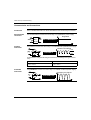
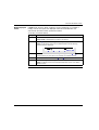
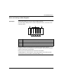
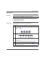
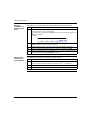
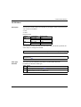
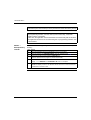
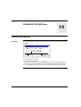
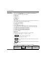
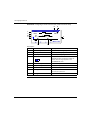
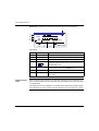
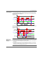
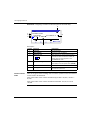
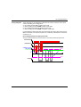
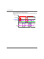
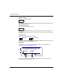
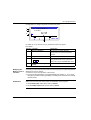
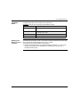
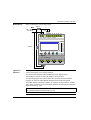
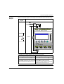
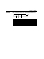
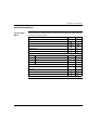
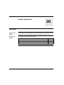
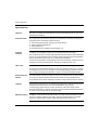
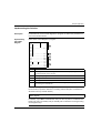
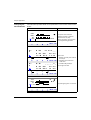
Below is the electrical diagram of the example and an illustration of the smart relay wiring:
Electrical
diagram
Connection to the smart relay
Mon
Fuse 1
100 ... 240 VAC
50 / 60 Hz
PB1
N
M N
I1 I2 I3 I4 I5 I6 I7 I8
100 ... 240 VDC
Inputs I1... I8 xx VDC
SRxxxxBD
Fuse 2
MENU / OK
Outputs
Q1 ... Q4: Relay 8A
1
Q1
2
1
Q2
2
1
Q3
2
1
Q4
2
L1
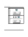
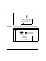
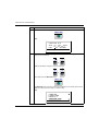
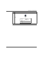
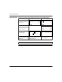
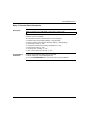
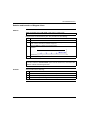
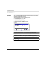
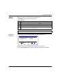
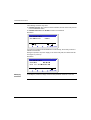
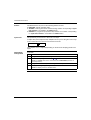
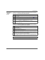
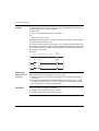
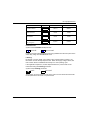
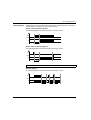
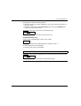
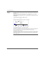
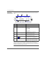
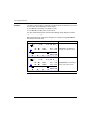
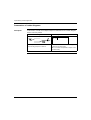
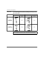
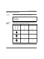
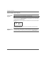
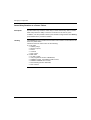
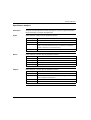
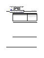
Depending on the ladder diagram, two solutions are possible:
Ladder diagram 1: Light off when idle
Ladder diagram 2: Light on when idle
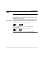
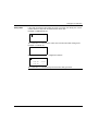
I1-------------[Q1
i1-------------[Q1
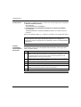
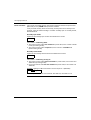
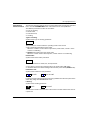
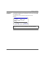
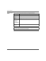
I1 corresponds to the true image of BP1,
i1 corresponds to the reverse image of BP1,
pressing BP1 activates input I1, so that the Q1 pressing BP1 activates input I1 and
therefore contact i1 is disabled, output Q1 is
output is activated and the lamp L1 turns on.
disabled and the lamp L1 turns off.
SR2MAN01EN 11/2005
157