1
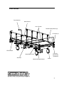
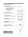
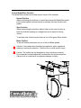
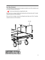
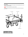
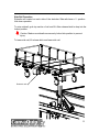
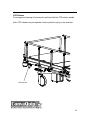
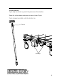
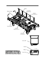
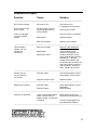
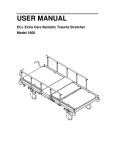
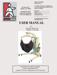
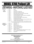
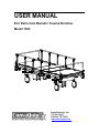
USER MANUAL
EC+ Extra Care Bariatric Trauma Stretcher
Model 1600
ConvaQuip Ind., Inc.
P.O. Box 3417
Abilene, TX 79604
www.convaquip.com
Table of Contents
Parts Locator
3
Safety Notes
5
Weight Limit
6
Power Requirements
6
Features
7
Function & Basic Operation
9
Electronic Components
16
Diagnostics & Repair
18
Inspection, Cleaning & Maintenance
19-20
Specifications
21
Warranty
22
1
2
Parts Locator
Push Handles
Head Section
Knee Section
Restraint Strap Mount (6)
IV Socket (4)
CPR Release
Push Bar
(Both Ends)
(Standard)
Brake/Steer Pedal
Side Rail
Handset Storage Bracket
Caster
3
4
Safety Notes
Warnings and Instructions
You must follow these warnings and instructions. Failure to observe
these safety precautions may result in personal injury or mechanical
failure. Read all instructions carefully before using the stretcher.
Always raise the siderails whenever the patient is lying on the stretcher.
Take special care to lock the casters securely when reclining or inclining
the stretcher and also when transferring patient to or from the stretcher.
Do not confuse the head and foot end of the stretcher when placing the
patient on the stretcher.
Make sure all persons and objects are clear of the stretcher when
articulating the stretcher. Do not place arms or head into frame while
operating.
Watch for pinch points. Keep clear of any mechanism motion.
Keep all objects out from under the stretcher. Certain parts under the
stretcher raise and lower when the stretcher is in motion. Make sure there
is nothing under the stretcher to interfere with proper stretcher operations.
Patient must be centered on the stretcher at all times. Do not sit on or exit
the stretcher at the head or foot end.
Do not move the stretcher using the siderails. Use the provided push
handles.
Do not service this device without first unplugging the power cord and
battery. Stretcher sections can move even with power cord unplugged
because of backup battery.
Make sure the handset cord is properly positioned before operating the
stretcher. Do not allow the cord to get caught in the moving parts of the
stretcher.
Do not operate this device if the power cord or any of the cords between
the associated parts are cut, frayed or loosely connected.
Do not use a stretcher with any missing or damaged parts.
5
Never disassemble your stretcher. If problems are found, contact
ConvaQuip customer service at 1-800-637-8436 or your local authorized
ConvaQuip dealer.
Weight limit: Never exceed the weight limit of your stretcher (1000 lbs.
combined weight of user and items on stretcher.) Exceeding weight limit
may cause stretcher to fail.
Power requirements: Electrical hazard may occur if device is plugged into
inadequate power supply. A power source of 120 V AC 60 hertz with a
capacity of at least 2.7 amperes must be available to operate the
stretcher.
Proper grounding is achieved only when stretcher is connected to a
“Hospital Grade Receptacle.”
Battery Backup: The systems battery automatically charges when the
power cord is plugged into an electric outlet. The battery maintains a
charge to allow the stretcher to be operated while stretcher is not plugged
into an electrical outlet.
Always plug in stretcher while not in use to maintain battery charge.
If the stretcher is operated for an extended period of time on battery
backup the battery will lose its charge, the actuators will not
function and the stretcher cannot be articulated.
6
Features
- 5-Function articulation
1) Raise and lower head section
2) Raise and lower foot section
3) Raise and lower stretcher top
4) Trendelenburg
5) Reverse Trendelenburg
- Power functions are powered by 24-volt DC electric actuators and lift columns.
- Electrical Power: 120 volt AC power transformer converts system to 24-volt DC.
Electrical actuators, lift columns, handset, controller and battery backup meet
CE, UL, ETL, & CSA listing.
- Power plug: Three-prong hospital type plug, grounding meets NFPA standards.
- Battery backup: Battery backup allows full use of stretcher when AC power
supply is not available for a limited time.
- Pendant control: Pendant control allows easy operation of all stretcher electrical
controls.
- Construction: Constructed entirely of steel, solid frame, powder coat painted.
- Stretcher top: 37” x 80” with provisions for restraint strap attachment.
- Siderails: 2-position fold down type.
- Casters: Heavy duty 8 inch casters with central locking and braking system.
- Push Bars: Removable push bars are located at the head and foot ends of the
stretcher.
- Push Handles: (2) self storing retractable push are located at the head
end of the stretcher.
- CPR release: To rapidly lower the head section pull and hold the CPR release
handle.
- Stretcher pad: 4” high density litter pad with low shear fabric.
- Accessory sockets: One IV socket on each corner of stretcher.
- IV Pole (optional): Removable telescopic IV pole with storage under stretcher
top.
7
- O2 holder (optional): Oxygen tank holder can be installed into one of the (4) IV
sockets.
8
Function & Basic Operation
5-Function Articulation
Pendant control allows easy operation of all stretcher electrical controls.
1) Raise and lower head section
2) Raise and lower foot section
3) Raise and lower stretcher top
4) Trendelenburg
5) Reverse Trendelenburg
Head Up and Head Down
buttons raise and lower the head section
Foot Up and Foot Down
buttons raise and lower the foot section
Bed Up and Bed Down
buttons raise and lower the stretcher
Trendelenburg Up
Button raises foot end and lowers head end
of stretcher
Reverse Trendelenburg Down
button raises head end and lowers foot end
of stretcher
9
Central Brake/Steer Function
The Brake/Steer pedals are located at each corner of the stretcher
Neutral Position
When positioning the stretcher in a small area place the Brake/Steer pedal
in the neutral position (shown below) to releasse the steer function and
brakes.
Steer Position
When transporting the stretcher without help use the steer function to
keep the stretcher tracking in a straight line and to assist in turning
corners.
To activate steer function press down on one of the green Steer pedals.
Brake Position
To set the brakes press down on one of the red Brake pedals.
Caution: Lock brakes when transferring a patient or when a patient is
entering or exiting the stretcher. Failure to do so could result in injury.
Caution: The brakes are not designed to stop a stretcher in motion.
Do not operate central brake/steer function when moving the stretcher.
Failure to do so could result in equipment damage or injury.
10
Push Bars (Standard)
The push bars are located at both the head end and foot end of the stretcher and
are used to facilitate the stretcher.
Do not move the stretcher using the side rails.
Each push bar is simply installed by inserting the push bars into each IV socket
located at each end of the stretcher.
Each push bar is simply removed by pulling the push bars out of the IV sockets
located at each end of the stretcher.
Push Bar
IV Socket
11
Push Handles
The push handles are located at the head end of of the stretcher and are used to
facilitate moving the stretcher.
Do not move the stretcher using the siderails.
To store the push handles, pull and hold the release knob while lowering the
push handle.
Push Handle
Head Section
Release Knob
12
Side Rail Operation
Siderails are located on each side of the stretcher. Side rails have a 2 - position
fold down operation.
To raise siderail, grab top section of rail and lift. Allow release latch to drop into the
locked position.
Caution: Make sure siderails are securely locked into position to prevent
injury.
To lower side rail, lift release latch and lower side rail.
Release Latch
13
CPR Release
For emergency lowering of head section pull and hold the CPR release handle.
Note: CPR release may not operate unless a patient is lying on the stretcher.
CPR Release
14
IV Pole (optional)
IV pole may be used at any one of the (4) corners of the stretcher.
Rotate the yellow release mechanism to raise or lower IV pole.
IV pole storage is provided under the stretcher top.
Release
IV Storage
15
Electronic Components
Linear Actuators control head section and foot section movement.
Lift Columns control vertical stretcher movement as well as
Trendelenburg/Reverse Trendelenburg movement.
Control Module controls all drive components.
Battery provides power when stretcher is not plugged into AC power.
Battery Charger charges battery when stretcher is plugged into AC power.
Handset (shown on page 9) is used to control all stretcher electronic functions.
16
Battery
Lift Column
Head End (3)
Battery Charger
Actuator
Knee Section (2)
Control Module
Actuator
Head Section (1)
Lift Column
Foot End (4)
Green LED
Control Module
Handset
Battery
1 2 3 4
Power Cord
17
Diagnostics & Repair
Problem
Cause
Solution
______________________________________________________________________
No Functions operate
No power to unit
Green Power-on light
does not glow
Electrical power cord not
properly plugged into the
control module
Power cord plugged
In but no functions
operate
Check power cord.
Is it plugged into receptacle?
Check cord for breaks.
Check for power to receptacle
Bad handset
Replace handset.
Bad control module
Replace control module.
_____________________________________________________________________________
Three actuators
operate “OK” one
actuator will
not operate
Bad control module
ISOLATE THE PROBLEM
Interchange connections on
Bad handset
control module so that
actuator is plugged into an
Bad actuator motor
actuator connection on the
control module that is working
satisfactorily. If problem
actuator now operates “OK”
but actuator that operating “OK”
now has a problem, either the
control module or handset is
faulty. Replace as required.
_____________________________________________________________________________
Actuator will not
function properly
or not at all
Defective wiring
Check wiring between control
and actuator. Reverse wires.
Defective actuator motor
Replace actuator
_____________________________________________________________________________
Battery will not charge
Defective wiring
Stretcher not grounded
Unit is not grounded between
power cord and frame or
between power cord and wall
receptacle
Check wiring between control
and battery.
Defective battery
Replace battery
_____________________________________________________________________________
Check ground (green wire)
between frame and power cord.
Is power cord plugged into a
grounded wall receptacle?
_____________________________________________________________________________
18
Inspection, Cleaning & Maintenance
Perform the following checks before using the stretcher:
- Do a careful walk around inspection of the stretcher. Look underneath the
stretcher to make sure there is nothing stored there. This area must be kept
clear to avoid any interference with stretcher parts, which move during operation.
- Lock the casters.
- Plug the power cord into a 120 volt grounded socket with a capacity of at least
2.7 amperes. Using the handset, cycle the stretcher through all of its operations.
Make sure that everyone including you is clear of the stretcher during these
operations. See that:
- All power stretcher operations work smoothly and stop in any desired
position.
- Stretcher height, angle of leg lift and backrest can be adjusted properly,
- Trendelenburg operates smoothly and can be stopped in any desired
position.
- Position the siderails, be sure they fold up and down properly.
- Test CPR release function. CPR release may not operate unless a patient is
lying on the stretcher.
- When you are satisfied that the stretcher is operating properly, instruct all
personnel who may be involved in the stretcher operation.
If problems are found, contact ConvaQuip customer service at 800-637-8436 or
your authorized ConvaQuip dealer.
Cleaning
Warning: Before cleaning any portion of the stretcher, disconnect power
cord from the wall outlet.
Caution: Before using any cleaning product, test it on the underside of the
stretcher. Never use any volatile or falmmable fluid (thinner, gasoline,
etc.) that could cause discoloration or deterioration.
Use mild soap and water or a nonabrasive hospital-grade detergent disinfectant
to clean the stretcher. Wet a cloth with the cleaning product and wring dry. Then
gently wipe off the stretcher. Use caution when cleaning around electrical
connections to prevent shock to the person or damage to the electricl
components.
19
Yearly Inspection and Maintenance
Once per Year:
1.
2.
3.
4.
5.
6.
7.
8.
Check all of the bolts to be sure that none worked loose.
Check that all pins are in their locked position and are securely fastened.
Check all welds.
Check all electrical connections for tightness.
Lubricate all pivot points with FDA approved grease or dry Teflon lubricant.
Check all electrical wires for any frays, kinks, or deterioration.
Check lock and steer castors for proper operation.
Check that CPR function operates properly.
Any discrepancies noted during inspection must be corrected before using the
stretcher.
20
Specifications
Product name: EC+ Extra Care Bariatric Trauma Stretcher
Model: 1600
Dimensions
Patient Weight capacity: 1000 pounds
Overall width: 40”
Overall length: 84”
Stretcher top: 37 x 80”
Stretcher top height: adjusts from 20-28”
Head section angle: 55°
Knee angle: 50°
Trendelenburg angle: 0-10°
Reverse trendelenburg angle: 0-10°
Siderail length: 62”
Siderail height above stretcher top: 12”
Caster size: 8”
Floor to base clearance: 9”
Floor to lift column clearance: 2”
Stretcher Weight: 450 lbs
Note: All dimensions are approximate
21
Warranty
Defective parts will be repaired or replaced by the company or its
appointed agent. The warranty does not cover damaged caused by misuse
or negligence, nor does it cover defects or damages by use of
unauthorized parts or services by an unauthorized person.
ConvaQuip, Ind., Inc. warrants the stretcher frame to be free from defects in materials
and workmanship for a period of (5) years from date of purchase. Wear items
including, but not limited to: casters, actuators, lift columns, control module,
handset, battery, battery charger, power cord, cables, release cables, bearings,
pins, release knob, and mattress are warranted to be free of defects in material
and workmanship for a period of one (1) year. If within such warranty period any
such products shall be proven to be defective, such products shall be repaired or
replaced, at the company’s option. This warranty does not include any labor or
shipping charges incurred in replacement part installation or repair of any such
product. The company’s sole obligation and your exclusive remedy under this
warranty shall be limited to such repair and/or replacement.
This warranty gives you specific legal rights, and you may also have other rights
that vary from state to state.
For warranty service please contact ConvaQuip Ind., Inc. Return authorization is
required. Do not return products without our prior consent.
Freight Damage: The carrier who delivers merchandise to your door is
responsible for loss and damages. Acceptance of the shipment by you is
acknowledgment that all articles delivered were in good condition and properly
packed. Therefore, all claims for loss or damage must be filed immediately with
the freight carrier. Then notify us. We will mark our records accordingly. After
settling claim, damaged merchandise will be picked up by the freight carrier and
returned. Should you need assistance with the claim, call customer service 800637-8436.
Return Goods: Call customer service at 800-637-8436
Do not return merchandise without prior authorization. All correspondence
relating to this warranty must indicate model and serial number and be
addressed to:
ConvaQuip Ind., Inc.
500 C.R. 239
Abilene, TX 79601
1600 User Manual 8/11 (Rev. C).doc
22