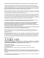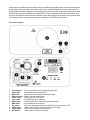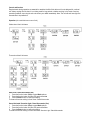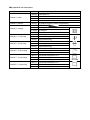
1
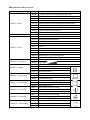
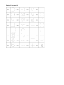
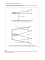
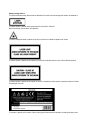
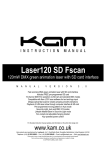
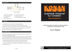
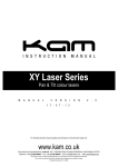
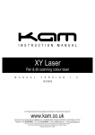
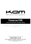
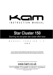
iLink laser series
Linkable colour DMX laser effects
M
A
N
U
A
L
0 9
V E R S I O
- 0 9 - 1 3
N
5
.
0
Kam iLink RGY | Kam iLink GBC | Kam iLink RBP | Kam iLink Blue 500
Due to continuous product development, please ensure that you have downloaded
the latest instruction manual for this product from the Kam website at www.kam.co.uk
For the latest updates and information on the entire Kam range visit:
www.kam.co.uk
Kam products are manufactured by: Lamba plc, Unit 1, Southfields Road, Dunstable, Bedfordshire, United Kingdom LU6 3EJ
Telephone: (+44) (0)1582 690600 • Fax: (+44) (0)1582 690400 • Email: [email protected] • Web: www.lambaplc.com
Due to continuous product development, specifications and appearance are subject to change. © Copyright Lamba plc 2013. E&OE.
M
A
D
E
I
N
C
H
I
N
A
Thank you for purchasing this Kam product, we are sure that it will serve you for many years to come.
To optimise the performance of this product, please read these operating instructions carefully to familiarise
yourself with the basic operations of this unit. Please retain them for future reference.This unit has been tested at
the factory before being shipped to you. To prevent or reduce the risk of electrical shock or fire, do not expose the
unit to rain or moisture. To prevent a fire hazard, do not expose the unit to any naked flame sources. Unplug this
apparatus during lightning storms or if it is unlikely to be used for long periods of time.
When installing the unit, please ensure you leave enough space around the unit for ventilation. Slots and openings
in the unit are provided for ventilation to ensure reliable operation of the product and to protect it from overheating.
To prevent fire hazard, the openings should never be blocked or covered.
If the unit is powered by the mains, always handle the power cable by the plug. Never pull out the plug by pulling
on the cable. Never touch the power cable when your hands are wet as this could cause an electric shock. Do not
tie a knot in the cable. The power cable should be placed such that it is not likely to be stepped on. A damaged
power cable can cause a fire or give you an electrical shock. Check the power cord periodicaly, if you ever find that
it is damaged, replace it before using the unit again. Contact your retailer for a replacement.
The voltage of the available power supply differs according to country or region. Be sure that the power supply
voltage of the area where this unit is to be used meets the required voltage written on the unit.
The lightning flash symbol inside a triangle is to alert the user to the presence high voltage within the
unit’s enclosure that may be of sufficient power to constitute a risk of electrical shock to persons.
Caution: to prevent the risk of electric shock, do not attempt to open the unit. No user-serviceable parts
inside. Refer all servicing to qualified service personnel.
The exclamation mark inside a triangle is intended to alert the user to the presence of important operating
and maintenance instructions in the literature accompanying the appliance.
Select the installation location of your unit carefully. Avoid placing it in direct sunlight or locations subject to
vibration and excessive dust. Do not use the unit where there are extremes in temperature (below 41ºF / 5ºC or
exceeding 95ºF / 35ºC).
Unpacking and safety Please unpack your new product carefully. Your new product should reach you in perfect
condition. Please check that no damage has occurred during transit. If any damage is found, do not operate your
unit. Please contact the retailer you purchased it from immediately. If there is any damage to the mains cable do
not use the device. Always disconnect the unit from the mains supply when carrying out any cleaning of the unit.
Manufacturer declarations
In compliance with the following requirements: RoHS Directive (2002/95/EU) and WEEE Directive (2002/96/EU),
and Battery Directive (2006/66/EU). If this product is ever no longer functional please take it to a recycling plant
for environmentally friendly disposal. Any supplied batteries can also be recycled.
CE declaration of conformity
Low Voltage Directive (2006/95/EU). The declarations are available on application from
[email protected]
Before putting the devices into operation, please observe the respective country-specific regulations.
Warning
This unit contains high power laser devices. Do not open the laser housing due to potential exposure to
unsafe levels of laser radiation. Please refer to the end of this manual for safe operation and installation of
this device.
The manufacturer will not accept liability for any resulting damages caused by the non-observance of this manual
or any unauthorized modification to the device.
Advance written notification should be made as early as possible to appropriate federal, state, and local authorities
providing show itinerary with dates and locations clearly and completely identified, and a basic description of the
proposed effects including a statement of the maximum power output intended. Such notifications should be made
to The Center for Devices and Radiological Health (CDRH), Office of Compliance (HFZ-342), 2098 Gaither Road,
Rockville, MD 20850 and the State and local radiation control offices/agencies for all shows to be performed within
their jurisdictions (a list of federal and state offices is available from the CDRH upon request).
Front and rear panels
0
1
2
3
4
5
6
7
8
9
10
12
Laser aperture
Power LED
Music LED
Remote receiver
Power switch
Fuse holder
Mains power
DMX In/Out
Key switch
Safety eyelet
Control panel
Microphone
This is the opening where laser light will appear from.
Indicates that the unit is switched on
Synchronises to any detected music/sound signal
Remote controller signal receiver
Use to power On or Off the unit
The replaceable fuse is held here
Power input With IEC socket and integrated fuse holder
3 pin male/female XLR connector
Insert the supplied safety key before being able to turn the laser On or Off
Used to attach a safety cable/chain when the unit is rigged
LED display and operation control buttons
Used to detect the music/sound signal
Control and function
Regular breaks during operation are essential to maximise the life of this device as it is not designed for continual
use. Always unplug the unit when it is not being used for long periods or before servicing. In the event of serious
operation problems, stop using the unit and contact your dealer immediately. Note: The unit will emit laser light five
seconds after it is powered on.
Operation (via control buttons on rear of unit)
Single colour Kam iLink lasers
Three colour Kam iLink lasers
Auto Show / Stand Alone mode (Aut)
1 Press the function button (Func) to enter Mode options
2 Press the function button until the LED panel shows Aut
3 Press the Enter button to confirm the setting
The laser will now be working in Auto Show / Stand Alone mode
Sound Activated / Sound-to-Light / Stand Alone mode (Sou)
1 Press the function button (Func) to enter Mode options
2 Press the function button until the LED panel shows Sou
3 Press the Enter button to confirm the setting
The laser will now be working in Sound Activated / Sound-to-Light / Stand Alone mode
Sound-to-Light / microphone sensitivity setting
1 Press the function button (Func) to enter Mode options
2 Press the function button until the LED panel shows S 6
3 Press the Up or Down buttons to adjust the microphone sensitivity
4 S 1 = low sensitivity / S 9 = high sensitivity / S 0 = mic is turned off
5 Press the Enter button to confirm the setting
DMX mode
1 Press the function button (Func) to enter Mode options
2 Press the function button until the LED panel shows 001
3 Press the Enter button to confirm the setting or change the address using the Up and Down buttons
4 Press the Enter button to confirm the setting
The laser will now be working in DMX mode
DMX mode / DMX address setting
1 Ensure the unit is in DMX mode (see above)
2 Press the Up or Down buttons to adjust the DMX address
3 Press the Enter button to confirm the setting
If multiple connected units are to be controlled in exactly the same way, set all units to the same starting address
(e.g. 001). If individual control of multiple connected units is required, each unit must have its own starting address.
This address must be at least 10 channels apart e.g. set the first unit to 001 and the second unit to 011, the third
unit to 021 and so on. The DMX controller will now control all the connected units separately.
Master/Slave mode
1 Press the function button (Func) to enter Mode options
2 Press the function button until the LED panel shows SLA
3 Press the Enter button to confirm the setting
The laser will now be working in Slave mode
To create a Master/Slave chain of units, one laser has to be designated as the Master unit whilst the remaining
units have to be set as Slave units. To set the Master unit, choose one laser and set it to your desired mode (Auto
mode, Sound-to-Light mode, etc). Next connect all other units via DMX cables. To achieve this, join the DMX
output of one unit to the next unit’s DMX input until all lasers are connected. Set all the Slave units to Slave mode
(see above). The Slave lasers will now duplicate the actions of the Master unit.
Operation (via IR remote control unit)
Remote Control mode
1 Press the function button (Func) on the rear of the laser to enter Mode options
2 Press the function button until the LED panel shows rEN
3 Press the Enter button to confirm the setting
The laser will now be working in Remote Control mode
To set the laser to Remote Control mode via the IR remote control unit, press the On/Off button (red button A) for
two seconds whilst the laser in any mode (except rEN or SLA modes).
A
B
On/Off button
Music mode
C
D/E
F
G
Auto mode
Colour buttons
Pause button
Pattern buttons
H
Pattern repeat
Press button to turn laser On or Off
Press button to activate Sound-to-Light mode
To set adjust the mic sensitivity, press Music and B buttons
Use the 0-9 digit buttons to increase or decrease sensitivity
Press button to activate Auto mode
Press buttons to cycle through laser’s available colours
Press button to pause the laser effect
Press the A and C buttons to change the laser patterns
Use the 0-9 digit buttons to choose any pattern from 1 to 48
Press button to cycle repeat the last and current patterns
Any control or setting in Remote Mode will be saved in RAM, until the unit is turned off.
DMX protocol for one colour lasers
Channel
Channel 1 - mode
Channel 2 - patterns
Channel 3 - zooming
Channel 4 – Y axis rolling
Channel 5 – X axis rolling
Channel 6 – Z axis rotating
Channel 7 – X axis rotating
Channel 8 – Y axis moving
Value
000-063
064-127
128-191
192-255
000-255
000-127
128-169
170-209
210-255
000-127
128-191
192-255
000-127
128-191
192-255
000-127
128-191
192-255
000-127
128-191
192-255
000-127
128-191
192-255
Function
Laser black out
Auto show
Sound activated show (music)
DMX mode (other channels activated)
32 patterns as shown in pattern list (see below)
100%-5% size
Zooming in
Zooming out
Zooming in and out
0-359 degree fixed Y axis rolled
Clockwise rolling
Anticlockwise rolling
0-359 degree fixed X axis rolled
Clockwise rolling
Anticlockwise rolling
0-359 degree fixed Z axis rotate
Clockwise rotating
Anticlockwise rotating
128 different fixed position on X
Clockwise moving
Anticlockwise moving
128 different fixed position on Y
Clockwise moving
Anticlockwise moving
DMX protocol for multi colour lasers
Channel
Channel 1 - mode
Channel 2 - patterns
Channel 3 - colour
Channel 4 – colour speed
Channel 5 - zooming
Channel 6 – X axis moving
Channel 7 – Y axis moving
Channel 8 – Y axis rolling
Channel 9 – X axis rolling
Channel 10 – Z axis rotating
Value
000-029
030-059
060-089
090-119
120-149
150-179
180-209
210-239
240-255
000-255
000-024
025-049
050-074
075-099
100-124
125-149
150-174
175-199
200-224
225-255
000-004
005-255
000-127
128-169
170-209
210-255
000-127
128-191
192-255
000-127
128-191
192-255
000-127
128-191
192-255
000-127
128-191
192-255
000-127
128-191
192-255
Function
Automatic show with original preprogrammed colour
Auto show with colour 1
Auto show with colour 2
Auto show with colour 3
Sound activated show with original preprogrammed colour
Sound activated show with colour 1
Sound activated show with colour 2
Sound activated show with colour 3
DMX mode
32 patterns as shown in pattern list (see below)
Blackout
Original preprogrammed colour
Colour 1
Colour 2
Colour 3
Alternate colour 1 and colour 2
Alternate colour 2 and colour 3
Alternate colour 1 and colour 3
Alternate colour 1, colour 2 and colour 3
Colour rolling
Stop
Slow > fast
100%-5% size
Zooming in
Zooming out
Zooming in and out
128 different fixed position on X
Clockwise moving
Anticlockwise moving
128 different fixed position on Y
Clockwise moving
Anticlockwise moving
0-359 degree fixed Y axis rolling
Clockwise rolling
Anticlockwise rolling
0-359 degree fixed X axis rolling
Clockwise rolling
Anticlockwise rolling
0-359 degree fixed Z axis rotating
Clockwise rotating
Anticlockwise rotating
Pattern list in channel 2
For safe operation of the iLink laser series
Please adhere to the distances shown in the diagram below. It is not reccommended that the laser is
pointed at an area where audience will be present.
Caution
Use of controls or adjustments or performance of procedures other than those specified herein may result in
hazardous radiation exposure.
Safety warning stickers
The yellow and black safety stickers that are attached to the laser unit are warnings that need to be adhered to.
The above sticker is placed next the laser aperture on the front of the unit.
Never look directly into the laser unit’s aperture.
The above triangular sticker is placed on the front of the unit to indicate the presence of a laser.
The above sticker is placed on the top/front of the unit and indicates that the unit is a Class 3B laser product.
The above sticker is placed on the top/rear of the unit to indicate that if the chassis is opened, exposure to Class
3B laser light can occur.
This sticker is placed on the bottom of the unit and gives further technical information including the laser power.
Specifications
Kam iLink Blue 500
Kam iLink RGY
Kam iLink RBP
Kam iLink GBC
Mains input/total power
Fuse
Sound control
Laser classification
Laser safety standard
Working temperature
DMX connections
DMX channels
Dimensions (WxHxD)
Nett weight
Red laser medium
Green laser medium
Blue laser medium
Beam diameter
Pulse data
Divergence (each beam)
Divergence (total light)
450mW blue
100mW red / 40mW green colour mixed to yellow
100mW red / 80mW blue colour mixed to pink
40mW green / 80mW blue colour mixed to cyan
AC100-240V, 50/60Hz / 12w
250V 1A slow blow (20mm glass)
Internal microphone
Class 3B
EN60825-1 : 2007
10~40˚C
3 pin XLR male and female
8 (single colour iLink lasers) / 10 (multi colour iLink lasers)
165 x 80 x 145mm / 6.5 x 3.15 x 5.7 inches (main unit not inc hanging bracket)
1.5Kg
LD GaAlAs 650nm, typical
DPSS Nd:YVO4, 532nm
LD GeAs 450nm, typical
<5mm at aperture
All pulses > 4Hz (<0.25sec)
<2 mrad
<90 degrees
Due to continuous product development, specifications and appearance are subject to change. © Copyright Lamba plc 2013. E&OE.