1
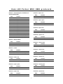
IN STR UC TI ON
M A NUA L
Kam LED Parbar MKII
Complete portable DMX LED lighting system
I n s t r u c t i o n
m a n u a l
v e r s i o n
1 . 0
Technical specifications
Power supply:
230V AC, 50 Hz~
Power consumption:
70W
Number of DMX channels:
15
DMX-512 connection:
3-pin XLR
Number of 10mm LEDs:
432
Beam angle:
25°
Sound-control:
via built-in microphone
Maximum ambient temperature Ta:
45°C
Maximum housing temperature TB (steady state):
60°C
Min.distance from flammable surfaces:
0.50m
Min.distance to lighted object:
0.10m
Fuse:
F 2A, 250V
Dimensions (LxWxH):
1110 x 55 x 295mm
Weight:
8Kg
Due to continuous product development, specifications and appearance are subject to change.
If this product is ever no longer functional please it take to a recycling plant for environmentally friendly disposal.
For the latest product updates and information on the entire Kam range visit:
www.kam.co.uk
Kam products are manufactured by: Lamba plc, Unit 1, Southfields Road, Dunstable, Bedfordshire, United Kingdom LU6 3EJ
Telephone: (+44) (0)1582 690600 • Fax: (+44) (0)1582 690400 • Email: [email protected] • Web: www.lambaplc.com
Kam LED Parbar MKII
Complete LED spotlight lighting system ideal for all forms of live performance
Thank you for choosing the Kam LED Parbar MKII lighting system, we are sure you will have many years of
use from this equipment but please read this user manual fully before attempting to use the kit.
This device has left our premises in absolutely perfect condition. In order to maintain this condition and to ensure a
safe operation, it is absolutely necessary for the user to follow the safety instructions and warning notes written in
this user manual. Important: damages caused by the disregard of this user manual are not subject to warranty.
Installation of the LED Parbar - Attach the LED Parbar to the top end of the stand and fasten the fixation screw
making sure the unit’s weight is evenly balanced. Please note: for overhead rigging in public or industrial areas, a
series of safety instructions have to be followed that this manual can only give in part.
DMX-512 connection - Only use a stereo shielded cable and 3-pin XLR-plugs and connectors in order to connect
the controller with the fixture or one fixture with another.
Master/Slave operation - This enables several devices can be synchronized and controlled by one Master
device.On the rear panel you can find an XLR jack and an XLR plug, which can be used for connecting several
devices. Choose the device which is to control the effects. Connect the OUT jack with the IN plug of the next
device. Set the Master device to SOUND mode and set each Slave device to the same DMX address.
Mains connection - The device must only be connected with an electric installation carried out in compliance with
the IEC standards. The electric installation must be equipped with a Residual Current Device (RCD) with a
maximum fault current of 30mA. Lighting effects must not be connected to dimming-packs.
Cleaning and maintenance - Look out for and maintain the following: 1) All screws used for installing the devices
or parts of the device have to be tightly connected and must not be corroded. 2) There must not be any
deformations on the housings, fixations and installation spots (ceiling, suspension, trussing). 3) The electric power
supply cables must not show any damages, material fatigue (e.g. porous cables) or sediments. Further instructions
depending on the installation spot and usage have to be adhered by a skilled installer and any safety problems
have to be removed. Disconnect from mains before starting maintenance operation! We recommend frequent
cleaning of the device. Please use a soft lint-free and moistened cloth. Never use alcohol or solvents! There are no
serviceable parts inside the device except for the fuse. Maintenance and service operations are only to be carried
out by authorized dealers.
Replacing the fuse - If the fine-wire fuse of the device fuses, only replace it by a fuse of same type and rating.
Before replacing the fuse, unplug mains lead. Step 1: Open the fuseholder on the rear panel with a screwdriver.
Step 2: Remove the old fuse from the holder. Step 3: Install the new fuse in the fuseholder. Step 4: Replace the
fuseholder in the housing. Should you need any spare parts, please use genuine parts. If the power supply cable of
this device becomes damaged, it has to be replaced by a special power supply cable available at your dealer.
Should you have further questions, please contact your dealer.
Operation - After you have connected the unit to the mains, the LED Parbar starts running and the display lights
up. The device has two operating modes. It can be operated in sound controlled or in DMX-controlled mode.
You can choose the desired mode via the buttons MENU, UP and DOWN:
When display shows A*** you can choose the desired DMX address via the UP or DOWN buttons.
When display shows *512 the unit is in DMX mode. To switch to sound control mode, press the UP button.
When display shows *SND the unit is in sound control mode. To switch to DMX mode, press the DOWN button.
When display shows S*** you can choose the desired speed of the internal programs. Default is 51; for
increasing speed press the DOWN button, for decreasing speed press the UP button.
DMX controlled operation - You can control the spots individually via your DMX controller.
2
Kam LED Parbar MKII DMX protocols
Channel 7 – Spot 2: red
Channel 1 – Internal Programs, Auto Mode and
Sound Controlled Mode
Value
000 – 009
010 – 029
030 – 049
050 – 069
070 – 089
090 – 109
110 – 129
130 – 149
150 – 169
170 – 189
190 – 209
210 – 229
230 – 249
250 – 255
Value
000 – 255
Function
Off
Program 1
Program 2
Program 3
Program 4
Program 5
Program 6
Program 7
Program 8
Program 9
Program 10
Program 11
Auto Mode: Internal Programs
Sound Controlled Mode
Function
Dimming from 0 – 100%
Channel 8 – Spot 2: green
Value
000 – 255
Function
Dimming from 0 – 100%
Channel 9 – Spot 2: blue
Value
000 – 255
Function
Dimming from 0 – 100%
Channel 10 – Spot 3: red
Value
000 – 255
Function
Dimming from 0 – 100%
Channel 2 – Master Dimmer
Value
000 – 009
010 - 255
Function
Off
Dimming from 0 – 100%
Channel 11 – Spot 3: green
Value
000 – 255
Function
Dimming from 0 – 100%
Channel 3 – Strobe
Channel 12 – Spot 3: blue
Value
000 – 009
010 - 255
Function
Off
Flash, with increasing speed
Value
000 – 255
Channel 13 – Spot 4: red
Channel 4 – Spot 1: red
Value
000 – 255
Value
000 – 255
Function
Dimming from 0 – 100%
Value
000 – 255
Function
Dimming from 0 – 100%
Function
Dimming from 0 – 100%
Channel 15 – Spot 4: blue
Channel 6 – Spot 1: blue
Value
000 – 255
Function
Dimming from 0 – 100%
Channel 14 – Spot 4: green
Channel 5 – Spot 1: green
Value
000 – 255
Function
Dimming from 0 – 100%
Value
000 – 255
Function
Dimming from 0 – 100%
3
Function
Dimming from 0 – 100%
© COPYRIGHT LAMBA plc 2009. E&O E.
Operation via the foot switch - Connect the foot switch with the LED Parbar device via the 5-pin conection cable
with plug. The foot switch can be operated in sound controlled (*SND) or in DMX-controlled (*512) mode.
Pedal functions are as follows:
Pedal 4
Blackout
Pedal 3
Hold
Sound On
Pedal 2
Pedal 1
Presets: 1 x press = White / 2 x press = Red / 3 x press = Green / 4 x press = Blue
5 x press = Cyan / 6 x press = Yellow / 7 x press = Violet
8 x press = Color change every second in a continuous loop as described above
9 x press = Color fade every 3 seconds in a continuous loop as described above
To discontinue operation of the foot switch, press pedals 1 and 4 down simultaneously, then release both
pedals simultaneously.
When linking two or more LED Parbars together using one foot controller
Setting up the first unit
1. Power up first unit (this will be known as the Master unit).
2. Press the left hand menu button until either AUTO or SND is displayed
3. When either AUTO or SND is displayed then choose which mode you require by pressing the centre button.
AUTO = Automatic mode, SND = Sound-to-Light mode. The master unit is now set up and ready to use.
Setting the second unit
1. Power up the second unit (this will be known as the Slave unit). Usually either AUTO or SND will be displayed.
2. Now press the left hand menu button until the display shows an (A) followed by a number. Using the right hand
down button, press until the display shows A1.
3. Now press the menu button once again, the display will show either AUTO or SND depending on the setting.
4. Press the right button and 512 will be displayed. At this point you must wait approx 20 seconds and the display
will automatically change to D1. The slave unit is now set.
5. Repeat the above section of the instructions on all other slave units that you require to be linked.
6. All Slave units must be set to D1. There can only be one Master unit.
7. Link the LED Parbars together using a 3 pin XLR to XLR DMX cable.
8. Connect the DMX Output socket on the Master unit to the DMX Input on the Slave unit. If you are connecting
more LED Parbars, connect the DMX Output of the each Slave unit to the DMX Input socket of the next unit.
Using the LED Parbar with a DMX controller
Each LED Parbar uses fifteen DMX channels. To connect a single unit to a DMX controller you will need to decide
what address you want the DMX to start at. Usually we suggest you set the address at channel 1 to begin with.
The address settings on the LED Parbar are determined in the A section of the menu.
1. Power up the LED Parbar and press the left hand menu button until ‘A’ followed by a digit is displayed e.g. A8.
2. Using the up and down buttons you can change the display number, press the Down until A1 is displayed.
3. Now press the left hand menu button once more then press the right hand button once, this will now display
512. Wait approximately 20 seconds and the display will automatically change to D1 this is now set to DMX
Address Channel 1, if a different starting address is required press the left hand menu button until A is
displayed and using the up and down buttons, you can set the desired DMX start address. Follow step 3. in this
section to complete the set up. Whatever number is selected in the A menu will be the DMX512 channel.
Setting all linked LED Parbars to react in the same way via a DMX controller
Set all LED Parbars to D1. Follow the instructions above in the ‘Setting the second unit’ section.
Setting all linked LED Parbars to react independently via a DMX controller
This will mean addressing the LED Parbars with different addresses. Make sure your DMX controller has enough
channels available to do this. Set the first LED Parbar unit to D1. The second units needs to be 15 channels higher
than this number, so in this case the start address will be 16. Press the menu button to access the A menu as
described above. Next use the up and down buttons until A16 is displayed. Press the menu button once more then
press the right hand down button. 512 will be displayed, wait approximately 20 seconds and the display will
automatically change to D16, this is now set to DMX address channel 16. Continue using this formula adding 15
each time for connecting more LED Parbars. Always make sure your controller has enough free channels.
Never overlap the DMX channels.
4