1
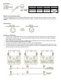
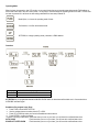
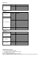
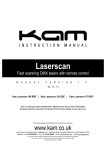
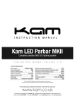
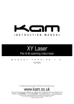
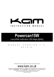
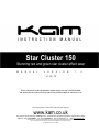
Star Cluster 150 Stunning red and green star cluster effect laser M A N U A L V E R S I O N 1 . 0 14 - 05 - 12 Due to continuous product development, please ensure that you have downloaded the latest instruction manual for this product from the Kam website at www.kam.co.uk For the latest updates and information on the entire Kam range visit: www.kam.co.uk Kam products are manufactured by: Lamba plc, Unit 1, Southfields Road, Dunstable, Bedfordshire, United Kingdom LU6 3EJ Telephone: (+44) (0)1582 690600 • Fax: (+44) (0)1582 690400 • Email: [email protected] • Web: www.lambaplc.com If this product is ever no longer functional please take it to a recycling plant for environmentally friendly disposal. Due to continuous product development, specifications and appearance are subject to change. © Copyright Lamba plc 2011. E&OE. Thank you for purchasing this KAM product, we are sure that it will serve you for many years to come. To optimise the performance of this product, please read these operating instructions carefully to familiarise yourself with the basic operations of this unit. After you have read the instructions, please retain them for future reference. This unit has been tested at the factory before being shipped to you. To prevent or reduce the risk of electrical shock or fire, do not expose the unit to rain or moisture. To prevent a fire hazard, do not expose the unit to any naked flame sources. Unplug this apparatus during lightning storms or if it is unlikely to be used for long periods of time. When installing the unit, please ensure you leave enough space around the unit for ventilation. Slots and openings in the unit are provided for ventilation to ensure reliable operation of the product and to protect it from overheating. To prevent fire hazard, the openings should never be blocked or covered. Always handle the power cable by the plug. Never pull out the plug by pulling on the cable. Never touch the power cable when your hands are wet as this could cause an electric shock. Do not tie a knot in the cable. The power cable should be placed such that it is not likely to be stepped on. A damaged power cable can cause a fire or give you an electrical shock. Check the power cord periodicaly, if you ever find that it is damaged, replace it before using the unit again. Contact your retailer for a replacement. The voltage of the available power supply differs according to country or region. Be sure that the power supply voltage of the area where this unit is to be used meets the required written on the unit. The lightning flash symbol inside a triangle is intended to alert the user to the presence high voltage within the unit’s enclosure that may be of sufficient power to constitute a risk of electrical shock to persons. Caution: to prevent the risk of electric shock, do not attempt to open the unit. No user-serviceable parts inside. Refer all servicing to qualified service personnel. The exclamation mark inside a triangle is intended to alert the user to the presence of important operating and maintenance instructions in the literature accompanying the appliance. Any modification carried out on the unit may invalidate the unit’s warranty. If applicable, only use the stand, tripod or bracket specified or sold with the apparatus. Select the installation location of your unit carefully. Avoid placing it in direct sunlight or locations subject to vibration and excessive dust. Do not use the unit where there are extremes in temperature (below 41ºF / 5ºC or exceeding 95ºF / 35ºC). Unpacking and safety: Please unpack your new product carefully, your new product should reach you in perfect condition. Please check that no damage has occurred during transit. If any damage is found, do not operate your unit. Please contact the retailer you purchased it from immediately. If there is any damage to the mains cable do not use the device. Always disconnect the unit from the mains supply when carrying out any servicing or cleaning of the unit. The serial number for this equipment should be located on the rear or underside of the unit. Please make a note of this number as you will need it for your warranty, it is a good idea to keep a copy of the serial number for your own records. Unpacking Instructions CAUTION! Immediately upon receiving a fixture, carefully unpack the carton, check the contents to ensure that all parts are present and have been received in good condition. Notify the shipper immediately and retain packing material for inspection if any parts appear damage from shipping or the package itself shows signs of mishandling. Save the package and all packing materials. In the event that a fixture must be returned to the retailer, it is important that the fixture be returned in the original box and packing. Contents 1 x laser, 2 x keys (for key switch), 1 x interlock connector, 1 x remote control, 1 x power cord, 1 x user manual, 1 x laser safety guide Power Supply Cable (EU) Brown Light Blue Cable (US) Black White Pin Live Neutral Yellow/Green Green Earth International L N DMX-512 connection between fixtures The fixture is equipped with 3-pin XLR sockets for DMX input and output. Thesockets are wired in parallel. Only use a shielded twisted-pair cable designed for3-pin XLR-plugs and connectors in order to connect the controller with the fixtureor one fixture with another. XLR-connection Building a serial DMX-chain If you are using a standard DMX-controller, you can connect the DMX-output of the controller directly with the DMX-input of the first fixture in the DMX-chain. If you wish to connect DMX-controllers with other XLR-outputs, you need to use adapter cables. (DMX controller not supplied). Connect the DMX-output of the first fixture in the DMX-chain with the DMX-input of the next fixture. Always connect output with the input of the nextfixture until all fixtures are connected. If you use a controller with 5 pins DMX connector, you need to use a 5 to 3pins adapter. The DMX output and input connectors are pass-through to maintain the DMXcircuit, when power is disconnected to the unit. Each fixture needs to have a DMX address to receive the data from the controller. The DMX address number which could be read from rear panel of each fixture is between 000~511. Proper laser set up &usage This fixture has been designed to be hung. It is recommended for safety purposes,your lighting effect are properly mounted using a suitable hanging clamp andsafety cable. Items appropriate for safe and effective mounting are easilysourced from your lighting vendor. International laser safety regulations require that lasers must be operated in thefashion illustrated below, with a minimum of 3 metres (9.8 ft) of vertical separation between the floor and the lowest laser light vertically. Additionally, 2.5 metres of horizontal separation is required between laser light and audience or other public spaces. Front Panel 1. Laser output – Laser output aperture 2. Power – Main power indicated LED. Red is ON 3. Music/IR – Synchronize to detected music signal / IR indicator (flashing for each signal received) 4. IR – Infrared remote receiver Rear Panel 5. Switch – Switch on and off the power 6. Mains input – with socket and intergrated fuse holder 7. DMX input - 3 PIN Male XLR 8. DMX output – 3 PIN Female XLR 9. Interlock – For emergency laser stop 10. Key switch 11. Safety eye – Attach the safety cable 12. Microphone – to detect music/sound 13. LED function display Operating Mode When the laser is powered on, the LCD monitor on rear panel shows the current operating standalone mode, DMX address or Slave mode. With help of the LCD control panel, it is very easy to set and change the operating mode of the laser. The next time the laser is powered on it will show the last setting used before the laser was powered off. Mode Option, to choose the operating mode of laser. Confirmation, to confirm the selected mode. UP/DOWN, to change operating mode, parameter or DMX address. Operation Display Aut Sou Stand alone mode pre-programmed effect Automatic show with slow effect Sound activated show ATTENTION! In pre-programmed standalone MUSIC SHOW mode, the laser beam will be blank-out in 3 seconds without AUDIO/MIC activated signal. Standalone Pre-program Laser Show Press FUNC to enter MODE OPTION. Use the up/down buttons to select either AUT or SOU. Press UP or DOWN to select your favourite Standalone mode as above. Press ENTER to confirm the setting. The laser is working in stand alone. Each time when you turn on your laser, you will have this confirmed laser show. AUTO SHOW Each time when you turn on your laser, you will have this confirmed laser show. SOUND ACTIVATED SHOW Each time when you turn on your laser, you will have this confirmed laser show. MASTER/SLAVE MODE Press FUNC to enter the MODE selection Use the up/down buttons to select SLA for Slave mode Press ENTER to confirm the setting Now the laser is working in SLAVE MODE. Connect the MASTER laser with several SLAVE lasers using a DMX cable. The SLAVE lasers will produce exactly the same laser show as MASTER laser. SOUND ACTIVATED MODE – SENSITIVITY SETTING Press FUNC till to you see S 6 Use the UP/DOWN buttons to set microphone sensitivity. S0 is no sound, from S1 to S9, the sensitivity level increases. Press ENTER to confirm and save the setting. DMX MODE Press FUNC to enter the MODE selection The LED panel will show 001 for DMX mode Press ENTER to confirm the setting Now the laser is working in DMX mode. Use the up/down buttons to select the DMX address. Note: In DMX MODE, once the DMX cable is connected to the laser and DMX controller, the DMX LED in front panel of laser will be ON. DMX Protocol Channel Ch 1 DMX Mode 1 Channel Ch 2 – Rotation Ch 3 – Swing Ch 4 – Colour selection Ch 5 - Strobe DMX Mode 2 Channel Ch 2 – Rotation Ch 3 – Swing Ch 4 – Red laser Ch 5 – Green laser DMX Value 000-050 051-100 101-150 151-200 201-255 Description Laser Black Out Auto show Sound activated show DMX mode 1 DMX mode 2 DMX Value 000-004 005-127 128-133 134-255 000-255 000-004 005-020 021-035 036-050 051-080 081-110 111-140 141-170 171-200 201-255 000-004 005-254 255-255 Description No function Clockwise rotation (slow – fast) Stop Counter clockwise rotation (slow – fast) Swing range (short – long) Blackout Red on Green on Red & Green on Red strobe Green strobe Red & Green strobe Red on & Green strobe Green on & Red strobe Red & Green (alternate strobe) No function Strobe (slow – fast) Strobe to sound DMX Value 000-004 005-127 128-133 134-255 000-255 000-004 005-010 011-254 255-255 000-004 005-010 010-254 255-255 Description No function Clockwise rotation (slow – fast) Stop Counter clockwise rotation (slow – fast) Swing range (short – long) Blackout Red Strobe (slow – fast) Strobe to sound Blackout Green Strobe (slow – fast) Strobe to sound REM MODE (Remote Optional) Press FUNC to enter the MODE selection Use the up/down buttons to select REM for Remote mode Press ENTER to confirm the setting Please check Remote Instruction for remote control details. Note: In any standalone mode (except REM and SLA), press ON/OFF for 2 seconds to activate the remote function. Remote Instruction Button Function Description ON/OFF In REM mode, to turn ON/OFF laser. In any stand alone mode, except for SLA mode, pressing this button for 2 seconds will activate the REM mode. Auto Auto running Music Sound Activated show. The blue music LED indicator is flashing when sound signal is detected. Effect pause Colour changing Cycle through the colours. Red > Green > R&G > Original Colour flashing A for Red flashing and B for Green flashing Firework effect Works with numbers Motor speed setting Works with numbers Number buttons Specifications Mains Input: Fuse: Total Power: Music Control: Laser Power (per unit): Laser Classification: Laser Safety Standard: Condition Temperature: DMX Connections: DMX Channels: Dimensions: Nett weight: Pause the effect AC100~240V, 50/60Hz 250V /1A Slow Blow (20mm Glass) 20w Audio / Sound Activated 100mW 650nm Red CW 50mW 532nm Green CW Class 3B EN60825-1 2007 10~40°C 3 pins XLR Male/Female Max 5 channels 160 x 180 x 260mm 1.8Kg Level of colour flashing, motor speed & firework effect. 0 – less 9 – more