1
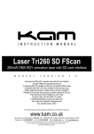
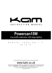
Kam K-UV 18X1W Strip Classic blacklight effect UV light bar M A N U A L V E R S I O N 1 . 0 2 1 - 0 8 - 1 4 Due to continuous product development, please ensure that you have downloaded the latest instruction manual for this product from the Kam website at www.kam.co.uk For the latest instruction manual updates and information on the entire Kam range visit: www.kam.co.uk Kam products are manufactured by: Lamba plc, Unit 1, Southfields Road, Dunstable, Bedfordshire, United Kingdom LU6 3EJ Telephone: (+44) (0)1582 690600 • Fax: (+44) (0)1582 690400 • Email: [email protected] • Web: www.lambaplc.com Made in China. Due to continuous product development, specifications and appearance are subject to change. © Copyright Lamba plc. E&OE. Thank you for purchasing this Kam product, we are sure that it will serve you for many years to come. To optimise its performance, please read these operating instructions carefully to familiarise yourself with the basic operations of this unit. Please retain them for future reference. This unit has been tested at the factory before being shipped to you. To prevent or reduce the risk of electrical shock or fire, do not expose the unit to rain or moisture. To prevent a fire hazard, do not expose the unit to any naked flame sources. Unplug this apparatus during lightning storms or if it is unlikely to be used for long periods of time. When installing the unit, please ensure you leave enough space around the unit for ventilation. Slots and openings in the unit are provided for ventilation to ensure reliable operation of the product and to protect it from overheating. To prevent fire hazard, the openings should never be blocked or covered. The unit is powered by mains electricity, always handle the power cable by the plug. Never pull out the plug by pulling on the cable. Never touch the power cable when your hands are wet as this could cause an electric shock. Do not tie a knot in the cable. The power cable should be placed such that it is not likely to be stepped on. A damaged power cable can cause a fire or give you an electrical shock. Check the power cord periodicaly, if you ever find that it is damaged, replace it before using the unit again. Contact your retailer for a replacement. The voltage of the available power supply differs according to country or region. Be sure that the power supply voltage of the area where this unit is to be used meets the required written on the unit. The lightning flash symbol inside a triangle is to alert the user to the presence high voltage within the unit’s enclosure that may be of sufficient power to constitute a risk of electrical shock to persons. Caution: to prevent the risk of electric shock, do not attempt to open the unit. No user-serviceable parts inside. Refer all servicing to qualified service personnel. The exclamation mark inside a triangle is intended to alert the user to the presence of important operating and maintenance instructions in the literature accompanying the appliance. Select the installation location of your unit carefully. Avoid placing it in direct sunlight or locations subject to vibration and excessive dust. Do not use the unit where there are extremes in temperature (below 41ºF / 5ºC or exceeding 95ºF / 35ºC). Unpacking and safety Please unpack your new product carefully. Your new product should reach you in perfect condition. Please check that no damage has occurred during transit. If any damage is found, do not operate your unit. Please contact the retailer you purchased it from immediately. If there is any damage to the mains cable do not use the device. Always disconnect the unit from the mains supply when carrying out any cleaning of the unit. Manufacturer declarations In compliance with the following requirements: RoHS Directive (2002/95/EU) and WEEE Directive (2002/96/EU). If this product is ever no longer functional please take it to a recycling plant for environmentally friendly disposal. CE declaration of conformity R&TTE Directive (1999/5/EU), EMC Directive (2004/108/EU), Low Voltage Directive (2006/95/EU). The declarations are available on application from [email protected] Before putting the devices into operation, please observe the respective country-specific regulations. What is included in the package 1 x Kam K-UV 18X1W Strip unit / 1 x IEC power cable / 1 x instruction manual Overhead rigging Important - the installation must be carried out by qualified service personal only. Improper installation can result in serious injuries and /or damage to property. Overhead rigging required extensive experience. Working load limits should be respected, certified installation materials should be used, the installed unit should be inspected regularly for safety. l Make sure the area below the installation place is free from unwanted persons during rigging, de-rigging and servicing. l Locate the fixture in a well ventilated spot, far away from any flammable materials and/or liquids. The fixture must be fixed at least 50cm from surrounding walls l The device should be installed out of reach of people and outside of areas where persons may walk by or be seated. l Before rigging make sure that the installation area can hold minimum point load of 10 times the device`s weight. l The device should be well fixed; a free swinging mounting is dangerous. l Do not cover any ventilation opening as this may result in overheating l Before first time use, the unit should be inspected for safety. Inspection the unit regularly every year. Key to rear panel diagram 1. Power switch - after connection to mains power, use this to turn the unit ON 2. Mains power input IEC socket and integrated fuse holder. Connect the supplied IEC cable to the input and the mains 3. Mains power output/link IEC socket. Connect an IEC link cable to this output and to the next unit in a chain of units 4. LED display - shows the various menus and the selected functions 5. Menu buttons - used to select the different menu items 6. DMX input and output - 3 pin XLR interface for DMX connections Operating instructions The unit has the following working modes: l Auto mode - built-in programs l Sound-to-Light mode - sound activated operation via the built-in microphone l DMX512 mode - control via a DMX controller l Master/Slave mode – multiple units in a connected chain are controlled by the first ‘Master’ unit Main menu To select any of the menu options, press the MENU button to select the mode required. Once you have made a selection then press ENTER to confirm. Use the UP and DOWN buttons to choose the desired menu option. Auto mode operation Press the MENU button, the following functions can be selected and then confirmed using the ENTER button: AUTO the unit runs the preset built-in shows; CF increases brightness then decreases brightness in a fading/pulsing effect. The speed can be adjusted using the UP and DOWN buttons (from 00 slowest to 99 fastest). CC preset program - the speed of change can be adjusted using the UP and DOWN buttons (from 00 very slow to 99 fastest – for best results use numbers 88-99). CS choose which LEDs are on or off. Use the UP & DOWN buttons to make your selection. Y000 press the MENU button for five seconds until Y000 shows in the LED display. The UV brightness can be adjusted using the UP and DOWN buttons. Sound-to-Light mode operation Press the MENU button until you see the letters SoUd. Confirm your choice using the ENTER button. The unit will now respond to the beat of any loud music playing. The built-in microphone reacts best to the bass sounds in a tune. DMX512 mode operation DMX addressing - using the controls on the rear of the unit you can assign the DMX address for the unit. This is defined as the first channel from which the unit will respond to a connected DMX controller. If you set, for example, the address to channel 7, the unit will use channels 7 to 14 for control. Please, be sure that you don’t have any overlapping channels in order to control each unit correctly and independently from any other units in a DMX chain. If two, three or more units are addressed similarly, they will work similarly. In DMX mode you can choose the address from 1 to 512. When connected via DMX and powered up, the unit will at first reset itself then d001 will flash in the LED control display on the rear of the unit. You can now set the desired DMX address using the UP and DOWN buttons. For a list of DMX channel controls, please see the table below. Building a serial DMX chain Connect the DMX OUT of the first unit to the DMX IN of the next unit. Always connect one output with the input of the next unit until all units are connected. Caution: the last unit in the DMX chain has to have its DMX cable terminated with a terminator. Solder a 120 resistor between Signal (–) and Signal (+) into a 3-pin XLR-plug and plug it in the DMX OUT of the last unit. DMX channel control Channel Function Value Description CH1 Brightness 000-255 UV brightness 0-100% CH2 Strobe 000-255 Adjusts the strobe speed from slow to fast CH3 No function 000-029 No function CH3 Bank brightness 030-255 Adjusts the brightness of each bank (for static use) CH4 No function 000-084 No function CH4 Fade/pulse effect 085-169 The speed can be adjusted by CH5* CH4 Chase effect 170-255 The speed can be adjusted by CH5* CH5 Speed adjustment for CH4 000-255 Speed adjust when CH4 is set to 085-169 or 170-255 * For best use of channel 5 speed control, use address 240-255. Master/Slave mode operation Setting the Master unit Press the MENU button to select the desired mode, Auto or Sound-to-Light. Press enter to confirm. Setting the Slave units Ensure that no DMX controller is connected then connect other units to each other in a chain using DMX cables (from DMX OUT on the Master unit to DMX IN on the first Slave, then DMX OUT on the first Slave to DMX IN on the second Slave (and so on). Ensure that all Slave units are set to Sub. on the rear display. All connected Slave units will follow the controls from the Master unit. Troubleshooting Problem Check list Troubleshooting No output the unit does not appear to work 1. Check if the power cord is connected to the input mains socket of the unit. 2. Check if the ambient temperature in a safe range. 1. Make sure there is mains present to the cable, check the fuse or replace the cable. 2. Ensure the ambient temperature is suitable. LEDs are dimmed 1. Check if the power cord is connected to the input mains socket of the unit. 1. Make sure the mains input voltage is the correct voltage. No DMX input 1. Check that the cable is not damaged. 2. Check the polarity of the pin connections is correct. 3. Check lf the unit is in DMX mode. 4. Check if 2 units are set as Master units in a chain. 1. Change the DMX cable. 2. Correct the DMX polarity or change the cable. 3. Set up the function mode as DMX. 4. Set all other units as Slave units in the chain. Technical specifications DMX512 control channels: 5 DMX512 input & output connection: 3 pin XLR Mode: DMX512 / Auto / Sound-to-Light / Master/Slave Power consumption: 30w LEDs: 18 x 1w ultraviolet Power supply: IEC mains / AC 100-240V 50/60Hz Fuse: 250V 1.0A Dimensions (WxDxH): 920 x 80 x 90mm (not including brackets) Weight: 3.2Kg Due to continuous product development, specifications and appearance are subject to change. © Copyright Lamba plc. E&OE.