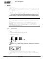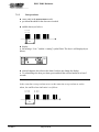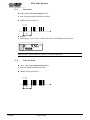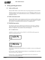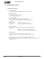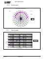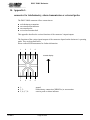
1
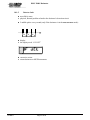
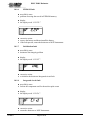
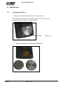
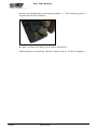
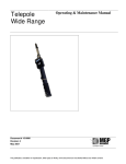
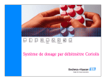
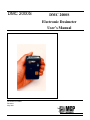
DMC 2000S
DMC 2000S
Electronic Dosimeter
User’s Manual
Document # 15-00007
Revision 1
May 2001
DMC 2000S Dosimeter
REVISION LOG: DMC 2000S Electronic Dosimeter User’s Manual
Date
Revised
Pages
Comments
0
10/21/98
N/A
Original MGPI document # 15-00007,
based upon MGPSA document #
115170AA
1
05/01/01
Revision #
Revised for new firmware version of
DMC 2000
Page 20
Moved ‘SAT’ to the end of section
(5.3.2)
Page 23
Moved ‘Dosimeter Serial’ number to the
beginning of section (5.3.2)
Page 35
Added ‘Watch/Clock’ function to section
(6.4.2)
Page 35
Added description and function of ‘EXT’
mode (exercise training) to section
(6.4.2)
Page 54
Added ‘Calibration Mode’ in section
(10.1.4)
All
Added ‘Warning’ to pre-alarms
All
Changed all units in graphics and units to
reflect ‘mRem’ and mRem/h
Page 63
15-00007
Page 2 of 65
Updated part numbers
DMC 2000S Dosimeter
TABLE OF CONTENTS
1.
General
6
1.1
1.2
1.3
1.4
1.5
Document overview
Contents 6
Direct access to information
Conventions
Illustrations
6
8
8
8
2.
Operating modes of the DMC 2000S dosimeter
9
2.1
Operating Mode
9
2.1.1.
2.1.2.
9
9
2.2
Autonomous mode
Satellite mode
Dosimeter function mode
2.2.1.
2.2.2.
2.2.3.
2.2.4.
9
Dosimeter storage mode
Pause mode
Measurement mode
Compatibility
9
10
10
10
3.
Description
11
3.1
3.2
3.3
Front view
Back view 11
Display 12
11
The dosimeter’s top-mounted display allows viewing of measurements and alarms.
12
4.
Start-up
13
4.1
4.2
Satellite mode
Autonomous mode
13
13
5.
Operation in the satellite mode
14
Switching to measurement mode
Operation in the measurement mode
5.2.1.
Displaying the dose equivalent measurement
5.2.2.
Dose equivalent saturation
5.2.3.
Displaying the dose rate measurement
5.2.4.
Dose rate saturation
5.2.5.
Fault and alarm indicators
5.2.6.
Viewing alarm thresholds
Switching to pause mode
5.3
Operation in the pause mode
5.3.1.
Normal display
5.3.2.
Operation of the selector button
5.4
“Pass-by” reading
14
14
6.
Operation in the autonomous mode
24
6.1
Switching to the measurement mode
6.2
Operation in the measurement mode
6.2.1.
Displaying the dose equivalent measurement
24
25
5.1
5.2
15-00007
Page 3 of 65
14
15
15
15
16
16
18
19
19
20
23
25
DMC 2000S Dosimeter
6.3
6.4
7.
6.2.2.
Dose equivalent saturation
6.2.3.
Displaying the dose rate measurement
6.2.4.
Dose rate saturation
6.2.5.
Fault and alarm indicators
6.2.6.
Viewing alarm thresholds
Switching to pause mode
Operation in the pause mode
6.4.1.
Normal display
6.4.2.
Operation of the selector button
Alarms
7.1.1.
7.1.2.
7.1.3.
7.1.4.
7.1.5.
25
26
26
27
27
29
30
30
31
37
Dose pre-alarm
Rate pre-alarm
Dose alarm
Dose rate alarm
Time alarm
37
38
39
39
40
8.
Setting operating parameters
41
8.1
8.2
8.3
In the satellite mode
In the autonomous mode
Modifiable parameters
8.4
Modifying parameters
8.4.1.
Accessing the modification mode
8.4.2.
Procedures for modifying parameters
8.4.3.
Example for setting parameters
41
41
41
45
45
46
47
9.
Other functions
50
9.1
50
9.2
Emergency start-up
Historical 51
10.
Faults
52
10.1.1.
10.1.2.
10.1.3.
10.1.4.
10.1.5.
10.1.6.
10.1.7.
10.1.8.
Battery low
“Defective” battery
Historical fault
Calibration fault
Detector fault
E2PROM fault
Initialization fault
Integrated circuit fault
52
53
53
54
55
56
56
56
11.
Maintenance
57
11.1
Changing the battery
57
12.
Technical characteristics
59
12.1
Physical characteristics
12.1.1.
Isotropic graph
12.1.2.
Linearity graph
59
12.2
Functional characteristics
12.3
12.4
12.5
Electrical characteristics
Mechanical characteristics
Environmental characteristics
61
61
62
62
15-00007
60
60
Page 4 of 65
DMC 2000S Dosimeter
12.6
12.7
62
Link to LDM 2000 reader
Storage
62
13. Replacement parts
14. Appendix 1:
connector for teledosimetry, alarm transmission or external probe
15. Glossary
15-00007
Page 5 of 65
63
64
64
65
DMC 2000S Dosimeter
1. General
1.1 Document overview
This document provides the information for using the DMC-2000S electronic dosimeter in two
operating modes:
•
•
Part of a centralized dosimetry system
Operation in the autonomous mode (i.e. as an individual or independent unit)
This document provides information about the dosimeter’s functions (alarms, display), normal
use (alarm acknowledgment) and first level maintenance (replacing the battery,
troubleshooting). For additional information relating to the functions listed below, refer to the
User’ s Manual for the centralized dosimeter system, such as MGPAC or DOSIVIEW.
!
!
!
Assigning dosimeters
Configuring dosimeters
Pass-by readers
For some uses of the DMC 2000S (dosimetry system and teledosimetry applications) additional
equipment is required (MGPAC, LDM, WRM...). For further information, refer to the
corresponding equipment’s User’s Manual.
1.2
Contents
This document contains information regarding:
! Operating modes of the DMC 2000S
This section briefly describes the dosimeter’s operating modes and function modes.
! A description of the DMC 2000S
This section describes the dosimeter from the user’s point of view (selector button, display...).
! Start-up of the DMC 2000S
This section describes the start-up procedures for the dosimeter.
! Operation of the DMC 2000S in the satellite mode
This section details the normal conditions of use for the DMC 2000S as part of a
dosimetry system.
! Operation of the DMC 2000S in autonomous mode
15-00007
Page 6 of 65
DMC 2000S Dosimeter
This section describes the use of a DMC 2000S in a “stand-alone” mode, independent of
any peripheral reader.
! The alarming functions of the DMC 2000S
This section describes the different operating modes of the audible and visual alarms.
! Setting the operating parameters of the DMC 2000S
This section lists the main operating parameters of the DMC 2000S dosimeter, as well as
the procedures to modify them.
! Additional functions of the DMC 2000S
This section describes the “emergency start-up” and “historical” functions.
! Fault analysis of the DMC 2000S
This section lists possible faults as well as providing a troubleshooting guide.
This section does not describe procedures to follow in the event of an alarm. Those
procedures are detailed in the alarm section.
! Simple, first level maintenance of the DMC 2000S
This section describes how to troubleshoot the dosimeter.
! The technical characteristics of the DMC 2000S
This section describes the dosimeter’s physical, electrical and mechanical characteristics,
and the environmental conditions of use.
! An appendix on teledosimetry, alarm transmission, and external probe connector
This appendix describes the input / output functions of the connector.
! A glossary of terms
15-00007
Page 7 of 65
DMC 2000S Dosimeter
1.3 Direct access to information
! This document provides basic information which may be needed to operate the DMC
2000S dosimeter. To assist the user in understanding the dosimeter’s operation, a glossary
of terms has been provided at the end of the document that describes acronyms,
abbreviations and terminology typically associated with the DMC 2000S.
1.4 Conventions
Use of typographical symbols:
Symbols “ ! ” and “ # ”:
These symbols are used for descriptions and lists.
The symbol “ ! ” corresponds to the first level of a list.
The symbol “ # ” corresponds to the second level of a list.
For legibility reasons, these symbols are aligned vertically.
1.5 Illustrations
On the illustrations of the display:
!
!
!
shaded areas indicate that the information flashes
the indicator light as shown below is flashing
the “functional indicators” are always flashing unless otherwise specified
Indicator light
(flashing)
“Functional
indicators“
(always flashing)
Shaded area (flashing)
DMC 2000S dosimeter display
Note: the illustration above contains more data than the actual display for illustrative purposes.
15-00007
Page 8 of 65
DMC 2000S Dosimeter
2. Operating modes of the DMC 2000S dosimeter
The main operating modes and function modes of the DMC 2000S dosimeter are
described below.
2.1 Operating Mode
The DMC 2000S can be used in two different operating modes: the “autonomous”
mode and the “satellite” mode.
The mode selection is normally set at the factory. However, it can be selected by using
the DOSIMASS software and an LDM 2000 reader.
Note: Please refer to the DOSIMASS User’s Manual for instructions.
2.1.1. Autonomous mode
This mode allows the DMC 2000S to operate individually or independently, without any
other equipment.
2.1.2.
Satellite mode
This mode allows the DMC 2000S to be used as a part of a dosimetry system, which
includes other equipment and software (LDM 2000, MGPAC, Sentinel etc.).
2.2 Dosimeter function mode
Regardless of its operating mode (“autonomous” or “satellite”), the DMC 2000S
dosimeter is always in one of the following functional modes:
!
!
!
2.2.1.
dosimeter storage
pause
measurement
Dosimeter storage mode
When in this mode, the DMC 2000S dosimeter is not operational and its power
consumption is at a minimum level.
Switching to this mode requires the use of a centralized dosimetry system.
15-00007
Page 9 of 65
DMC 2000S Dosimeter
2.2.2.
Pause mode
When in this mode, the DMC 2000S:
periodically monitors:
status of the battery
# proper operation of the detector
# integrity of calibration data and initialization parameters
# management of the internally stored HISTOGRAM
# permanently displays the message “PAUSE,” a personalized message or messages
indicating any faults that have been detected
!
#
In this mode the “pass-by data exchange” function is operational.
Note: the personalized message displayed in the pause mode can be set using the
DOSIMASS software.
2.2.3.
Measurement mode
When in this mode, the DMC 2000S dosimeter continuously:
! performs measurements
# of the Hp (10) dose equivalent
# of the current dose rate
# of the time spent in area
! displays the dose, alarms and messages relating to detected faults
! manages the alarms and pre-alarms
! manages the internally stored HISTOGRAM
! signals audibly, under alarm conditions
! periodically monitors:
# the battery status
# the detector’s operational status
# the integrity of the initialization and calibration data
In this mode, the “pass-by data exchange” function is operational.
2.2.4.
Compatibility
All functions of the DMC-90 and the DMC-100 dosimeters are available with the
DMC 2000S, in particular, use with previous dosimeter readers (LDM-91, LDM-101,
LDM-201) and dosimeter calibrators, CDM 21 and IRD 2000, equipped with new
software. The user’s (display) area of message 22 has been reduced from 14 to 12 bits.
Those sites using their own access control software may need to make modifications to
the program in order to integrate the DMC 2000S into their system. Please contact MGPI
for more information.
15-00007
Page 10 of 65
DMC 2000S Dosimeter
3. Description
3.1 Front view
display
indicator light
selector button
detector location
ISO connector for
the CTM 2000,
MUX 2000, AM
16, DDC 16 and
PEA 20000
speaker
3.2 Back view
pocket clip
battery cover
15-00007
Page 11 of 65
DMC 2000S Dosimeter
3.3 Display
The dosimeter’s top-mounted display allows viewing of measurements and alarms.
indicator light
display area
In the example shown below the display indicates a dose alarm (i.e.
the alarm threshold programmed into the dosimeter for the dose
equivalent has been exceeded):
!
!
!
!
15-00007
the indicator light flashes
the “ Dose Alarm ” indicator flashes
the value of the dose is displayed (9.5 mRem)
note that displayed units can be configured for mSv
Page 12 of 65
DMC 2000S Dosimeter
4. Start-up
To start up a DMC 2000S dosimeter, the following procedures must be performed:
it must be initialized (i.e. switched from storage mode to pause mode)
! it must be configured (i.e. programmed for alarm threshold values, dose rate display
authorization, alarm rate authorization, alarm duration, etc.)
! if in satellite mode, it must be assigned to an individual
! it must be activated (i.e. turned on for normal operation)
!
4.1 Satellite mode
In a centralized dosimetry system, a “server” computer performs the start-up procedure via an
LDM 2000 reader.
4.2 Autonomous mode
For use in the autonomous mode, the initialization and initial configuration are generally
performed at the factory.
Use of the selector button activates the dosimeter (refer to the section on Setting operating
parameters In the autonomous mode, page 41).
In addition, modification of some parameters can also be performed when in the pause mode
by using the selector button (refer to the section on Setting operating parameters In the
autonomous mode, page 41).
15-00007
Page 13 of 65
DMC 2000S Dosimeter
5.
Operation in the satellite mode
5.1 Switching to measurement mode
Switching to the measurement mode implies activating the DMC 2000S dosimeter to measure
the wearer’s dose equivalent.
In a centralized dosimetry system, switching to the measurement mode is accomplished when
passing by an LDM 2000 access control reader.
When switching to the measurement mode, the display reads as shown below:
the functional indicators flash
! the dose value is continuously displayed (in the appropriate units, as selected during
dosimeter configuration)
!
5.2 Operation in the measurement mode
5.2.1. Displaying the dose equivalent measurement
When in the measurement mode, the DMC 2000S dosimeter continuously measures the
Hp(10) dose equivalent, as well as performing other operations (see section Measurement
mode, page 10).
The display shows the dose value. The unit, format (fixed or floating point) and display
resolution are selected during dosimeter configuration.
Example:
Note: when used in a centralized dosimetry system, the dose display can be intentionally
blanked. In this case, only the “functional indicators” and faults are displayed.
15-00007
Page 14 of 65
DMC 2000S Dosimeter
5.2.2. Dose equivalent saturation
When the dose equivalent exceeds the value 999.9 Rem
(9999.99 mSv), the display reads as shown below. This indicates
that the dosimeter has become saturated and must be reset by the
appropriate reader / software.
5.2.3. Displaying the dose rate measurement
Pressing and immediately releasing the selector button displays the
dose rate value for 30 seconds. The unit, format (fixed or floating
point) and display resolution are selected during dosimeter
configuration.
After 30 seconds, the dose equivalent value is displayed once again:
Note: other display combinations of dose/rate are available. Please
contact MGPI for further details.
5.2.4. Dose rate saturation
When the dose rate exceeds the value 999.9 rem/h (9999 mSv/h),
the display reads as shown below. This indicates that the dosimeter
has become saturated and must be reset by the appropriate reader /
software.
15-00007
Page 15 of 65
DMC 2000S Dosimeter
5.2.5. Fault and alarm indicators
In the event of a fault or an alarm, additional messages alternate on
the display every 2 seconds (see the example of an alarm below):
If authorized, the alarm can be acknowledged by pressing the
selector button.
Note:
! The alarm messages are described later in Section 7, beginning
on page 36.
! Dosimeter fault messages are described in Section 10, beginning
on page 51, which includes a troubleshooting guide.
5.2.6. Viewing alarm thresholds
Settings for the alarm and pre-alarm thresholds can be viewed in the measurement mode
by holding the selector button.
To display the thresholds, press and hold the selector button continuously for at least 10
seconds, without releasing. The various thresholds are displayed in succession (every 2
seconds).
When the selector button is released, the current dose equivalent is automatically
displayed on the dosimeter.
The threshold display sequence is as follows:
5.2.6.1.
Dose alarm threshold display
This value corresponds to the alarm threshold of the dose equivalent
for the main measurement.
The display is shown in scientific notation.
In the example above, the value of the rate corresponds to 5.92
mRem (5.92 * 100 mRem)
15-00007
Page 16 of 65
DMC 2000S Dosimeter
5.2.6.2.
Rate alarm threshold display
This value corresponds to the alarm threshold of the dose rate for the
main measurement.
The display is shown in scientific notation.
In the example above, the value of the rate corresponds to 0.990
mRem/h (9.90 * 10-1 mRem/h)
5.2.6.3.
Time alarm threshold display
This value corresponds to the length of time alarm threshold (shown
here: 94 hours).
5.2.6.4.
Dose pre-alarm warning threshold display
This value corresponds to the pre-alarm threshold of the dose
equivalent for the main measurement (shown here: 1 mRem).
5.2.6.5.
Rate pre-alarm warning threshold display
This value corresponds to the pre-alarm threshold of the dose
equivalent rate for the main measurement (shown here: 0.130
mRem/h).
15-00007
Page 17 of 65
DMC 2000S Dosimeter
Switching to pause mode
Switching to the pause mode implies deactivating the DMC 2000S dosimeter. In other words,
suppressing the dose measurement functions.
In a centralized dosimetry system, switching to the pause mode is accomplished when passing
by an LDM 2000 access control monitor.
When switched to the pause mode, the display reads as shown below:
the functional indicators flash
one of the following messages can be displayed (depending on the dosimeter configuration:
assigned or non-assigned...)
!
!
#
non-assigned dosimeter:
#
assigned dosimeter:
or name of the wearer, depending on the dosimeter configuration
15-00007
Page 18 of 65
DMC 2000S Dosimeter
5.3 Operation in the pause mode
5.3.1. Normal display
When the DMC 2000S dosimeter is in the pause mode, it continuously performs the
operations described on page 10.
The display shows the message “ PAUSE ” or “ affect ” (or wearer’s name) is
depending on whether or not it is assigned.
#
non-assigned dosimeter:
#
assigned dosimeter:
In the event of a fault, additional, alternating messages are displayed
every 2 seconds (see the example below):
Note: all dosimeter fault messages are described in Section 10,
beginning on page 51, which includes a troubleshooting guide.
15-00007
Page 19 of 65
DMC 2000S Dosimeter
5.3.2. Operation of the selector button
Using the selector button in the satellite mode allows additional information to be
viewed on the DMC 2000S dosimeter’s display. This data and the corresponding
displays are described below. Depending on the dosimeter’s configuration, some data
can be intentionally concealed.
The different functions of the selector button are listed below:
!
#
!
#
!
#
pressing the button:
displays the next data set
pressing and holding:
maintains the current data on the display
after 5 seconds without pressing:
reverts to normal display in the pause mode
The following data is displayed in succession (by pressing the selector button):
5.3.2.1.
Dosimeter number display
This value corresponds to the identification number specific to the
dosimeter.
5.3.2.2.
Cumulative dose display
This data corresponds to the cumulative dose equivalent for the main
measurement during the last time period in the measurement mode
(i.e. since the last dose reset to zero, normally performed upon area
entry, depending on the centralized dosimetry system’s
configuration).
The display is shown in scientific notation.
In the example above, the value of the rate corresponds to 5.70
mRem (5.70 * 100 mRem).
15-00007
Page 20 of 65
DMC 2000S Dosimeter
5.3.2.3.
Rate display
This data corresponds to the maximum dose equivalent rate for the
main measurement during the last time period in the measurement
mode.
The display is shown in scientific notation.
In the example above, the value of the rate corresponds to 208
mRem/h (2.08 * 102 mRem/h)
5.3.2.4.
Time display
This data corresponds to the duration of the last time period in the
measurement mode.
5.3.2.5.
Dose alarm threshold display
This value corresponds to the alarm threshold of the dose equivalent
for the main measurement (shown here: 5.92 mRem).
5.3.2.6.
Rate alarm threshold display
This value corresponds to the alarm threshold of the dose equivalent
rate for the main measurement (shown here: 0.990 mRem/h).
15-00007
Page 21 of 65
DMC 2000S Dosimeter
5.3.2.7.
Time alarm threshold display
This value corresponds to the time alarm threshold (shown here: 94
hours).
5.3.2.8.
Dose pre-alarm warning threshold display
This value corresponds to the pre-alarm threshold of the dose
equivalent for the main measurement (shown here: 1 mRem).
5.3.2.9.
Rate pre-alarm warning threshold display
This value corresponds to the pre-alarm threshold of the dose
equivalent rate for the main measurement (shown here: 0.130
mRem/h).
15-00007
Page 22 of 65
DMC 2000S Dosimeter
5.3.2.10.
Audible alarm operating mode display
This value corresponds to the function, which indicates the ambient rate to the user
by an audible signal, which is independent of the display:
! “ BEEP.0 ” : no audible signal for dose increments
! “ BEEP.1 ” : 1 beep every 10 mRem (100 µSv)
! “ BEEP.2 ” : 1 beep every 1 mRem (10 µSv),
! “ BEEP.3 ” : 1 beep every 0.1 mRem (1 µSv),
! “ BEEP.4 ”: 1 beep every 8 pulses (1 beep / sec per 26.7 mRem or 267µSv)
! “ BEEP.5 ”: 1 beep every 4 pulses (1 beep / sec per 13.3 mRem or 133µSv)
5.3.2.11.
Operating mode display
The message “ Sat ” indicates that the dosimeter is configured for
Satellite Mode, (i.e. for use in a centralized dosimetry system).
5.3.2.12.
Optional external probe number display
This value corresponds to the identification number specific to the
optional extremity probe, if the external extremity probe is
connected. The message “ FFFFFF ” indicates that the dosimeter
does not have an extremity probe connected.
5.4 “Pass-by” reading
This “pass-by” reading allows dosimeter information to be
transmitted to the centralization system by simply passing by an
LDM 2000 reader.
At a minimum, the following information is transmitted:
! the dosimeter’s number
! the cumulative dose equivalent
! any recorded alarm or fault information
15-00007
Page 23 of 65
DMC 2000S Dosimeter
6. Operation in the autonomous mode
6.1 Switching to the measurement mode
Switching to the measurement mode implies activating the DMC 2000S dosimeter. In other
words, programming the dose equivalent measurement.
It is performed from the pause mode, as explained below.
!
the display as it appears in the pause mode is shown below:
The flashing colon on the display indicates the dosimeter is functioning.
!
the following message is displayed when the selector button is pressed:
!
after approximately 3 seconds, the following message is displayed:
!
!
while this message is displayed, press and immediately release the selector button
NOTE: the above message is displayed for less than two seconds
!
if successful, the following message appears briefly on the display:
Along with this message, the dosimeter audibly “beeps,” the red LED flashes” and a display test
is performed, which activates all segments of the LCD display.
!
15-00007
Page 24 of 65
DMC 2000S Dosimeter
The dosimeter is now operational (measurement mode):
! the functional indicators are flashing
! The dose value appears on the display. The unit, format (fixed or floating point) and display
resolution are selected during dosimeter configuration.
Example of a display:
6.2 Operation in the measurement mode
6.2.1.
Displaying the dose equivalent measurement
When in the measurement mode, the DMC 2000S dosimeter continuously measures the
Hp (10) dose equivalent, as well as performing other operations (see section 2.2.3,
Measurement mode, page 10).
The display shows the dose value. The unit, format (fixed or floating point) and display
resolution are selected during dosimeter configuration.
Example of a display:
6.2.2.
Dose equivalent saturation
When the dose equivalent exceeds the value 999.9999 rem (99999.99 mSv), the display
reads as shown below:
15-00007
Page 25 of 65
DMC 2000S Dosimeter
6.2.3.
Displaying the dose rate measurement
Pressing and immediately releasing the selector button displays the dose rate value for 30
seconds. The unit, format (fixed or floating point) and display resolution are selected
during dosimeter configuration.
After this 30 seconds, the dose equivalent value is then displayed again:
Note: The DMC 2000S may be configured to display other combinations of dose / rate,
using DOSIMASS software. Please contact MGPI for details.
6.2.4.
Dose rate saturation
When the dose rate exceeds the value 9999 mSv/h (999.9 rem/h), the display reads as
shown below:
15-00007
Page 26 of 65
DMC 2000S Dosimeter
6.2.5.
Fault and alarm indicators
In the event of a fault or an alarm, additional messages alternate on the display every 2
seconds (see the example of an alarm below):
If the user is authorized (by previous configuration of the dosimeter), they may
acknowledge the alarm by pressing the selector button.
Note:
! The alarm messages are described later in Section 7, beginning
on page 36.
! Dosimeter fault messages are described in Section 10, beginning
on page 51, which includes a troubleshooting guide.
6.2.6.
Viewing alarm thresholds
Settings for the alarm and pre-alarm thresholds can be viewed in the measurement mode
by using the selector button.
To display the thresholds, press and hold the selector button for at least 10 seconds,
without releasing while the thresholds are alternately displayed (every 2 seconds).
When the selector button is released, the dose equivalent is automatically displayed on
the dosimeter.
The threshold display sequence is as follows:
After approximately 10 seconds, the following 3 messages are displayed. To avoid
inadvertently switching to pause mode, do not release the selector button:
!
15-00007
Page 27 of 65
DMC 2000S Dosimeter
!
the following thresholds are then displayed:
6.2.6.1. Dose alarm threshold display
This value corresponds to the alarm threshold of the dose equivalent for the main measurement.
The display is shown in scientific notation.
In the example above, the value of the rate corresponds to 5.92 mRem (5.92 * 100 mRem).
6.2.6.2. Rate alarm threshold display
This value corresponds to the alarm threshold of the dose rate for the main measurement.
The display is shown in scientific notation.
In the example above, the value of the rate corresponds to 0.990 mRem/h (9.90 * 10-1 mRem/h).
6.2.6.3. Dose pre-alarm warning threshold display
This value corresponds to the pre-alarm threshold of the dose equivalent for the main
measurement (shown here: 1 mRem).
15-00007
Page 28 of 65
DMC 2000S Dosimeter
6.2.6.4. Rate pre-alarm warning threshold display
This value corresponds to the pre-alarm threshold of the dose rate for the main
measurement (shown here: 0.130 mRem/h).
6.3 Switching to pause mode
Switching to the pause mode implies deactivating the DMC 2000S dosimeter. In other
words, suppressing the dose equivalent measurement.
To switch to the pause mode when using the DMC 2000S in the autonomous mode, press
the selector button and follow the procedure listed below:
! The selector button should be held pressed in for approximately 10 seconds. The
following messages are displayed in succession:
When this “go out” message is displayed, immediately release the selector button.
The following messaged is displayed briefly:
!
The dosimeter is now in the pause mode. The display indicates the following:
the functional indicators are flashing
! one of the following messages can be displayed (depending on the dosimeter
configuration: assigned or non-assigned, etc.):
!
15-00007
Page 29 of 65
DMC 2000S Dosimeter
#
non-assigned dosimeter:
#
assigned dosimeter:
or name of the wearer, depending on the dosimeter configuration
6.4 Operation in the pause mode
6.4.1.
Normal display
When the DMC 2000S dosimeter is in the pause mode, it continuously performs the
operations described in section 2.2.2, page 10.
Switching to this mode requires the use of a centralized dosimetry system.
15-00007
Page 30 of 65
DMC 2000S Dosimeter
The display shows the message “ PAUSE ” or “ affect ” (or wearer’s name), depending
on whether or not it has been assigned to a specific user.
#
non-assigned dosimeter:
#
assigned dosimeter:
In the event of a fault, additional, alternating messages are shown on the display every
two seconds (see the example below):
Note: all dosimeter fault messages are described in Section 10,
beginning on page 51, which includes a troubleshooting guide.
6.4.2.
Operation of the selector button
When in the autonomous mode, the following operations can be performed by using the
selector button:
! activation and deactivation of the DMC 2000S dosimeter (switch from pause mode
to the measurement mode and vice versa)
! viewing of necessary information on the DMC 2000S dosimeter display
! modification of the alarm thresholds when necessary
This information is described below, and includes the corresponding displays.
Depending on the dosimeter configuration, some data can be intentionally concealed.
15-00007
Page 31 of 65
DMC 2000S Dosimeter
The different functions of the selector button are listed below:
!
#
!
#
!
#
pressing the button:
displays the next data
pressing and holding:
maintains the data on the display
after 5 seconds without pressing:
normal display in the pause mode
The following data is displayed in succession (by pressing the selector button):
6.4.2.1. Dosimeter activation
This message indicates that the dosimeter can now be activated (see section Modifying
parameters, page 45)
6.4.2.2. Parameter modification
This message indicates that some parameters can be accessed for modification (see
section Modifying parameters, page 45)
6.4.2.3. Operating mode display
The message “ Aut ” indicates that the dosimeter is configured for use in the autonomous
mode.
15-00007
Page 32 of 65
DMC 2000S Dosimeter
6.4.2.4. Dose recording mode display
The message “ total ” indicates that the dosimeter accumulates the dose equivalent values
at the end of each dosimeter use.
Or
The message “ reset ” indicates that the dosimeter resets to zero each time it is switched
to the measurement mode.
6.4.2.5. Cumulative dose display
This data corresponds to the cumulative dose equivalent for the main measurement
during the last time period in the measurement mode (since the last dose was reset to
zero, which is normally performed upon area entry, depending on the centralized
dosimetry system’s configuration).
The display is shown in scientific notation.
In the example above, the value of the rate corresponds to 5.70 mRem (5.70 * 100
mRem).
6.4.2.6. Rate display
This data corresponds to the maximum dose rate for the main measurement during the
last time period in the measurement mode.
The display is shown in scientific notation.
15-00007
Page 33 of 65
DMC 2000S Dosimeter
In the example above, the value of the rate corresponds to 208 mRem/h (2.08 * 102
mRem/h)
6.4.2.7. Time display (Watch/Clock)
This is configured using DOSIMASS or Access Control software for a live time
‘Watch/Clock’ feature (this feature can be ON or OFF). This feature is only available
DMC 2000 dosimeters with firmware version 2.6 or higher.
6.4.2.8. Dose alarm threshold display
This value corresponds to the alarm threshold of the dose equivalent for the main
measurement (shown here: 5.92 mRem).
6.4.2.9. Rate alarm threshold display
This value corresponds to the alarm threshold of the dose rate for the main measurement
(shown here: 0.990 mRem/h).
6.4.2.10. Dose pre-alarm warning threshold display
This value corresponds to the pre-alarm threshold of the dose equivalent for the main
measurement (shown here: 1 mRem).
15-00007
Page 34 of 65
DMC 2000S Dosimeter
6.4.2.11.
Rate pre-alarm warning threshold display
This value corresponds to the pre-alarm threshold of the dose equivalent rate for the main
measurement (shown here: 0.130 mSv/h).
6.4.2.12.
Audible alarm operating mode display
This value corresponds to the function, which indicates the ambient rate to the User by an
audible signal, which is independent of the display:
!
!
!
!
!
!
“ BEEP.0 ” : no audible signal for dose increments
“ BEEP.1 ” : 1 beep every 10 mRem (100 µSv)
“ BEEP.2 ” : 1 beep every 1 mRem (10 µSv)
“ BEEP.3 ” : 1 beep every 0.1 mRem (1 µSv)
“ BEEP.4 ”: 1 beep every 8 pulses (1 beep / sec per approx. 26.7 mRem or 267µSv)
“ BEEP.5 ”: 1 beep every 4 pulses (1 beep / sec per approx. 13.3 mRem or 133µSv)
6.4.2.13.
Dosimeter number display
This value corresponds to the identification number specific to the dosimeter.
6.4.2.14.
Exercise Mode
EXT
EXT
The EXT mode is for training mode and will not accumulate dose with ionizing radiation
in this mode. This feature is only available in dosimeters with firmware version 2.6 or
greater. Contact MGP Instruments concerning the use of this feature.
15-00007
Page 35 of 65
DMC 2000S Dosimeter
6.4.2.15.
Optional external probe number display
This value corresponds to the identification number specific to the optional extremity
probe, if the external extremity probe is connected.
The message “ FFFFFF ” indicates that the dosimeter does not have an extremity probe
connected.
15-00007
Page 36 of 65
DMC 2000S Dosimeter
7. Alarms
The DMC 2000S dosimeter generates audible and visual alarms when threshold levels,
which have been pre-set during configuration, are exceeded. In the measurement mode
these alarm indicators are:
an audible alarm emitted by the dosimeter buzzer
! a flashing message or symbol on the display
! 3 flashes (short flashes by the indicator light) emitted during the alarm, at a rate of 3
quick light flashes per second (if the dosimeter has been configured with this function)
!
Notes:
! in the event of simultaneous alarms, all corresponding messages and symbols are
displayed
! The audible alarms and alarm displays can be disabled when configuring the
DMC 2000S; this function can be configured at the factory or modified using the
DOSIMASS maintenance software or the DOSIVIEW access control software, in
conjunction with the LDM 2000 reader.
7.1.1.
Dose pre-alarm
#
cause:
pre-alarm threshold for dose equivalent exceeded
!
audible alarm (see below):
!
On : 50 ms
Off : 150 ms
1s
display:
# the message “ Dose ” and the “warning” symbol flash. The dose is still displayed (see
below) :
!
Acknowledgment: this silences the alarm, but does not change the display.
to acknowledge the dose pre-alarm, press and hold the selector button for at least 3
seconds.
!
#
15-00007
Page 37 of 65
DMC 2000S Dosimeter
7.1.2.
Rate pre-alarm
#
cause (only in the measurement mode):
pre-alarm threshold for the dose rate exceeded
!
audible alarm (see below):
!
On : 150 ms
Off : 50 ms
1s
display:
the message “ Rate ” and the “warning” symbol flash. The dose is still displayed (see
below):
!
#
acknowledgment: this silences the alarm, but does not change the display
To acknowledge the dose pre-alarm, press and hold the selector button for at least 3
seconds.
!
#
Note:
In the event that a rate pre-alarm occurs at the same time as a pre-alarm or a dose
alarm, the audible alarm indication is as follows:
On : 150 ms
Off : 50 ms
On : 50 ms
Off : 150 ms
1s
15-00007
Page 38 of 65
DMC 2000S Dosimeter
7.1.3.
Dose alarm
#
cause (only in the measurement mode):
dose equivalent alarm threshold exceeded
!
audible alarm (see below):
!
On : 50 ms
Off : 150 ms
1s
!
#
display:
the message “ Dose Alarm ” flashes. The dose is still displayed (see below):
Note: the dose alarm cannot be silenced via acknowledgement.
7.1.4.
Dose rate alarm
#
cause (only in the measurement mode):
dose rate alarm threshold exceeded
!
audible alarm (see below):
!
On : 150 ms
Off : 50 ms
1s
15-00007
Page 39 of 65
DMC 2000S Dosimeter
In the event that a rate alarm occurs at the same time as a pre-alarm or a dose alarm, the
audible alarm indication is as follows:
On : 150 ms
Off : 50 ms
On : 50 ms
Off : 150 ms
1s
!
#
display:
the message “ Rate Alarm ” flashes. The dose is still displayed (see below):
Note:
! the dose rate alarm cannot be silenced via acknowledgement.
! in the standard configuration the dose rate alarm is suppressed by setting the alarm
threshold to the measurement range’s high value.
7.1.5.
!
#
Time alarm
cause:
alarm threshold exceeded
Audible alarm: one beep every second
!
#
display:
the message “ CLOC ” and the measurement alternate on the display (see below) :
Note:
! the time alarm threshold be programmed at the factory or by using the LDM 2000 or
LDM 101 dosimeter reader and the DOSIMASS maintenance software.
!this threshold cannot be adjusted in the autonomous mode.
15-00007
Page 40 of 65
DMC 2000S Dosimeter
8. Setting operating parameters
8.1 In the satellite mode
When the DMC 2000S is in the Satellite mode, all operating parameters can be modified.
Modifying parameters in this mode requires the use of an LDM 2000 or LDM 101 reader
connected to MGPAC, the centralized dosimeter software, or DOSIMASS, the dosimeter
maintenance software.
8.2 In the autonomous mode
When the DMC 2000S is in the Autonomous mode, the user can directly modify the main
operating parameters by simply using the selector button. No other equipment is required.
This can only be accomplished while the dosimeter is in the pause mode.
8.3 Modifiable parameters
The parameters which can be modified are described below in the order in which they
appear on the display when the selector button is pressed. However, depending on the
dosimeter configuration, some parameters may not be displayed.
8.3.1.1. Cumulative dose
modifiable in both the satellite (with an LDM-101 or LDM 2000 and the appropriate
software) and autonomous modes
Or
This parameter configures the absorbed dose to be cumulative or reset to zero during each
usage period.
! The message “ total ” indicates that the dosimeter is accumulating the dose equivalent
values after each use of the dosimeter.
! The message “ reset ” indicates that the dosimeter resets to zero each time it is
switched into the measurement mode.
15-00007
Page 41 of 65
DMC 2000S Dosimeter
8.3.1.2. Dose alarm threshold
modifiable in both the satellite (with an LDM-101 or LDM 2000 and the appropriate
software) and autonomous modes
This parameter corresponds to the dose equivalent value above which an alarm will be
triggered.
This value can be set from 1.0 * 10-1 to 9.99 * 10+5 mRem.
8.3.1.3. Rate alarm threshold
modifiable in both the satellite (with an LDM-101 or LDM 2000 and the appropriate
software) and autonomous modes
This parameter corresponds to the dose rate value above which an alarm will be
triggered.
This value can be set from 1.0 * 10-1 to 9.99 * 10+5 mRem.
8.3.1.4. Time alarm threshold
modifiable only in the satellite mode, with an LDM-101 or LDM 2000 and the
appropriate software
This parameter corresponds to the time period operating in the measurement mode after
which an alarm will be triggered.
This value can be set from 0-hr. 01 min. to 99-hr. 59 min.
If this value is set to 00 hr. 00, the time alarm will not be triggered.
15-00007
Page 42 of 65
DMC 2000S Dosimeter
8.3.1.5. Dose pre-alarm warning threshold
modifiable in both the satellite (with an LDM-101 or LDM 2000 and the appropriate
software) and autonomous modes
This parameter corresponds to the dose equivalent value above which a pre-alarm will be
triggered.
This value can be set from 1.0 * 10-1 to 9.99 * 10+5 mRem; it should always be lower
than the dose equivalent alarm threshold.
If this value is set to 0 (0.00.100), the dose pre-alarm will not be triggered.
8.3.1.6. Rate pre-alarm warning threshold
modifiable in both the satellite (with an LDM-101 or LDM 2000 and the appropriate
software) and autonomous modes
This parameter corresponds to the dose rate value above which a pre-alarm will be
triggered.
This value can be set from 1.0 * 10-1 to 9.99 * 10+5 mRem; it should always be lower
than the dose rate alarm threshold.
If this value is set to 0 (0.00.100), the rate pre-alarm will not be triggered.
15-00007
Page 43 of 65
DMC 2000S Dosimeter
8.3.1.7. Audible alarm indications
modifiable only in the satellite mode, with an LDM-101 or LDM 2000 and the
appropriate software
This parameter provides an indication of the ambient rate to the User by an audible
signal, which is independent of the display.
!
!
!
!
!
!
“ BEEP.0 ” : no audible signal for dose increments
“ BEEP.1 ” : 1 beep every 10 mRem (100 µSv)
“ BEEP.2 ” : 1 beep every 1 mRem (10 µSv)
“ BEEP.3 ” : 1 beep every 0.1 mRem (1 µSv)
“ BEEP.4 ”: 1 beep every 8 pulses (1 beep / sec per approx. 26.7 mRem or 267µSv)
“ BEEP.5 ”: 1 beep every 4 pulses (1 beep / sec per approx. 13.3 mRem or 133µSv)
8.3.1.8. “Emergency start-up” operating mode
modifiable in both the satellite (with an LDM-101 or LDM 2000 and the appropriate
software) and autonomous modes
or
The emergency start-up mode can be activated with this parameter.
! the message “ Std.In ” indicates that the emergency start-up mode is disabled
(“Standard In”).
! the message “ SPd.In ” indicates that the emergency start-up mode is enabled
(“SPeed In”).
Note: after each emergency start-up, that mode is disabled. (For further information on
this operating mode, refer to the section Emergency start-up, page 49).
15-00007
Page 44 of 65
DMC 2000S Dosimeter
8.4 Modifying parameters
In the autonomous mode, the user can modify the various operating parameters of the
DMC 2000S dosimeter by using the selector button.
Reminder: in the satellite mode, all parameter modifications require the Use of an
LDM 2000 reader and centralized dosimeter system software.
8.4.1.
Accessing the modification mode
This is accomplished by following the procedure described below. Begin in the pause
mode.
Press and release the selector button once and the display changes to:
Press and release the selector button a second time and the DMC 2000S dosimeter is now
in the parameter modification mode.
First, the message below will be displayed for a few seconds.
then the following message is displayed:
When this message is displayed, immediately press the selector button to access the
parameters to be modified.
15-00007
Page 45 of 65
DMC 2000S Dosimeter
The following message is displayed:
The modifiable parameters can now be accessed by simply pressing and releasing the
selector button.
The parameters are then displayed in the order as outlined in the section Modifiable
parameters, page 40.
8.4.2.
Procedures for modifying parameters
Parameter modification is performed in the modification mode. The preceding section
describes how to access this mode.
The procedure is the same for all modifiable parameters
There are three steps in setting parameters:
8.4.2.1.Step “ P ”
The flashing “P” displayed to the left of the “functional indicators” identifies this step. It
allows all modifiable parameters to be accessed.
!
!
pressing and releasing enters the current parameter and takes you to the next one
pressing and holding the selector button takes you to the next step
8.4.2.2. Step “d”
This step is identified by the flashing “d” displayed to the left of the “functional
indicators”. It allows you to access each digit of the current parameter.
!
!
pressing and releasing allows you to access the next digit
pressing and holding the selector button takes you to the next step
Note: this step is not included for the “general” parameters such as “RESET” or
“TOTAL”.
15-00007
Page 46 of 65
DMC 2000S Dosimeter
8.4.2.3.Step “ I ”
The flashing “I” displayed to the left of the “functional indicators” identifies this step. It
allows modification of the selected digit of the current parameter by increments.
!
!
pressing and releasing changes the value by 1 increment
pressing and holding the selector button takes you to the next step
Note: for “general” parameters, pressing and releasing the selector button allows
selection of the available values (for example: “RESET “ or “TOTAL”)
Steps “ I ” and “d” are displayed after step “ P ”, but not in any particular order.
The DMC 2000S dosimeter automatically switches back to the pause mode after 10
seconds of inactivity on the selector button.
8.4.3.
Example for setting parameters
access the modification mode as described in the section Accessing the modification
mode, page 44.
!
!
#
go to the parameter you want to modify:
by successively pressing and releasing the selector button
example shown: dose alarm threshold
the parameter is displayed and is preceded by a flashing “ P ” (parameter setting mode is
active)
to access the digit you want to change:
press and hold the selector button until the flashing “d” is displayed (the digit which
can be changed is flashing)
# press and release the selector button until the digit you want to change is flashing
!
#
in the example shown, the digit to be modified flashes as soon as the “d” is displayed:
!
15-00007
to change the value of the selected digit
Page 47 of 65
DMC 2000S Dosimeter
#
press and hold the selector button until the flashing “ I ” is displayed
# increment the digit to the desired value by pressing and releasing the selector button
until this value is reached
in the example shown, the selector button must be pressed 4 times in order to obtain the
value “9” :
to access the next digit:
press and hold the selector button until the flashing “d” is displayed
# access the other digits you want to change by pressing and releasing the selector
button
!
#
in the example shown, the selector button must be pressed 3 times to access the exponent:
to change the value of the newly selected digit:
press and hold the selector button until the flashing “ I ” is displayed
# increment the digit to the desired value by pressing and releasing the selector button
until this value is reached
!
#
in the example shown, the selector button must be pressed 4 times in order to obtain the
value “-2” :
15-00007
Page 48 of 65
DMC 2000S Dosimeter
!
#
!
#
#
validating the new values:
press and hold the selector button until the flashing “ P ” is displayed
modifying other parameters:
press and release the selector button to access the next parameter to be modified
repeat the steps as described above for the “dose alarm” parameter
return to the pause mode:
# wait approximately 10 seconds before using the selector button. The dosimeter
automatically returns to the pause mode.
!
15-00007
Page 49 of 65
DMC 2000S Dosimeter
9. Other functions
9.1 Emergency start-up
The DMC 2000S dosimeter’s start-up functionality can be accomplished using a
simplified and quick procedure.
For this function, the “emergency start-up” operating mode must be enabled (refer to the
section Setting operating parameters , section “Emergency start-up”, page 43).
When the “emergency start-up” operating mode is enabled, the following message is
continuously displayed:
Simply pressing once on the selector button immediately switches the DMC 2000S
dosimeter to the measurement mode:
The following message is displayed briefly:
then the dosimeter switches to the measurement mode:
!
!
the “functional indicator” is flashing
the display indicates the value of the dose
Note: as soon as the dosimeter switches back to the pause mode, the “emergency startup” operating mode is disabled. To enable this mode again, the parameters must also be
set again. (Refer to the section Setting operating parameters , section “Emergency startup”, page 43).
15-00007
Page 50 of 65
DMC 2000S Dosimeter
9.2 Historical
The DMC 2000S dosimeter has a “historical” function, which allows:
recording and storage of the change in the cumulative dose by intervals (750 historical
intervals of 10 s, 1 min. 10 min. 1 hr or 24 hr depending on the dosimeter’s
configuration)
! recording and dating of significant events such as:
# alarms, pre-alarms
# acknowledgment of pre-alarms
# assignment and storage of identifier code
# task code
# change in operating mode (pause and measurement)
# dosimeter fault
# saturation
! dating of the last assignment change
!
In order to provide this function, the DMC 2000S dosimeter is equipped with internal
clock functionality, which is set during configuration (refer to the centralized dosimetry
system User’s manual).
15-00007
Page 51 of 65
DMC 2000S Dosimeter
10. Faults
This section includes a troubleshooting guide, which describes the dosimeter fault
messages. Dosimeter faults are indicated by:
an audible signal emitted by the dosimeter buzzer
! display of the current message, alternating with a fault message every 2 seconds, and
lasting 2 seconds
!
10.1.1.
Battery low
#
most likely cause:
battery discharged; the remaining battery life in the measurement mode is 10 hours
!
3 audible pulses every 10 minutes:
!
1s
10 min
1s
10 min
display:
if the dosimeter is in the measurement mode, the message “ BA LOX ” alternates on
the display with the normal message (with X = number of remaining battery life hours,
between 0 and 9):
!
#
# if the dosimeter is in the pause mode, the message “ BA LO ” alternates on the display
with the normal message. This message is displayed for 72 hours, then the dosimeter
automatically switches to a reduced consumption mode, during which all functions cease.
In this mode, the remaining battery life is not indicated.
!
#
15-00007
corrective action:
change the battery
Page 52 of 65
DMC 2000S Dosimeter
10.1.2.
“Defective” battery
#
most likely cause:
battery totally discharged or battery removed
!
3 audible pulses every 10 seconds:
!
1s
!
#
10 s
1s
10 s
display:
the display reads “DF BAT ” and the “functional indicators” are no longer present
! the dosimeter completely stops after 3 minutes. The audible pulses cease and the
display goes blank.
However, all data (parameters, dose, operating time, histogram, etc.) is saved in the
E2PROM memory and can be accessed once the battery is replaced.
!
#
10.1.3.
corrective action:
change the battery
Historical fault
most likely cause:
# problem in the integrity of the historical data. This can occur after the battery has been
handled (removed or changed).
!
!
#
display:
the display reads “ DF HIS ”
corrective action:
activate the dosimeter with historical initialization (making sure to have previously
deactivated it)
!
15-00007
Page 53 of 65
DMC 2000S Dosimeter
10.1.4.
!
#
!
#
Calibration fault
most likely cause:
problem in the integrity of dosimeter data
display:
the display reads “ DF CAL ”
corrective action:
re-calibrate the dosimeter
10.1.4.1.1.
Calibration Mode
The Calibration mode is for factory calibration and will not accumulate dose with
ionizing radiation in this mode. This feature is only available in dosimeters with
firmware version 2.6 or greater. Contact MGP Instruments concerning the use of this
feature.
15-00007
Page 54 of 65
DMC 2000S Dosimeter
10.1.5.
Detector fault
#
most likely cause:
physical, internal problem related to the dosimeter’s detection circuit
!
2 audible pulses every second (only if the dosimeter is in the measurement mode):
!
1s
!
#
!
#
15-00007
1s
1s
display:
the display reads “ DF DET ”
corrective action:
return dosimeter to MGP Instruments
Page 55 of 65
DMC 2000S Dosimeter
10.1.6.
!
#
!
#
!
#
#
10.1.7.
!
#
!
#
!
#
10.1.8.
!
#
!
#
!
#
15-00007
E2PROM fault
most likely cause:
problem accessing data saved in E2PROM memory
display:
the display reads “ DF E2P ”.
corrective action:
remove the battery and then reinstall the battery
if the fault persists, return the dosimeter to MGP Instruments.
Initialization fault
most likely cause:
dosimeter data integrity problem
display:
the display reads “ DF INT ”.
corrective action:
re-initialize the dosimeter Integrated circuit fault
Integrated circuit fault
most likely cause:
fault in the component used for the nuclear pulse count
display:
the display reads “ DF CId ”.
corrective action:
return the dosimeter to MGP Instruments
Page 56 of 65
DMC 2000S Dosimeter
11. Maintenance
11.1
Changing the battery
To change the dosimeter Renata battery, follow the steps below.
Using the tool provided (or if unavailable, using a screwdriver), unscrew
(counterclockwise) the battery cover shown below:
!
battery cover
•
15-00007
Remove the battery cover and remove the battery
Page 57 of 65
DMC 2000S Dosimeter
insert a new Renata battery in the housing (with the “ + ” side of the battery placed
towards the back of the dosimeter)
!
!
replace (clockwise) the battery cover back on using the key.
When the battery is removed, the “defective” battery alarm (i.e. DF BAT) is triggered.
15-00007
Page 58 of 65
DMC 2000S Dosimeter
12. Technical characteristics
12.1 Physical characteristics
!
#
!
#
#
!
#
#
!
#
#
!
#
#
!
#
#
radiation detected:
X-rays and gamma fields with energies from 60 keV to 6 MeV
quantity measured:
individual dose equivalent Hp (10)
the corresponding dose rate
measurement range:
dose equivalent: from background to 1000 Rem (10 Sv)
dose equivalent rate: from background to 1000 Rem/hr (10 Sv/h)
display range:
dose equivalent:
dose rate:
0.1 mRem to 100 Rem (10-6 to 10 Sv)
1 mRem/hr to 100 Rem/hr (10-5 to 10 Sv/h)
measurement error:
dose equivalent: better than ± 20 % over the entire measurement range
dose rate:
better than +/- 30 % from 50 to 500 mRem/hr
better than +/- 20% from 500 mRem/hr to 1000 Rem/hr
energy response:
better than ± 30 % from 60 keV to 2 MeV (reference 137Cs)
better than + 100 % - 50 % from 2 MeV to 12 MeV (reference 137Cs)
isotropic: better than ± 20 % with 137Cs and better than ± 50 % with
X-rays filtered 60 keV in relation to the conventionally established deviations (IEC 1283)
o
for angles between +/- 75 .
!
15-00007
Page 59 of 65
DMC 2000S Dosimeter
12.1.1.
Isotropic graph
curve at a dose rate of 1 rem/h with Cs 137
0
345
battery
side
330
1,20
15
315
45
0,80
300
antenna side
30
1,00
selector
button side
60
0,60
0,40
285
75
0,20
270
0,00
90
255
vertical
horizontal
105
240
120
225
135
210
150
195
165
180
12.1.2.
Linearity graph
response as a function of exposure rate, of two dosimeters to cesium
10E+6
1E+6
100E+3
1st dosimeter
2nd dosimeter
10E+3
measurement
in mrem/h
1E+3
100E+0
1E+3
10E+3
100E+3
exposure rate in mrem/h
15-00007
Page 60 of 65
1E+6
10E+6
DMC 2000S Dosimeter
12.2
Functional characteristics
!
#
#
#
#
indicators:
LCD display (6 alphanumeric characters + symbols)
indicator lights (red light-emitting diode)
selector button for acknowledging pre-alarms and viewing the rate
buzzer: sound level ≥ 85 dBA at 30 cm (12”)
alarms:
precision: the alarm is triggered when the measured value reaches the corresponding
alarm threshold value
# dose alarm: 2 thresholds (alarm and pre-alarm); adjustable over the entire
measurement range (only the pre-alarm can be acknowledged)
# dose rate alarm: 2 thresholds (alarm and pre-alarm); adjustable over the entire
measurement range (only the pre-alarm can be acknowledged)
# acknowledgment is accomplished by pressing and holding the selector button for at
least 3 seconds
!
#
!
#
#
#
#
#
checks:
periodic detector tests (every 10 min)
data integrity test
periodic battery tests (every 10 min)
battery presence test with audible alarm for 3 min in the event of no battery
component test (integrated circuit, E2PROM)
memory:
# data storage in E2PROM for more than 10 years
# historical record of dose increments and events
# 750 history events at programmable intervals 10 s, 1 min, 10 min, 1h or 24 h
(buffer type: First In First Out)
!
12.3 Electrical characteristics
power source:
# battery LiMnO2 / 3V / CR 2450 – (Renata batteries only)
# lifetime: 1 year of continuous operation (without excessive alarming) under reference
conditions (20 ± 5 °C)
# the dosimeter can be placed in the storage mode for 3 years with reduced power
consumption
!
15-00007
Page 61 of 65
DMC 2000S Dosimeter
12.4 Mechanical characteristics
#
dimensions:
Width: 44 mm; 1.76 in.
Height: 83 mm; 3.26 in.
depth: 9 mm .35 in. (18 mm; .70 in. at the display)
!
Weight: approximately 50 g; 1.76 oz.
!
drop resistant (up to 25 drops) from a height of 1.5 m (4’9”) onto a hard surface
!
#
#
12.5 Environmental characteristics
! operational from - 10 to + 50 °C with a lower than ± 20 % variation in the dose
equivalent measurement
! storage temperature - 31°C to + 71°C (without battery)
12.6 Link to LDM 2000 reader
! Pass-by data exchange for activation, deactivation, in-motion data acquisition, reading
and writing of parameters
# normal range of 1.2 m (3’9”) for pass-by readings (2.4 m (7’8”) if equipped with
external antenna)
# range < 0.5 m for configuration (1’6”)
12.7 Storage
In the event the dosimeter will not be used for a prolonged period of time, putting the
dosimeter into “storage” reduces its power consumption to a minimum (dosimeter
storage mode).
In this mode, messages are no longer displayed.
The LDM 2000 reader is required to put the dosimeter in the storage mode.
15-00007
Page 62 of 65
DMC 2000S Dosimeter
13. Replacement parts
The spare parts listed below can be ordered from MGP Instruments.
For special orders or for parts not listed below, contact MGP Instruments’ Customer service
department.
Name
battery
battery cover (with seal)
seal separately (for battery cover)
key for changing battery
clip
15-00007
Page 63 of 65
MGP Instruments’
Reference number
D20-2000
117391
117392
161 907
114 955
DMC 2000S Dosimeter
14. Appendix 1:
connector for teledosimetry, alarm transmission or external probe
The DMC 2000S connector allows connection to:
!
!
!
!
a teledosimetry transmitter
an external alarm indicator
an external probe
a wired area monitor hub
This appendix describes the various functions of the connector’s inputs/outputs.
The functions of the various inputs/outputs of the connector depend on the dosimeter’s operating
mode. They are described below.
Please contact MGP Instruments for further information.
1
8
7
6
towards display
2
!
!
!
15-00007
3
1:
3, 5 :
2, 4, 6, 7, 8 :
4
5
ground
teledosimetry connection (WRMPlus) or area monitor
exterior probe or alarm indicator
Page 64 of 65
DMC 2000S Dosimeter
15. Glossary
IEC : International Electrotechnical Commission (standardization organization)
“dosimeter storage” mode: in this mode, the DMC 2000S dosimeter is not operational and its
power consumption is at a minimum.
“measurement” mode: in this mode, the DMC 2000S continuously measures the dose and the dose
rate, performs periodic checks and activates alarms when applicable. The pass-by data exchange
function is active.
“pause” mode: in this mode, the DMC 2000S performs periodic checks and activates alarms when
applicable. The pass-by data exchange function is active.
Pass-by data exchange function: this function allows the DMC 2000S dosimeter to communicate
with the LDM 2000 reader without physical contact.
LDM 2000 reader: pass-by data exchange reader for DMC 2000S dosimeters, which allows them
to be configured and used in a centralized dosimetry system.
“autonomous” mode: this operating mode allows the DMC 2000S to be configured and operated
independently, without using any other equipment, such as readers or configuration software.
“satellite” mode: this mode is the most typical operating mode of the DMC 2000S. It allows a
dosimeter to be used in a centralized dosimetry system.
15-00007
Page 65 of 65