1
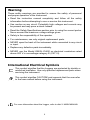
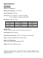
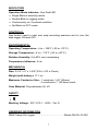
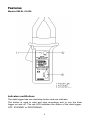
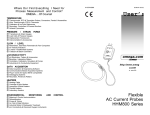
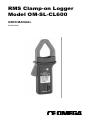
RMS Clamp-on Logger
Model OM-SL-CL600
USER MANUAL
M-3443/0899
WARRANTY/DISCLAIMER
OMEGA ENGINEERING, INC. warrants this unit to be free of defects in materials and workmanship for
a period of 13 months from date of purchase. OMEGA Warranty adds an additional one (1) month
grace period to the normal one (1) year product warranty to cover handling and shipping time. This
ensures that OMEGA's customers receive maximum coverage on each product.
If the unit should malfunction, it must be returned to the factory for evaluation. OMEGA's Customer
Service Department will issue an Authorized Return (AR) number immediately upon phone or written
request. Upon examination by OMEGA, if the unit is found to be defective it will be repaired or replaced
at no charge. OMEGA's WARRANTY does not apply to defects resulting from any action of the
purchaser, including but not limited to mishandling, improper interfacing, operation outside of design
limits, improper repair, or unauthorized modification. This WARRANTY is VOID if the unit shows
evidence of having been tampered with or shows evidence of being damaged as a result of excessive
corrosion; or current, heat, moisture or vibration; improper specification; misapplication; misuse or other
operating conditions outside of OMEGA's control. Components which wear are not warranted, including
but not limited to contact points, fuses, and triacs.
OMEGA is pleased to offer suggestions on the use of its various products. However, OMEGA
neither assumes responsibility for any omissions or errors nor assumes liability for any
damages that result from the use of its products in accordance with information provided by
OMEGA, either verbal or written. OMEGA warrants only that the parts manufactured by it will be
as specified and free of defects. OMEGA MAKES NO OTHER WARRANTIES OR
REPRESENTATIONS OF ANY KIND WHATSOEVER, EXPRESSED OR IMPLIED, EXCEPT THAT OF
TITLE, AND ALL IMPLIED WARRANTIES INCLUDING ANY WARRANTY OF MERCHANTABILITY
AND FITNESS FOR A PARTICULAR PURPOSE ARE HEREBY DISCLAIMED. LIMITATION OF
LIABILITY: The remedies of purchaser set forth herein are exclusive and the total liability of
OMEGA with respect to this order, whether based on contract, warranty, negligence,
indemnification, strict liability or otherwise, shall not exceed the purchase price of the
component upon which liability is based. In no event shall OMEGA be liable for consequential,
incidental or special damages.
CONDITIONS: Equipment sold by OMEGA is not intended to be used, nor shall it be used: (1) as a
"Basic Component" under 10 CFR 21 (NRC), used in or with any nuclear installation or activity; or (2) in
medical applications or used on humans. Should any Product(s) be used in or with any nuclear
installation or activity, medical application, used on humans, or misused in any way, OMEGA assumes
no responsibility as set forth in our basic WARRANTY/ DISCLAIMER language, and additionally,
purchaser will indemnify OMEGA and hold OMEGA harmless from any liability or damage whatsoever
arising out of the use of the Product(s) in such a manner.
RETURN REQUESTS/ INQUIRIES
Direct all warranty and repair requests/inquiries to the OMEGA Customer Service Department. BEFORE
RETURNING ANY PRODUCT(S) TO OMEGA, PURCHASER MUST OBTAIN AN AUTHORIZED
RETURN (AR) NUMBER FROM OMEGA'S CUSTOMER SERVICE DEPARTMENT (IN ORDER TO
AVOID PROCESSING DELAYS). The assigned AR number should then be marked on the outside of
the return package and on any correspondence.
The purchaser is responsible for shipping charges, freight, insurance and proper packaging to prevent
breakage in transit.
FOR WARRANTY RETURNS, please have the following
information available BEFORE contacting OMEGA:
1. P.O. number under which the product was
PURCHASED,
FOR NON-WARRANTY REPAIRS, consult
OMEGA for current repair charges. Have the
following information available BEFORE
contacting OMEGA:
2. Model and serial number of the product under
warranty, and
1. P.O. number to cover the COST of the repair,
3. Repair instructions and/or specific problems
relative to the product.
3. Repair instructions and/or specific problems
relative to the product.
2. Model and serial number of product, and
OMEGA's policy is to make running changes, not model changes, whenever an improvement is
possible. This affords our customers the latest in technology and engineering.
OMEGA is a registered trademark of OMEGA ENGINEERING, INC.
© Copyright 1996 OMEGA ENGINEERING, INC. All rights reserved. This document may not be copied,
photocopied, reproduced, translated, or reduced to any electronic medium or machine-readable form, in
whole or in part, without prior written consent of OMEGA ENGINEERING, INC.
Table of Contents
Warning ................................................................................................ 4
International Electrical Symbols............................................................. 4
Receiving Your Shipment...................................................................... 5
Packaging............................................................................................. 5
Specifications........................................................................................ 6
Features ............................................................................................... 8
Indicators and Buttons ....................................................................... 8
Inputs and Outputs ............................................................................ 9
Battery Installation ............................................................................. 9
Operation.............................................................................................10
Software ..............................................................................................10
Minimum Computer Requirements....................................................10
Installation........................................................................................10
Using The Software ..........................................................................11
Cleaning ..............................................................................................11
3
Warning
These safety warnings are provided to ensure the safety of personnel
and proper operation of the instrument.
• Read the instruction manual completely and follow all the safety
information before attempting to use or service this instrument.
• Use caution on any circuit: Potentially high voltages and currents may
be present and may pose a shock hazard.
• Read the Safety Specifications section prior to using the current probe.
Never exceed the maximum voltage ratings given.
• Safety is the responsibility of the operator.
• For maintenance, use only original replacement parts.
• NEVER open the back of the instrument while connected to any circuit
or input.
• Replace any defective parts immediately.
• NEVER use the Model OM-SL-CL600 on electrical conductors rated
above 600 V in overvoltage category III (CAT III).
International Electrical Symbols
This symbol signifies that the Loggers are protected by double or
reinforced insulation. Use only specified replacement parts when
servicing the instrument.
This symbol signifies CAUTION! and requests that the user refer
to the user manual before using the instrument.
For more information about the Logger, refer to disk 2: MAIN MANUAL
4
Receiving Your Shipment
Upon receiving your shipment, make sure that the contents are
consistent with the packing list. Notify OMEGA of any missing items. If
the equipment appears to be damaged, file a claim immediately with the
carrier and notify OMEGA at once, giving a detailed description of any
damage.
Packaging
The Model OM-SL-CL600 includes the following:
• User manual
• One 9 V battery
• Two 3½” disks containing the window-based download and graphic
software and a generic user manual
• Six ft. long RS232 cable
5
Specifications
ELECTRICAL
Number of Channels: 1
Measurement Range: 0 to 600 Arms
Input Connection: Split jaw
*Accuracy: 2% of readings + resolution (0-400A)
5% of readings + resolution (400-600A)
Resolution : 8 Bit (0.5 Arms)
Scale Range
Maximum Input
Resolution
100%
600 Arms
4 Arms
50%
500 Arms
2 Arms
25%
250 Arms
1 Arms
12.5%
125 Arms
0.5 Arms
Sample Rate:
4096/hr max; decreases by 50% each time memory is full
Data Storage: 8192 readings
Data Storage Technique: TXR™ Time Extension Recording™
Power: 9V Alkaline NEDA 1604, 6LF22, 6LR61
Battery Life Recording:
Up to 1 year continuous recording @ 25°C
Output: RS-232 via DB9 connector
*Reference condition: 23°C ± 3K, 20 to 70% RH, Frequency 50/60Hz, No AC
external magnetic Field, DC magnetic field ≤ 40A/m, centered conductor, battery
voltage 9 V ± 10%.
6
INDICATORS
Operation Mode Indicator: One Red LED
• Single Blink in stand-by mode
• Double Blink in logging mode
• Continuously on: Overload condition
• No Blinks in OFF mode
CONTROLS:
One button used to start and stop recording sessions and to turn the
data logger ON and OFF.
ENVIRONMENTAL
Operating Temperature: -4 to + 158°F (-20 to +70°C)
Storage Temperature: -4 to + 174°F (-20 to +80°C)
Relative Humidity: 5 to 95% non-condensing
Temperature Influence: 5 cts.
MECHANICAL
Size: 9-1/4" x 4" x 1-5/8" (235 x 102 x 41mm)
Weight (with battery): 17.1 oz.
Maximum Conductor Size: 1 conductor 1.65” (42mm)
2 conductors 1” (25.4mm) each
Case Material: Polycarbonate UL V0
SAFETY
Working Voltage: IEC 1010-1, 600V, Cat III
ORDERING INFORMATION
RMS Clamp-On Logger ........................................ Model OM-SL-CL600
7
Features
Models OM-SL-CL600:
Indicators and Buttons
The data logger has one start/stop button and one indicator.
The button is used to start and stop recordings and to turn the data
logger on and off. The red LED indicates the status of the data logger;
OFF, STANDBY or RECORDING.
8
Inputs and Outputs
Input to the logger is via a split jaw CT. The bottom of the data logger
has a female 9 pin “D” shell serial connector used for data transmission
from the data logger to your computer.
Battery Installation
Under normal conditions, the battery will last up to a year of continuous
recording unless the logger is re-started very frequently.
In the OFF mode, the logger puts almost no load on the battery. Use the
OFF mode when the logger is not in use. Replace the battery once a
year in normal use.
If the logger will be used at temperatures below 32°F (0°C) or is
frequently turned on and off, replace the battery every six to nine
months.
1. Make sure your logger is turned off (no light blinking) and all
inputs are disconnected.
2. Turn the data logger upside down. Unscrew the battery
compartment.
3. Locate the two wire (red/black) battery connector and attach the
9 V battery to it. Make sure that you observe polarity by lining up
the battery posts to the proper terminals on the connector.
4. Once the connector is plugged onto the battery, insert the battery
into the battery compartment.
5. Close the battery compartment.
Your data logger is now recording (LED blinking). Press the test button
for 5 seconds to stop the instrument
Note: For long term storage, remove the battery to prevent discharge
effects.
9
Operation
Position the Model CL600 around the conductor to be measured. Be
sure that the positioning of the CL600 allows the jaws to firmly close
before beginning the recording session.
Next, press the start/stop button on the front of the unit to begin the
recording session. The indicator light will double blink to indicate that the
recording session has started. When the recording session has been
completed, press the start/stop button to end the recording. The indicator
light will single blink to indicate that the recording session has ended and
the unit is in stand-by. Remove the logger from the conductor and
transport it to the computer for data downloading. See section 2 page 19
of the main manual for downloading.
Note: If the LED is continuously lit. You are measuring a current
above 600A. Unclamp the probe immediately.
Software
MINIMUM COMPUTER REQUIREMENTS
Processor: 386 or higher
RAM Storage: 4 MB minimum
Hard Drive Space:
100K for application, approximately 200K for each stored file
Environment: Windows 3.1 or Windows 95
Port Access: 1 available 9 pin serial port
1 parallel port for printer support
INSTALLATION
Your data logger software is supplied on a single 3½” floppy disk. To
install the program on your Windows based computer, proceed as
follows: The software is Multilanguage. A prompt will ask you to select
the language at the end of the installation process.
Windows 3.1 Systems
1. Insert the floppy disk containing the data logger software in your
computer’s floppy drive (usually Drive A).
2. From the Program Manager select “File” on the command line.
3. Select “Run” from the pull-down menu and type a:setup in the
dialog box then click on “OK”.
10
4. The set up program will temporarily load onto your computer.
5. Next the setup program will offer C:\DATALOG as location where
the software will be installed. Click on “Next” to use this directory or
type in a new name, then click on “Next”.
6. A bar graph will appear showing the progress of installation. When
installation is complete a message screen will appear stating that
the program has been installed. Click on “OK”. You are now ready
to use the data logger software.
Windows 95 Systems
1. Insert the floppy disk containing the data logger software in your
computer’s floppy drive (usually Drive A).
2. Click on the “Start” button on the bottom left side of the screen.
3. Select “Run” from the menu and type a:setup in the dialog box then
click on “OK”.
4. The setup program will temporarily load onto your computer.
5. Next the setup program will offer C:\DATALOG as location where
the software will be installed. Click on “Next” to use this directory or
type in a new name, then click on “Next”.
6. A bar graph will appear showing the progress of installation. When
installation is complete a message screen will appear stating that
the program has been installed. Click on “OK”. You are now ready
to use the data logger software.
USING THE SOFTWARE
Launch the software and connect the RS232 cable from your computer
from the logger.
Select “FILE”, “Baud rate” and “1200”, then select “PORT”, Com1, Com2,
Com3 or Com4 (see your computer manual). The logger must now
communicate with your computer (ID number of the logger and number
of points recorded displayed).
Select download to display the graph. (Download takes about 90
seconds)
Cleaning
The body of the clamp should be cleaned with a cloth moistened with
soapy water. Rinse with a cloth moistened with clean water. Do not use
solvent.
11
OMEGAnetSM On-Line Service: http://www.omega.com
Internet e-mail: [email protected]
Servicing North America:
USA:
ISO 9001 Certified
Canada:
One Omega Drive, Box 4047
Stamford, CT 06907-0047
Tel: (203) 359-1660
e-mail: [email protected]
976 Bergar
Laval (Quebec) H7L 5A1
Tel: (514) 856-6928
e-mail: [email protected]
FAX: (203) 359-7700
FAX: (514) 856-6886
For Immediate Technical or Application Assistance:
USA and Canada:
Sales Service: 1-800-826-6342 1-800-TC-OMEGASM
Customer Service: 1-800-622-2378 / 1-800-622-BESTSM
Engineering Service: 1-800-872-9436 / 1-800-USA-WHENSM
TELEX: 996404 EASYLINK 62968934 CABLE: OMEGA
Mexico and
Latin America:
Tel: (95) 800-TC-OMEGASM
En Espanol: (203) 359-1660 ext: 2203
Benelux:
Postbus 8034,1180 LA Amstelveen, The Netherlands
Tel: (31) 20 6418405
FAX: (31) 20 6434643
Toll Free in Benelux: 06 0993344
e-mail: [email protected]
Czech Republic:
Ostravska 767, 733 01 Karvina
Tel: 420 (69) 6311899
FAX: 420 (69) 6311114
e-mail: [email protected]
France:
9, rue Denis Papin, 78190 Trappes
Tel: (33) 130-621-400
FAX: (33) 130-699-120
Toll Free/France: 0800-4-06342 e-mail: [email protected]
Germany/Austria:
Daimlerstrasse 26, D-75392 Deckenpfronn, Germany
Tel: 49 (07056) 3017
FAX: 49 (07056) 8540
Toll Free in Germany: 0130 11 21 66
e-mail: [email protected]
United Kingdom:
25 Swannington Road,
Broughton Astley, Leicestershire,
LE9 6TU, England
Tel: 44 (1455) 285520
FAX: 44 (1455) 283912
Toll Free in England: 0800-488-488
FAX: (95) 203-359-7807
e-mail: [email protected]
Servicing Europe:
150 9002 Certified
P.O. Box 7, Omega Drive,
Irlam, Manchester,
M44 5EX, England
Tel: 44 (161) 777-6611
FAX: 44 (161) 777-6622
e-mail: [email protected]
It is the policy of OMEGA to comply with all worldwide safety and EMC/EMI regulations that apply.
OMEGA is constantly pursuing certification of its products to the European New Approach Directives.
OMEGA will add the CE mark to every appropriate device upon certification.
The information contained in this document is believed to be correct but OMEGA Engineering, Inc.
accepts no liability for any errors it contains, and reserves the right to alter specifications without notice.
WARNING: These products are not designed for use in, and should not be used for, patient connected
applications.
Where Do I Find Everything I Need for
Process Measurement and Control?
OMEGA ... Of Course!
TEMPERATURE
ο3
ο3
ο3
ο3
ο3
Thermocouple, RTD & Thermistor Probes, Connectors, Panels & Assemblies
Wire: Thermocouple, RTD & Thermistor
Calibrators & Ice Point References
Recorders, Controllers & Process Monitors
Infrared Pyrometers
PRESSURE / STRAIN FORCE
ο3
ο3
ο3
ο3
Transducers & Strain Gauges
Load Cells & Pressure Gauges
Displacement Transducers
Instrumentation & Accessories
FLOW / LEVEL
ο3
ο3
ο3
ο3
Rotameters, Gas Mass Flowmeters & Flow Computers
Air Velocity Indicators
Turbine / Paddlewheel Systems
Totalizers & Batch Controllers
pH/CONDUCTIVITY
ο3
ο3
ο3
ο3
pH Electrodes, Testers & Accessories
Benchtop / Laboratory Meters
Controllers, Calibrators, Simulators & Pumps
Industrial pH & Conductivity Equipment
DATA ACQUISITION
ο3
ο3
ο3
ο3
ο3
Data Acquisition & Engineering Software
Communications-Based Acquisition Systems
Plug-in Cards for Apple, IBM & Compatibles
Datalogging Systems
Recorders, Printers & Plotters
HEATERS
ο3
ο3
ο3
ο3
ο3
Heating Cable
Cartridge & Strip Heaters
Immersion & Band Heaters
Flexible Heaters
Laboratory Heaters
ENVIRONMENTAL MONITORING AND CONTROL
ο3
ο3
ο3
ο3
ο3
Metering & Control Instrumentation
Refractometers
Pumps & Tubing
Air, Soil & Water Monitors
Industrial Water & Wastewater Treatment
ο3 pH, Conductivity & Dissolved Oxygen Instruments
14