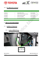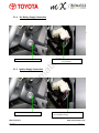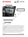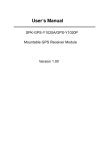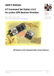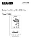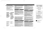
1
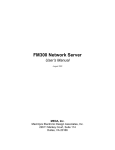
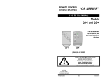
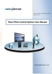
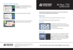
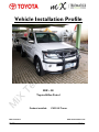
Vehicle Installation Profile
MIX – 3E
Toyota Hillux Petrol
Product installed:
MiX Telematics
MIX -3E Rev-1
FM3310i Tracer
www.mixtelematics.com
Page 1 of 21
Approval Internal:
Company
Revision
1
Author
Wayne Barnard
MiX Telematics
Reviewer
Riaan Barnard
MiX Telematics
Approved by
Riaan Barnard
MiX Telematics
MiX Telematics
MIX -3E Rev-1
Position
OEM Technical
Consultant
Technical Manager
RSA/Africa Support
Technical Manager
RSA/Africa Support
Date
23-06-2009
23 June 2009
23 June 2009
www.mixtelematics.com
Page 2 of 21
TABLE OF CONTENT
PAGE NUMBER
1.
ADENDUM / REVISION ..................................................... 5
2.
FITMENT REQUIREMENT AS PER CLIENT .................... 6
3.
INTRODUCTION................................................................ 6
3.1.
Purpose of the Documents.......................................................................................... 6
3.2.
Validity of the Document ............................................................................................. 6
3.3.
Definitions, Terms and Abbreviations ....................................................................... 6
3.4.
Relationship with Other Documents .......................................................................... 6
3.5.
General Installations Practices ................................................................................... 7
4.
MATERIAL LIST FOR INSTALLATION ............................ 8
4.1.
Tools Required ............................................................................................................. 8
4.2.
Consumables Required (Special Pins etc.) ............................................................... 8
4.3.
Component Breakdown ............................................................................................... 9
4.3.1.
4.4.
5.
FM3310i Tracer .......................................................................................................... 9
Bill of Material Recommended .................................................................................. 10
INSTALLATION PROCEDURE ....................................... 10
5.1.
Installation of Components ....................................................................................... 10
5.1.1.
Location of FM3310i Tracer ..................................................................................... 10
5.1.2.
Location of GPS Antenna ........................................................................................ 11
5.1.3.
Location of GSM Antenna ........................................................................................ 11
5.1.4.
12v Battery Supply Connection................................................................................ 12
5.1.5.
Ignition Supply Connection ...................................................................................... 12
5.1.6.
Chassis Ground Connection .................................................................................... 13
5.1.7.
Starter Interrupt ........................................................................................................ 13
MiX Telematics
MIX -3E Rev-1
www.mixtelematics.com
Page 3 of 21
5.1.8.
RPM Connection ...................................................................................................... 14
5.1.9.
Speed Connection ................................................................................................... 14
5.1.10. Download Socket Location ...................................................................................... 15
6.
COMPONENT SPECIFICATIONS ................................... 15
6.1.
6.1.1.
7.
FM3310i Tracer Fact Sheet ........................................................................................ 15
FEATURES .............................................................................................................. 16
COMMISSIONING PROCEDURES ................................. 19
7.1.
Vehicle Calibration Procedures ................................................................................ 19
7.1.1.
Rpm Calibration ....................................................................................................... 19
7.1.2.
Speed Calibration .................................................................................................... 19
7.2.
Vehicle Testing ........................................................................................................... 20
7.3.
MiX Telematics Control Centre Procedures ............................................................ 20
7.4.
Completion of Documentation .................................................................................. 21
MiX Telematics
MIX -3E Rev-1
www.mixtelematics.com
Page 4 of 21
1. ADENDUM / REVISION
Revision No:
Description
Date
MIX -3E Rev-1
Signatures
MiX Telematics
MiX Telematics
www.mixtelematics.com
Page 5 of 21
2. FITMENT REQUIREMENT AS PER CLIENT
The onboard computer unit is required to monitor:
Driver performance.
Vehicle Utilisation.
Driver Identification.
Vehicle Tracking.
3. INTRODUCTION
3.1.
Purpose of the Documents
The document is designed to provide a guide for the Installation of the FM3310i Tracer, a product of MiX
Telematics (Pty) Ltd, into the specific vehicle make and model. The installation guide assumes that the installer has
attended the relevant Training Course and is familiar to the FM product specification and is qualified to work on the
vehicle electrical systems.
3.2.
Validity of the Document
The document relates only to the installation of the products referred to in clause 4.4 (Bill of Materials) and to the
fitment instructions related to the vehicle make and model and should only be used as such. The document
provides the guidance and represents the Vehicle Manufacturer (OEM) specifications for the installation of the
product only.
3.3.
Definitions, Terms and Abbreviations
FM
-
Fleet Management
GPS
-
Global Positioning System
GSM
-
Global System for Mobile Communications
3.4.
Relationship with Other Documents
The following documents are related to or are used as reference for this document.
FM3310i Tracer Installation Manual
FM3310i Tracer Fact Sheet
MiX Telematics
MIX -3E Rev-1
www.mixtelematics.com
Page 6 of 21
3.5.
General Installations Practices
The installation of any MiX Telematics products needs to adhere to the following guidelines in the order not to avoid
Vehicle Manufacturer Warranty:
•
All wire connections must be soldered and insulated correctly.
•
DO NOT leave wires un-strapped and un-sleeved.
•
DO NOT attach or strap wires and components on any Airbag Components.
•
ENSURE that the FM unit is securely fitted or mounted. USE double sided tape to prevent movement to the
FM Unit.
•
DO NOT install the GSM antenna on any metal surface. ONLY install the GSM antenna in a vertical up
position.
•
DO NOT install the GPS antenna under any metal surface.
•
Lead the wiring through existing GROMMETS if the wiring needs routed through the firewall and ensure
that the grommet has a watertight seal.
•
Familiarize yourself with specific procedures to remove and replace a vehicle dashboard and the tension
required on all dashboard screws.
MiX Telematics
MIX -3E Rev-1
www.mixtelematics.com
Page 7 of 21
4. MATERIAL LIST FOR INSTALLATION
4.1.
Tools Required
Description
4.2.
1
Phillips Screw Driver
2
Flat Screw Driver
3
Side Cutter Pliers
4
Crimper Pliers
5
Socket Set (Sizes 8-22)
6
Spanner Set (Sizes 8-22)
7
Soldering Iron
8
Multi Meter
Consumables Required (Special Pins etc.)
Description
1
Insulation Tape
2
Cable Ties 150mm
3
Cable Ties 205mm
4
Double sided tape
5
Ring Terminal
6
Solder 0.75mm
MiX Telematics
MIX -3E Rev-1
www.mixtelematics.com
Page 8 of 21
4.3.
Component Breakdown
4.3.1.
FM3310i Tracer
Description
MiX Telematics
MIX -3E Rev-1
1
FM3310i Tracer-Battery
2
FM300 Main Harness
3
FM300 Code Plug Socket Extension
4
Code Plug Socket
5
Blue Driver ID Tag
6
GSM Antenna
7
GPS Antenna
www.mixtelematics.com
Page 9 of 21
4.4.
Bill of Material Recommended
Part Number
Qty.
Description
Supplier
450FT0502
1
FM3310i Tracer
MiX Telematics
440FT0171
1
FM300 Main Harness
MiX Telematics
440FT0166
1
FM300 Code Plug Socket Extension
MiX Telematics
440FT0034
1
FM300 Code Plug Socket
MiX Telematics
440FT0073
1
FM Driver Plug (blue)
MiX Telematics
440FT0198
1
GPS Antenna FM Comm.
MiX Telematics
440FT0197
1
GSM Antenna FM Generic
MiX Telematics
5. INSTALLATION PROCEDURE
5.1.
Installation of Components
5.1.1.
Location of FM3310i Tracer
FM 3310i Unit needs
to be installed driver
side
behind
the
bottom right side
cover.
MiX Telematics
MIX -3E Rev-1
www.mixtelematics.com
Page 10 of 21
5.1.2.
Location of GPS Antenna
Place unit on top of the vent behind
the cluster with a strip of strong double
sided tape. Location gives you the
best view for the GPS to pick up
satellites.
5.1.3.
Location of GSM Antenna
GSM needs to be installed in a vertical position.
Can be installed behind the left side of the
cluster.
MiX Telematics
MIX -3E Rev-1
www.mixtelematics.com
Page 11 of 21
5.1.4. 12v Battery Supply Connection
Take off the bottom steering cover.
Black wire with a Red trace on the IGN Key is
a 12 volt supply
5.1.5. Ignition Supply Connection
Take off the bottom steering cover.
MiX Telematics
MIX -3E Rev-1
BLACK wire with a yellow trace on the IGN Key
is a 12 volt ignition supply
www.mixtelematics.com
Page 12 of 21
5.1.6.
Chassis Ground Connection
Take out the cluster.
5.1.7.
Starter Interrupt
Take off the bottom steering cover.
MiX Telematics
MIX -3E Rev-1
Use a Ring terminal on this 10mm mounting nut.
Use the Black with white trace for starter interrupt.
www.mixtelematics.com
Page 13 of 21
5.1.8.
RPM Connection
White plug behind cluster, use Black
with White trace.
5.1.9.
Speed Connection
White plug behind cluster, use Pink
with grey dots for speed pick up.
MiX Telematics
MIX -3E Rev-1
www.mixtelematics.com
Page 14 of 21
5.1.10.
Download Socket Location
Use one of the blank plugs on the right
hand side to mount your code plug
socket.
6. COMPONENT SPECIFICATIONS
6.1.
FM3310i Tracer Fact Sheet
OVERVIEW
The FM3310i Tracer offers extensive driver and vehicle management and has an additional internal GPS receiver
and GSM/GPRS modem. The GPS receiver allows the recording of GPS position information, enabling you to
determine the movement history of the vehicles. The GPS receiver in conjunction with the GSM/GPRS modem
allows active tracking of vehicles enabling you to request their position at any time. In addition the GSM/GPRS
modem enables you to receive real-time notifications of user specified events such as the time arrived at a
specified location. Remote data upload and download to and from your FM3310i Tracer with the GSM/GPRS
Modem, ensures that data transfer does not interfere with the daily activities of the fleet. An optional voice kit that
receives incoming calls ensures the driver remains focused on the road, contributing to enhanced communication
and safety. Security concerns are addressed with the provision of an optional battery backup that allows
uninterrupted communication with the Fleet Manager Software even if the unit’s power is cut.
MiX Telematics
MIX -3E Rev-1
www.mixtelematics.com
Page 15 of 21
6.1.1.
FEATURES
LOCATION MANAGEMENT
•
Active/ Passive Tracking or Active Trail:
Request the vehicle position in real-time or view the route taken after the trip has been downloaded. Active
Trail allows hourly updating of the Fleet Manager software with GPS vehicle positions.
•
GPS Data Recording:
Various information is recorded with every GPS point, e.g. vehicle and driver ID, date and time, latitude and
longitude, altitude, heading, velocity, number of satellite etc.
•
Manage Locations:
Add any desired location such as customer, supplier or no- go zones.
•
Route Planning:
Plan routes by entering stops, start times and duration of each stop. This can serve as daily job activity
sheets for your drivers.
•
Active Events:
Receive data messages such as SMS when selected standard or user-defined events occur, e.g. a cargo
door opening in a no-go zone, driver arrived at customer location.
COMMUNICATION
•
Downloading to / uploading from vehicle:
Use the GSM/GPRS Modem to download data to and upload data from the FM3310i Tracer. The modem
also enables active tracking of the FM3310i Tracer by the Fleet Manager Software.
•
Voice Calls:
Incoming voice calls are possible with an optional headset.
VEHICLE AND DRIVER MANAGEMENT
•
Trip Data Recording:
The following data is recorded: date and time, distance travelled, journey duration, vehicle speed, engine
speed (RPM), journey departure and arrival time, driver name, driver ID, vehicle ID.
•
Driving Violations:
The following standard violations are recorded: over speeding, over revving, green band driving, harsh
braking, harsh acceleration, excessive idling and overtime driving.
•
Customized Events:
Define customized events, such as driver door opening, no-go zone entered, hazard lights activated and
refrigerator temperature exceeded.
•
Second-to-Second (Tacho) Data:
MiX Telematics
MIX -3E Rev-1
www.mixtelematics.com
Page 16 of 21
The status of inputs such as speed and RPM is recorded every second. This provides valuable in-depth
information for accident analysis.
•
Servicing and Licensing:
Set reminders for your vehicle’s next service or for your vehicle/driver license expiry.
•
Driver Identification & Immobilization:
Use a driver tag to identify the driver. A default driver can be assigned to a vehicle. An immobilizer function
ensures the car only starts if an authorized driver inserts his driver tag.
•
Warning Buzzer:
Set a warning buzzer to sound when driving violations or events take place.
ACTIVE TRACKING
The internal GPS receiver and GSM/GPRS modem allow active tracking of the FM3310i Tracer. You are able to
locate and track your vehicles precisely in real-time. The Fleet Manager software uses either the GSM Short
Message Service (SMS) or the GPRS connection to deliver the real-time information to you.
With active tracking, you can track the current position of your vehicles, locate a vehicle closest to a customer
location, or view the trail as the vehicle moves. In addition all vehicle location positions are stored in the on-board
computer and can be used for historical or passive tracking.
COMMUNICATION
The FM3310i Tracer allows incoming voice calls where a headset, keypad and cable are connected to the on-board
computer (OBC). This allows the drivers to safely communicate over a head-set, allowing them to focus on the
road. The FM3310i Tracer is compatible with the Falcom A2-FSE02 Hands Free Unit.
Battery Backup (Optional)
Optional Battery Backup is available if you would like more security. The Battery Backup starts to operate as soon
as the supply to the battery is cut. The battery backup is supplied by a Hi Temp NiMH Battery Pack. The backup
time is a minimum of 4 hours, when the GSM/GPRS is active in low power mode and the GPS is disabled.
ACTIVATION MANAGEMENT
The unit can be configured to switch itself off. In the switched-off state the unit will only power-up when the ignition
line is switched on. Thereafter it will abide by the conditions defined by the unit configuration.
TECHNICAL INFORMATION
•
8 configurable analogue or digital inputs:
Configured to monitor any device that generates a change in voltage, e.g. seat belts, headlights,
refrigeration units, emergency lights, doors, PTO, UDS, trailer coupling etc.
MiX Telematics
MIX -3E Rev-1
www.mixtelematics.com
Page 17 of 21
•
3 auxiliary frequency inputs:
Configured to monitor any device that generates a change in frequency e.g. temperature sensor, liquid flow
measurement or as a pulse counter e.g. electronic fuel consumption measurement (EDM). A fourth
auxiliary input is connected to the internal GPS receiver.
•
1 Auxiliary relay drive:
Used to switch a relay with a current consumption of up to 150 mA.
•
2 Serial interface (1x RS232 and 1x TTL):
Connected to any TTL or RS232 serial device using the FM Serial cable (e.g. FM Terminal).
•
Ignition input:
Used to monitor the ignition switch status.
•
Positive drive output:
Used to power external devices. It can supply current up to 500mA.
•
Buzzer output:
Signaling device
•
Audio interface:
This interface allows the user to make voice calls using a headset, keypad and cable.
THE FM3310I TRACER INCLUDES:
•
Electronic Module with integrated GSM/GPRS module.
•
GSM/GPRS Antenna.
•
GPS Antenna.
•
Main harness with integrated buzzer (2x frequency input, 3x digital/analogue input).
•
FM300 code plug-harness including vehicle interface.
•
Blue driver’s key (driver log-on).
•
FM on-board computer user manual.
•
Optional harnesses: I/O harness (2x frequency input, 4x digital/analogue input), serial harness, voice
harness.
SOFTWARE
Fleet Manager Professional 9 provides the serious fleet operator with extensive fleet management tools to manage
and report on his fleet. The software enables you to manage vehicle, driver and passenger information, define and
manage events to be monitored, analyze fleet data and do extensive management reporting. In addition to the core
software, Fleet Manager Professional 9 also offers a set of extensions that allow additional monitoring and
reporting on the fleet. Our Internet Bureau Service, FM-Web, also supports the FM3310i Tracer.
MiX Telematics
MIX -3E Rev-1
www.mixtelematics.com
Page 18 of 21
7. COMMISSIONING PROCEDURES
7.1.
Vehicle Calibration Procedures
7.1.1.
•
•
•
•
•
•
Rpm Calibration
Start the vehicle by inserting the driver tag and follow the below procedure to calibrate speed.
While the vehicle is idling, insert the 128b violet tag, the unit will beep in ½ second pulses,
Set the Rpm calibration tag to 1000 or 2000 Rpm.
Rev the vehicle to 1000Rpm or 2000Rpm, to compensate for the 100 rpm deduction rule, hold it there for 3
seconds, then immediately remove the Rpm calibration tag, wait another 3 seconds before releasing the
accelerator pedal.
You will hear x3 audible beeps from the OBC to confirm that it has picked up the rpm pulses from the
vehicle.
Switch off vehicle. Wait for the OBC to arm after 30 seconds, to be able to do the speed calibration as the
next step.
7.1.2. Speed Calibration
•
•
•
•
•
•
•
•
•
•
•
•
•
•
•
•
•
•
The vehicle test trip needs to exceed a distance of around 5 km or a travel time, including idling time of
around 15 minutes. The FM unit will download once the vehicle ignition is switched off;
The vehicle must be manually calibrated over a 1km measured distance or by Odo meter of the cluster.
The calibration procedure must include the following:
Ensure that the measured distance is marked using a measuring wheel.
Stop the vehicle on the starting line for the 1km distance, switch off the vehicle and wait for 30 seconds for
the OBC to arm, you will x1 audible beep, then the OBC is armed.
Insert the driver tag to disarm the OBC, you will hear x2 audible beeps, start vehicle immediately before 30
seconds.
Start the vehicle and insert the speed calibration tag (128b Violet tag).
Reset the odometer of the vehicle as well to use as a reference for the distance.
Immediately when the FM3310i Tracer starts beeping in ½ second pulses, then start driving the vehicle for
the duration of the 1km at a constant speed of 60km per hour.
Gently stop the vehicle when you have reached the end of the 1km distance, remove the speed calibration
tag, you should hear x3 audible beeps which will notify you that the speed pulses have been picked up by
the OBC and everything has tested ok.
Important: If you do not hear the x3 audible beeps after immediately removing the speed calibration
tag, check the speed input wire from the vehicle to see if it is connected properly, or if it is the right
wire from the vehicle.
Also check if the vehicles speed sender is operational and there are pulses present.
Switch off the vehicle and wait for 30 seconds for the vehicle to arm, you will x1 audible beep, and then the
vehicle is armed.
Insert the driver tag to disarm the unit, wait for x2 audible beeps to notify you that the OBC has disarmed.
Drive the vehicle for another 1km measured distance at a constant speed of 60km per hour.
Gently stop the vehicle at the end of the 1km measured distance,
Rev the vehicles engine to 2000Rpm, when you reach 2000Rpm, keep it constant for 3seconds, and then
release the accelerator.
Switch off the vehicle, write down the time after switching the vehicle, write down the odometer reading of
the vehicle,
MiX Telematics
MIX -3E Rev-1
www.mixtelematics.com
Page 19 of 21
•
7.2.
•
Contact the Cape Town MiX Telematics response center and issue them with the odometer reading and
the test trip time.
Vehicle Testing
The vehicle test trip needs to exceed a distance of around 5 km or a travel time, including idling time of
around 15 minutes. The FM unit will download once the vehicle ignition is switched off;
•
7.3.
•
The vehicle ODO reading must be updated to MiX Telematics Response Centre.
MiX Telematics Control Centre Procedures
Ensure that the job instruction is clearly understood according to the Purchase Order. Contact MiX
Telematics Response Centre on 0860 103 834 if the job instruction is not clear.
•
Once the technician arrives on site or is at the vehicle as specified on the Purchase Order, the technician
must contact the Response Centre to book onto the job.
•
The relevant portion of the Pre-post work checklist supplied by MiX Telematics must be completed and
signed by the customer or customer representative prior to commencement of the installation.
•
Complete the installation/maintenance according to work instructions on the MiX Telematics Purchase
Order.
•
Calibrate the speed and RPM with the speed and RPM calibration tags.
•
Check the GPS module with the GPS diagnostic tag.
•
Check the GSM modem with the GSM diagnostic tag.
•
Contact the Response Centre and request an upload of the unit configuration. Ensure that you have the
unit serial number, data number, SIM card number, unit ID, Call number, vehicle make, model and
registration at hand.
•
A Response Centre agent will contact you to confirm that the upload has been successful.
•
Complete a test trip with a speed no less than 60 km/h and record the maximum speed and RPM during
the test trip.
•
Test or simulate all inputs connected at the end of the test trip.
•
Contact the Response Centre and supply them with the information recorded during the test trip (including
ODO reading) and instruct them to do a download.
•
A Response Centre agent will contact you to confirm that all the recorded information was correct
according to the information you supplied and that all inputs are showing correctly. You will be instructed to
redo the calibrations and complete another test trip if the information supplied was not recorded by the unit.
•
A test reference number will be issued to by a Response Centre agent if the unit recorded the test trip
correctly.
MiX Telematics
MIX -3E Rev-1
www.mixtelematics.com
Page 20 of 21
•
The relevant portion of the Pre-post work checklist supplied by MiX Telematics must be completed and
signed by the customer or customer representative upon the completion of the installation and
commissioning.
7.4.
Completion of Documentation
The following completed documents should be signed by the technician and the client:
A Dealer Job card including the MiX Telematics test reference number.
MiX Telematics
MIX -3E Rev-1
www.mixtelematics.com
Page 21 of 21