1
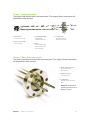
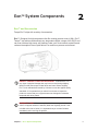
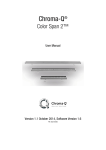
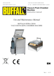
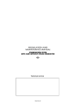
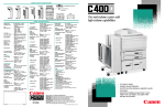
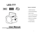
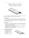
Tempe
TM
self-heating QCM
user guide
2nd generation
Contents
4
5
5
Chapter 1: Tempe™ Sensor at a Glance
6
6
10
Chapter 2: Eon System™ Components
12
12
14
14
Chapter 3: Eon™ Inputs & Outputs
15
15
18
19
Chapter 4: Hardware Connections
21
21
22
24
Chapter 5: Electronics Connections
26
26
27
Chapter 6: Troubleshooting
29
29
30
Chapter 7: Specifications
Tempe™ Subcomponents
Tempe™ Base Subcomponents
Eon™ and Accessories
Mirage™ Air-Cooling System
Eon™ Connectors
Eon™ Inputs
Eon™ Outputs
Preparing Tempe™ for Chamber
Chamber Installation
Connecting to Tempe™
Connecting Tempe™ and Eon™
Connecting Hardware and Electronics
Connecting Eon™ to PC
Troubleshooting
Advanced Troubleshooting
Hardware
Electronics
Contents
2
Contents
31
31
Appendix A: Tempe-Eon™ System
32
33
33
33
Appendix B: Safety, Handling, & Support
35
Appendix C: Tooling Factor
36
Appendix D: Tempe™ Dimensions
37
Index
Contents
Tempe-Eon™ System Configuration
About Tempe™
Inspection & Initial Setup
Warranty
3
Tempe™ at a Glance
1
This guide discusses assembly and proper care and handling of Tempe™
(2nd generation) sensor with temperature control.
inspect product condition on arrival Examine Tempe™ for
any signs of physical damage that may have occured during shipping.
Make sure that the tamper-evident labels are intact. Before shipping,
Tempe™ was calibrated and tested by Colnatec to meet the highest
quality standards. It is important that you take a few minutes to inspect
the product to ensure that your equipment was not damaged or otherwise
tampered with during transit.
Chapter 1
Tempe™ at a Glance
4
Tempe™ Subcomponents
The sensor head features many sub-components. The usage of these components will
be detailed in later sections.
5
2
3
1
5
4
1. Sensor Head
Houses quartz crystal
2. Heater Control Cable
Controls heater
5. Cooling Tubes
Circulates forced air
through sensor head
3. Crystal Signal Cables
Relays crystal
oscillation information
4. Flange
Acts as nearly air-tight
barrier sealing sensor
head in chamber
Tempe™ Base Subcomponents
The sensor head features many base sub-components. The usage of these components
will be detailed in later sections.
1. SMA Coaxial Connection
For crystal frequency
measurement
2. LEMO Connection
For heater control
3. Cooling Tubes
Channels cool air into sensor
head
1
2
3
3
Chapter 1
Tempe™ at a Glance
Warning Extremely hot
air exiting ehaust line when
Mirage™ is active
5
Eon™ System Components
2
Eon™ and Accessories
Tempe-Eon™ ships with a variety of accessories.
Eon™. Designed for high temperature thin film coating process control. With Eon™,
Tempe™ can achieve and maintain any temperature within a range of 40-500ºC and
can even initiate a high-temp, self-cleaning “bake cycle” that extends crystal life and
reduces interruptions from crystal failure in a continuous process environment.
inspect product condition on arrival Examine Eon™ for
any signs of physical damage that may have occured during shipping.
Make sure that the tamper-evident labels are intact. Before shipping,
Eon™ was calibrated and tested by Colnatec to meet the highest quality
standards. It is important that you take a few minutes to inspect the
product to ensure that your equipment was not damaged or otherwise
tampered with during transit.
warranty label If the warranty label has been tampered with,
“VOID” will appear where the warranty label was originally placed. If this
is visible at the time of arrival, it is important that you contact Colnatec
immediately after receiving the product.
Chapter 2
Eon™ System Components
6
Mirage™ air-cooling system. As part of the Eon™ temperature-compensation
system, this cooling accessory channels compressed, cold air into the Tempe™
sensor in order to maintain consistent temperatures inside crystal compartment.
Mirage power adapter. Combines Mirage™ power supply and relay cables.
Mirage air-cooling tube. Delivers cold air into sensor head cooling tubes.
Chapter 2
Eon™ System Components
7
Power supply and cable. Input 100-200 VAC, 50/60Hz, 2 A. Output 24V, 3.75 A,
90W Max.
RS-232 extension cable. Male-to-female serial cable.
USB to RS-232 adapter. Connects RS-232 cable and PC.
Chapter 2
Eon™ System Components
8
External oscillator. Replaces the Eon™ internal oscillator.
Tempe-Eon™ quick reference guide. Instructs user in quickly assembling and
integrating Eon™ into existing system.
Software CD. Contains Eon™ software suite, manuals, quick reference guides,
and other helpful resources.
Chapter 2
Eon™ System Components
9
Mirage™ Air-Cooling System
The self-heating Tempe™ sensor employs a unique cooling system called the
Mirage™ Air-Cooling System that connects through the DB-9 port. The Mirage™
forces cold air through the Tempe™ crystal compartment to counterbalance heat.
Relay Input from Eon™
Used for controlling the Mirage™.
Exhaust Port
Quietly expels
and disperses
used air.
BNC Sensor Inputs
1/4” push-to-connect
fitting; 2 ft. (.609
mm) insulated tubing
provided.
Compressed Air Input
(requires facility air supply)
1/4” NPT female connection.
CAUTION Only use filtered
(25 micron max) and oil-free
air (100 PSIG max - 6.9 bar).
How it works
In order to achieve and maintain a specific target temperature on the crystal, the
Tempe™ first heats the crystal to the temperature set in the deposition control menu
of the Eon™ GUI. If the Tempe™ exceeds the desired temperature, the Mirage™
is triggered, blasting the crystal compartment with cold air and returning the crystal
surface to the desired temperature. This type of regulated, hot-to-cold ratio control
mechanism is capable of sustaining a tolerance of +/-1° C.
Because it is triggered by a simple relay input, the Mirage™ can be used as a
cooling device in other applications.
Chapter 2
Eon™ System Components
10
Mirage™ Features
Refrigerant-Free Air Cooling
Not only maintenance free and environmentally safe, but when using regulated air
the Mirage™ is easily capable of holding the sensor to a tolerance of +/-1°C.
Maintains Temperature up to 500°C
The Mirage™ produces a temperature output capability of 28°C (50°F) BELOW
the supply air temperature, allowing the Tempe™ sensor head to maintain any
temperature within 50-500°C.
Quiet Operation
While the cold air output is connected to the Tempe™ sensor head through a
cooling line, the Mirage™ reduces noise by muffling and dispersing the hot air
output.
Versatility of Application
Working from a simple relay input, the Mirage™ can be used as a cooling device in
alternative applications.
Warning Operating temperature should not be allowed to
exceed 500°C. Equipment damage will likely result.
Chapter 2
Eon™ System Components
11
3
Eon™ Inputs & Outputs
This guide describes Eon™ controller with temperature control (3rd generation).
Eon™ Connectors
Eon™ Front
Heater and RTD Input/Output
Controls Tempe™ sensor head.
BNC Sensor Inputs
Connects to sensor
head via external
oscillator.
Type K Thermocouple
Inputs
Measures temperature
using thermocouples.
0-5 VDC & Relay Output
Connects the 0-5 VDC output for
the deposition source, the 24 VDC
Mirage™, and the relay control.
Eon™ Back
Power Input
Connects to
24 VDC
power input
RS-232
Connects Eon™ to PC.
(Always use the provided
USB-to-RS232 cable).
LED Indicator
Displays status
Chapter 3
Eon™ Inputs & Outputs
12
Warning Make sure the correct hardware is used with Eon™ inputs
and outputs. See proper setup procedures in this manual and in the
Tempe-Eon™ quick reference guide.
Warning Only the provided power supply should be used with
Eon™. Not doing so will damage product and void warranty. Make sure power
supply has a 24 VDC.
Chapter 3
Eon™ Inputs & Outputs
13
Eon™ Inputs
The Eon™ utilizes five (5) inputs. Make sure the correct hardware is used
with these inputs.
Power
Only the provided power supply should be used with Eon™. Not doing
so will cause hardware damage to Eon™ that will not be covered by
warranty. Ensure that the power supply has a 24 VDC.
ComPort
Connect an RS232 cable to this port. Always use the provided USB to
RS232 cable.
BNC Sensor Inputs
Eon™ has a built in oscillator. (Colnatec also offers an external oscillator
for purchase). The cable between Eon™ and the crystal should remain
as short as possible to avoid noise. The advisable maximum acceptable
length for this is one (1) foot or 30 cm.
TC Connection
Receives temperature data.
Heater and RTD Input/Output
Connects to Tempe™ to control heating element.
Eon™ Outputs
The Eon™ utilizes two (2) outputs. Make sure the correct hardware is
used with these outputs.
DB9 Connector
Connects the 0-5 VDC output for the deposition source, the 24 VDC
Mirage™, and the relay control.
DB15 Connector
Connects Eon™ to Tempe™ heater and RTD; used to control the
Tempe™ temperature.
Chapter 3
Eon™ Inputs & Outputs
14
Hardware Connections
4
Preparing Tempe™ for Chamber
Removing Mock Crystal
1. Turn cap COUNTER CLOCKWISE
to loosen and remove.
2. Flip cap over to access crystal
retainer ring. Turn retainer ring
COUNTER CLOCKWISE until
loose.
3. Remove retainer ring to access
mock crystal.
Chapter 4
Hardware & Connections
15
4. Remove mock crystal from sensor
head cap.
Adding New Crystal
1. Rotate crystal carousel until the
round opening appears above an
available crystal.
2. Place rear of sensor head against
the opening.
3. Flip crystal carousel and allow
crystal to drop into sensor cap
housing.
Chapter 4
Hardware & Connections
16
4. Use a plastic prod to adjust crystal
position until crystal rests snugly in
the crystal seat.
5. Place the threaded side of the
retainer ring onto the corresponding
threads of the sensorcap. Tighten
the retainter ring by turning the ring
CLOCKWISE.
6. Place cap onto corresponding
threads of crystal compartment.
Turn CLOCKWISE until secure.
Chapter 4
Hardware & Connections
17
Chamber Installation
1. Remove copper gasket from
packaging and thread onto sensor
head.
2. Fit gasket into circular groove on
Conflat.
3. Hold copper gasket in place while
inserting sensor head into chamber
feedthrough.
4. Press sensor head and feedthrough
flanges together. Align bolt holes.
Apply bolts and plate-nuts.
Tightening bolts compresses
copper gasket between a sharp
edge and a tapered groove, thus
creating a strong seal.
Chapter 4
Hardware & Connections
18
6. Access to Base Connections
Once the bolt ring has been
tightened into place, user will have
open access to all of the base
connections on the Tempe™.
(See Page 5 for a complete list
of all base connections and their
purpose).
Warning Hand-tighten flange bolts before using wrench,
alternating among bolts and using a sequential torque pattern.
Over-tightening flange bolts may cause microfractures to develop
in copper gasket. Seal may become weakened, resulting in
chamber leakage.
Connecting to Tempe™
1. BNC Coaxial Cable to Position
Tempe™
Spin cable in place using cable
shaft until resistance is felt.
(Twisting cable shaft past point of
resistance may damage cable). Roll
fingertip over connector to tighten.
2. Heater Control Cable to Tempe™
The 4-pin LEMO connector
provides heater control and RTD
measurement. To install, push until
it clicks in place.
Chapter 4
Hardware & Connections
19
3. Mirage™ Cooling Line to Tempe™
The cooling line is connected to the
Mirage™ via an insulated cooling
tube. Slide “push-to-connect” fitting
onto the 3/16” cooling pipe projecting
from the Tempe™ flange. Featuring
an interior detent, cooling tube will
snap securely in place.
Warning Misaligned coupling of LEMO connectors can result in
severe damage to Tempe™.
Warning Length between the Tempe™ crystal compartment and the
Eon™ should NOT exceed 30 inches (76 cm) to avoid erratic noise
levels in oscillation reading.
Chapter 4
Hardware & Connections
20
Electronics Connections
5
Connecting Tempe™ to Eon™
1. BNC Coaxial Cable to Eon™
Slide coaxial connector onto BNC
Sensor Input 2.
2. Heater Control Cable (DB-15
Connector) to Eon™
Plug DB-15 connector into the
Eon™ 15-pin male heater port.
30”
Chapter 5
Electronics Connections
21
Warning The cable between Eon™ and the crystal should
remain as short as possible to avoid noise. The advisable maximum
acceptable length for the cable is one (1) foot (30 cm).
Warning DO NOT allow operating temperature to exceed 500°C.
Equipment damage will likely result.
Connecting Hardware and Electronics
1. Cold Air Output from Mirage™ to
Tempe™
Slide the 3/16” tube onto the “pushto-connect” fitting on rear of the
Mirage™ Cooling System. The
Mirage™ provides a maximum
output of 28˚C (50˚F) below the
compressed air source.
2. Compressed Air Input to Mirage™
Connect the Mirage™ to a filtered
and oil-free compressed air source.
(Air fittings may vary by country
but require a 1/4 NPT female
connection.
Chapter 5
Electronics Connections
22
3. Eon™ Supplies Power to
Mirage™ through Power
Module
The 3-pin solenoid module provides
power to Mirage™. Tighten integrated
screw after mating to Mirage™.
The DB-9 connector on other end
attaches to male I/O port on Eon™.
4. Connect Mirage™ Cable to
Eon™
Connect 9-pin female-side of
Mirage™ cable to Eon™ I/O port.
5. Relay Cable from Eon™ to
Mirage™
Part of the DB-9 connector cable
bundle that plugs into the Eon™
I/O port and relay provides a
2-wire interface for switching.
Chapter 5
Electronics Connections
23
Connecting Eon™ to PC
1. Install Eon™ Software onto PC
Insert the accompanying
Eon™ software CD into disc
drive. Follow prompts to install
software onto PC.
2. RS-232 to Eon™
Plug RS-232 connector into
female serial port on rear panel.
Tighten integrated screws.
3. RS-232 cable to USB Adapter
Plug the other end of the RS-232
cable into the USB-to-RS-232
adapter. Tighten integrated
screws.
4. Plug USB-to-RS-232 Adapter
into PC
Plug USB-end of the USB-toRS-232 adapter into PC.
Chapter 5
Electronics Connections
24
5. Connect Power to Eon™
Plug Eon™ power adapter into
AC outlet. Then plug DC
connector into the Eon™.
6. Start Eon™ Software
Start Eon™ software and follow
the First Start setup procedure
described in the Eon™ User
Manual (available on the Eon™
software CD).
Warning If drivers are already installed, simply update the drivers
when installing software.
Use only the provided USB cable.
Ensure that the software has been fully installed before connecting
the USB drivers.
Fully reboot the computer after the software installation to prevent
drivers issues.
Chapter 5
Electronics Connections
25
6
Troubleshooting
Symptom
Cause
Solution
Broken Crystals
Crystal not seated
properly.
Make sure that the crystal is seated
properly in the cap and retainer to avoid
mechanical stress on the crystal when
temperature rise.
Weak Crystal Reading
Contact spring may have
become bent.
If the crystal contact spring has become
bent, it may no longer apply even pressure
against the crystal. Assuring the conical
spring is concentric with the body may
resolve this issue.
Insufficient Heat
Conduction
The heater’s ceramic
insulators may have
become dislodged.
Often the heater’s ceramic insulators
become dislodged if the heater has been
vigorously tugged on. This will be apparent
if the heater no longer compresses or
sticks when pushed down, resulting in
an insufficient contact to conduct heat to
the retainer. Gently wiggling the heater
back and forth can sometimes resolve this
issue. Servicing may be required.
Cap Will Not Screw In
The heater leads may be
bent.
Bent heater leads may be preventing the
cap from centering. Do not force the cap
if it will not screw in. Re-centering the
heater in the head may resolve this issue.
Software Issues
Various possible causes.
See Eon™ Controller manual for
Innaccurate Temperature
Readings
RTD pins may be faulty
Heater Unresponsive
Heater pins may be faulty
software troubleshooting guide.
See Advanced Troubleshooting in Section
6.1 (Page 20) for possible solutions to
these issue.
Because it is a scientific instrument, the Tempe™ sensor head should be treated with
care. In the event of any difficulties please contact Colnatec’s Customer Support.
Excessive tinkering or fiddling may result in greater damage to the unit. If you cannot
resolve an issue, please contact [email protected], or call (480) 634-1449.
Chapter 6
Troubleshooting
26
Advanced Troubleshooting
Determining if Tempe™ RTD is faulty
• Measure the resistance between pin A and B.
•
Expected Values @ ~25C
•
RTD resistance between pin A and B: 60-80Ω
Determining if Tempe™ heater is faulty
• Measure the resistance between pin C and D.
•
Expected Values @ ~25C
•
RTD resistance between pin C and D: 4-6Ω
Orientation Mark
A
B
C
D
RED DOT
Chapter 6
Troubleshooting
27
Warning Do not attempt to repair electrical problems. Tampering with the
Tempe™ electrical systems may result in electrical fire, increased interference
in crystal measurement, and damaged ceramic insulators.
Chapter 6
Troubleshooting
28
7
Specifications
Hardware
Flange Size
KF40, KF50, CF275
Head Orientation
180° Concentric
Sensor Length
(designed to specification)
Cooling Tube
3/16 Diameter
Component Materials
Sensor Body
304 SS, alumina insulators, nickel alloy contact springs, 304 SS screws
Heater
Aluminum nitride heater with tungsten traces
Type K Thermocouple
304 SS Sheath, .125”
Crystal Cable
Stainless steel-covered high-temp wire; nickel plated copper wire conductor
Internal Heater Power Cable
High-temp wire; nickel-plated copper wire conductor
Dimensions
Length
4” to 32” depending on customer requirements
Cross Section
Able to be passed through a 2.75” ConFlat port
Operating Temperature
40-500º C
Vacuum Rating
1x10⁻⁵ Torr
Material
AIS304 SS
Part Number
CNT-TMP-2000
Rev. 3.1 (B)
Chapter 7 Specifications
29
Electronics
Temperature Range
0-500°C
Heater
24 [VDC] 5 [Amp]
Heater/RTD Connection
4-pin LEMO
Crystal
Standard 14 [mm]
Frequency Measurement
Connection
SMA Coaxial
Chapter 7 Specifications
30
Appendix
A
Tempe-Eon™ System
Tempe-Eon™ System Configuration
Rendering illustrates basic connections of Tempe-Eon™ system.
Eon™ software
installed on
your PC
Eon™ Controller
TC cable
Mirage™
Air-Cooling
System
Relay Source 2
Remote oscillator
Tempe™ Self-Cleaning Sensor
substrate
source
shutter
Appendix A
Tempe-Eon™ System
31
B
Appendix
Safety, Handling, & Support
Warning All electrical components are to be considered extremely
dangerous if tampered with in any way. Colnatec is not liable for any injury
resulting from product misuse, modification, or disassembly.
Warranty Label If the warranty label has been tampered with, “VOID”
will appear where the warranty label was originally placed. If this is visible
at the time of arrival, it is important that you contact Colnatec immediately
after receiving the product.
Appendix B
Safety, Handling, & Support
32
Examine Your new Tempe™ for any signs of physical
damage. Before shipping, your Tempe™ was calibrated and tested by
Colnatec to meet the highest quality standards. It is important that you
take a few minutes to inspect the product to ensure that your equipment
was not damaged or otherwise tampered with during transit.
About Tempe™
Heating a thin film sensor head can serve a variety of important purposes.
Some applications require elevated chamber temperatures. Because it
is able to match and maintain temperatures inside the chamber (within a
range of 50-500 ºC), the Tempe™ can provide accurate readings from the
very beginning of the process. Other thin film sensors in this situation will
always yield false readings, as the initial temperature of the sensor head will
always be in disequilibrium with the temperature of the chamber.
The unique ability of the Tempe™ to achieve extreme temperatures has the
added benefit of extending crystal life indefinitely. Utilizing a “bake” process
that heats the sensor head in situ, residual deposition material is burned
away from the crystal. In most instances (depending on the type of material
being deposited), the crystal can be restored to a fully operational state.
This procedure both rejuvenates the crystal and reduces interruptions in a
continuous process environment.
Inspection and Initial Setup
Examine Tempe™ for any signs of physical damage. Also, make sure
that the tamper-evident labels are intact. In order to ensure safe, correct
operation of your Eon™, please follow the step-by-step instructions
presented in the Eon™ Quick Start guide included with your product.
Warranty
Tempe™ is warranted to the original purchaser to be free of any
manufacturing-related defects for one year from the date of purchase.
Colnatec reserves the right to repair or replace the unit after inspection.
Appendix B
Safety, Handling, & Support
33
Contact Colnatec Support
511 W. Guadalupe Road, Suite 23
Gilbert, AZ 85233
(480) 634-1449
[email protected]
www.colnatec.com
Appendix B
Safety, Handling, & Support
34
Appendix
C
Tooling Factor
Cr
ys
t
al
Source
Appendix C
Tooling Factor
35
Appendix
D
Tempe™ Dimensions
29.845mm
1.18in
12.319mm
0.49in
31.623mm
1.25in
31.623mm
1.25in
Flange:
1. CF275
2. CF338
3. KF40
4. KF50
Flange to Crystal
Distance (FCD): 6"-24"
2.077mm
0.08in
5.313mm
0.21in
4.991mm
0.20in
Tube Diameter
1: 3/16
Parallel
Perpendicular
11.240mm
0.44in
Orientation:
1: Perpendicular
2: Parallel
Appendix D
Tooling Factor
36
Index
B
BNC Coaxial Cable 19, 21
C
Chamber Installation 18
Compressed Air 10, 22
ConFlat 29
Connections 15, 16, 17, 18, 19, 20, 21, 22, 23, 24, 25
Connector 14, 21
Contact Colnatec 34
Cooling Line 5, 20
Copper gasket 18, 19
Crystal 5, 6, 7, 10, 14, 15, 16, 17, 20, 22, 26, 28, 33
D
DB-15 Connector 21
Dimensions 29
E
Eon™ 6, 7, 8, 9, 10, 11, 12, 13, 14, 20, 21, 22, 23, 24, 25, 26, 31, 33, 36
Eon™ Software 24, 25, 36
F
Flange 19, 20
G
Getting Started 14, 15, 16, 17, 18, 19
H
Hardware 15, 16, 17, 18, 19, 20, 22, 24, 29
Heater 5, 12, 14, 19, 21, 26, 29, 30, 36
Heater Control Cable 5, 19, 21
I
Initial Setup 33
Inputs & Outputs 2, 12, 13, 14
Index
37
L
LEMO 5, 19, 20, 30
M
Mirage 7
Mock Crystal 15
P
PC 8, 12, 24
Power (Connecting) 25
Power supply 8
R
Refrigerant-Free Air Cooling 11
Relay Cable 23
retainer ring 15, 17
RS-232 cable 8, 24
S
SMA Coaxial Connection 5
Subcomponents 5
Support 26, 32, 33, 34
System Configuration 31
T
Tempe 6, 9, 13, 31
Tooling Factor 35
Troubleshooting 26, 27, 28
U
USB Adapter 24
W
Warranty Label 32
Index
38
© Copyright 2014 Colnatec
All information contained within this
technical manual and accompanying
pages are copyright of Colnatec.
All rights reserved. It is a breach of
copyright if this technical manual is
copied, distributed, or reproduced,
in whole or part, using any means
whatsoever, without the prior written
approval of Colnatec.
Colnatec gives no condition or
warranty, expressed or implied,
about the fitness of this technical
manual or accompanying hardware
product. Colnatec reserves the right
to make changes to this technical
manual or accompanying hardware
or design without notice to any
person or company.
Colnatec shall not be liable for any
indirect, special, consequential or
incidental damages resulting from
the use of this technical manual
or the accompanying hardware or
design whether caused through
Colnatec’s negligence or otherwise.
Copyright Info
September 2014
2nd generation
39