1
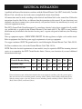
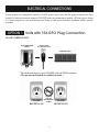
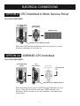
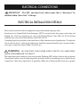
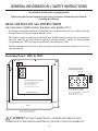
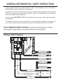
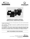
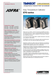
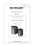
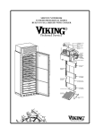
ADVANTAGE
SPA CONTROLS
DIGITAL SPA PACK OWNER’S MANUAL
TO ENSURE THAT THE SYSTEM IS INSTALLED PROPERLY,
PROVIDE YOUR ELECTRICIAN WITH THESE INSTRUCTIONS
To prevent potential injury and to avoid unnecessary service calls, read this manual
carefully and completely.
CAUTION – We highly recommend a qualified professional install and
service this product.
WARNING – This manual contains important safety information that must
be furnished to the end user of this product. FAILURE TO READ AND
FOLLOW ALL INSTRUCTIONS COULD RESULT IN SERIOUS INJURY.
SAVE THIS INSTRUCTION MANUAL
624 South B Street • Tustin, CA 92780
Toll Free: 800.636.8866 • Tel: 714.505.1166 • Fax: 714.505.1160
advantageman.com
IT IS EXTREMELY IMPORTANT
THAT YOU READ AND UNDERSTAND
THE INSTALLATION INSTRUCTIONS
BEFORE PROCEEDING. This will make
the installation easier, quicker and most
important safer.
If you have any technical questions
please contact us:
Advantage Manufacturing
1-800-636-8866
[email protected]
www.advantageman.com
2
SAFETY PRECAUTIONS
• These devices use high voltage and high current.
• ELECTROCUTION is possible if care is not taken.
• Disable the power supply (at the circuit breaker) when connecting
or removing any wires to the terminal block and/or when plugging
or unplugging any outboard components. This includes, but is not
limited to pumps, blowers, ozone generators, stereo systems,
topside controls, TV’s, lights etc.
• Use a volt meter to verify that all power is disabled.
• Do not apply power to test or check any components, until all
plumbing and electrical connections are made, the spa is
completely filled, and the control box cover is secure. Powering up
the spa will be the very last step.
• Do not stand in water or wet concrete when working on the spa
equipment.
• It is extremely important that the ground connection is intact. This
allows the GFCI circuitry to work properly.
• This control system must be hardwired to the electrical supply with
a minimum #8 gauge wire.
• The only exception to this is a spa that is designed to operate on a
120 volt circuit.
• 120v powered spas must use a GFCI protected power cord.
• Do not use extension cords of any type.
• Contact your local electrical supplier if your current wiring is
improper.
3
ELECTRICAL INSTALLATION
A qualified and licensed electrician in accordance with the National Electric Code (NEC) Article 680, Canadian
Electric Code, and with any local codes must accomplish the electrical installation.
All connections must be made according to the electrical installation label on the control box. Follow the
instructions from the label if they are different than the instructions in this manual. If your electrician is not
absolutely sure how to connect your system correctly, call your local dealer. Any mistake may be costly and
void your equipment warranty.
The GFCI (Ground Fault Circuit Interrupter) Is a mandatory electrical safety device required for all portable
spas and hot tubs as specified in the National Electrical Code Article 680-42. The GFCI in your particular
installation may be installed at the electrical service panel, a separate sub-panel or built into your Advantage
System.
Your spa equipment requires a DEDICATED CIRCUIT. No other appliances or lights can be on this circuit.
Refer to equipment data label for power supply requirements of your spa equipment.
Use copper conductors ONLY. The ground must be sized following the National Electric Code, Table 250-95.
For Power conductor size, refer to the National Electric Code Table 310-16.
NOTE: Due to the electrical requirements of some models, it may be required to SPLIT the incoming electrical
service to accommodate the GFCI Circuit Breaker limits. Contact your electrician if you need additional
information on this topic.
Circuit & Breaker Rating
15A
20A
30A
40A
50A
60A
70A
80A
Maximum Amps
12A
16A
24A
32A
40A
48A
56A
64A
14
12
10
8
6
4
4
4
Minimum Wire Size
Universal Systems require a Neutral wire therefore the service required is as follows: 120-volt systems require a
three-wire electrical service including ground, consisting of Line 1 (Black), Neutral (White) and Ground (Green).
240-volt systems require a four wire electrical service including ground, consisting of Line 1 (Black), Line 2
(Red), Neutral (White) and Ground (Green).
4
ELECTRICAL CONNECTIONS
If your system was configured to include a 120VAC power cord, ensure that the proper receptacle has been
installed (a dedicated circuit is required). DO NOT under any circumstances modify a 20 Amp plug to fit into
a 15 Amp receptacle or use an extension cord. Doing so will create hazardous conditions and/or void the
warranty.
OPTION 1 Units with 15A GFCI Plug Connection
20 AMp CORDEND GFCI
MAIN BREAKER
pANEL
DEDICATED
15A/120V OUTLET
pORTABLE SpA
This illustration depicts a typical 20 AMP, cord-end GFCI installation.
(The spa must be installed on a dedicated circuit.)
15 AMp
RECEpTACLE
DO NOT
USE AN
EXTENSION
CORD
5
20 AMp
RECEpTACLE
ELECTRICAL CONNECTIONS
OPTION 2 GFCI Installed in Main Service Panel
20-60AMp HARDWIRED
MAIN BREAKER
pANEL
INLINE SpA
DISCONNECT
pORTABLE SpA
REFER TO GFCI WIRING DETAIL
Power from GFCI breaker installed into main service panel to a service
disconnect within line-of-site ot the spa.
OPTION 2a SUBPANEL GFCI Installed
20-60AMp HARDWIRED
MAIN BREAKER
pANEL
GFCI
DISCONNECT
INLINE SpA
DISCONNECT
TO pORTABLE
SpA
REFER TO GFCI WIRING DETAIL
Power from main service panel to a GFCI subpanel within line-of-site of
the spa. (Note: Most local codes will allow a GFCI subpanel to be a
disconnect. If this is not the case in your installation, a disconnect must
be provided.)
6
ELECTRICAL CONNECTIONS
IMpORTANT – The NEC and most local codes require that a “disconnect” be
installed within “line-of-site” of the spa.
ELECTRICAL INSTALLATION DETAILS
Refer to the System Data Label for equipment voltage and maximum amperage draws.
Install proper size Ground Fault Circuit Interrupter (GFCI) or circuit breaker, then proper sized wiring and
bonding wire. For Power conductor size, refer to the National Electric Code Table 310-16. For Ground
conductor size, refer to the National Electric Code Table 250-122.
A bonding lug has been provided on the control box to allow connection to local ground points. To reduce the
risk of electrical shock, a solid copper bonding wire should be connected from this lug to any metal ladders,
water pipes or other metal object within 5 feet of the spa.
WARNING – BE SURE THAT YOUR POWER SUPPLY CIRCUIT CAN ADEQUATELY
HANDLE THE AMPERAGE YOU SELECT.
The control input power wiring may have been provided. Following NEC and local codes in effect at the time
of installation, connect (refer to wiring diagram located on the inside of control hinged cover) the Black wire
to input Line 1, Blue wire to input Line 2 (if applicable), White wire to Neutral and the Green wire to ground.
7
PRODUCT REGISTRATION
(Retain For Your Records)
DATE OF INSTALLATION
ADVANTAGE
POOL PUMPS
__________________________________________
INITIAL PRESSURE GAUGE READING (CLEAN FILTER) ________________
PUMP MODEL _____________________ HORSEPOWER ________________
FILTER MODEL ____________________________________________________
IMPORTANT SAFETY INSTRUCTIONS
When installing and using this electrical equipment, basic safety precautions should always be
followed, including the following.
READ AND FOLLOW ALL INSTRUCTIONS.
DANGER – To reduce the risk of injury, do not permit children to use this product unless they are
closely supervised by an adult at all times.
WARNING – RISK OF CHILDREN DROWNING. Extreme caution must be exercised to
prevent unauthorized access by children. To avoid accidents, ensure that children cannot use a spa or hot tub
unless they are supervised at all time.
DANGER – To reduce the risk of injury to persons, do not remove suction fittings.
INSTALLATION – Provide drainage ports wherever necessary.
HYpERTHERMIA – Prolonged immersion in water that is warmer than normal body temperature
can result in a dangerous condition known as HYpERTHERMIA. The causes, symptom, and effects of
hyperthermia may be described as follows - hyperthermia occurs when the internal temperature of the body
reaches a level several degrees above normal body temperature of 98.6°F. The symptoms of Hyperthermia
include dizziness, fainting, drowsiness, lethargy, and increase in the internal temperature of the body. The
effects of Hyperthermia include (1) unawareness of impending hazard, (2) failure to perceive heat, (3) failure
to recognize the need to exit the spa, (4) physical inability to exit the spa, (5) fetal damage in pregnant women
and (6) unconsciousness resulting in a danger of drowning. WARNING – The use of alcohol, drugs, or
medication can greatly increase the risk of fatal Hyperthermia in hot tubs and spas.
8
PRODUCT OVERVIEW
Digital Spa pack is an electronically controlled equipment designed to control spa (Hot tub) equipment.
Pack Consists of (But Not Limited To) electric heater, top side controller and control pack for controlling
pumps, air blower, lights and other auxiliary equipment used in the operation of spas.
Primary function of pack is controlling water temperature.
Heater’s electrical circuit is controlled by a pressure switch located within the heater assembly. Heater
will operate only when the pressure switch is in the closed position indicating that water is flowing over
the heating element.
Also, heater’s electrical circuit is controlled by low speed of primary pump. Heater will operate only
when the two conditions are present.
Digital spa pack has a high temperature safety limit and a freeze protect safety limit built in the pack’s
software logic.
When water temperature reaches 118°F the system will shut down.
The system can be manually reset only when water reaches temperature of 112°F. When water temperature
reaches 45°F the system will automatically start primary pump and heater until water temperature will
reach 52°F.
FREEZE pROTECT OVERRIDE (FpO)
The function is intended to be used on power-up or start-up after a fresh fill and will suspend the freeze
protect feature for 6 hours in order to allow the installer to check for normal operation if the is filled
with water at a temperature of less than the set freeze protect level.
By pressing pUMp 1 and LIGHT keys simultaneously for 10 seconds the Freeze Protect feature will
be suspended for 6 hours.
To manually go back to freeze protect mode just power down the system and re-boot.
GENERAL INFORMATION
Electronic Control
Digital program R96
part Number #D5500
Setup............................... LC ..................... HC
Control ............................ 110 .................... 220
Jet 1 Red ......................... 110 .................... 220
Blower Blue.................... 110 .................... 220
Ozone Pink .................... 110 .................... 220
Jet 2 Orange .................... 110 .................... 220
Heater ............................. 110 .................... 1.5Kw
Titanium ......................... Yes .................... No
Heater ............................. 220 .................... 5.5Kw
9
GENERAL INFORMATION / SAFETY INSTRUCTIONS
Unit should be installed only in upright position.
When using this electrical equipment basic safety precautions should always be followed,
including the following.
READ AND FOLLOW ALL INSTRUCTIONS
USE ONLY SOLD COppER CONDUCTOR NIM. 6 AWG RATED AT 75°C.
All electrical connections should be accomplished by a qualified electrician in accordance with the
National Electrical Code or Canadian Electrical Code.
The electrical supply for permanently connected units should be dedicated only to the spa Control box
(not to be shared by any other electrical appliance) and must include a suitable rated Ground Fault
Circuit Interrupter (GFCI) in compliance with the National Electrical Code.
The Disconnecting means must be readily accessible to the tub occupant but installed at least 5 feet
away from the tub.
Incoming power 110V & 220V
Ground
New
New
L2
L2
L1
L1
To Change Control to 110 Volt:
Incoming Power Wire #12 AWG
White Jumper
Ground
For 220 Volt 60Hz 4 Wire 30 or 50 Amp:
Step 1 Connect White to Neutral
Step 2 Connect Black to L1
Step 3 Connect Red to L2
Step 4 Connect Green to Ground
L1
L2
New
L1
L2
New
For 110 Volt 60Hz 3 Wire 20 Amp
Step 1 Connect White to Neutral
Step 2 Connect White Jumper from Neutral to L2
Step 3 Connect BIack L1
Step 4 Connect Green to Ground
MINI MAX BOARD
BASE
Wire Size For 220 Volt #6 to #8 AWG
Wire Size For 110 Volt #12 AWG
CAUTION!! MUST BE CONNECTED BY A LICENSED ELECTRICIAN. NONCOMPLIANCE TO THE NATIONAL ELECTRICAL CODE WILL VOID YOUR WARRANTY.
10
GENERAL INFORMATION / SAFETY INSTRUCTIONS
A green colored terminal of a terminal marked G, GR, Ground, Grounding, Or the “G” Symbol is
located inside the supply terminal box or compartment.
To reduce the risk of electric shock, this terminal must be connected to the grounding by Means provided
in the electric supply service panel with a continuous copper wire equivalent in size to the circuit
conductors supplied with this equipment.
A bus bar marked “BONDING LUGS” is provided on the external surface of the supply terminal box
or compartment.
To reduce the risk of electric shock, connect the local common bonding grid in the area of the hot tub
or spa to these terminals with an insulated or hare copper conductor not smaller than No.6 AWG.
SAVE THESE INSTRUCTIONS! POTENTIAL RISKS OF PERSONAL INJURY
OR HEALTH HAZARDS MAY BE ASSOCIATED WITH USE OF EQUIPMENT!
Wiring a G.F.C.I Breaker
O
N
60
60
O
F
F
TEST
LOAD
POWER
LOAD
LOAD
NEUTRAL POWER
LINE NEUTRAL
LINE 2 – INPUT
LINE 1 – INPUT
GROUND – INPUT
GROUND TO SPA
LOAD 2
120 volts
LOAD NEUTRAL
240 volts
120 volts
LOAD 1
11
START UP AND OPERATION
Power up system and “PUR” is displayed on topside panel for 30 seconds while in purge mode. During purge
cycle all devices connected to controller come on and the self diagnosis program. Checks for proper function
of all components.
GENERAL SETUp
Press HEAT key and LIGHT key simultaneously and hold until display shows LC (low current - 110V AC)
or HC (High Current - 220V AC). Once the display shows any of these two messages you are in a closed
loop for your personal preferences controller setup.
CURRENT VOLTAGE SELECTION (while in General Setup Mode)
Press JET ONE key (far left key on topside) to toggle between LC and HC.
pUMp #1 SETUp (while in General Setup Mode)
Press HEAT key to move to next level (Pump #l setup) p11, p12 or p10 will show on Display. Select your
preference according to your Pump#l requirements:
p11 - Pump #1 Single Speed (each pressing of Pump 1 key will turn pump on or off)
p12 - Pump #1 Two Speed (each pressing of Pump 1 key will toggle between pump #1 low speed and
high speed)
p10 - Pump # l Two speed with pump OFF selection (first activation of pump 1 key will tum pump on
low speed, second activation of pump 1 key will tum high speed on and third activation of pump
1 key will tum pump off. Cycle will repeat at the activation of pump 1 key on top side). Unit will
run for only 30 minutes at a time on this setting.
(Pressing HEAT key will move system program to next level of setup)
pURGE CYCLE INTERVAL
Press HEAT to move to next level (Purge Interval Setup) P6 or P12 will show on topside display Select as
follows:
p6 - Purge system every 6 hours.
p12 - Purge system every 12 hours.
Note: Purge Function is permanently programmed into controller’s memory and is necessary in order
to insure proper operation of system. During the purge cycle all controller functions are tested for 30
seconds.
FILTRATION CYCLE DURATION
Press HEAT and BLOWER key simultaneously and hold to adjust filter cycle (automated operation necessary
to keep spa water clean). Each number on display represents the number of hours the filter cycle will operate
on 12 hours period (12 hours max).
12
START UP AND OPERATION
HOT TUB OpERATION
Press JET ONE key to activate Pump one (Primary pump that controls the heater also). Pump will operate for
30 minutes and will shut off automatically after 30 minutes unless key is activated again. Each time Jet One
key is activated the timer resets.
Press HEAT key to adjust temperature. Press once and hold and will raise temperature. Press a second time
and hold will lower temperature to a minimum of 70°F (21°C). Red LED at the topside control will flash as
long as heater is on.
Press BLOWER (bubbles) Key to activate Air Blower on/off.
Press JET 2 key to activate secondary pump.
ERROR CODES
If tub water temperature reaches 112°F the LED display will flush “OH” and shut the system down until the
water temperature drops bellow 112°F.
There is a third level of protection via a high limit relay that will trip at 118°F if this point is achieved the
topside control will display “HL” (HIGH LIMIT) and the water temperature must cool to less than 112°F for
the system to reset. This is an unusual situation and we recommend to contact a certified spa technician to
check for possible problems.
CARE INSTRUCTIONS
READ CAREFULLY – pROTECT YOUR WARRANTY
SpA WATER CARE
Changing water regularly and maintaining correct chemical balance will keep your spa safe and sanitary, and
will protect your spa pack and its warranty coverage.
CHLORINE OR BROMINE – Recommended level 3 to 5 PPM TEST before use (every 2 hours
during heavy use)
pH – Recommended level 7.4 to 7.6 High readings reduce sanitizer efficency. Low readings are
corrosive.
TOTAL ALKALINITY – 80 TO 100 PPM Test weekly during regular use. Low readings are corrosive
and cause rapid PH changes when chemicals are added.
CALCIUM HARDNESS – 150 TO 300 PPM Test whenever spa is refilled. Low levels (soft water)
can be very corrosive.
Remember, addition of any chemicals can change levels of chlorine pH and total alkalinity.
WHEN IN DOUBT, CHANGE THE WATER
13
DIGITAL SPA PACK – DIGITAL SIDE VIEW
POWER IN
Top-Side Control
Thermostat
Thermisters
Jets 2 Cord is
White Neutral
Black Hi Speed
Green Ground
2nd PUMP REC.
OZONE REC.
BLOWER REC.
PUMP REC.
Jets 1 Cord is
White Neutral
Black Hi Speed
Red Low Speed
Green Ground
14
L2
15
RELAY
C 40 PMSF
HDI-012DNO 40A/240VAC
NC:30A/240VAC
To J31
G
J15
J14
J13
J33
From Relay
To J12
To J9
Class 2 Transformer
Model No: DA-36-127b
Input: 120VAC 60Hz 45VA
Output: 12VAC 3.0A 36VA
To J7
J16
J24
Heater
ZETTLER
A22150-1A-12DE
40A 250VAC
1HP 125VAC
ZETTLER
A22150-1A-12DE
40A 250VAC
1HP 125VAC
J32
To J6
fuse
FROM
2nd
PUMP
REC.
J24
To J31
J11
J10
J9
Transf
L1
L2
J35
J4 J5 J6 J7
J33 J34 J31 J30
Neutral
light 12vac
aux2 aux1
Transf
J12
Neutral
SETING ON TOP-SIDE
1-PUR
2-LC -HC
3-104
4-P12
5-P6
Power in
BLACK L1
RED
WHITE Neutral
GROUND
J17
ZETTLER
A22150-1A-12DE
40A 250VAC
1HP 125VAC
ZETTLER
A22150-1A-12DE
40A 250VAC
1HP 125VAC
J18
J19
Light Harness
To Light J5
To Light J4
Hi Limit
J9
From Ozone Rec.
Thermisters
T. Stat
To Pressure Sw
ZETTLER
A22150-1A-12DE Pump 1
High
40A 250VAC
J20
1HP 125VAC
ZETTLER
A22150-1A-12DE Pump 1
Low
40A 250VAC
J21
1HP 125VAC
To Pressure Sw
Pressure Sw
J33
J1
J2
ZETTLER
Pump 2
A22150-1A-12DE
J22
40A 250VAC
1HP 125VAC
R96
TOP SIDE
J23
J9
To Heater
To J20
To J21
To J10
To J21
1st Pump 2 speed
Rec.
To J10
Blower Rec.
To J22
To Contractor
To Heater
J15
Ozone Rec.
Heater
To J13
Aux
2nd Pump or Aux
Rec.
To Relay
Light Blower Jet 2
104 Splash Spas
For 220 Volt Pump White to J32
For 220 Volt 2nd Pump White to J14
For 220 Volt Blower White To J13
For 220 Volt Ozone White To J14
J16
Contractor
Contractor
J25
Jet 1
Invert
DIGITAL SPA PACK – PART #D5500
TROUBLESHOOTING
DISpLAY FLASHES “FLO”
This indicates flow water problem or defective
pressure switch.
Check filter.
Check service valves are open.
Check for any obstruction of water flow.
NO DISpLAY AT TOpSIDE
Check that connection to main board is clean and
sound at J8.
Test a new topside control.
Check for 120V primary power going into the
transformer and for 12V secondary power out of
the transformer to J6 & J7 on the board before
replacing the transformer.
Replace board if there is 12V to J6 & J7.
DISpLAY FLASHES “FLC”
This indicates the pressure switch is stuck in the
closed position Replace pressure switch.
DISpLAY FLASHES “TH 1/39” OR “__”
Check that temperature sensing probe connection
to main board is clean and sound at location J2.
Try new temperature sensing probe.
ERRATIC OpERATION AT TOpSIDE pANEL
Check for proper connection at J8.
Shut off system and restart.
Check cable connection at the topside panel
control housing.
Try new topside control.
Replace main PCB board.
DISpLAY FLASHES “TH 2/ CURRENT
TEMpERATURE” OR “__”
Check that the temperature sensing probe
connected to the main Board is clean and sound
at location J1.
Try new temperature sensing probe.
NO HEAT
Make sure water temperature is bellow 112°F.
Check for flashing Led at topside control. This
indicates the system is demanding for heat. Air
pocket present in pressure switch. Remove air
packet in pressure switch by slowly loosening
heater pipe nut at the end further from pump.
Make sure you don’t open too much the nut. Only
small amount of water should escape and then
retighten nut. Repeat this operation 4-6 times in
order to release all air trapped inside pressure
switch.
Check pressure switch. Replace if defective.
DISpLAY FLASHES “TH 2/39” OR “__” ON
SYSTEM STARTUp
This indicates that both thermisters are detecting
tub water temperature of less than 39°F.
(4°C) or they are both disconnected (OPEN).
Pump(s) and blower will run in this condition.
DISpLAY
FLASHES
“OH”
OR
TEMpERATURE VALUE IS FLASHING
This indicates that the spa water temp is over
112°F the system should be shut down is this stat
and will re-start automatically when the water
cools below 112°F.
OVERHEAT
If water temperature is too high and the high limit
has tripped the water temperature must be allowed
to drop bellow 112°F.
Water circulation is too low allowing the heater
body to overheat. Check for water flow restrictions
including water pump function.
DISpLAY
FLASHES
“HL”
OR
TEMpERATURE VALUE IS FLASHING
This indicates that either the heater or the spa has
reached 118°F or higher. The system will not
restart automatically. To re-start the system the
water temperature must be below 112°F and the
heater key at the topside control must be pressed.
16
1 YEAR LIMITED WARRANTY
CLAIMS: All claims must be made within ten (10) calendar days after
receipt of the merchandise. If any shipment is Here received in a
damaged condition, your claim must be filed with the delivering carrier
and noted on the freight bill before you accept the merchandise.
BREACH OF THIS AGREEMENT OR WHETHER ANY REMEDY
PROVIDED.
HEREIN FAILS OF ITS ESSENTIAL PURPOSE. APP’S LIABILITY
AND BUYER’S SOLE REMEDY, WHETHER IN CONTRACT,
UNDER WARRANTY, IN TORT (INCLUDING NEGLIGENCE,) IN
STRICT LIABILITY OR OTHERWISE, SHALL NOT EXCEED THE
RETURN OF THE AMOUNT OF THE PURCHASE PRICE PAID BY
BUYER AND SHIPMENT COSTS.
RETURNS: All returns are subject to our written approval and must be
accompanied by a “Return Goods Authorization” number obtained from
APP prior to shipment. Unauthorized returns will not be accepted.
Freight must be prepaid. Material returned for credit, if in original
condition and resalable, is subject to a 20% handling charge.
INDEMNIFICATION: Buyer will defend and indemnify APP and its
directors, employees, agents, customers, end users, successors and
assigns from and against all actual and alleged claims, liabilities, suits,
damages, losses and expenses (including attorney’s fees and legal costs)
arising from, or caused in whole or in part, by buyers breach of any
provision, term or condition of purchase.
TAXES: Any Federal or State Excise or Sales Tax for which APP may
be liable on any sale will be charged to and paid by the buyer. Buyer is
responsible for furnishing a resale certificate.
PRICES: Prices and Products are subject to change without notice.
LIMITED WARRANTY: To Buyer, as original purchaser of the Goods,
APP warrants its products free from defects
BINDING EFFECT: All sales transactions are binding on APP and the
buyer and their respective directors, officers, employees, agents,
subcontractors, successors and permitted assigns.
in materials and workmanship for a period of one year from the date of
purchase. Parts which fail or become defective during the warranty
period, except as a result of freezing, negligence, improper installation,
use or care, shall be repaired or replaced, at our option, within ninety
(90) calendar days of the receipt of the defective product, barring
unforeseen delays. To obtain warranty, replacements or repair, defective
components or parts should be returned, transportation paid, to the place
of purchase. No returns may be made directly to the factory without the
express written authorization of APP. Pump housing/strainers which
become defective during the warranty period, except as a result of
freezing, negligence, improper installation, use or care, or as the result
of use in association with an automatic valving system, shall be repaired
or replaced, at APP’s option, without charge. All other conditions and
terms of the standard warranty apply. APP shall not be responsible for
cartage, removal and/or re installation labor or any other cost incurred
in obtaining warranty replacements. The foregoing warranty does not
apply to components manufactured by others. For such products, the
warranty established by the respective manufacturers will apply.
GOVERNING LAW: All transactions will be interpreted and enforced
under the laws of the State of California (including without limitation
the Uniform Commercial Code as adopted by the California), without
recourse to the conflict of laws provision thereof. In no event will the
provisions of the UN Convention of the International Sale of Goods
apply to any purchases. APP and buyer agree that any action or
proceeding arising out of or in connection with any sale of product or
service, will be brought exclusively to a court of competent jurisdiction
in the County of Orange, State of California.
THE LIMIT OF LIABILITY FOR ANY CLAIMS SHALL NOT
EXCEED THE AMOUNT PAID OR PREPAID ON ACCOUNT BY
BUYER FOR THE GOODS GIVING RISE TO SUCH CLAIMS.
BUYER SHALL BE DEEMED TO ASSUME ALL LIABILITY FOR
ANY AND ALL DAMAGES ARISING FROM OR IN
CONNECTION WITH THE USE OR MISUSE OF THE GOODS BY
BUYER, ITS EMPLOYEES, CUSTOMERS AND OTHERS.
SELLER SHALL NOT BE LIABLE FOR AND BUYER AGREES
TO INDEMNIFY, DEFEND AND HOLD SELLER HARMLESS
FROM ANY CLAIMS BASED ON SELLER’S COMPLIANCE
WITH
BUYER’S
DESIGNS,
SPECIFICATIONS
OR
INSTRUCTIONS, OR MODIFICATION OF ANY GOODS BY
PARTIES OTHER THAN SELLER, OR USE IN COMBINATION
WITH OTHER PRODUCTS. EACH PARTY RECOGNIZES AND
AGREES THAT THE WARRANTY DISCLAIMERS AND
LIABILITY AND REMEDY LIMITATIONS HEREIN ARE
MATERIAL, BARGAINED FOR BASES OF ANY ORDER OR
CONTRACT AND THAT THEY HAVE BEEN TAKEN INTO
ACCOUNT AND REFLECTED IN DETERMINING THE
CONSIDERATION TO BE GIVEN BY EACH PARTY UNDER ANY
ORDER OR CONTRACT AND IN THE DECISION BY EACH
PARTY TO ENTER INTO SUCH ORDER OR CONTRACT.
LIMITATION ON IMPLIED WARRANTIES: Implied warranties,
including any warranty or merchantability imposed on the sale of the
goods under state law, are limited to one year duration for the goods or
any parts.
LIMITATIONS OF LIABILITY: THE ESSENTIAL PURPOSE OF
THIS PROVISION IS TO LIMIT APP’S LIABILITY HEREUNDER.
EXCEPT FOR BODILY INJURY OR DEATH OF A PERSON,
UNDER NO CIRCUMSTANCES WILL APP, ITS EMPLOYEES,
OFFICERS OR DIRECTORS, AGENTS, SUCCESSORS OR
ASSIGNS, BE LIABLE TO ANYONE UNDER ANY PRODUCT
ORDER, SCHEDULE OR TERMS AND CONDITIONS HEREIN,
UNDER ANY CONTRACT, STRICT LIABILITY, TORT
(INCLUDING NEGLIGENCE) OR OTHER LEGAL OR
EQUITABLE THEORY, WHETHER OR NOT FORESEEABLE OR
FORESEEN, FOR: (1) BUSINESS INTERRUPTION COSTS, COST
OF REWORK, RETESTING, PROCUREMENT OF SUBSTITUTE
GOODS, REMOVAL AND RE INSTALLATION OF GOODS; OR (2)
ANY SPECIAL, INCIDENTAL, EXEMPLARY, INDIRECT OR
CONSEQUENTIAL DAMAGES, INCLUDING WITHOUT
LIMITATION LOST PROFITS, LITIGATION COSTS, LOSS OF
EQUIPMENT, PRODUCTION OR PROFIT, GOODWILL, LOSS OF
REVENUE, OR LOSS OF UNITS; COST OF RENTING
REPLACEMENTS, AND OTHER ADDITIONAL EXPENSES,
EVEN IF THE AP HAS BEEN ADVISED OF THE POSSIBILITY OF
SUCH DAMAGES, THERE IS A TOTAL AND FUND A MENTAL
Copyright Notices: Polaris® is a registered trademark of Zodiac Pool Care, Inc.,
Letro® is a registered trademark of Letro Products, Sta-Rite® is a registered trademark
of Sta-rite Industries, Hayward® is a registered trademark of Hayward Manufacturing
Co., Inc., WhisperFlo® is a registered trademark of Pentair Pool and Spa, Inc., Noryl
is a registered trademark of GE Plastics, Northstar™ is a trademark of Hayward
Manufacturing Co., Inc., Cal Spas® is a registered trademark of California Acrylic
Industries, Inc., Aquaflo® is the registered trademark of LSP Products Group, Inc.,
Vico® is a registered trademark of Vico Industries, Waterway® is a registered
trademark of Waterway Plastics, Advantage Manufacturing™ is trademark of
Advantage Manufacturing, Federal Copyright – Advantage Manufacturing ©2007.
17