1
DUAL SATELLITE ROUTER
UHP-8000
GENERAL DESCRIPTION AND INSTALLATION GUIDE
DOCUMENT RELEASE 3.2
[UHP.8R32.EN]
JANUARY 2015
UHP-8000 DUAL SATELLITE ROUTER
GENERAL DESCRIPTION AND INSTALLATION GUIDE, v3.2
CONTENT
Acronyms and Abbreviations ..........................................................................................................4
Introduction .....................................................................................................................................6
Required level of qualification ..................................................................................................................6
Document version and applicability..........................................................................................................6
Copyright ...................................................................................................................................................6
1.
General description ..............................................................................................................7
1.1
System overview .......................................................................................................................7
1.1.1
1.2
Purpose .....................................................................................................................................7
Router composition ..................................................................................................................7
1.3
Measurement equipment, tools and accessories ....................................................................7
1.4
Labeling and sealing..................................................................................................................8
1.5
Packaging and content..............................................................................................................8
1.6
Description and principles of operation ...................................................................................8
1.6.1
1.6.2
1.6.3
1.6.4
1.6.5
1.6.6
1.6.7
1.6.8
1.6.9
1.6.10
1.6.11
1.6.12
2.
Operations ..........................................................................................................................13
2.1
Operational limits ...................................................................................................................13
2.2
Preparation for use .................................................................................................................13
2.2.1
2.2.2
2.2.3
2.2.4
2.2.5
2.2.6
2.2.7
2.2.8
3.
Overview ...................................................................................................................................8
Power connector (Power input A/B) ........................................................................................9
USB CONSOLE (USB A/B) ..........................................................................................................9
IF input (RX) ..............................................................................................................................9
LAN interface connector (LAN A/B) ........................................................................................10
Modulator output (TX)............................................................................................................10
“ERROR” Indicator ..................................................................................................................11
“STATUS” Indicator .................................................................................................................11
“LOCK” Indicator .....................................................................................................................11
“TDMA” Indicator ..............................................................................................................11
“SCPC” Indicator ................................................................................................................12
“TX” Indicator ....................................................................................................................12
Unpacking ...............................................................................................................................13
Installation ..............................................................................................................................13
Connecting to external devices ..............................................................................................13
Powering on ............................................................................................................................14
Local access to router via HTTP interface ...............................................................................15
Local access via USB................................................................................................................15
Remote Telnet access .............................................................................................................15
Command Interface ................................................................................................................15
Operations ..........................................................................................................................16
© ROMANTIS 2015
2
www.uhp.net
UHP-8000 DUAL SATELLITE ROUTER
GENERAL DESCRIPTION AND INSTALLATION GUIDE, v3.2
3.1
Software updates....................................................................................................................16
3.2
Powering off ...........................................................................................................................16
3.3
Safety instructions for operations ..........................................................................................16
3.4
Actions in case of fire..............................................................................................................16
4.
Troubleshooting .................................................................................................................17
4.1
Replacement of modules ........................................................................................................18
4.1.1
4.1.2
5.
Common recommendations ...................................................................................................18
Safety instructions ..................................................................................................................18
STORAGE, TRANSPORTATION AND DISPOSAL....................................................................19
FIGURES
Figure 1 Structure of UHP Manuals...............................................................................................................6
Figure 2: Standard labeling of satellite router ..............................................................................................7
Figure 3: UHP-8000 satellite router – rear view ...........................................................................................8
Figure 4 Standard internal configuration of UHP-8000 router .....................................................................8
Figure 5 Internal configuration of UHP-8000 in Hub (HBIC) mode ...............................................................9
Figure 6 Internal configuration of UHP-8000 in dual Inroute (ICIC) mode .................................................10
Figure 7 Satellite Router UHP-8000 series front view.................................................................................11
Figure 8 Example of router’s connection in a basic mode of operation. ....................................................14
Figure 9 Example of router's connection in Hub mode (with 3 Inroutes)...................................................14
TABLES
Table 1 Operational limits ...........................................................................................................................13
Table 2 Troubleshooting guide....................................................................................................................17
© ROMANTIS 2015
3
www.uhp.net
UHP-8000 DUAL SATELLITE ROUTER
GENERAL DESCRIPTION AND INSTALLATION GUIDE, v3.2
ACRONYMS AND ABBREVIATIONS
16APSK
32APSK
8PSK
AGC
BCH
BUC
C/N
CRTP
DAMA
DSCP
DVB
Eb/No
EIRP
ETSI
FEC
Frame
Hard priority
HTTP
HUB
Hubless
HW
ICMP
IESS
IFL
IGMP
Inroute
IP
LDPC
LNB
Local oscillator
Long frames
Master
MCPC
Mesh
MF-TDMA
MODCOD
NMS
Node Station
ODU
Outroute
QPSK
RF level
RSV
16 Amplitude and Phase-shift keying or Asymmetric Phase-shift keying, (APSK), is a digital modulation scheme that
conveys data by changing or modulating both the amplitude and the phase of a reference signal (the carrier wave).
32 Amplitude and Phase-shift keying or Asymmetric Phase-shift keying, (APSK), is a digital modulation scheme that
conveys data by changing, or modulating, both the amplitude and the phase of a reference signal (the carrier wave).
Phase-shift keying (PSK) is a digital modulation scheme that conveys data by changing or modulating the phase of a
reference signal (the carrier wave).
Automatic Gain Control
BCH code is a multilevel cyclic variable-length digital error-correcting code used for correcting multiple random error
patterns. BCH codes may also be used with multilevel phase-shift keying whenever the number of levels is a prime
number or a power of a prime number.
Block Up-Converter (BUC) is used in the transmission (uplink) of satellite signals. It converts a band (or "block") of
frequencies from a lower frequency to a higher frequency.
Carrier-to-noise ratio, often written as CNR or C/N, is the signal-to-noise ratio (SNR) of a modulated signal.
Compressing IP/UDP/RTP Headers for Low-Speed Serial Links
Demand Assigned Multiple Access. Channel establishment on demand.
Differentiated Services Code Point (DSCP) is a 6-bit field in the header of IP packets for packet classification purposes.
DSCP replaces the outdated IP precedence, a 3-bit field in the Type of Service byte of the IP header originally used to
classify and prioritize types of traffic
Digital Video Broadcasting (DVB) is a suite of internationally accepted open standards for digital television.
Eb/N0 (the energy per bit to noise power spectral density ratio) is an important parameter in digital communication or
data transmission. It is a normalized signal-to-noise ratio (SNR) measure, also known as the "SNR per bit". It is especially
useful when comparing the bit error rate (BER) performance of different digital modulation schemes without taking
bandwidth into account.
Effective Isotropically Radiated Power
The European Telecommunications Standards Institute (ETSI) is an independent, non-profit, standardization
organization in the telecommunications industry (equipment makers and network operators) in Europe, with worldwide
projection.
In telecommunication and information theory, forward error correction (FEC) is a system of error control for data
transmission, whereby the sender adds redundant data to its messages, also known as an error-correction code.
TDMA service packet describing which station should transmit in which time slot . Generated ~10 times per second.
Method of transmission queues handling when packets from lower priority queue are not transmitted until all packets
from higher priority queue are transmitted.
Hypertext Transfer Protocol (HTTP) is an application-level protocol for distributed, collaborative, hypermedia
information systems.
Central Station of satellite network that is managing all the terminals and resources
Special mode of operation when all stations are transmitting to one TDMA carrier and all receiving this carrier.
Hardware
The Internet Control Message Protocol (ICMP) is used by networked devices to send error messages—indicating, for
instance, that a requested service is not available or that a host or router could not be reached.
Intelsat Earth Station Standards
Connection from the indoor equipment (modem/router) to the outdoor equipment at the antenna normally involves
two inter-facility (IFL) cables.
The Internet Group Management Protocol (IGMP) is a communications protocol used by hosts and adjacent routers on
IP networks to establish multicast group memberships.
Channel from stations to hub.
IP is the usual abbreviation for Internet Protocol.
Low-density parity-check (LDPC) code is a linear error correcting code, a method of transmitting a message over a noisy
transmission channel, and is constructed using a sparse bipartite graph.
Low-noise block converter is the receiving converter installed at satellite antenna.
Oscillator built into RF block converter ( BUC or LNB ). Value of LO is usually written on block enclosure or in datasheet.
DVB-S2 frames 64800 bits long (including FEC). Require slightly lower C/N than short frames.
Main station of Hubless network. Master allocates bandwidth and performs stations acquisition.
Multiple channels per carrier. All TDM carriers generated by UHP can be treated as MCPC. Even if they are called SCPC.
Capability of station allowing to receive other stations via TDMA link.
TDMA working on several RF channels simultaneously. All MF channels work as one aggregate TDMA channel.
Modulation and coding mode.
Network Management System
Terminal of satellite network which is able to receive information directly from other network terminals
Out-Door Unit
Forward TDM channel (MCPC) from HUB to stations.
Phase-shift keying (PSK) is a digital modulation scheme that conveys data by changing, or modulating, the phase of a
reference signal (the carrier wave).
Absolute RF level of entire signal (carrier + adjacent carriers) expressed in dBm.
Reed–Solomon error correction is an error-correcting code that works by oversampling a polynomial constructed from
the data.
© ROMANTIS 2015
4
www.uhp.net
UHP-8000 DUAL SATELLITE ROUTER
GENERAL DESCRIPTION AND INSTALLATION GUIDE, v3.2
SCPC
Short frames
SNMP
SNTP
SNR
SR
Star
SW
TDM
TDMA
Telnet
Terminal
TFTP
Timestamp
Time-slot
UDP
USB
VLAN
VoIP
VSAT
WFQ
X-modem
Single Channel Per Carrier
DVB-S2 frames 16200 bits long (including FEC). Advisable to use at lower symbol rates. Produce less delay than Long
frames.
Simple Network Management Protocol
Simple Network Time Protocol (SNTP) is a protocol and software implementation for synchronizing the clocks of
computer systems over packet-switched, variable-latency data networks.
Signal-to-noise ratio is an electrical engineering measurement defined as the ratio of a signal power to the noise power
corrupting the signal.
Symbol Rate
Type of network with one central station (hub) and several peripheral stations.
Software
Time Division Multiplexing
Time Division Multiple Access
Telecommunication Network (Telnet) is a network protocol used on the Internet or local area networks to provide a
bidirectional interactive communications facility. Typically, telnet provides access to a command-line interface on a
remote host via a virtual terminal connection.
Earth Stations (usually VSAT) operated under management of network HUB
Trivial File Transfer Protocol (TFTP) is a file transfer protocol, with the functionality of a very basic form of File Transfer
Protocol (FTP).
Time format used by UHP. Plus sign at the beginning (+HH:MM:SS or +NN d HH:MM:SS)denotes relative time from some
event or UHP start-up. If UHP has time synchronized to hub or SNTP absolute time can be displayed. Time zone affects
absolute time.
Time interval for station transmission.
The User Datagram Protocol (UDP) is the set of network protocols used for the Internet. With UDP, computer
applications can send messages, in this case referred to as datagram, to other hosts on an Internet Protocol (IP) network
without requiring prior communications to set up special transmission channels or data paths.
USB (Universal Serial Bus) is a specification to establish communication between devices and a host controller (usually
personal computers).
A virtual LAN, commonly known as a VLAN, is a group of hosts with a common set of requirements that communicate as
if they were attached to the same broadcast domain, regardless of their physical location.
Voice over Internet Protocol (VoIP) is a general term for a family of transmission technologies for delivery of voice
communications over IP networks such as the Internet or other packet-switched networks.
Very Small Aperture Terminal – satellite earth station with small-size antenna
Weighted fair queuing. Method of proportional division of bandwidth between transmission queues.
Simple file-transfer protocol
© ROMANTIS 2015
5
www.uhp.net
UHP-8000 DUAL SATELLITE ROUTER
GENERAL DESCRIPTION AND INSTALLATION GUIDE, v3.2
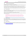
INTRODUCTION
This document presents a general description of the UHP-8000 series satellite routers and is intended for
familiarization with the system capabilities and specifications. This manual describes all the key modes of the
router operations.
Required level of qualification
This manual is intended for engineering personnel operating VSAT networks. Such specialists should have
adequate educational credentials in the field of electronics and sufficient experience and skills in data networks
administration and satellite systems.
Document version and applicability
UHP VSAT platform is based on the universal satellite router UHP, which is available in different fully-compatible
hardware modifications. UHP satellite router is a basic element of any network architecture and can be used in any
combinations and at any hierarchy level. Router functional capabilities and its operating modes are determined by
the installed software and its configuration.
This manual is applicable to all UHP-8000 series satellite routers with software release 3.2 or higher. When
ordering this document, please specify its ID: [UHP.8R32.EN].
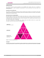
System Level
(Network engineering guide)
Network
Engineering
SCPC
Modem
Service Level
(User manual)
TDM/TDMA
Terminal
Hubless
TDMA
Station
UHP-8000
UHP-IFS
Hardware Level
(Installation guide and
specifications)
UHP-1000
UHP-200
NMS
Figure 1 Structure of UHP Manuals
Copyright
The content of this document is the intellectual property of Romantis Inc. (referred to below as Romantis). Copying
or quoting this description as a whole or of any part of it without a written permission from Romantis is prohibited.
© ROMANTIS 2015
6
www.uhp.net
UHP-8000 DUAL SATELLITE ROUTER
GENERAL DESCRIPTION AND INSTALLATION GUIDE, v3.2
1.
GENERAL DESCRIPTION
1.1
System overview
1.1.1
Purpose
UHP satellite routers are essentially a universal solution for geographically distributed VSAT-class satellite
communication networks. UHP routers can be used to organize simple point-to-point channels, “star”- and
“mesh”-topology networks with several hierarchy levels and bandwidth-on-demand capabilities.
UHP-8000 dual satellite router is an integrated chassis with two UHP-1000 routers and IF subsystem that can be
used as two independent routers or as elements of some complex system (e.g. Hub, redundant modules, etc.).
1.2
Router composition
UHP-8000 router consists of:
1.3
1.
Integrated UHP-1000 satellite router “A”;
2.
Integrated UHP-1000 satellite router “B”;
3.
IF subsystem with combiner and divider;
4.
Integrated power supplies (individual for each router);
5.
1U rack-mountable chassis
Measurement equipment, tools and accessories
Standard computer (notebook) is required to configure and monitor status of UHP-8000 satellite router. The
computer must be equipped with a LAN interface and USB, and also have the following software installed:
Internet browser (WEB browser)
Telnet Client
The Terminal (e.g.: Hyperterminal, included in the OS Windows) (optional)
The router can be accessed via LAN or USB ports. Standard USB AM/BM cable (not supplied) is required for
connection to USB “Console” port of the satellite router.
Connection of a computer to the router via LAN interface is implemented through the Ethernet switch or hub via a
standard network cable with RJ-45 connectors (not supplied).
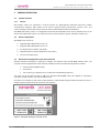
Figure 2: Standard labeling of satellite router
© ROMANTIS 2015
7
www.uhp.net
UHP-8000 DUAL SATELLITE ROUTER
GENERAL DESCRIPTION AND INSTALLATION GUIDE, v3.2
1.4
Labeling and sealing
The product is marked with the unique Serial Number on the bottom of the router’s case.
The warranty seals are located on the bottom of the product, at the junction of the two parts of the case.
Product’s warranty will automatically void if such labels have been removed, modified or damaged.
1.5
Packaging and content
Satellite router comes as an integrated chassis. It is recommended to keep original packaging throughout the
entire lifetime. Conservation, storage and transportation of the terminal must be in original packaging.
Standard package includes:
1.
UHP-8000 dual satellite router
2.
Power cables
1.6
Description and principles of operation
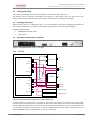
Figure 3: UHP-8000 satellite router – rear view
1.6.1
Overview
UHP-8000
UHP-1000
“A”
Tx
Tx
IF combiner
USB
TAP
TDMA Rx
LAN
LAN “A”
DC
LAN “B”
MCPC Rx
UHP-1000
“B”
IF divider
Rx
Tx
USB
TDMA Rx
USB “A”
USB “B”
LAN
DC
Power supply “A”
Power input “A”
Power supply “B”
Power input “B”
MCPC Rx
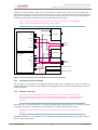
Figure 4 Standard internal configuration of UHP-8000 router
All the interfaces are located on the rear panel of the device. The indicators are located on the front panel.
Indication of each integrated router is located on the front panel of the chassis and similar to the standard display
of UHP- 1000 router. Indications on the left side of the front panel are related to the router "A", the indications on
the right side correspond to the router «B». The LAN and USB interfaces of each router are located on the rear
panel of UHP-8000 chassis and marked with «A» and «B», respectively.
© ROMANTIS 2015
8
www.uhp.net
UHP-8000 DUAL SATELLITE ROUTER
GENERAL DESCRIPTION AND INSTALLATION GUIDE, v3.2
USB PORTS MAY NOT BE AVAILABLE ON SOME VERSIONS OF UHP-8000 ROUTERS.
Depending on the ordered product’s configuration (mode of operation), interconnectivity of internal modules can
be configured with a different scheme. It applies only to connection of modulators and demodulators to interface
module (IF divider and combiner).
In the basic configuration (Figure 4) outputs of the modulators are summarized on the IF combiner ("Tx" output).
The IF combiner provides the transmission of IF signals, and can also transmit DC supply voltage and/or 10MHz
frequency reference for a BUC. Input signal from the "Rx" input is divided and fed to the inputs of all the
demodulators. The divider also provides a pass of DC and/or 10MHz reference frequency for LNB.
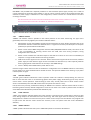
In HUB configuration (HBIC) (Figure 5) a high-speed demodulator of the satellite router “B” (acting as IC) is
connected to a «TAP» output of the IF combiner (“Tx” output) that allows synchronizing the router "B" with the
router “A” (acting as HB).
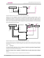
In dual Inroute configuration (ICIC) the “Tx” interface is used to input an Outroute signal from an external HB
module. This signal is divided and distributed to each of the high-speed demodulators for synchronization (see
Figure 6).
UHP-8000
UHP-1000
“A”
Tx
Tx
IF combiner
USB
TAP
TDMA Rx
LAN
LAN “A”
LAN “B”
DC
MCPC Rx
UHP-1000
“B”
IF divider
Rx
Tx
USB
TDMA Rx
USB “A”
USB “B”
LAN
DC
Power Supply “A”
Power input “A”
Power Supply “B”
Power input “B”
MCPC Rx
Figure 5 Internal configuration of UHP-8000 in Hub (HBIC) mode
1.6.2
Power connector (Power input A/B)
UHP-8000 router is powered with 100-240 VAC. UHP-8000 chassis has two independent power supplies (with
individual AC inputs) for each of the router respectively.
1.6.3
USB CONSOLE (USB A/B)
USB console ports provide local control of each of the integrated routers.
1.6.4
IF input (RX)
The RX interface is an input of the divider that distributes signals to the demodulators (see also 0). The router may
feed this input with 18 VDC power supply. Whether power source is on or off, the input can withstand external
© ROMANTIS 2015
9
www.uhp.net
UHP-8000 DUAL SATELLITE ROUTER
GENERAL DESCRIPTION AND INSTALLATION GUIDE, v3.2
voltage up to 50 VDC (power supply circuit is provided with a diode). Power supply circuit is protected with a
thermal fuse operating in case of short circuiting. After short circuiting is removed it may be required to disconnect
load from the Rx input for several seconds so as to allow the fuse to return to its initial state. Cable length and
cable quality (losses level) can affect the quality and possibility of receiving signals.
THE TOTAL CURRENT CONSUMED BY EXTERNAL EQUIPMENT SHOULD NOT BE IN EXCESS OF 750 MA. NORMALLY,
CURRENT CONSUMPTION BY DRO LNB - <150 MА, PLL LNB - <500 MА.
UHP-8000
UHP-1000
“A”
Tx
Tx
IF divider
USB
TAP
TDMA Rx
LAN
LAN “A”
LAN “B”
DC
MCPC Rx
UHP-1000
“B”
IF divider
Rx
Tx
USB
TDMA Rx
USB “A”
USB “B”
LAN
DC
Power Supply “A”
Power input “A”
Power Supply “B”
Power input “B”
MCPC Rx
Figure 6 Internal configuration of UHP-8000 in dual Inroute (ICIC) mode
1.6.5
LAN interface connector (LAN A/B)
LAN connectors are purposed for connecting to Ethernet switch using a straight cable. These connectors are
connected directly with respective LAN outputs of the integrated routers. Bit rate 10 or 100 and duplex mode are
software selectable.
1.6.6
Modulator output (TX)
TX OUT OUTPUT CAN FEATURE 24 VDC WITH A HIGH SHORT-CIRCUIT CURRENT. SHORT CIRCUITING CAN CAUSE
SPARKLE SPREAD AND BURNS. THIS VOLTAGE CAN DAMAGE MEASUREMENT EQUIPMENT IF IT IS NOT PROTECTED AT ITS
INPUTS. SUPPLYING EXTERNAL VOLTAGE TO THIS CONNECTOR IS OBJECTIONABLE . SUPPLYING MORE THAN 24 V IS
PROHIBITED.
The purpose of “Tx” interface depends on the factory-selected mode of operation (see 0). The interface provides
transmission of IF signals, 10 MHz reference and 24 VDC power supply (if activated on the router).
WARNING! THE SUPPLY VOLTAGE AND THE REFERENCE SIGNAL SHOULD BE ACTIVATED ONLY ON THE ONE OF THE
ROUTERS!
UHP-8000 modulators are compatible with most satellite transmitters/converters (BUC), except that require to
explicit “TX On” FSK command.
© ROMANTIS 2015
10
www.uhp.net
UHP-8000 DUAL SATELLITE ROUTER
GENERAL DESCRIPTION AND INSTALLATION GUIDE, v3.2
UHP-8000 is not provided with a separate protection on the transmitter power supply circuitry. Use is made of
current protection for the power supply adapter. In case of a short circuit the router is de-energized and then gets
restarted. If power supply is switched on in the configuration, restarts continue at 5 second interval until short
circuiting is removed.
ANY OPERATIONS WITH IF TX CABLE SHOULD BE PERFORMED WITH 24 V SUPPLY VOLTAGE TURNED OFF. OTHERWISE,
SELF-INDUCTION ACROSS A LONG CABLE CAN DAMAGE THE TRANSMITTER AND/OR ROUTER.
Figure 7 Satellite Router UHP-8000 series front view
1.6.7
“ERROR” Indicator
“ERROR” red indicator makes it possible to infer about problems in the router functioning. The type of the
generated problem can be judged by the number of indicator flashes:
1.
Demodulator cannot receive MCPC channel from the Hub (other Terminal). Please check AGC value in the
demodulator statistics to determine whether there is a signal from antenna (see description of reception
problems) to separate LNB and cable faults.
2.
Router cannot receive TDMA configuration from the HUB (TDM/TDMA network mode). The reason can be
in the non-availability of receiving channel from the HUB, CRC errors during reception, wrong
configuration of the Terminal.
3.
Router cannot calculate time shift with respect to the HUB. The reason can be in the non-availability of
reception or a large number of CRC errors during reception.
4.
HUB cannot receive signal from this terminal. Please check transmit signal level of the terminal, whether
power supply and the reference signal for the transmitter are switched on (or off if required), whether
DTTS or geographical coordinates are set correctly in the TDMA settings.
5.
Unit is in Backup state of Redundancy mode. Not an error.
Continuous signal means that the router has hardware or configuration errors. If ERROR indicator is continuously
lit upon power on it means hardware failure of UHP occurred. That prevents software from starting. Try to power
it off and power on again.
1.6.8
“STATUS” Indicator
“STATUS” green indicator indicates the router’s operation mode. This indicator is always flashing. If it does not
flash it means that the router is not functioning (please check power supply). Slow flashing (once every second)
means router’s normal operation. Faster flashing (3 times every second) means that a Telnet remote control
session is established (in this case USB console does not operate until session is over).
Fast (6 times every second), simultaneous flashing of “ERROR” and “STATUS” indicators means that the router is
functioning with the factory default configuration. Access to the router in this mode is possible either via USB of
via IP-address 192.168.222.222 (mask 255.255.255.248 or /29).
1.6.9
“LOCK” Indicator
“LOCK” green indicator indicates whether the router receives a channel from the central station. If there are CRC
errors during reception of information from the channel (e.g. with weak signal from the antenna), the indicator
extinguishes for a fraction of a second at every error. If there are too many errors the indicator may not glow at all
in spite of the fact that the router receives the channel (in this case please check the router demodulator
statistics).
1.6.10
“TDMA” Indicator
“TDMA” yellow indicator flashes every time a TDMA data placket is received via RX interface.
© ROMANTIS 2015
11
www.uhp.net
UHP-8000 DUAL SATELLITE ROUTER
GENERAL DESCRIPTION AND INSTALLATION GUIDE, v3.2
1.6.11 “SCPC” Indicator
“SCPC” yellow indicator flashes every time a SCPC data placket is received via RX interface.
1.6.12 “TX” Indicator
“TX” yellow indicator flashes every time a data placket is transmitted in the MCPC mode, and also a blank packet –
in the TDMA mode (if no data is available for transmission).
© ROMANTIS 2015
12
www.uhp.net
UHP-8000 DUAL SATELLITE ROUTER
GENERAL DESCRIPTION AND INSTALLATION GUIDE, v3.2
2.
OPERATIONS
2.1
Operational limits
Table 1 Operational limits
Limits
#
Parameter
1
3
4
5
6
7
8
9
PSU Input voltage
Output current at Tx Out interface
Input voltage on the Tx Out interface
Output current at Rх SCPC or RX TDMA
Input voltage on other interfaces
Operational temperature
Relative humidity (@ 250С)
Atmospheric pressure (mm Hg)
Mechanical impacts (acceleration with an amplitude
not exceeding 1,25 mm):
- in a range 0,5 – 15 Hz:
- in a range 15-40 Hz:
- in a range 40-300 Hz:
10
2.2
Minimum
100 VAC
0С
0%
720
Maximum
240 VAC
2A
24 V
0,75 А
18 V
+40 0C
90%
770
2,45 m/s
5,88 m/s
14,7 m/s
Preparation for use
2.2.1
Unpacking
Before opening the packaging please check the safety of a transport container. If there is any visible damage of
packaging you should keep it as long as the delivered equipment will be properly tested.
Unpack the router in the following order:
1.
Extract from a cardboard box the router and power cord.
2.
Store all packing materials for further storage or shipment of equipment.
3.
Check equipment for the presence of any possible damage resulting from transportation.
4.
Check the completeness of supply in accordance with the packing slip.
2.2.2
Installation
UHP-8000 Router is designed for installation in a 19” telecommunication rack or on a suitable flat surface.
Make sure you have enough free space for ventilation of the power supply and the router (not less than 2 cm).
While installing the router inside the computer or other systems we recommend using forced cooling to guarantee
the normal thermal environment of the router.
2.2.3
Connecting to external devices
All wire connections must be performed before powering up the router. IF cable connectors should be screwed to
the router without any use of any mechanical instruments. Please, avoid excessive force while connecting IF
cables.
WARNING! DO NOT CONNECT OR DISCONNECT ANY CONNECTING CABLES TO THE ROUTER WITH THE POWER ON. THIS
CAN LEAD TO A FAILURE OF THE ROUTER AND CONNECTED DEVICES.
© ROMANTIS 2015
13
www.uhp.net
UHP-8000 DUAL SATELLITE ROUTER
GENERAL DESCRIPTION AND INSTALLATION GUIDE, v3.2
BUC
ETHERNET SWITCH
UHP-8000
LNB
Tx
(24V, 10MHz)
LAN “A”
LAN “B”
User’s equipment
Rx
(18V)
Figure 8 Example of router’s connection in a basic mode of operation.
Typically, the router UHP-8000 is connected to individual RF frequency equipment (ODU). In such
configuration IF output of the modulator is connected to the power amplifier BUC, and the input of
high-speed demodulator to LNB. The router will supply the BUC with 24V power and 10MHz reference
signal. Also, the router may provide LNB with 18V DC power. The user’s equipment should be connected
to the router via Ethernet switch or hub, if you plan to connect only one device, it can be connected
directly with Ethernet cross-over cable.
BUC
ETHERNET SWITCH
UHP-8000 HB/IC
LNB
IF divider
IF divider
(24V, 10MHz)
Tx
LAN “A”
LAN “B”
User’s
equipment
Rx
(18V, 10 MHz)
UHP-8000 IC/IC
Tx
LAN “A”
LAN “B”
Rx
Figure 9 Example of router's connection in Hub mode (with 3 Inroutes)
In the Hub mode with several chassis (HBIC+ICIC) Rx inputs and Tx of these routers outputs should be connected to
RF equipment via IF dividers as it is shown on the Figure 9. Such dividers have to ensure by-pass of DC and 10 MHz
reference signal.
2.2.4
Powering on
In a few seconds after powering the router it is ready for use. Readiness of the router will be confirmed by
"STATUS" LED indicator (blinking with a period of 1 second), as well as by single flashes of "ERROR" indicator,
meaning a lack of reception of the receiving carrier.
With factory setting the router is configured as TDM/TDMA terminal. The router requires change of mode of
operation (if necessary) and/or configuration of respective network parameters before login into satellite
networks.
The easiest way to configure the router is using its HTTP access via its LAN port.
© ROMANTIS 2015
14
www.uhp.net
UHP-8000 DUAL SATELLITE ROUTER
GENERAL DESCRIPTION AND INSTALLATION GUIDE, v3.2
2.2.5
Local access to router via HTTP interface
HTTP (WWW) interface allows configuration key parameters and monitoring its actual status of the router. Local
Web page of the router can be accessed from any Internet browser.
By default, UHP-8000 router is configured with IP-address 192.168.222.222 with mask 255.255.255.248 (/29).
Respectively, the computer should be configured with an address, e.g. 192.168.222.217 with the same mask.
In case the satellite routers have been preconfigured at the factory on customer’s request such routers may have
different default IP address. In such case the respective IP addresses will be listed in the passport of the router. If
it’s impossible to connect the router with any of specified addresses please reset the router to factory settings.
2.2.6
Local access via USB
When router is connected to a computer via a USB cable the computer creates a serial COM port. The port number
can be found in the Device Manager. To access the port use can be made of either the OS-integrated terminal
(Hyperterminal) or third-party terminal programs.
With the first connection of UHP-8000 Router to PC the system may request the device’s driver (not required for
Windows 7 and newer OS). UHP.INF driver can be downloaded from our web site.
While working with the port from the terminal program the data rate and control parameters can be set to any
value since they are ignored.
WITH USB OS PROTOCOL STACK – THERE IS A PECULIARITY WHICH LEADS TO “HANGING” OF THE USB-PORT IF IT
CARRIED AN ACTIVE SESSION AND THE CONNECTED DEVICE (ROUTER) AT THIS MOMENT WAS REBOOTED. IN THIS CASE
YOU HAVE TO LOG OUT FROM THE TERMINAL PROGRAM AND LOG IN AGAIN. YOU CAN AVOID THIS BY CUTTING OFF THE
SESSION BY “HANG-UP” COMMAND AND ONLY THEN RESTART THE ROUTER USING RESET BUTTON OR VIA POWER
SUPPLY CIRCUIT.
2.2.7
Remote Telnet access
Remote access to the configuration can be performed using Telnet protocol. The connection can be provided to
any of IP addresses that are set on the router. UHP-8000 supports simultaneously only one Telnet session The
router auto-terminates the session after a certain time of inactivity. The time can be set in the configuration. by
default it is 10 minutes.
2.2.8
Command Interface
Please refer to the Command Interface manual applicable for the respective version of SW and activated mode of
operation of UHP router. The Command Interface manuals are available for download and online use on Romantis
website: http://www.uhp.net/en/support/docs.
© ROMANTIS 2015
15
www.uhp.net
UHP-8000 DUAL SATELLITE ROUTER
GENERAL DESCRIPTION AND INSTALLATION GUIDE, v3.2
3.
OPERATIONS
UHP Routers belong to the class of unattended equipment and during its operation does not require any special
staff exploitation. When operated as SCPC station or TDM/TDMA terminal the satellite router does not require any
changes of settings or it is configured remotely from the Hub. The tasks of operational staff are limited to the
following:
3.1
Monitoring of climatic environment of operation, ensuring the absence of dust, preventing the ingress of
moisture on the surface of the device. Should provide unrestricted air access to router for cooling.
Cables connected to the device must not suffer any significant impact on the connections of the router.
All connectors must be properly attached and secured.
Software updates
One of the key advantages of UHP satellite routers is the ability to extend the functionality by updating the
software. Software updates also include fixes for known bugs and improving the algorithms of the system.
3.2
Powering off
To power the router off the Power Supply should be disconnected from AC power. If the device is powered by a
low-voltage DC source, it can be powered off by disconnecting the DC cord from DC IN connector of the router.
3.3
3.4
Safety instructions for operations
Connect and disconnect all the cables only when router is powers off;
Do not block ventilation holes of the router, as this could lead to overheating of the device;
Clean the router by dry cloth, do not use liquid wipes or cleaners;
Router must be installed on a stable and flat surface;
Do not install on or nearby the router any glasses, vases and other containers containing liquid;
Do not try to repair the router and do not use it for other purposes;
There are no serviceable components inside, opening a case is not permitted;
Servicing by qualified personnel only;
Actions in case of fire
In case of fire or any smoke of the router please immediately power off the device and if necessary, use
extinguishing tools that are intended for electrical circuits.
© ROMANTIS 2015
16
www.uhp.net
UHP-8000 DUAL SATELLITE ROUTER
GENERAL DESCRIPTION AND INSTALLATION GUIDE, v3.2
4.
TROUBLESHOOTING
Table 2 Troubleshooting guide
Symptoms
Router doesn’t work
Possible reasons
Actions
AC power beyond the limits of allowed
values
Power cord is broken
Check AC power voltage
Power Supply failure
Short-circuit in transmit cable
Check PSU cables.
Verify if output DC Voltage is in nominal range.
Replace PSU module
Check PSU cables.
Contact your nearest dealer or service center for
advanced support.
Power off and power on the router.
Contact your nearest dealer or service center for
advanced support.
Disconnect and check Tx cable
Software failure
Reset software to factory defaults
Incorrect configuration
Check Rx frequency and symbol rate.
IF cable failure
Check Rx cable and make sure that its connectors
are properly connected to the LNB and the router.
LNB is not powered
Check if LNB power is switched on
Disconnect Rx IF cable from LNB and make sure that
12-18 VDC is available on the connector.
Check Rx level in the statistic of the demodulator.
No carrier on the satellite or its level is
insufficient.
Verify availability of the carrier and its level with
spectrum analyzer.
Contact Hub administrator and investigate if the
carrier is properly transmitting and local weather
conditions not attenuate the signal.
Measure carrier signal to noise level with a
spectrum analyzer.
Verify if antenna is properly pointed to the satellite
and there are no obstacles in the direction to the
satellite.
Check the integrity of the film of antenna’s feed
horn and absence of moisture in it.
Replace LNB to the spare one
The quality of reception may temporary decrease
during intensive rainfall, fog or thunderstorm
cloudiness.
Check if there is no snow or ice on the antenna
surface and on the feed horn.
Check C/N in demodulator’s statistics.
Verify if antenna is properly pointed to the satellite
and there are no obstacles in the direction to the
satellite.
Check the integrity of the film of antenna’s feed
horn and absence of moisture in it.
Router Failure
ERROR indicator lights
constantly after
power on.
Router restarts every
3-5 seconds.
No reception from
the satellite (indicator
LOCK is off, single
flashes of ERROR
indicator)
Router can’t start the software
Low Rx carrier level
High rate of errors of
Rx path (LOCK
indicator is not
lighting constantly)
LNB failure
Bad weather conditions
Low signal to noise level
© ROMANTIS 2015
17
Check PSU cables and output voltage of PSU.
Replace a cable.
www.uhp.net
UHP-8000 DUAL SATELLITE ROUTER
GENERAL DESCRIPTION AND INSTALLATION GUIDE, v3.2
Symptoms
Possible reasons
Actions
Low Rx carrier level
Interferences
Station is not
transmitting
(Reception is normal:
LOCK indicator is
lighting, but TX
indicator is off)
Station is not
transmitting
(Reception is normal:
LOCK indicator is
lighting, TX indicator
is blinking, but
transmission is not
received by
Hub/opposite station)
Other symptoms
Check Eb/No in demodulator’s statistics.
Contact Hub administrator and investigate if the
carrier is properly transmitting and local weather
conditions do not attenuate the signal
Check Tx frequency and symbol rate of the
modulator. Make sure that transmission is enabled
Wrong network setting
Transmission of the terminal is not
allowed by Hub (only for TDM/TDMA
terminal)
IF Tx cable failure
Contact Hub administrator
BUC is not powered
BUC failure
Check if BUC power is switched on
Disconnect Tx IF cable from BUC and make sure that
24 VDC is available on the connector.
Replace the BUC on the spare one
Other reasons
Contact your dealer or service center
Check Tx cable and make sure that its connectors
are properly connected to the BUC and the router.
In many cases, reinstalling system software allows to restore a satellite router functionality, which may need reset
to the factory default configuration. If the recovery of software cannot be implemented successfully, or if this
operation does not eliminate the defect, it is necessary to illuminate the faulty device and replace it by new device.
4.1
4.1.1
Replacement of modules
Common recommendations
Repair of satellite router is carried out by replacing defective units (PSU or a router) or the whole product.
Replacement must be carried out only on original and compatible units, supplied by the manufacturer. After
replacing the power supply the router is immediately ready for further operation. In case of a satellite router
replacement it has to be reconfigured to the network parameters in accordance with Section 2.2.
4.1.2
Safety instructions
Repair by replacing blocks of satellite router must be carried out by qualified personnel only and with powered off
device only.
© ROMANTIS 2015
18
www.uhp.net
UHP-8000 DUAL SATELLITE ROUTER
GENERAL DESCRIPTION AND INSTALLATION GUIDE, v3.2
5.
STORAGE, TRANSPORTATION AND DISPOSAL
Storage and transportation of satellite routers must be performed in original packaging. Equipment can be stored
and transported in pallet with height not more than 10 devices.
Storage and transportation should comply with the following conditions:
- humidity is not more than (80 ± 3)% at a temperature (25 ± 2)°C;
- limiting low temperature of storage (minus 40 ± 2) ° C;
- limiting high temperature of storage (50 ± 2) ° C.
- atmospheric pressure 720 ÷ 770 mm. Hg.
Utilization of satellite routers must be in accordance with the rules for disposal of industrial or consumer
electronics in accordance with applicable law.
© ROMANTIS 2015
19
www.uhp.net