1
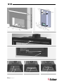
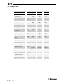
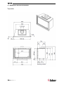
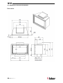
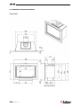
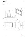
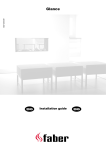
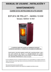
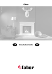
Presence GB IE 40011221-1138 Installation Guide and users manual GB IE UK IRL Installation Guide 1<<<< UK IRL 1.1 1.2 1.3 1.4 2<<<< 1.5 1.6 UK IRL 1.7 1.8 2.1 2.2 2.3 3<<<< 2.4 2.5 UK IRL A B 2.6 3.1 3.2 4.1 4.2 4<<<< 3.3 UK 1 IRL Introduction • The fire can only be installed by a competent person in accordance with the Gas Safety Installation and Use regulations. We urgently advise you to read this installation manual properly. This appliance complies with the guidelines for European gas appliances (Gas Appliances Directive) and bears the CE mark. 2 Safety instructions. • • • • • • • • The appliance should be placed, connected and annually checked in accordance with these installation instructions and valid national and local Gas Safety (Installation and Use) Regulations . Check whether the data on the registration plate are in agreement with the local type of domestic gas and pressure. It is not permitted to change the adjustments or the construction of the appliance! Do not place any additional imitation logs or glowing coals on the burner or in the combustion chamber. The appliance has been designed for ambience and heating purposes. This means that all surfaces of the appliance , including the glass, can become very hot (hotter than 100 °C). An exception to this are the bottom of the appliance and the controls. Do not place any combustible materials within 0.5 m. of the radiation of the appliance and ventilation grills. Due to natural air circulation of the appliance, moisture and volatile components from paint, building materials, floor coverings etc. that haven’t yet set, can be drawn through the convection system and can be deposited on cold surfaces as soot. That is why you should not use the appliance shortly after a renovation. The first time the appliance is switched on, Let the fire run on maximum setting for several hours so that the lacquer coating will have an opportunity to set and possible vapours released can be safely removed by ventilation. We advise 5<<<< • 3 you to be outside the room as much as possible during this process! Please note that: 1. all transport packaging should be removed. 2. children or pets should not be present in the room. No extra ventilation is required, due to the fact that the input of the appliance is not exceeding 7,0 kW. Installation requirements 3.1 The fire The fire is tested for installation without a hearth. Make 2 non combustible supports on the left and the right side of the burner unit. (see fig. 1.1) 3.2 Chimney breast The appliance must be built into a non combustible existing or a new to be constructed false chimney breast. For the dimensions of the builders opening see fig.1.7. framed frameless A= 670mm 670mm B= Min. 100mm Min. 100mm C= 337mm 337mm+wall thickness D= max. 60mm wall thickness E= 460mm 430mm Combustible shelf F= min. 350mm G= max.150mm If the shelf depth is greater than 150mm, add 50 mm to shelf clearance height for every 25 mm increase in shelf depth For the dimensions of the fire see chapter 11 till 14. The false chimney breast must be ventilated on top and bottom with a minimum opening of 200cm2. The false chimney breast and its construction may not rest on the appliance. Therefore always use a lintel for a brick build chimney. For the minimum dimensions see fig 1.8. For the finish, use special stucco (min. 100°C resistant) or glass fibre wallpaper to prevent discoloration or cracks etc. Recommended drying time: for plaster is a minimum of 24 hours per mm of coat applied. UK IRL 3.3 C. The frame now can be hung on the support. (see fig.3.3) Requirements flue system and outlets Top outlet The flue connector collar is for connection to a 125 mm (5 inch) internal diameter pipe or liner according BS EN 1856. The minimum effective height of the flue system must be 3 meter. Rear outlet In case of an installation in a masonry chimney convert the outlet to the rear outlet. Therefore unscrew the top outlet and fit the rear outlet on the fire. Take care to fill up all the holes with the screws.(see fig.1.3) To collect the debris, there must be a minimum gap of 23 mm behind the appliance Use the supplied glass fibred-seal to seal the fire box to the builders opening.(see fig.1.2) 4.3 Batteries. The battery pack is fixed on a chain inside the burner unit on the right side. (see fig.2.2) Pull the chain to remove it. To avoid overheating take care that the battery pack always is positioned correctly in the burner unit. 4.4 Placing the appliance Take the installation requirements into account (see chapter 3). Masonry chimney Cut out the opening so that the appliance can be fitted easily. prepare the 2 non combustible supports on the left and the right side in the builders opening (see fig. 1.1) Chimney The top of the chimney must always be higher then the top of the roof. For a Top outlet connection Pull a 5 inch liner into the chimney. Fit the fire in the builders opening and connect the liner on the top outlet. 4 For a Rear outlet installation Fit the fire in the builders opening, use the supplied glass fibred-seal to seal the fire box to the builders opening.(see fig.1.3) Preparation and Installation instructions 4.1 Gas connection The gas connection must comply with locally valid standards. We advise Pipe work from the meter to the appliance must be of adequate size. An isolator is factory fitted, no further isolation device is required. Place the gas connection in such a way that it is accessible for service and the burner unit can be disconnected at all times. 4.2 • • • • • • • Preparation of the appliance Remove the packaging of the appliance. Clear a safe space to store the glass. Remove the glass (see chapter 5) and take the separately wrapped parts out of the appliance. Prepare the gas connection. Prepare the flue connection. If necessary convert to rear outlet (see chapter 3.3). If necessary convert to framed version. Therefore: A. Remove the build in frame (see fig.3.1) B. Fit the frame support. (see fig.3.2) 6<<<< Do a gas leakage test on all joints and check burner and inlet pressure. See chapter 7 before closing the chimney Reconstruct the wall of the chimney. 5 Removing the glass • • • • • Place the suction discs onto the glass Remove the cover strips on the left and right side by pushing the top (see fig.1.4) Remove the cover strips on the left and right hand side (see fig.1.5) Remove the sealing cord from the groove (see fig.1.6) Lift the glass up and move slowly forward, now you can take the glass out. To replace the glass repeat the process in reverse order. Remove all Fingerprints from the glass, these will be burned into it once the hearth is used. UK 6 IRL Placing the log set, decoration material It is not allowed to add different or more materials to the combustion chamber. Always keep the pilot burner free from decorative material! Do not toss all the decorative material onto the burner all at once, as the very fine dust may block the holes in the burner. 6.1 • • • • 6.2 7.3 Checking the burner pressure and the inlet pressure Check whether the burner pressure and the inlet pressure measured agree with the data indicated on the registration plate 7.4 Imitation logs Spread the vermiculate preferably by hand over the tube burner in the burner-slot. The surface of the vermiculate may be very slightly elevated from the burner plate but it should be levelled throughout the entire length. Place the imitation logs according to instructions. (see fig.4.1) or the instruction card) Start the pilot and main burner, according to the instructions in the user’s manual. Assess whether the flame distribution is correct. Place the glass and check the flame picture into the appliance Pebbles Place the pebbles over the burner in the burner holder. Do not cover the grid in the front. Spread the pebbles evenly to a double layer. The surface of the pebbles may be very slightly higher then the burner tube (see fig.4.2) • Place the glass and check the flame picture. • 7 7.2 Checking for gas leakage. Check all connections and joints for possible gas leaks by means of a gas leak detector or spray Checking the installation 7.1 Checking the ignition of the pilot burner, main burner. Start the pilot and main burner following the instructions in the user’s manual. • Check whether the pilot light is properly positioned above the main burner and is not covered by vermiculite and imitation log or pebbles. • Check the ignition of the main burner at full mark or low mark. (the ignition should take place quickly and easily). 7<<<< • • • • • • Measuring the inlet pressure: Turn off the gas control. Get access to the burner unit by removing the glass, log set and bottom plates as described in chapter 8.4. Open the pressure gauge nipple B (see fig.2.6) a few turns and connect a pressure gauge hose to the gas control valve. Fit the burner plate with burner (see fig. 2.4). Carry out the measurement when the appliance is on at full gas mark and when it is on the pilot light. If the inlet pressure is too high you are not permitted to connect the appliance. 7.5 Measuring the burner pressure: Only perform this measurement if the inlet pressure is correct. • Follow the steps as described in chapter 7.4 to get access to the burner unit. • Open the pressure gauge nipple A (see fig.2.6) a few turns and connect a pressure gauge hose to the gas control valve. • The pressure must agree with the value indicated in the technical data in chapter 10. In case of deviations, get in touch with the manufacturer. *Close the pressure gauge nipples and check these for gas leaks. 7.6 Spillage test Carry out the lighting procedure and turn the fire to high. • Allow to warm up for 15 minutes and then using a smoke match with holder set 100% inside the middle part on top of the appliance (see fig.2.1) between the trim and the glass frame. The installation is satisfactory if most of the smoke is drawn into the tube. • Repeat the test with doors and windows to the premises open and closed, and with any extractor fans in • UK IRL • 8 8.1 8.2 the same room or adjacent rooms running on high. Check if any other open flue appliances and flues in the same or adjacent rooms function correctly when this appliance is alight. Annual maintenance Service and cleaning: Check and clean if necessary after checking: • The pilot light • The combustion chamber • Spillage (see chapter 7.5) • The glass (see chapter 8.3) • For debris (see chapter 8.4) • The logs for possible fractures • The outlet • Replace: If necessary the vermiculite. 8.3 Cleaning the glass Most of the deposits can be removed with a dry cloth. You can use ceramic hob cleaner to clean the glass. Note: prevent fingerprints on the glass. these will be burned into it once the appliance is used and cannot be removed anymore! 8.4 Check and cleanup debris To get access to the debris area, remove the: 1. glass (see chapter 5) 2. log set 3. burner unit. Therefore: Remove the bottom plates in the front and at the back (see fig. 2.3) Unscrew 4 screws (2 at the left and 2 at the right) and remove the burner plate including the burner. (see fig. 2.4) Disconnect the gas. Unscrew 13 screws of the burner unit and 2 screws of the switch and remove the burner unit. (see fig. 2.5) Now the debris area is accessible. To replace all the parts repeat the process in reverse order. 8.5 Final check Carry-out the check-up according to the instructions in chapter 7 “checking the installation. 8<<<< 9 Conversion to a different type of gas (e.g. propane) This can only be done by installing the proper burner unit. for this purpose get in touch with your supplier. Always mention the type and serial number of the appliance when ordering. UK IRL 10 Technical data Gas category II2H3+ II2H3+ II2H3+ Type of appliance B11AS B11AS B11AS G20 G30 G31 5,2 5,2 5,2 5.8 5,6 5.6 2 2 2 (76%) (76%) (76%) 4 4 4 mbar 20 30 37 l/h 542 150 181 380 340 Reference gas Input - Nett - Gross kW Efficiency class NOx class inlet pressure Gas rate at 15ºC and 1013 mbar Gas rate at 15ºC and 1013 mbar Burner pressure at full gr/h mbar 9,5 20 25,7 Injector main burner mm 2,1 1,3 1,3 Minimum screw mm 1,3 0,85 0,85 OP9030 OP9222 OP9222 125mm 125mm 125mm (5 inch) (5 inch) (5 inch) Gas control valve GV60 GV60 GV60 Gas connection 8mm 8mm 8mm 4x AA 4x AA 4x AA (1,5V) (1,5V) (1,5V) 9V 9V 9V mark Pilot assembly Diameter outlet 9<<<< mm Batteries receiver V Batteries sender V UK IRL 11 Dimensions Presence Frameless Top outlet 10 < < < < UK IRL 12 Dimensions Presence Frameless Rear outlet 11 < < < < UK IRL 13 Dimensions Presence Framed Top outlet 12 < < < < UK IRL 14 Dimensions Presence Framed Rear outlet 13 < < < < UK IRL Users manual 14 < < < < UK IRL 1.1 1.6 15 < < < < 1.2 1.3 1.4 1.5 1.7 1.8 UK IRL 1.9 2.3 16 < < < < 2.0 2.1 2.4 2.2 2.5 UK IRL 15 Introduction Because this appliance is a source of heat, air circulation will arise. That is why it is important that you do not use the fire shortly after a renovation. By natural air circulation moisture and volatile components from paint, building materials, floor coverings etc. that haven’t set yet, are sucked up. These components can be deposited on cold surfaces as soot. The first time you should use the fire depends on various circumstances. Consult your gas fitter on this matter. 16 Cleaning and Maintenance • • The appliance will have to be cleaned and serviced and the proper functioning checked by a gas fitter. The outside frame of the fire can be cleaned with a clean damp cloth. 16.1 Cleaning the glass • Dismount the glass according to the description in the installation instructions. • Remove the deposit with a clean dry cloth. If necessary, a special ceramic cleaning agent can be used. Note: prevent the making of finger marks on the glass. These cannot be removed once the fire has burnt them into the glass! 17 Safety Instructions for the User • The appliance has been designed for atmospheric and heating purposes. This means that all surfaces of the fire, including the glass, can become very hot (hotter than 100 °C). An exception to this is the on-off switch of the fire • If the fire has been switched off, wait for at least three minutes before re-igniting it again. • If the fire switches off with no known cause, wait for at least 15 minutes before re-igniting the fire again. If this happens repeatedly, get in touch with your gas fitter. • The fire should not be used if: - The glass is damaged or has been removed. - The combustion chamber is open. • Don’t place any inflammable materials in the combustion chamber. 17 < < < < • • • • Never change the position of the log set and never add more decorative materials or carrara pebbles than have been supplied with the appliance. If the fire is switched on, the pilot light should always be visible! Don’t place any curtains, clothes, laundry, furniture or other inflammable materials in the neighbourhood of the appliance. The minimum safe distance is 100 cm. Don’t allow children to use the remote control unit without adult supervision. Fit a suitable fireguard if there are children, old people or persons with limited mobility present in the same room. 18 First time the fire is operated Before ignition, remove all stickers, protective wrappings and, if present, rubber protective padding from the glass. Make sure the room is properly ventilated the first time the fire is switched on. Burn the appliance at the highest position for some hours so that the lacquer coating will have an opportunity to set and possible vapours released can be safely removed by ventilation. Keep children and pets outside the room during this process! 18.1 Remote control unit – general remarks The appliance has been supplied with a remote control set; The receiver and the gas control are located underneath the burner. Access only allowed by a competent person • The remote control has been provided with 3 keys (fig.1.4). All functions of the fire can be operated with these keys. • If the transmission is successful, the receiver will emit a sound signal. • With the On/Off switch (fig. 1.1) the fire can always be switched off. • Switch in O position –, if the fire is not in use for a longer period. • When using the thermostat/timer function, the wall bracket supplied (fig. 2.3/2.4/2.5) should always be placed within 4 metres of the appliance . 18.2 batteries The battery pack for the receiver is fixed on a chain and store on the right side underneath the burner unit. (see fig. 1.3) UK IRL 18.3 Placing the batteries • Pull on the chain to take out the battery pack (fig 1.3) • Unscrew and open the battery pack. Place 4 AA/LR6 Alkaline long life batteries • Close the pack and place the battery pack back in the appliance. • To avoid overheating the battery pack must always positioned underneath the burner unit.(see fig 1.2) 18.4 Placing the batteries in the remote control unit • Remove the lid at the back of the remote control unit. (fig. 1.5) • Place a 9Volt MN1604/6LR61 Alkaline long life battery. • Close the lid. 18.5 Replacing empty batteries • Handset: if the indication BATT appears in the top left corner of the display screen, the batteries of the remote control unit need to be replaced. • After replacing the battery in the handset, the settings of the thermostat and timer function have been reset to the factory settings. • Receiver:3 short sound signals will be heard when the engine is on to indicate that the batteries of the receiver are nearly run down. • When the battery supply is very low, the remote control unit will switch off the appliance completely. This will not happen if the supply is interrupted. • It is possible that the transmitter code will have to be set again after replacing the batteries, see chapter 19.2 for instructions. 19 Setting the controls on the remote control unit. 19.1 Time setting: • • • • • Press the - and the -key simultaneously (fig. 1.6) The display screen will blink now Press the -key to set the hours (fig. 2.1) Press the -key to set the minutes (fig. 2.2) Wait or press the OFF- key to terminate this function (fig. 2.0). 18 < < < < 19.2 Setting the transmitter code on the remote control unit: Press the reset button of the receiver with a pointed object, until the second signal is audible. Now press the -key on the remote control unit (fig. 2.1), within 20 seconds. If a sound signal is audible, the transmitter code has been set. 19.3 Temperature/clock setting (standard °C/24hours): The alteration of the temperature indication on the display screen from °C/24hours to °F/12hours and the other way around is done in the following manner: • Press the OFF-key and the -key (small flame) simultaneously until the indication is modified (fig. 1.7). 20 Basic functions of the Remote Control Unit 20.1 Switching on the fire • • • Press the z- key and the -key simultaneously, until a sound signal is audible (fig. 1.9). The start-up procedure will be executed now. During this period the receiver will emit a repetitive sound signal. The fire will start burning at the highest position automatically now. 20.2 Adjusting the flame height • • Keep the -key pushed in to increase the flame height step by step. (fig. 2.1) Keep the -key pushed in to lower the flame height step by step and/or to switch back to the pilot light. (fig. 2.2) 20.3 Switching off the fire • Press the OFF-key and the fire will be switched off completely. (fig. 2.0) Move the toggle switch (fig. 1.1) to position – O, if the fire is not in use for a longer period. 21 Thermostat and Timer Function The following settings are possible in the thermostat function: • Day temperature (ÏTEMP) • Night temperature (dTEMP) If the thermostat function is used, the remote control unit should be placed in the wall bracket (fig. 2.4/2.5/2.6), this should be UK IRL mounted within 4 metres of the appliance in the same room. The timer function (TIMER) can make the thermostat function once or twice on day temperature and one or twice on night temperature during a period of 24 hours. Factory settings thermostat and timer: Day temperature 23° Night temperature (appliance doesn’t switch on) Timer P1 Ï 6:00 (getting up) P1 d 8:00 (departure) P2 Ï 16:00 (homecoming) P2 d 22:00 (night) Example setting one switch period: Day temperature 21° Night temperature (appliance doesn’t switch on) Timer P1 Ï 8:00 (getting up) P1 d 22:00 (night) 21.1 Additional functions The display screen on the remote control unit always shows one of the functions below: By pressing the the SET-key (fig. 1.8) briefly, the various functions can be shown consecutively. MAN t ÏTEMP dTEMP t TIMER MAN t manual operation. If the indication MAN is shown in the display screen, the fire can adjusted to a higher or lower flame position by pressing the -key or the -key (fig. 2.1 or 2.2), see chapter. 20.2 and 6.3. NOTE: By pressing the - key or the -key (fig. 2.1 or 2.2), the manual operation is switched on and the active thermostat and/or timer programmes are switched off. In this “clock thermostat” function the duration of the periods for day and night temperatures is set within 24 hours. 21.2 Setting day and night temperatures • Move the SET-key (fig. 1.8) step by step to ÏTEMP. • Now keep the SET-key (fig. 1.8) pushed in for a long time until the temperature indication in the display screen starts to blink. • In accordance with your wishes, increase the Day temperature with • • • the -key (fig. 2.1) or lower it with the -key (fig. 2.2). Note! The lowest temperature that can be set is 5 ºC. If you don’t want the fire to switch on at night, keep pressing the -key (fig. 2.2) until the sign - - appears in the display screen. • Save the settings by pressing the OFF- key (fig. 2.0) or wait for ten seconds. 21.3 Programming the timer setting • Move the SET-key (fig. 1.8) step by step to TIMER. • Now keep the SET-key (fig. 1.8) pushed in for a long time until the time indication in the display screen starts to blink and P1 Ï is visible. • Set the starting time P1 (getting up) ÏTEMP Day temperature If the indication for day temperature is shown in the display screen, the thermostat will make sure the environmental temperature agrees with the settings for day temperature. • dTEMP Night temperature If the indication for night temperature is shown in the display screen, the thermostat will make sure the environmental temperature agrees with the settings for night temperature. TIMER • Timer function • 19 < < < < the -key (fig. 2.1) or lower it with the -key (fig. 2.2). Press the SET–key (fig. 1.8) again, now dTEMP appears in the display screen. Now keep the SET-key (fig. 1.8) pushed in for a long time until the temperature indication in the display screen starts to blink. In accordance with your wishes, increase the Night temperature with of the day temperature with the key (fig. 2.1) for the hours and with the -key (fig. 2.2) for the minutes. Now press the SET-key (fig. 1.8) again, now P1 d (departure) will appear in the display screen and the time indication will start to blink and now set the starting time. For setting the 2nd period, press the SET–key (fig. 1.8) and P2 Ï (homecoming) will appear in the display screen, the time indication will start to blink and now set the starting time. If a 2nd period setting is not desired, save the settings by UK IRL • • • pressing the OFF- key (fig. 2.0) or wait for ten seconds. Press the SET–key (fig. 1.8) again and now P2 Ï (homecoming) will appear in the display screen, the time indication will start to blink and now set the starting time. Press the SET–key (fig. 1.8) again, now P2 d (night) appears in the display screen, the time indication will start to blink and now set the starting time. Save the settings by pressing the OFFkey (fig. 2.0) or wait for ten seconds. 22 Checkpoints in case of Malfunction If the remote control unit of the fire does not function properly, check the following points first: 1. Is the toggle switch (fig. 1.1) set to position I ? 2. Check the battery- (chapter. 18.5) 3. Check whether the receiver responds to the remote control unit. If necessary, reset the receiver. Therefore: Briefly pull the battery pack out and remove the batteries out the holder wait 1 min. before replacing the batteries , now the receiver is reset. If the remote control unit or the fire itself does not function properly after all these checks, we refer you to your gas fitter. 20 < < < < UK IRL 21 < < < < UK IRL 22 < < < < www.faber.nl – [email protected] Saturnus 8 NL - 8448 CC Heerenveen Postbus 219 NL - 8440 AE Heerenveen T. +31(0)513 656500 F. +31(0)513 656501