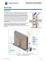
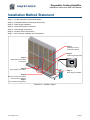
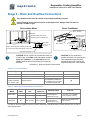
1
Evaporative Cooling Humidifier SKV Series Installation Instructions and User Manual Read and save this manual SKV Evaporative Cooling Humidifier-140508.docx Evaporative Cooling Humidifier Installation Instructions and User Manual Foreword Neptronic Company Overview Founded in 1976, we’re a private corporation that designs, manufactures and distributes products for the HVAC industry. Our product line includes intelligent controllers, electronic actuators, actuated valves, humidifiers and electric heaters. Our products are designed and manufactured by over 250 dedicated employees in our 7,500 m2 (80,000 ft2) state-of-the-art facility located in Montreal, Canada. Using a vertical integration model, our entire manufacturing chain is under one roof from software and hardware development, to SMT circuit board assembly, to sheet metal fabrication, to product testing ensuring that our products are engineered to last. We currently hold several national and international patents and with our continued commitment to research and development, we provide innovative products and technologies for the ever-evolving challenges of the HVAC industry. Exporting over 70% of our sales, we have an exclusive distribution network around the globe that provides comprehensive solutions to our worldwide customers. About the Manual These installation and operation instructions have been developed to facilitate the installation of the Evaporative Cooling Humidifier. The strict application of these instructions will ensure conformity of your installation and operation as per the manufacturer's recommendations. The application of these instructions is one of the conditions for the application of the warranty. The application of these instructions does not ensure, at any time conformity to procedures, regulation or local codes, regarding electric installation and connection to local water supply. 2014©: All rights reserved. This document cannot be reproduced totally or partially by any means whether, electronic, mechanical, photocopy, recording or other, without prior written authorization of Neptronic. www.neptronic.com Page | i Evaporative Cooling Humidifier Installation Instructions and User Manual Health and Safety Instructions General This manual has been written to ensure correct, safe and sustainable operation of the SKV Evaporative cooling humidifier and is intended for use by engineers and technical personnel trained by Neptronic or their official agents. This manual must be read thoroughly before specifying, designing, installing or operating an SKV Evaporative Cooling Humidifier. Please retain for reference and should you have any questions please contact Neptronic and we will be pleased to assist. ! The triangular symbol with the word WARNING: is used to designate danger of severe or lethal consequence. ! The circular symbol with the word CAUTION: is used to designate danger of injury, or to warn of hazardous operating condition. Electrical Warning Message WARNING: Risk of electric shock. Do not access. Disconnect Evaporative Cooling Humidifier prior to opening the access door. All work concerned with electrical installation MUST only be performed by skilled and qualified technical personnel such as an electrician or a technician with appropriate training. The customer is always responsible for ensuring the suitability of the technical personnel. Please observe local regulations concerning the provision of electrical installations. Health & Safety Installation, maintenance, repair work or de-commissioning should only be carried out by appropriately qualified and properly trained technical personnel. Any risks or hazards relating to the system, including during installation and maintenance, should be identified by a competent Health & Safety representative who shall be responsible for introducing effective control measures as necessary. The customer is responsible for ensuring that the installation of the equipment complies with all local regulations. ! CAUTION: Maintenance personnel must be trained by Neptronic or their official agent and it is the customer’s responsibility to ensure their suitability. Failure to use properly trained personnel may lead to a hazardous operating condition. WARNING: Danger of electrocution! Danger of contact with live parts when the unit is open. Always isolate all water and electrical supplies to the system before commencing any maintenance or repair. Isolate power and water immediately if there is any sign of water leaking from the unit. Protective Equipment Please refer to the Health and Safety Executive for recommendations with regard to Personal Protective Equipment and for information on the Control of Substances Hazardous to Health COSHH. www.neptronic.com Page | ii Evaporative Cooling Humidifier Installation Instructions and User Manual Hygiene IMPORTANT: Refer to local Health and Safety regulation and codes on the control of Legionellosis in water systems. In the absence of such, ASHREA guideline 12-2000 does provide recommendations. If not adequately maintained, water systems can support the growth of micro-organisms including the bacterium that causes Legionnaires’ disease. SKV has been designed to reduce as much as possible any possible risk of legionellosis growth. Users also share the responsibility in reducing the risk of legionellosis; users are required to: Conduct a risk assessment of the complete water system. Implement proper control of the water system. Connect SKV to a clean and chlorinated water supply main. Avoid stagnant water. Avoid water temperatures that increase risk of Legionella growth. Clean and disinfect the system regularly, refer to service section of the present Installation Instructions and User Manual. ! WARNING: Risk of Legionnaires’ disease which can be fatal. SKV Evaporative Cooling Humidifier must be installed, operated and serviced in accordance with this Installation Instructions and User Manual. ! WARNING: In the event that the SKV Evaporative Cooling Humidifier is turned off for prolonged periods (more than 24 hours), ensure that any water storage tanks and pipe-work supplying the unit are drained, unless they supply other systems which ensure a regular renewal of water in the system. Failure to do so may result in stagnation of the water and contamination that might cause Legionnaires' disease, which can be fatal. It is the responsibility of the person on whom the statutory responsibility falls to determine all control and preventative measures outlined in this manual. Correct Use Neptronic systems and its products are designed only for humidification use. Any other application is not considered appropriate for the intended purpose. The manufacturer cannot be made liable for any damage resulting from incorrect use. www.neptronic.com Page | iii Evaporative Cooling Humidifier Installation Instructions and User Manual Lists and Table of Contents Contents Overview ..................................................................................................................................................................... 1 Operation ................................................................................................................................................................ 1 Benefits ................................................................................................................................................................... 2 Features .................................................................................................................................................................. 2 Nomenclature ......................................................................................................................................................... 2 Specifications.......................................................................................................................................................... 3 Dimensions and Weights ........................................................................................................................................ 3 Handling and Packaging ............................................................................................................................................. 4 Handling .................................................................................................................................................................. 4 Correct Lifting Method ............................................................................................................................................ 4 Inspection ............................................................................................................................................................... 4 Unpacking ............................................................................................................................................................... 4 Installation Overview................................................................................................................................................... 5 Local Regulations ................................................................................................................................................... 5 List of Supplied Accessories ................................................................................................................................... 5 Installation Method Statement .................................................................................................................................... 6 Stage 1 – On Site Assembly of Evaporation Module ............................................................................................. 7 Stage 2 – Evaporation Module Positioning and Mounting...................................................................................... 9 General Considerations ...................................................................................................................................... 9 Positioning the Evaporation Module ................................................................................................................... 9 Stage 3 – Water Supply Installation ..................................................................................................................... 10 Stage 4 – Drain and Overflow Connections ......................................................................................................... 11 Stage 5 – Power Supply Connections .................................................................................................................. 12 Stage 6 – Electrical Control Connections ............................................................................................................. 13 Safety Contact Connections ............................................................................................................................. 13 On/Off Operation .............................................................................................................................................. 14 Modulating Operation ....................................................................................................................................... 14 Mounting of the Enclosure ................................................................................................................................ 14 Stage 7 – SKV Controller Installation and Configuration...................................................................................... 15 Menu Overview ................................................................................................................................................. 15 Main Menu Configuration ................................................................................................................................. 16 Main Menu - Controls ....................................................................................................................................... 17 Main Menu - System Setup .............................................................................................................................. 18 Main Menu - Diagnostics .................................................................................................................................. 19 Main Menu - Installer ........................................................................................................................................ 21 Firmware Update .............................................................................................................................................. 22 Alarms ............................................................................................................................................................... 23 Servicing and Maintenance ...................................................................................................................................... 24 Preventative Maintenance .................................................................................................................................... 24 Verification List ................................................................................................................................................. 24 Water Sampling and Testing (Hygiene)............................................................................................................ 24 Disinfection ....................................................................................................................................................... 25 De-scaling ......................................................................................................................................................... 26 www.neptronic.com Page | iv Evaporative Cooling Humidifier Installation Instructions and User Manual Troubleshooting ........................................................................................................................................................ 28 Water leakage from the tank ................................................................................................................................ 28 Water carries over into air stream ........................................................................................................................ 28 Loss of performance ............................................................................................................................................. 28 Scale build up on the surface of the media .......................................................................................................... 28 Module pump is not functioning ............................................................................................................................ 28 Exploded View and Parts List ................................................................................................................................... 29 Evaporative Cooling Humidifier ............................................................................................................................ 29 Media Panels ........................................................................................................................................................ 30 Recommended Spares List .................................................................................................................................. 30 General Conditions of Sale and Warranty ................................................................................................................ 31 General warranty policy ............................................................................................................................................ 31 Special agreement on components under warranty ................................................................................................. 31 Notes ........................................................................................................................................................................ 32 List of Illustrations Illustration 1- Evaporative Media ............................................................................................................................... 1 Illustration 2 - Humidifier Overview ............................................................................................................................ 1 Illustration 3 - Dimensions and Weights .................................................................................................................... 3 Illustration 4 - Installation Stages............................................................................................................................... 6 Illustration 5 - Evaporation Module Assembly ........................................................................................................... 7 Illustration 6 - Positioning and Mounting.................................................................................................................... 9 Illustration 7 - Water Supply Installation .................................................................................................................. 10 Illustration 8 - Drain and Overflow Connections ...................................................................................................... 11 Illustration 9 - Power Supply Connections ............................................................................................................... 12 Illustration 10 - SKV Controller Wiring Diagram ...................................................................................................... 13 Illustration 11 - Mounting the Controller Enclosure ................................................................................................. 14 Illustration 12 - Evaporative Cooling Humidifier Exploded View ............................................................................. 29 List of Tables Table 1 - Nomenclature ............................................................................................................................................. 2 Table 2 - Water Supply and Drain Connection Specifications .................................................................................. 3 Table 3 - Evaporation Module Specifications ............................................................................................................ 3 Table 4 - P Trap Installation .................................................................................................................................... 11 Table 5 - Water Drain and Overflow Specifications................................................................................................. 11 Table 6 - Power Supply Specifications .................................................................................................................... 12 Table 7 - Passwords ................................................................................................................................................ 16 Table 8 - Water Dilution (determine interval and number of cycles) ....................................................................... 22 Table 9 - Proposed plan of control and disinfection according to results of microbiological testing of water ......... 25 Table 10 - Evaporative Cooling Humidifier Part Numbers....................................................................................... 29 Table 12 - Media Panel Numbers ............................................................................................................................ 30 Table 13 - Spare Parts Replacement ...................................................................................................................... 30 www.neptronic.com Page | v Evaporative Cooling Humidifier Installation Instructions and User Manual Overview Operation The humidifier consists of an Evaporative Module that is installed in an air handling unit (AHU) or a duct. Water enters the evaporation module from the main water supply and reaches the top of the unit. The water distribution system disperses water over the Evaporative Module like a waterfall. Warm dry air passes through the wet media, evaporates water, and raises the humidity level. The SKV also offers up to 21.5°F (12°C) of cooling as a result of the transfer of energy when the water evaporates. 65% 75% Cooled & Humidified Air 85% Any particle or contamination present in the air flow can accumulate and clog the media. For this reason, Neptronic recommends proper air filtration, typically and at least 5 microns (EU5). On some critical applications, such as medical sites or laboratories, a finer filtration might be required. Warm & Dry Air Evaporative media 95% In order to prevent any possible carry over, an optional droplet separator can be added at any time during the life of the SKV. Neptronic does recommend the use of droplet separator when air velocity is above 600FPM (3m/sec). Water Droplet separator Illustration 1- Evaporative Media Illustration 2 - Humidifier Overview www.neptronic.com Page | 1 Evaporative Cooling Humidifier Installation Instructions and User Manual Benefits Very low energy consumption (< 1kW) Free cooling up to 21.5°F (12°C) Hygienic operation Custom modular design to fit exact dimensions of AHU or duct ensures minimal use of blanking plates, which obstruct air passage and increase pressure drop through the evaporation module Environmentally friendly Low pressure drop Simple and low maintenance. Easy access to water distribution on top, no tools required to remove media panels, one screw to remove pump skid Fast and efficient drain pump with the ability to lift the drain water when no slope is possible for the drain water pipe All parts in contact with water are made of stainless steel and designed for life Uses any type of water, Deionised (DI), Reverse Osmosis (RO) or tap water Features Custom designed with Humidisoft to meet your specific duct/application dimensions Energy transfer during water evaporation results in free cooling up to 21.5°F (12°C) Low energy (< 1 kW) consumption ensuring an environmentally friendly application Four humidification efficiencies: 65%, 75%, 85% and 95% Inorganic and inflammable material (UL900 Class 1) Minimum blanking plates resulting in lower pressure drop 5 microns PP pre-filter and silver ion dosing cartridges prevent microbial growth Staging valves: up to 5 for flexible and accurate control Includes SKV electronic controller o Microprocessor based, field configurable controller o BACnet communication (optional) o On/Off or modulating control type o Master/slave configuration for up to 4 Evaporative Modules o Easy connection with only one 6-wire control cable o User-friendly, menu-driven LCD (128 x 64) o Real-time clock and SD card for scheduler, trending and history log o Firmware upgrade via SD card o Stainless steel controller enclosure rated IP56 for outdoor installations Nomenclature Table 1 - Nomenclature SKV R 95 C 1 D C Type: R = Recirculation D = Direct Feed O = OEM Media Efficiency: 65 = 65% efficiency 75 = 75% efficiency 85 = 85% efficiency 95 = 95% efficiency Controller: C = Standard Controller B = BACnet Controller _ = None No. of Stages: 1 = 1 Stage 2 = 2 Stages 3 = 3 Stages 4 = 4 Stages 5 = 5 Stages Droplet: D = Droplet separator _ = Not included Voltage: A = 120Vac C = 230Vac www.neptronic.com Page | 2 Evaporative Cooling Humidifier Installation Instructions and User Manual Specifications Table 2 - Water Supply and Drain Connection Specifications Specification Description Water Supply Size Ø3/4’’ (20mm) garden hose, male Maximum Water Supply Pressure 70 PSI (4.8bar) Maximum Water Supply Temperature 68°F (20°C) Drain Pump Inlet Size Ø3/4" (20mm) Overflow Outlet Size Tank size less than 94” (239cm): Tank size greater than 94” (239cm): Ø1.5" (3.8cm) Ø2.0" (5.1cm) Table 3 - Evaporation Module Specifications Specification Evaporation Module Frame Material Description Stainless Steel Grade 304 Evaporation Media – Material Glass fibre material bonded with a special inorganic compound Evaporation Media – Fire Rating European Fire rating: (EN13501-1 & EN13238): Euro class A2, s2, d0 North America Fire rating: UL900 class 1 (by ETL) Evaporation Media – Hygiene Evaluation EN ISO 846, VDI6022 Part I, suitable for use in HVAC-systems (by ILH Berlin) B Dimensions and Weights C A Illustration 3 - Dimensions and Weights Evaporative Module dimensions are calculated and customized to the actual size of the duct dimension using Humidisoft. Please refer to drawing attached and referenced with the Humidisoft project number for dimensions and weights for your SKV. www.neptronic.com Page | 3 Evaporative Cooling Humidifier Installation Instructions and User Manual Handling and Packaging Handling Always handle the SKV Evaporative Cooling Humidifier with care and keep within its original packaging for as long as possible, prior to installation. It must be stored under cover and protected from any possible damage, from dust, rain or frost. Correct Lifting Method Lifting or handling must only be carried out by trained and qualified personnel. Ensure that the lifting operation has been properly planned, risk assessed and that all equipment has been checked by a skilled and competent Health & Safety representative and that effective control measures are put in place. WARNING. It is the customer's responsibility to ensure that operators are trained in handling heavy goods and to enforce the relevant lifting regulations. ! WARNING. Any personnel handling or lifting the SKV Evaporative Cooling Humidifier must follow the Lifting Operations and Lifting Equipment Regulations 1998 and Approved Code of Practice L113. The regulation imposes duties on employers and self employed persons and persons who have control, to any extent of lifting equipment. Refer to dimensions and weights as indicated on the SKV nameplate as well as the submittal drawing for system dry weights. Inspection Upon receipt, and once packaging material has been removed, an inspection must be carried out to ensure that no damage occurred during transit. Any damage should be reported with no delay to your Neptronic representative. Unpacking Upon customer request and following transit maximum size for large dimension SKV Evaporative Cooling Humidifier, evaporation media panels and evaporation module frames are delivered on a separate pallet. In this case, the evaporation module will have to be assembled on site. ! CAUTION. Risk of malfunction, evaporation media should not be cut or crushed during handling and installation. www.neptronic.com Page | 4 Evaporative Cooling Humidifier Installation Instructions and User Manual Installation Overview ! WARNING: Failure to observe manufacturer's installation recommendations will invalidate the manufacturer’s warranty. Local Regulations Lifting or handling MUST be carried out by trained and qualified personnel. Ensure that the lifting operation has been properly planned, assessed for risk and that the equipment has been checked by a competent Health & Safety representative, and that effective control measures are in place. ! It is the customer’s responsibility to ensure that the operators are trained in handling heavy goods and to enforce the relevant lifting regulations. The Evaporative Cooling Humidifier MUST always be handled and lifted with care and should remain in its original packaging for as long as possible prior to installation. The Evaporative Cooling Humidifier package may be carried using a forklift from the underside. Caution should be exercised to ensure a balanced load before lifting. List of Supplied Accessories Water supply stainless steel reinforced hose 24" (600mm) along with 1/2’’ NPT (13mm) female hose connection. Water filter assembly, 5 microns PP pre-filter and silver ion dosing anti bacterial cartridges. Installation Instructions and User Manual www.neptronic.com Page | 5 Evaporative Cooling Humidifier Installation Instructions and User Manual Installation Method Statement Stage 1 – On Site Assembly of Evaporation Module Stage 2 – Evaporation Module Positioning and Mounting Stage 3 – Water Supply Installation Stage 4 – Drain and Overflow Connections Stage 5 – Power Supply Connections Stage 6 – Electrical Control Connections Stage 7 – SKV Controller Installation and Configuration Stage 1 Assembly on Site of Evaporation Module Stage 2 Positioning and Mounting Stage 4 Water Drain and Overflow Connections Stage 5 Power Supply Connections Stage 3 Water Supply Installation Stage 6 Electrical Control Connections and Controller Installation Stage 7 SKV Controller Configuration Illustration 4 - Installation Stages www.neptronic.com Page | 6 Evaporative Cooling Humidifier Installation Instructions and User Manual Stage 1 – On Site Assembly of Evaporation Module On site assembly of the SKV evaporation module is necessary when its height and width are incompatible with maximum shipping dimensions. CAUTION. Risk of injury. Some sheet metal parts might present sharp edges and some handling and assembly will require working with a ladder. We recommend wearing protective gloves and any appropriate other protective equipment during handling and assembly of the SKV evaporation module. ! We recommended installing the SKV evaporation module into a waterproof AHU or duct section. The SKV evaporation module is a self-contained humidifier/cooler however; leaks might occur at the water and drain connection point. ! WARNING: Risk of malfunction. SKV evaporation module must be level in the 2 plan directions. Bottom tank, main support beam and pump skid will usually be pre-assembled at the factory before delivery. However, the main support beam for the evaporative media panels as well as the pump skid can be easily removed and re-installed as indicated in steps 1 and 9. Tools required: Philips screw driver size #2 & #3 Wrench sizes 7/16’’ (11mm) and 5/16’’ (8mm) Level Step 4 Top frame 4C 3C 5C 6C Step 5 Media panels 2C 1C 2B 3B 4B 5B 1B 4A 1A 2A 5A 6B 6A Step 6 Panel link bracket (at least 1 per level) 3A Step 7 Holding rail (1 per level) Step 2 Side frame sections (factory assembled if H=W) Step 9 Pump skid assembly (factory assembled) Step 3 Side frames (x2) Step 1 Main support beam (factory assembled) Step 8 Water distribution drawers Step 11 Water distribution hoses (1 per drawer) Step 10 Drain manifold assembly (factory assembled) Illustration 5 - Evaporation Module Assembly www.neptronic.com Page | 7 Evaporative Cooling Humidifier Installation Instructions and User Manual Step 1 (optional): Main Support Beam The evaporation media panel’s main support beam is assembled at the factory. However its position can be adjusted depending on the evaporative media panels’ depth. To do so, remove the screws’ protective caps and remove the Philips screws. Adjust, re-install the screws and re-insert the protective caps. Step 2 (optional): Side Frame Sections If the height of the evaporation module is greater than its width, assemble the side frame section along with the holding rail support. Install the four lock washers and nuts and then tighten using a 7/16’’ (11mm) wrench. Step 3: Side Frames Assemble the two side frames onto the bottom tank. Install the six lock washers and nuts on each side and then tighten using a 7/16’’ (11mm) wrench. Step 4: Top Frame Install the top frame onto the two side frames. ! CAUTION. This part can be very long and might require the help of 2 people to be safely installed. Install the three lock washers and nuts on each side. Do not tighten the nuts, as a final adjustment of the assembly will be required after all the media panels and water distribution drawers are installed at steps 5 and 8. Step 5: Media Panels Install the media panels onto the evaporation module frame. We recommended installing them row by row, and not column by column. Make sure that each media panel is properly installed into the one below. Step 6: Media Panel Link Bracket Install at least one media panel link bracket per level. This bracket is designed to re-enforce the structure by holding together the media panel and holding rail. Loosen the top two Philips screws from adjacent media panel frames, insert the bracket, and then tighten the two Philips screws. Step 7: Holding Rail Install one holding rail per level. Insert the holding rail onto at least one link bracket and engage the latches into the holding rail supports on both sides. Note: In case the SKV evaporation module is equipped with a droplet separator (air velocity above 600FPM), repeat steps 5 to 7 for the installation of droplet separator panels. Step 8: Water Distribution Drawers Install the water distribution drawers onto the top frame (step 4) and adjust the top frame position to ensure proper sliding of the drawers. Confirm proper positioning of the top frame (step 4) and tighten the three nuts on each side. Step 9 (optional): Pump Skid The pump skid assembly is installed at the factory before shipping. If you need to remove it, first disconnect the electrical quick connector of the drain and then remove the Philips screw. Step 10 (optional): Drain Manifold The drain manifold assembly is installed at the factory before shipping. If you need to remove it, disconnect the drain hose from the bottom tank, and open the clamp maintaining the drain manifold assembly by removing the 5/16’’ (8mm) nut. The drain manifold assembly can be directed either on the right-hand side (by default) or on the left-hand side of the bottom tank. Step 11: Water Distribution Hoses Install the water distribution hoses between the top drawers and the circulation pump manifold or solenoid valve outlets, by pushing each hose into the push-in connectors. www.neptronic.com Page | 8 Evaporative Cooling Humidifier Installation Instructions and User Manual Stage 2 – Evaporation Module Positioning and Mounting General Considerations Consider the following points before deciding the location for the Evaporative Cooling Humidifier steam distribution system: Plan a location that is easy to access and permits an easy inspection and servicing of the Evaporative Cooling Humidifier. Do not install the Evaporative Cooling Humidifier where failure of the appliance could cause damage to the building structure or to other expensive equipment. Verify that the construction of the duct or AHU wall is suitable to support the maximum weight when the evaporation module is wet. We recommend installing the SKV evaporation module into a waterproof AHU or duct section. The SKV evaporation module is a self-contained humidifier/cooler however; leaks might occur at the water and drain connection point. Install a drain outlet connection at its lowest point within the cooling or humidification section. Construct the drain pipe in such a way that there is no water accumulation and stagnation. Make provision either on one side or both sides of the AHU or duct for water supply, drain line(s), and electrical conduit to the evaporation module. The SKV Evaporative Cooling Humidifier accepts the water supply, drain, overflow piping, and electrical connections from the right-hand or left-hand side of the evaporation module. Positioning the Evaporation Module Level the evaporation module properly in order to ensure proper distribution of water (see Illustration 6 - Positioning and Mounting). Make sure that the drain outlet is at the lowest point of the unit. Do not leave any empty space around the evaporation module. In case there is some empty space, install blanking plates to prevent air passage. The unit is custom made to fit the AHU or duct dimension however; to allow easy installation and service a space of 2in (51mm) on both sides and 2in (51mm) on top of the evaporation must be planned. Provide a minimum access of 24" (600mm) downstream of the evaporation module for installation, inspection, commissioning, and maintenance. Also provide the same clearance, 24" (600mm) upstream, for easy commissioning and maintenance. Provide access to the sides of the unit through doors. Level in this direction Attachment point (x4) Level in this direction Illustration 6 - Positioning and Mounting Mounting the Evaporation Module Secure the evaporation module to the AHU or duct by screws and bolts (not supplied) of suitable size. Attach the evaporation module in such a way that it will not vibrate or move under air velocity and pressure. www.neptronic.com Page | 9 Evaporative Cooling Humidifier Installation Instructions and User Manual Stage 3 – Water Supply Installation ¾’’ G connection S/S flexible hose 24in long supplied ½’’ female connection Water supply Silver ion dosing Shut off valve (not supplied) Prefilter 5µ Water pre-treatment cartridge supplied Piping (not supplied) To be installed outside of duct / AHU Illustration 7 - Water Supply Installation Note: Do not over tighten hose fittings as this may damage the seals. Install an isolation valve (not supplied) on the water line near the evaporative module's inlet for easy maintenance and servicing. We recommend fitting a pressure gauge for commissioning and maintenance. Flush the water line thoroughly before connecting the feed water pipe-work to the evaporation module. Follow the water supply specifications as mentioned below: o Water Supply Size - Ø3/4’’(20mm), garden hose o Maximum Water Supply Pressure - 70psi (4.8bar) o Maximum Water Supply Temperature - 68°F (20°C) Connect the humidifier to a clean drinking water supply. o The humidifier is capable of operating with a wide range of water qualities such as reverse osmosis (RO), or tap water. If the humidifier is connected to hard water, it will result in scale build-up on the evaporative module and will require frequent cleaning and replacement. o If the supplied water is treated with reverse osmosis or de-ionization filtration, control the total dissolved solid contents in the water, otherwise water acts as a solvent agent resulting in rapid evaporation and media degradation. o Water conductivity of the water should be between 100 and 550 microS/cm at 68°F (20°C). o For direct feed, water conductivity should not be lower than 150 microS/cm at 68°F (20°C). If it is lower, mix the treated water with tap water to achieve the recommended conductivity. Alternatively, install SKV with recirculation (SKVR) and setup the dilution cycle accordingly. www.neptronic.com Page | 10 Evaporative Cooling Humidifier Installation Instructions and User Manual Stage 4 – Drain and Overflow Connections Any installation work must be carried out by suitably qualified personnel. Risk of flooding. Never connect drains to a closed pipe work. Always install a tundish to provide a suitable air gap. Recirculation Model Direct Feed Model Safety overflow drain Ø 1-½’’ (38mm) Overflow Slope 2º minimum from horizontal Combined drain outlet can be directed to right or left hand side P trap height H = 1'’ for 1'’ w.c. stat. press. Main drain Slope of 2º is required for overflow (gravity) drain If no slope can be fitted, separate the 2 drain lines Main drain Ø 2'’ (51mm) P trap Height H= 1'’ for 1'’w.c. stat. Press. Open drain Open drain is required CAUTION: Do not combine the overflow and drain to a common pipe if the width of the evaporation module is below 30’’ (762mm) or, if the main drain has to be lifted to the drain inlet of the building (if no slope can be fitted). Illustration 8 - Drain and Overflow Connections ! ! CAUTION: Do not combine the overflow and drain to a common pipe. Two independent traps should be installed for drain and overflow and sized according to the Table 5 below. Table 4 - P Trap Installation Drain Type P Trap Main drain separated Overflow separated Required if there is no drain pump Always required Main drain and overflow combined to a common pipe Always required Recirculation Direct Feed if evaporation module over 30” (762mm) or if main drain is not lifted to drain inlet x x Table 5 - Water Drain and Overflow Specifications SKV Model Recirculation Tank width Drain outlet size Overflow outlet size ≤70’’ (1.8m) Ø ¾’’ (19mm) Ø1.5’’ (38mm) >70’’(1.8m) Ø ¾’’ (19mm) Ø2’’ (51mm) All Ø2’’ (51mm) Ø1.5’’ (38mm) Direct feed Minimum slope 2° or 1.4’’for every 3ft of horizontal run. (35mm for 1m run) 2° or 1.4’’for every 3ft of horizontal run. (35mm for 1m run) Trap size 1’’ for every 1’’ w.c of static pressure (25mm / 250Pa) 25mm for every 250Pa of air static pressure For AHU or duct with negative pressure, specific precautions should be taken to isolate the drain line in order to avoid any back flow. www.neptronic.com Page | 11 Evaporative Cooling Humidifier Installation Instructions and User Manual Stage 5 – Power Supply Connections WARNING. All work concerned with electrical installation should only be performed by skilled and qualified technical personnel, such as electricians or technicians with appropriate training. The customer is responsible for ensuring their suitability. WARNING. Risk of electric shock. Isolate all power supplies before installation and maintenance of the SKV Evaporative Cooling Humidifier. Electrical box on evaporation module Power cable should pass through water tight bushing. Power supply terminal block 120Vac or 240Vac 1ph 60Hz as per voltage indicated on name plate (by others) Illustration 9 - Power Supply Connections Table 6 - Power Supply Specifications Model Voltage (V) Current (A) SKVR Recirculation model 120 – 1ph 5.5 240 – 1ph 3 SKVD Direct feed model 120 – 1ph 1 240 – 1ph 0.5 You MUST externally fuse all incoming power supplies for over current protection. Isolate the electrical supply for the purpose of emergencies and servicing. We recommend installing a disconnect switch within 1m (3.3ft) of the humidifier. The isolator must have a contact separation of at least 1/8’’ (3mm). Please observe local codes and regulations concerning the provision of electrical installations. The installation engineer must ensure the following: Use of copper power conductors only. Size of the power conductors are suitable for the maximum current supplied. Incoming power cable is secured via suitably sized cable gland. Each terminal connection is secured firmly with a cable ferrule. Humidifier cabinet has an uninterrupted or unbroken electrical ground. Do not use the evaporation module’s frame to connect to ground. www.neptronic.com Page | 12 Evaporative Cooling Humidifier Installation Instructions and User Manual Stage 6 – Electrical Control Connections WARNING. All work concerned with electrical installation should only be performed by skilled and qualified technical personnel, such as electricians or technicians with appropriate training. The customer is responsible for ensuring their suitability. WARNING. Risk of electric shock. Isolate all power supplies before installation and maintenance of the SKV Evaporative Cooling Humidifier. SD1 SKV Master PCB LCD1 (by others) From TB 12-1 of 1st module From TB 12-2 of 1st module To TB 12-3 of 1st module From TB 12-4 of 1st module To TB 12-5 of 1st module To TB 12-6 of 1st module Connector to LCD PCB TB6 Micro SD card purple To enable BACnet, insert jumper between pins 3 & 5 of JP2 TB5 TB4 TB3 TB2 TB1 Common 24 Vac 24 Vac - + RS-485 A+ (BACnet) B- Air Flow Switch High limit Humidistat Interlock On/Off demand contact NO NC 1 2 3 Analog Inputs (AI1 - AI3) Analog Output NO NC Service contacts Alarm contacts (by others) Illustration 10 - SKV Controller Wiring Diagram Safety Contact Connections Airflow switch contact should be wired between terminals TB4 1&2. If this contact opens, operation of the SKV unit will stop. The unit will display Airflow Switch open, but will not generate an alarm. High limit humidistat contact should be wired between terminals TB4 1&3. If this contact opens, operation of the SKV unit will stop and an Alarm message will be displayed. Interlock switch can be wired between terminals TB4 1&4. If this contact opens, operation of the SKV unit will stop and an Alarm message will be displayed. www.neptronic.com Page | 13 Evaporative Cooling Humidifier Installation Instructions and User Manual On/Off Operation For On/Off operation, connect the On/Off contact between TB4 1&5. If this contact opens, the SKV unit will turn off. If this contact closes, the SKV unit will operate. Modulating Operation Analog Whatever the source of the control signal (BMS, room or duct humidistat, room or duct thermostat, or a combination) the signal(s) should be connected between Common and Analog input 1, 2 and/or 3. These analog inputs are configurable at step 1A “Settings” of the Controls menu (see page 17). BACnet (network) If the control signal is from a BACnet network, the RS485 A+ & B- should be connected to network (TB5). The network control signal will have to be selected at step 1A “Settings” of the Controls menu (see page 17). Also refer to step 1E “BACnet” of the Controls menu (see page 17) to setup the communication parameters. Mounting of the Enclosure Illustration 11 - Mounting the Controller Enclosure www.neptronic.com Page | 14 Evaporative Cooling Humidifier Installation Instructions and User Manual Stage 7 – SKV Controller Installation and Configuration The power (on/off) and drain buttons are protected from accidental activation by a 3-second delay. The power or drain button must be pressed and held for 3 seconds to perform the related action. Menu Overview When the SKV controller is in operation, the unit displays three information screens. The Product Info, Modules and System Info screens are displayed for 3 seconds each and then remains on the System Info screen. Press the ▲ and ▼ buttons located to the right of the screen to manually scroll through each screen. Model Model Firmware Serial # SD ► SKV85R 0.20 14V010001 The first screen indicates the model #, firmware revision installed and the controller’s serial #. ▲ ▼ The SD icon appears if the controller detects a micro SD card. Current time and date are also displayed. 2014-Mar-02 15 :13 :23 Modules No. of modules Module 1 Module 2 SD ► 2 2 stages 3 stages The second screen provides basic information on the evaporation module(s). ▲ ▼ The SD icon appears if the controller detects a micro SD card. Current time and date are also displayed. 2014-Mar-02 15 :13 :23 System Info Room Humidity 45% RH Room Temp. 21°C ▲ Duct Humidity 40% RH ▼ Demand 100.0% Water flow 1000kg/h SD ► 2014-Mar-02 15 :13 :23 www.neptronic.com The third screen indicates the demand and water flow of the evaporative module(s). The SD icon appears if the controller detects a micro SD card. Current time and date are also displayed. Page | 15 Evaporative Cooling Humidifier Installation Instructions and User Manual Main Menu Configuration A. Press the Menu * button. B. Use the ▲, ▼ buttons to select the desired main menu category and press Enter . C. If password protection is enabled (see table below), enter the password and press Enter. If you enter the wrong password, the SKV controller displays an "invalid password" message. Table 7 - Passwords Mode/Menu Controls Installer System Setup Diagnostic Password 637 757 372 None Priority 1 2 3 4 Required Always required Required only if enabled at menu 1F Required only if enabled at menu 2E Not required Note: If a password of higher priority has already been provided; individual passwords will not be required. For example, if the Installer menu password has been validated already, access to other menus such as Controls will be unlocked automatically. D. Use the + and - buttons to increase and decrease the values. Use the ▲, ▼ buttons to scroll to the next or previous menu item. Values are saved as soon as a change is made E. Press the Menu * button to go back one menu. Press the Enter button to advance to the next sub-menu. F. To exit, press the Menu * button until you return to the menu overview or after 5 minutes of inactivity the controller will automatically exit the menu. Note 1: Available settings and range selections may vary depending on current configuration. The tables in the following sections display all the possible selections. The Notes/Conditions column indicates the conditions required for the associated setting to appear. Note 2: The Drain Schedule (Menu 2B) and Occupancy Schedule (Menu 2C) on page 18 do not support schedules that cross-over midnight during the same day. For example, Wednesday from 19:00 to 8:00 will stop at midnight. In this case you must configure 2 days as follows: Wed–19:00, Thu–00:00, Thu–08:00. www.neptronic.com Page | 16 Evaporative Cooling Humidifier Installation Instructions and User Manual Main Menu - Controls CONTROLS 1A) Settings 1B) Control Mode Settings Int.in RH, Int. in Temp, Network, Ext.AI1, Ext.AI2, Ext.AI3 Internal, Network, Ext.AI1, Ext.AI2, Ext.AI3 Room RH Src: Room Temp Src: High Limit Src: Feedback Signal: AI1 AI2 AI3 2-10Vdc 10°C (50°F) or 40% RH AI1, AI2, AI3, Network, None AI1, AI2, AI3, Network, None AI1, AI2, AI3, Network, None 0-10Vdc, 2-10Vdc 10.0 to 40.0°C (50.0 to 104.0°F) or 10 to 90% RH 0-10Vdc 0-10Vdc, 2-10Vdc, 0-20mA, 4-20mA 0.5°C (0.9°F) or 5.0% RH 0.5°C (0.9°F) or 5.0% RH 0.1°C (0.2°F) or 2.0% RH 0.5°to 5.0°C (0.9 to 9.0°F) or 1.0 to 20.0% RH 0.5°to 5.0°C (0.9 to 9.0°F) or 1.0 to 20.0% RH 0.5°to 5.0°C (0.9 to 9.0°F) or 1.0 to 20.0% RH 0-10Vdc 0-10Vdc, 2-10Vdc, 0-20mA, 4-20mA Occ.Setpnt: Prop.Ramp: Integral Ramp: Deadband: External signal: 1D) High Limit 1E) BACnet 1F) Password www.neptronic.com Range Int.Temp Internal Setpnt Signal: 1C) Room Sensor Default Control Mode: Setpnt Source: No additional settings RH Signal: Temp. Signal: Min.Temp Range: Max.Temp Range: n/a n/a 0-10Vdc 0-10Vdc -20°C (-4°F) +80°C (176°F) 0-10Vdc, 2-10Vdc, 0-20mA, 4-20mA 0-10Vdc, 2-10Vdc, 0-20mA, 4-20mA -50 to 100°C (-58 to 212°F) -50 to 100°C (-58 to 212°F) Signal: 0-10Vdc 0-10Vdc, 2-10Vdc, 0-20mA, 4-20mA Setpoint: Prop. Ramp: No additional settings MAC Address: Device Instance: Auto Baud Rate: Baud Rate: Fallback Timeout: Controls Menu 10 %RH 0.0 %RH 10 to 90 %RH 10 to 20 %RH n/a n/a 1 3153000 On 9600 2 min Off (Disable) 0 to 254 0 to 4194302 On (Enable), Off (Disable) 9.6k, 19.2k, 38.4k, 76.8k 1 to 15 minutes On (Enable), Off (Disable) Notes/Conditions Network option only available with BACnet models If Int. in Temp or Int. in RH at 1A “Control Mode”. Network option only available with BACnet models Network option only available with BACnet models Network option only available with BACnet models Network option only available with BACnet models If Int. in Temp or Int. in RH at 1A “Control Mode” and Internal at 1A “Setpnt Source”. If Int. in Temp or Int. in RH at 1A “Control Mode” and External (Ext. AI1, AI2, AI3) at 1A “Setpnt Source”. If Int. in Temp or Int. in RH at 1A “Control Mode” If Int. in Temp or Int. in RH at 1A “Control Mode” If Int. in Temp or Int. in RH at 1A “Control Mode” If External (Ext.AI1, Ext.AI2, Ext.AI3) at step 1A “Control Mode”. Only this option appears No settings to configure on this screen, if Network at 1A “Control Mode”. If AI1, AI2, or AI3 at step 1A “Room RH Src” If AI1, AI2, or AI3 at step 1A “Room Temp Src” If Int.in RH at 1A “Control Mode”, Network at 1A “Setpnt Source” and AI1, AI2, or AI3 at 1A “High Limit Src”. No settings to configure on this screen, if None at 1A “High Limit Src”. Available with BACnet models only Page | 17 Evaporative Cooling Humidifier Installation Instructions and User Manual Main Menu - System Setup Sub-Menu 2A) Clock 2B) Drain Schedule 2C) Occ.Schedule 2D) Measure 2E) Options www.neptronic.com Settings Default Range Time Format: Actual Time: Date: UTC diff: Daylight Saving: 12h 00.00 13:09:03 +4h Off 12h (AM/PM) or 24h 0 to 24 hours YY/MM/DD -12 to +14 hours On (Enable), Off (Disable) Drain schedule disabled n/a n/a Day: Monday Monday to Sunday Event 1: Unused Unused, Wait, Start Drain, Stop Drain | 00:00 to 23:59 Notes/Conditions The drain schedule is only available for Recirculation models with the Auto Drain (step 4C) set to Schedule in the Installer menu. The drain schedule is not available for Direct Feed models Each day of the week can have different events; up to 4 events each. The events displayed are configured and apply to the day that’s displayed. If you select Wait, Start Drain, or Stop Drain, a clock setting is displayed. Set the time/duration at/in which the unit can perform the drain task. An event cannot cross-over midnight, see Note 2 on page 16. Event 2: Unused Unused, Wait, Start Drain, Stop Drain | 00:00 to 23:59 Event 3: Unused Unused, Wait, Start Drain, Stop Drain | 00:00 to 23:59 Event 4: Unused Unused, Wait, Start Drain, Stop Drain | 00:00 to 23:59 Occupancy schedule disabled n/a n/a The drain schedule is only available when the Occupancy Schedule (step 4B) is set to ON in the Installer menu. Day: Monday Monday to Sunday Each day of the week can have different events; up to 4 events each. The events displayed are configured and apply to the day that’s displayed. Event 1: Unused Unused, Occup., Unoccup, Vacancy, Off | 00:00 to 23:59 Event 2: Unused Unused, Occup., Unoccup, Vacancy, Off | 00:00 to 23:59 Event 3: Unused Unused, Occup., Unoccup, Vacancy, Off | 00:00 to 23:59 Event 4: Unused Unused, Occup., Unoccup, Vacancy, Off | 00:00 to 23:59 Temp Units: Flow Display: Mass Flow Units: Setup Password: Alarm Beep: Key Press Beep: Contrast: Language: °F Mass Flow lb/h Off On On 5 English °C or °F % or Mass Flow kg/h or lb/h On (Enable), Off (Disable) On (Enable), Off (Disable) On (Enable), Off (Disable) 0 to 10 English or Français Wait = time before drain sequence can start. Start Drain = time at which drain sequence will start. Stop Drain = time at which drain sequence will stop. If you select Occup., Unoccup., Vacancy or Off, a clock setting is displayed. Set the time/duration at/in which the unit can perform the drain task. An event cannot cross-over midnight, see Note 2 on page 16. Occup. Unoccup. Vacancy Off = duration the unit remains in Occupancy mode. = duration the unit remains in Unoccupied mode. = duration the unit remains in Vacancy mode. = duration the unit remains Off. If enabled, the System Menu password is 372. Page | 18 Evaporative Cooling Humidifier Installation Instructions and User Manual Main Menu - Diagnostics Sub-Menu 3A) Functions Reset Alarm: No Range (* indicates no configuration; display only) Yes or No Start Drain Cycle: No Yes or No Disinfection Time: Start Disinfect. 15 min No 15 to 30 minutes Yes or No Cleaning Due On: YY-MM-DD * Last Cleaning: YY-MM-DD * Cleaning Done? No Yes or No Total Runtime Last Silver Ion 0000 h YY-MM-DD * Silv. Ion Changed? No Yes or No UV Lamp Due On: YY-MM-DD * Last UV Lamp: YY-MM-DD * UV Lamp Changed? No Yes or No Control Mode: Setpnt Source: High Limit Src: Setpnt : Demand: Room Temp: Room Humidity: High Limit Sensor: Demand: Current value Current value Current value Current value Current value Current value Current value Current value Current value * (Int.RH, Int. Temp, Network, Ext.AI1, Ext.AI2, Ext.AI) Settings Default 3B) Cleaning 3C) Service 3D) Inputs www.neptronic.com * Notes/Conditions Set to Yes to reset any alarms that have been restored and require a manual reset. Refer to Alarms on page 23. Set to Yes to start the drain sequence. The time required varies depending on various factors, such as size of tank, quality of drain and factory setting of drain completion time. “In Progress” is displayed until the cycle is completed. Set to Yes to start the disinfection sequence. The sequence fills the tank, and then runs the module(s) at 100% for the duration of the selected Disinfection Time. It then performs an auto-drain sequence and returns to normal operation. If during the Disinfection Time, the tank needs to be filled again, the timer will stop until the tank is filled. The date represents 3 to 12 months after setting “Cleaning Done?” to Yes. This “Cleaning Interval” is set by the Installer at step 4A in the Installer menu. A “Service Warning” appears 100 hours before the due date. A “Service Alarm” appears on the due date. Displays the date at which the “Cleaning Done?” was set to Yes. When the unit has been cleaned, set this value to Yes to reset the “Cleaning Due On” date and “Last Cleaning” date. Displays total number of hours the unit is in function. Displays the date at which the “Silv. Ion Changed” was set to Yes. When the Silver Ion cartridge has been changed, set this value to Yes to reset the “Last Silver Ion?” date. The due date is variable based on water flow and time in use. A “Service Alarm” appears on the due date. The date represents 1500 to 3000 hours after setting “UV Lamp Changed?” to Yes. The “UV Lamp Notice” (no. of hours) is set by the Installer at step 4A in the Installer menu. A “Service Alarm” appears on the due date. Displays the date at which the “UV Lamp Changed?” was set to Yes. When the UV lamp has been changed, set this value to Yes to reset the “UV Lamp Due On” date and “Last UV Lamp” date. * (Internal, Network, Ext.AI1, Ext.AI2, Ext.AI3) * (AI1, AI2, AI3, Network, None) * (mV) * (mV) * (mV) * (mV) * (mV) If External (Ext.AI1, Ext.AI2, Ext.AI3) at step 1A “Setpnt Source”. If External (Ext.AI1, Ext.AI2, Ext.AI3) at step 1A “Control Mode”. If External (Ext.AI1, Ext.AI2, Ext.AI3) at step 1A “Room Temp Src”. If External (Ext.AI1, Ext.AI2, Ext.AI3) at step 1A “Room RH Src”. If External (Ext.AI1, Ext.AI2, Ext.AI3) at step 1A “High Limit Src”. * (Opened or Closed) Page | 19 Evaporative Cooling Humidifier Installation Instructions and User Manual Sub-Menu 3E) Outputs 3F) Miscellaneous 3G) History Log Settings Air Flow: High Limit: Interlock: Water Lvl Sensor: Water T. Sensor: Low Water Float: High Water Float: Feedback: Alarm Relay: Maint.Relay: Fill Valve: Drain Pump: Distr. Pump: Stage Valve 1: Stage Valve 2: Stage Valve 3: Stage Valve 4: Notes/Conditions Range (* indicates no configuration; display only) * (Opened or Closed) * (Opened or Closed) * (Opened or Closed) * (Hz) * (mV) * (Opened or Closed) * (Opened or Closed) * (mV) * (Off or On) * (Off or On) * (Off or On) * (Off or On) * (Off or On) * (Off or On) * (Off or On) * (Off or On) * (Off or On) Ctrl. uC Temp: Current value Current value Current value Current value Current value Current value Current value Current value Current value Current value Current value Current value Current value Current value Current value Current value Current value Current value * (°C or °F) Controller microprocessor temperature Ctrl. PCB Temp: Current value * (°C or °F) Controller PCB (printed circuit board) temperature Module uC Temp: Current value * (°C or °F) Module microprocessor temperature Module PCB Temp: Current value * (°C or °F) Module PCB (printed circuit board) temperature Water Level: * (%) Water Temp: Current value Current value Network Timeout: Fill Countdown: Drain Countdown: Inact Countdown: Inlet Countdown: State Countdown: Last Drain: Controller Alarms Current value Current value Current value Current value Current value Current value Current value n/a * (seconds) Module 1 Alarms: Trend # days: Trend Interval: Events Over Last: www.neptronic.com Default n/a 7 days 5 min 3 months * (°C or °F) * (seconds) * (seconds) * (seconds) * (seconds) * (seconds) * (00:00 | hh:mm) Example : Example : Controller alarm @2014-03-02 12:12:15 Room RH Sensor Fault Module 1 alarm @2014-03-02 12:12:15 High Limit Sensor Fault Press enter to view list of controller’s last three alarms. Off Press enter to view list of selected module’s last three alarms. Off 7 to 21 days 1 to 30 minutes 1 to 6 months Page | 20 Evaporative Cooling Humidifier Installation Instructions and User Manual Main Menu - Installer INSTALLER Settings Default Range 4A) Service 4B) Occupancy Cleaning Interval: 3 months 3 to 12 months Silver Ion Notice: Off On (Enable), Off (Disable) UV Lamp Notice: 2000 h 1500 to 3000 hours On Service Alarm: Unit OFF Unit ON, Unit OFF Water Lvl Calib.: Off On (Enable), Off (Disable) Schedule: Off On (Enable), Off (Disable) Auto Drain: Interval Schedule or Interval Interval: 4h 1 to 24 hours Module Inactivity: 6h 4 to 72 hours Inlet Inactivity: 7 days 1 to 7 days Inlet Drain Time: 10s 1 to 60 seconds Interval: 30 min 30 to 1500 minutes No. of Cycles: 2 0 to 255 cycles Room RH Sensor: Room Temp Sensor: High Limit Sensor: Duration: Demand: 0 %RH 0 °C/°F 0 %RH 5 min 0% -10.0 to 10.0 %RH -5.0 to 5.0°C (- 9.0 to 9.0°F) -10.0 to 10.0 %RH 5 to 60 minutes 0 to 100 % Test State: Off On (Enable), Off (Disable) 4C) Auto Drain 4D) Water Dilution 4E) Sensor Offset 4F) Test Mode www.neptronic.com Notes/Conditions A “Service Warning” appears 100 hours before the due date. A “Service Alarm” appears on the due date. The due date is displayed in Step 3B of the Diagnostics menu. The due date is variable based on water flow and time in use. If set to On, a “Service Alarm” appears on the due date. If set to Off, notification is disabled. A “Service Alarm” appears on the due date. The due date is displayed in Step 3C of the Diagnostics menu. Determines whether the unit remains turned on or off through the duration of any service alarm (e.g. UV lamp service alarm) Performs an automatic calibration of the capacitive water level sensor. If set to On, every time the tank is filled. If set to Off, on start up and if the sensor becomes uncalibrated. If Int. in Temp or Int. in RH at step 1A “Control Mode” in Controls menu. Select On to enable the occupancy schedule defined at step 2C “Occ. Schedule” in the System Setup menu. Appears only with Recirculation models. The drain schedule is not available for Direct Feed models. If set to Schedule, refer to “Drain Schedule” in step 2B of the System Setup menu. If set to Interval, refer to Interval time below. If Interval at step 4C “Auto Drain”. Maximum allowable time of inactivity for the evaporation module. If there was no demand for the entire period, the unit will perform an automatic drain sequence (empty and fill the tank). Maximum allowable time of inactivity for the water inlet. Regulates water line drain time in the case where the Inlet Inactivity delay is attained. Set the interval between each water dilution cycle and the number of cycles. These values are determined by the inlet water quality as defined in Dilution on page 22. If External (Ext.AI1, Ext.AI2, Ext.AI3) at step 1A “Room RH Src”. If External (Ext.AI1, Ext.AI2, Ext.AI3) at step 1A “Room Temp Src”. If External (Ext.AI1, Ext.AI2, Ext.AI3) at step 1A “High Limit Src”. When the Test State is set to On, you can simulate any demand value and navigate through any of the menus. The red Alarm LED illuminates to indicate that you are in test mode and the screen displays the remaining time that device will be in test mode. To exit, set the Test State to Off or wait for the test duration to elapse. Page | 21 Evaporative Cooling Humidifier Installation Instructions and User Manual Water Dilution ATTENTION: Risk of scale deposits. Correctly set the Water Dilution Interval (Step 4D in Installer menu) and No. of Cycles (4D in Installer menu) according to the water quality or conductivity during commissioning of the humidifier. Failure to do so will result in scale deposits on the evaporation module and the media panels. ! The process of evaporative humidification results in built-up of dissolved solids in the water tank. To control this, a water dilution cycle is run at specific intervals to clean the tank. This water dilution cycle does not interrupt normal system operation. During the cycle, both the inlet and drain valves open to renew the water in the tank. The interval and number of cycles of the water dilution cycle are directly related to the total dissolved solids or water conductivity of the water used. This setting should be defined at the time of installation and commissioning of the humidifier based on the quality of water as shown in the table below. Table 8 - Water Dilution (determine interval and number of cycles) Water Quality Water Quality Total Dissolved Solids (ppm) Conductivity (microS/cm) 352 320 256 192 160 128 96 64 550 500 400 300 250 200 150 100 Dilution Interval (min) Number of Cycles 30 100 200 250 400 600 800 1000 5 5 5 5 4 3 2 1 Firmware Update The firmware update function is available when the unit detects a new firmware version on the micro SD card and the "Firmware upgrade available" message appears. The firmware files must be installed in a folder named “skv_fw_pack” in the root of the micro SD card. A. Press the Menu * button. B. Use the ▲, ▼ buttons to select “5) Firmware Upgrade” and press Enter . 5 Firmware Update Enter the Installer password [757]. Password 5 Use the + and - buttons to increase and decrease the numbers, use the ▲, ▼ buttons to change digit, and then press Enter to validate the password. 000 Firmware Update Module Controller www.neptronic.com From 018 018 To 020 020 Update No No When performing a firmware upgrade. Always start by updating the Module firmware first. To update, change the value from No to Yes. The upgrade process can take a few minutes. Page | 22 Evaporative Cooling Humidifier Installation Instructions and User Manual Alarms Display Air flow open High limit item open Interlock open Room temp sensor fault Room RH sensor fault High limit sensor fault Module # timeout Output limited warning Module # service warning Module # service alarm Module # drain fault Module # inlet fault Module # water level sensor fault Module # water temperature fault Module # water level alarm Module # high water temperature alarm Module # high water temperature fault Module # water float fault Description Indicates that the air flow sensor is open. Verify that the signal from the air flow sensor is present at the SKV controller’s input on the PCB (see schematic). Indicates that the high limit item is open. Verify that the signal from the high limit (duct) sensor is present at the SKV controller’s input on the PCB (see schematic). Indicates that the interlock and the cut-out circuitry are open. Verify that the signal from the interlock contact is present at the SKV controller’s input on the PCB (see schematic). Indicates that the room temperature sensor is defective or incorrectly wired. Indicates that the room humidity sensor is defective or incorrectly wired. Indicates that the high limit sensor is defective or incorrectly wired. Indicates that module is not communicating. Verify wiring of the communication line (see schematic) Indicates that the output capacity of one or more modules is limited by one of the following: - High limit cut-out - Analog high limit RH Appears 100 hours before due date of next unit cleaning. This “Cleaning Interval” (3-12 months) is set by the Installer at step 4A in the Installer menu. Indicates that the due date for servicing one of the following has arrived: - Service and clean the evaporative modules - Replace the silver ion cartridge - Change the UV lamp Indicates that the low water level float sensor was not reached at the end of the drain sequence. Verify and remove any obstructions in the drain line. Indicates that the high water level float sensor was not reached within the programmed delay. Verify and remove any obstructions in the water inlet line and verify that the stop valve is not closed. Indicates that the capacitive water level sensor is defective. Verify the sensor’s general condition and ensure the proper connection of the wire jacket between the sensor and the PCB of the evaporation module. Indicates that the water temperature sensor located within the capacitive water level sensor is defective. Verify the sensor’s general condition and ensure the proper connection of the wire jacket between the sensor and the PCB of the evaporation module. Indicates that the water level is not calibrated properly. Indicates that the water temperature in the tank is above 77˚F [25˚C], which is a risk for developing Legionellosis. Verify the temperature of the supply water. Indicates that the water temperature in the tank is above 77˚F [25˚C] even after two drain or fill cycles, which is a risk for developing Legionellosis. Verify the temperature of the supply water. Water level float is stuck. Alarm Reset Automatic Automatic Automatic Manual * Manual * Manual * Automatic Automatic Manual † Manual † Manual * Manual * Manual * Manual * Automatic Automatic Manual * Automatic * (step 3A in Diagnostic menu) † (step 3B or 3C in Diagnostic menu) www.neptronic.com Page | 23 Evaporative Cooling Humidifier Installation Instructions and User Manual Servicing and Maintenance This humidifier must be installed, operated, and maintained by suitably qualified personnel and in accordance with this manual. Preventative Maintenance The SKV Evaporative Cooling Humidifier requires both inspection and service at regular intervals. The frequency of servicing depends on factors such as water quality, capacity and the number of hours in operation. It is recommended to inspect and service the evaporation module after 200 hours post commissioning. This inspection is necessary to determine the frequency of both inspection and service. Verification List Perform the following activities regularly to ensure optimal performance and operation of the evaporative module(s). Check for water leaks. Check for stagnant water. Observe the operation of the water flow and evaporation cycle. Check drain operation and flow. Ensure that all electrical connections are secure. Ensure that the 5µ water PP pre-filter is not clogged. Verify if the Silver Ion “service warning” has appeared. If so, replace the Silver Ion dosing cartridge Ensure that the air duct filter upstream of the SKV evaporation module is clean. Check for any accumulation of dirt in the bottom of the tray. If there is a significant presence of impurities, clean the tank at the bottom of the unit. Check the flow control at the output of the pump and clean or replace if necessary. Ensure that the water supply hoses at the top of the evaporation module are clean and in good condition. Remove the water distribution trays at the top of the evaporation module and make sure they are clean, clean if necessary. Remove the cassette containing the media and remove / clean any residue or deposits accumulated on the media or frames. Water Sampling and Testing (Hygiene) Legionella disease can be fatal. Maintain and control the water system of SKV Evaporative Cooling Humidifier according to the local Health & Safety regulation codes. SKV Evaporative Cooling Humidifier has been designed to minimise any possible risk of Legionellosis growth. However, perform the following checks in order to reduce the growth of Legionellosis: Conduct a risk assessment of the water system by a competent authority. Implement appropriate inspection and control measures. Maintain water temperature below 68°F [20°C]. Maintain a clean, drinking quality water supply. Avoid water stagnation. Carry out regular microbiological testing of water (counting the number of bacterial units). Refer to the ISO 5667-1 standard (Water quality - Sampling - Part 1: Guidelines for the design of programs and sampling techniques) Clean and disinfect the system regularly. Refer to Legionella and the prevention of legionellosis, by World Health Organization 2007, ISBN 92 4 156297 8 for more detailed advice on control measures. Apply disinfection measures based on the results of visual inspection and microbiological tests. www.neptronic.com Page | 24 Evaporative Cooling Humidifier Installation Instructions and User Manual Record and evaluate the results obtained during verifications, servicing and microbiological testing in order to improve the control plan. If the SKV Evaporative Cooling Humidifier is stopped for extended periods (over 24 hours), make sure the tank at the bottom of the unit and the water supply hose to the unit are drained; unless there is a regular renewal of the water system. Contamination of the water system can cause the development of Legionella bacteria that can be fatal. Table 9 - Proposed plan of control and disinfection according to results of microbiological testing of water Aerobic Heterotrophic Count (CFU/ml) 10,000 or less More than 10,000 and up to 100,000 More than 100,000 Required Action Acceptable control. No remedial action required. Run a disinfection cycle with chlorine dioxide; perform another microbiological test of the water after the disinfection cycle. If the result is not reduced below 10,000 CFU / ml or less, then perform a manual cleaning and disinfection and review the control programming before restarting the Evaporative Cooling Humidifier. Immediately stop the machine, unmount the Evaporative Cooling Humidifier, perform a manual cleaning and disinfection, and review the control programming before restarting the unit. Corrective action should be undertaken to reassess the level of hygiene control and a new risk analysis of the water network and system. Disinfection Before commencing a disinfection cycle, perform the following functions: Assess the situation for any security risk with the person responsible for health and safety of the building. Check records, namely, sample results of microbiological testing of water. If possible, carry out disinfection when the building is unoccupied. All surfaces that require disinfection or cleaning must be in contact with the same concentration of disinfection solution for same amount of time. Ensure that the disinfection solution reaches all the ends of lines of the pipe-work. It may also be necessary to disinfect the supply water system pipe-work or water treatment systems. Neptronic recommends routine disinfection of the humidifier in the following situations: At initial commissioning. Depending on the results of the microbiological water testing and monitoring plan and sampling adopted (see Table 9 above). If the system or part of it has been shutdown and/or substantially altered, creating a risk of contamination. During or following an outbreak, or suspected outbreak of Legionellosis. Recommended Disinfection Equipment Chlorine dioxide Chlorine Disinfection Method Statement Step 1 - Preparation Refer to the manufacturer's recommendations for concentrations for applying and the method of preparation of the solution. o When using chlorine dioxide, do not exceed a concentration of 2.5mg per liter of water to be disinfected. The chlorine dioxide is effective regardless of the water’s PH level. o When using chlorine, do not exceed a concentration of 0.5mg per liter of water to be disinfected. Note the concentration of chlorine depends upon the optimal pH of the water. Make sure that the air system (central air or ventilation system) is stopped Make sure the SKV Evaporative Cooling Humidifier is stopped. www.neptronic.com Page | 25 Evaporative Cooling Humidifier Installation Instructions and User Manual Step 2 - Mix disinfection solution Mix the disinfection solution following the manufacturer's instructions. The calculation of the volume to be treated should take into account the volume of the tank at the bottom of the Evaporative Cooling Humidifier, but also the volume of all media cassettes. Note: It may be necessary to clean the tank at the bottom of the Evaporative Cooling Humidifier prior to disinfection if it is particularly contaminated or dirty. Step 3 – Start the disinfection cycle Add disinfection solution to tank at the bottom of the unit and allow mixing. Go to step 3A in the Diagnostics menu, set the Disinfection Time and select Yes to start the disinfection sequence. The sequence fills the tank, and then runs the module(s) at 100% for the duration of the selected Disinfection Time. It then performs an auto-drain sequence and returns to normal operation. If during the Disinfection Time, the tank needs to be filled again, the timer will stop until the tank is filled. Step 4 - Neutralise and rinse It is possible that the disinfectant used requires neutralization after application. In case neutralization is required by the manufacturer, repeat steps 2 and 3 with the neutralizing solution. Step 5 – Restart and new microbiological testing of water Once steps 1-4 are completed, the air system (central air or ventilation system) and the Evaporative Cooling Humidifier can be restarted in auto mode. A new microbiological test should be performed immediately after to confirm that the number of heterotrophic organisms is less than 10,000 CFU / ml (as per Table 9 on page 25) De-scaling If untreated tap water is used, de-scaling of the Evaporative Cooling Humidifier may be required. To avoid accumulation of scale, Neptronic recommends using RO water whose conductivity is between 100 and 550 micro S/cm. When using city water, Neptronic recommends a visual inspection of all parts of the evaporative module one month after commissioning to define the required frequency of de-scaling based on the accumulation of scale observed. List of solutions recommended scaling: Commercial phosphoric acid. De-scaling Method Statement Step 1 - Preparation Refer to the manufacturer's recommendations for concentrations to apply and the method of preparation of the solution. When using phosphoric acid, do not exceed a concentration of 1 volume of acid for 10 parts water. Make sure that the air system (central air or ventilation system) is stopped Make sure the SKV Evaporative Cooling Humidifier is stopped. CAUTION: When working with de-scaling solution, always wear appropriate personal protective clothing, protective gloves, and eye protection. Step 2 - Dismantle the Evaporative Module Turn off and isolate electrical supplies to the unit. Remove all media cassettes. Remove the pump skid. www.neptronic.com Page | 26 Evaporative Cooling Humidifier Installation Instructions and User Manual Step 3 - Prepare de-scaling solution CAUTION: Risk of emanation of gas irritants, ensure to perform these tasks in a well ventilated area, ideally the following steps should be done outside. Mix the de-scaling solution according to the manufacturer's recommendations Use a clean container and of a suitable size to completely immerse each media cassette. Make sure you also have a second clean container and of a suitable size filled with clean, clear water to immerse each cassette after de-scaling. Step 4 - Remove scale from individual cassettes Using a soft brush, lightly brush any loose scale from the surface of the media. Lower the individual cassettes into the de-scaling solution. Keep each matrix cassette in the solution until the reaction between the calcium on the matrix and the descaling solution is complete. Note: The effect of the de-scaling solution will vary depending on the condition of the media’s material. For an improved effect, the above process may have to be repeated. Clean and if necessary apply de-scaling solution on all parts of the evaporation module which are covered with scale. Step 5 - Rinse Lift the individual cassettes out of the acid solution, allow any excess de-scaling solution to drip, and directly submerse into the clean water container. If necessary, rinse a second time while profusely wetting the media. Step 6 - Re-assemble and restart Replace the media cassettes, media frames and recirculation pump skid on the evaporation module. Reconnect the power supply. On the control panel, go to step 3A in the Diagnostics menu, set the Disinfection Time and select Yes to start the disinfection sequence. This cycle will ensure a final thorough rinsing of the evaporative module Once the rinse cycle is completed, the air system (central air or ventilation system) and the Evaporative Cooling Humidifier can be restarted in automatic mode. www.neptronic.com Page | 27 Evaporative Cooling Humidifier Installation Instructions and User Manual Troubleshooting Water leakage from the tank Check that the installation of the tank is level. Check for any damage or holes in the tank. Check for any damaged or ill-fitted drain pipe-work and ensure that there are no leaks. Water carries over into air stream Check the air velocity at the inlet of the evaporation module. Make sure the value corresponds to initial design data. The limits of the air velocity for the evaporation medium are as follows. Pressure With Separator Negative Positive 14.7 ft/s (4.5 m/s) 14.7 ft/s (4.5 m/s) Without Separator 11.8 ft/s (3.5 m/s) 9.8 ft/s (3.0 m/s) The air velocity might be uneven. Fit a perforated plate before the humidifier. Ensure that the humidifier media cassettes are correctly fitted and installed. Verify correct installation of the water distribution drawers. Loss of performance The humidifier cassette is blocked or damaged. Check for the damaged media cassettes and replace, if required. Ensure that the humidifier media cassettes are correctly fitted and installed. There is not enough flow of water, check that the flow regulators are not blocked or that the hoses or pipe distribution in the upper trays are not blocked. Scale build up on the surface of the media Excess concentration of minerals and salts in the tank. Check dilution cycle and increase the dilution. Water quality has changed. Note: an accumulation of dust on the media may be caused by a failure of the air filtration. Module pump is not functioning Check that the safety contacts are not open, and in particular the RG high limit switch. Check that there is a demand for cooling or moisture. Check that the Evaporative Cooling Humidifier is in automatic mode and in the ON position. Check that there are no alarms present and in particular a water level fault. Check that the water level in the tank is sufficient. www.neptronic.com Page | 28 Evaporative Cooling Humidifier Installation Instructions and User Manual Exploded View and Parts List Evaporative Cooling Humidifier 6 7 5 4 D B D 3 8 9 A C C 10 2 11 1 12 13 14 Illustration 12 - Evaporative Cooling Humidifier Exploded View Table 10 - Evaporative Cooling Humidifier Part Numbers Ref 1 2 3 4 5 6 7 8 9 10 11 12 13 14 Description Bottom tank Support beam Side frame Holding rail Top frame Water distribution drawer assembly - Column B Water distribution drawer assembly – Column A Quick connect 90deg for water hose Rubber grommet Water hose Cover for stage valve Solenoid valve Water inlet manifold Flow regulator Part Number SW V7110-PN* SP V7115-PN* SW V7350PN* SW V7200-PN* SW V7400-PN* SW V77410B-PN* SW V7410A-PN* SW V7606 SP V2050 SP V1610 SP V1612 SP 6004 SP V1603 See flow regulator table Note: *PN refers to project number from Humidisoft and as indicated on the name plate of SKV humidifier. www.neptronic.com Page | 29 Evaporative Cooling Humidifier Installation Instructions and User Manual Media Panels Table 11 - Media Panel Numbers Ref Description A Media panel bottom left B Media panel top left C Media panel bottom right D Media panel top right Efficiency 65%, 75mm depth 75%, 100mm depth 85%, 150mm depth 95%, 200mm depth 65%, 75mm depth 75%, 100mm depth 85%, 150mm depth 95%, 200mm depth 65%, 75mm depth 75%, 100mm depth 85%, 150mm depth 95%, 200mm depth 65%, 75mm depth 75%, 100mm depth 85%, 150mm depth 95%, 200mm depth Part number Media only SP VM65A-PN* SP VM75A-PN* SP VM85A-PN* SP VM95A-PN* SP VM65B-PN* SP VM75B-PN* SP VM85B-PN* SP VM95B-PN* SP VM65C-PN* SP VM75C-PN* SP VM85C-PN* SP VM95C-PN* SP VM65D-PN* SP VM75D-PN* SP VM85D-PN* SP VM95D-PN* Media + frame SW VM65A-PN* SW VM75A-PN* SP VM85A-PN* SW VM95A-PN* SW VM65B-PN* SW VM75B-PN* SW VM85B-PN* SW VM95B-PN* SW VM65C-PN* SW VM75C-PN* SW VM85C-PN* SW VM95C-PN* SW VM65D-PN* SW VM75D-PN* SW VM85D-PN* SW VM95D-PN* Note: *PN refers to project number from Humidisoft and as indicated on the name plate of SKV humidifier. Recommended Spares List The following parts are recommended to be replaced as part of preventive maintenance program. Table 12 - Spare Parts Replacement Spare Part Water PP Pre-filter and Silver Ions Dosing Evaporative Media www.neptronic.com Replacement Frequency Based on water consumption and time in use, refer to step 3C “Service” in the Diagnostics menu (page 19) Based on type of water used: - If operated with regular tap water, every 3 years or 2500 hours. - If operated with treated water, every 5 years or 5000 hours. Page | 30 Evaporative Cooling Humidifier Installation Instructions and User Manual General Conditions of Sale and Warranty General warranty policy Provided that the terms of payment are observed, the purchaser is offered a warranty of 24 months from the original purchase date of delivery for any Neptronic Humidifier SKV, SK300, SKR, SKE, SKS, SKSI and SKG Series, provided the equipment has been properly installed and operated in accordance with Neptronic instructions. The warranty covers faulty manufacture, design and/or defective materials and is limited to the equipment and components. The warranty shall cease to be valid in the event of misapplication, incorrect installation, improper maintenance or any other incorrect uses or misuse of the product. For the SK Series, the warranty furthermore ceases to be valid if the user disconnects or removes any electronic or mechanical components prior disconnecting the input power. Neptronic assumes no responsibility for repairs made on equipment, unless performed by Neptronic’s authorized personnel. All defective product or component under warranty must have a valid Return Material Authorization (RMA) number issued prior to be processed. To request an RMA number, purchaser must provide the model number and serial number/date code of humidifier and certain components such as sensor and PC board etc. Neptronic agrees under the warranty to repair or replace (at the discretion of Neptronic) such standard products or components, which on examination by Neptronic are found to be defective. Product or component replaced or repaired under warranty will be sent back to the purchaser, standard ground freight paid by Neptronic www.neptronic.com Expenses in connection with travelling time, dismantling and mounting shall not be paid by Neptronic Guarantee for products or components sold but not manufactured by Neptronic, is only given to the same extent as given to Neptronic, however, not exceeding the normal Neptronic warranty. Parts used for repairs are warranted for the balance of the term of the warranty on the original humidifier or 90 days, whichever is longer. Any repairs made at the Neptronic facilities after the original warranty period are warranted for 1 month from the date of repair. Special agreement on components under warranty For certain defected components under warranty, based on valid reasons, the purchaser has two options: 1) Send back immediately the defective component(s) for inspection and the purchaser is responsible for freight to Neptronic. The full purchase price will be credited once the defective component(s) is received and the manufacturing defect is found upon inspection by Neptronic. OR 2) Replacements will be sent without requiring returning of the defective component(s), standard ground freight paid by Neptronic at zero value invoice. Although the purchaser must hold defective component(s) for a period of 12 months whereas Neptronic reserves the right to claim the defective component(s) back for inspection at any time. If the claim is found to be out of warranty coverage upon inspection by Neptronic, the replacement parts sent free of charges will be then charged to the purchaser. Page | 31 Evaporative Cooling Humidifier Installation Instructions and User Manual Notes Evaporative Cooling Humidifier Installation Instructions and User Manual 400 Lebeau blvd, Montreal, Qc, H4N 1R6, Canada www.neptronic.com Toll free in North America: 1-800-361-2308 Tel.: (514) 333-1433 Fax: (514) 333-3163 Customer service fax: (514) 333-1091 Monday to Friday: 8:00am to 5:00pm (Eastern time)