1
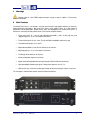
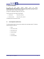
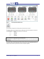
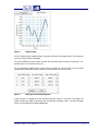
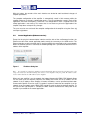
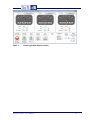
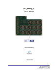
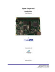
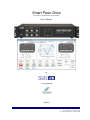
Smart Piezo Drive
Programmable & Autoinstrumented 200 Volt amplifier
User’s Manual
by
In association with
July 2012
1040, avenue Belvédère, suite 215
Québec (Québec) G1S 3G3 Canada
Tél.: (418) 686-0993 Fax: (418) 686-2043
1
WARNINGS _________________________________________________ 4
2
MAIN FEATURES ____________________________________________ 4
3
TECHNICAL DATA ___________________________________________ 4
4
SOFTWARE INSTALLATION ___________________________________ 6
4.1
Control Application (USB version) ________________________________________________ 6
4.2
Control Application (Ethernet version) ____________________________________________ 10
Smart Piezo Drive - User’s Manual
3
1
Warnings
Voltages at the X, Y and Z BNC output connectors can go as high as +-200 VDC. This presents
a risk of electrocution.
2
Main Features
The Smart Piezo Drive is a 6-channels, very low noise and drift, high-voltage amplifier for ScanningProbe Microscopy applications. With three main inputs, three auxiliary inputs an a wide range of
adjustments for the parameters (output offsets, gains and bandwidths), the Smart Piezo Drive is a
feature-rich, extremely versatile product. Here is the list of the amplifier features:
•
Three main inputs (X, Y and Z) with adjustable bandwidth (1 kHz, 10 kHz, 50 kHz) and
adjustable gain (x1, x2, x5, x10, x20) on all channels.
•
Three auxiliary inputs (X-aux, Y-aux, Z-aux) with 50 kHz bandwidth and fixed x1 gain.
•
Three differential outputs (X, Y and Z).
•
Adjustable bandwidth (1 kHz, 10 kHz, 50 kHz) on all channels.
•
Adjustable gain (x1, x2, x5, x10, x20) on all channels.
•
Full-Range offset control on all channels.
•
Auxiliary modulation input on all channels
•
Digital control of bandwidth offset and gain through USB and Ethernet connections.
•
High-Speed digital monitoring of signals. Allows peak capture as fast as 7 µs.
•
USB version only: 3-channels oscilloscope function to observe the outputs signals in real time.
The next figures show the front and the rear of the Smart Piezo Driver:
Smart Piezo Drive - User’s Manual
4
Technical Data
Analog Input Channels (scanning)
Main Inputs (X,Y and Z)
Input Impedance
Coupling
Input Connectors
Bandwidth
Gain
Analog Input Channels (auxiliary)
Auxiliary Inputs (X,Y and Z)
Input Resistance
Coupling
Input Connectors
Bandwidth
Gain
Offset (software controlled)
Software Adjustable Offset (X,Y and Z)
Bandwidth
Slew Rate Limit
High Voltage Outputs
Output Channels (X+,X-,Y+,Y-,Z+ and Z-)
Maximum Current
Maximum Capacitive Load
Output Connectors
Signal Quality
Output Noise (gain x1 and 50kHz)
Output Noise Spectral Density (gain x1 and
50kHz)
Output Noise (gain x20 and 50kHz)
Output Noise Spectral Density (gain x20 and
50kHz)
Maximum Slew Rate (10 nF load)
Output Thermal Drift
Self-Instrumentation
Max History Length
Max Scope Function Depth
Scope Function Sampling Rate
Dimensions
Chassis
Weight
Electrical Supply
External Power Pack
Power Consumption (quiescent)
Smart Piezo Drive - User’s Manual
+-10V
10 kΩ
DC
BNC
Software adjustable: 1kHz, 10 kHz and 50 kHz
Software adjustable: x1, x2, x5, x10 and x20
+-10V
100 kΩ
DC
BNC
50kHz
x1
+-200V
30 Hz
Software adjustable: 1 V/s to 10V/s or bypass
+-200V
15 mA
Tested up to 1 µF
3x Hirose RM15 series circular connectors
70 µVrms
3 µVrms/sqrtHz (@ 10 Hz), 1.3 µVrms/sqrtHz (@ 100 Hz) and
500 nVrms/sqrtHz (@ 1 kHz)
130 µVrms
4.5 µVrms/sqrtHz (@ 10 Hz), 2 µVrms/sqrtHz (@ 100 Hz) and 1
µVrms/sqrtHz (@ 1 kHz)
1500 V/ms
2 ppm-FSR/degC (max)
Unlimited
60 s
150 kHz
18’’x12’’x5’’
5 kg
Input 120VAC, Output 24VDC 5 A (included)
14W
5
3 Software Installation
To
install
the
high
voltage
amplifier
software,
launch
the
installer
SoftdB_Smart_Piezo_Drive_V130.exe and follow the on-screen instructions. At the end of the
installation procedure, the SR3Pro USB driver is automatically installed if it was not already. The highvoltage amplifier software is located in the following folder:
C:\Program Files (x86)\SoftdB_ SoftdB_Smart_Piezo_Drive\
There are two versions of the amplifier control software:
1) USB version:
Smart_Piezo_Drive.exe
2) Ethernet version:
Smart_Piezo_Drive _Net.exe
The following sections describe both versions.
3.1
Control Application (USB version)
The control application allows the setup and the monitoring of the high-voltage amplifier. The following
control panel provides control over:
•
Offsets
•
Offset slew rate limiter
•
Drift correction setup
•
Channel sensitivity
•
Channel gains
•
Channel bandwidths
Smart Piezo Drive - User’s Manual
6
Figure 1
Control application (USB version)
Use this button to change the sensitivity and the unit name for each channel.
The output positions are presented in the user define units. All values displayed or entered can
be appended with a 1-letter suffix that indicates the scaling factor:
• m
for mili
• u
for micro
• n
for nano
• p
for pico
• f
for femto
Note: The absence of suffix implies that the scaling factor is 1. The user must be careful to use the
proper suffix when it is required at the end of the entered values.
Alternately the user can append an exponent in the form exx or Exx, e-xx or E-xx at the end of the
entered value.
The instantaneous, peak-minimum and peak-maximum outputs for all the output channels are
monitored in real-time by the application. For each channel, the Output History tab presents the
history for the pk-minimum, pk-maximum and the instantaneous positions:
Smart Piezo Drive - User’s Manual
7
Figure 2
Output History
Use the Output History Length control to change the amount of recorded history. The history can
be reset using the Reset Histo button.
The Offset Slew-Rate Limiter control specifies the maximum rate of change of the offset in V/s,
and the value is the same for all the axes.
The red emergency button can be used to return all offsets to a preset value. Use the control
Setup under the red button to define the preset and the offset limits for each axis:
Figure 3
Offset preset and limits dialog box
A drift correction is applied when the Activate Correction control is set to ON. The outputs are
slowly ramped up or down according to the specified drift correction values. The drift correction
values are specified by the following dialog box:
Smart Piezo Drive - User’s Manual
8
Figure 4
Drift correction dialog box
Each drift correction value is scaled by the Sensitivity value that is set for the corresponding
channel.
With the USB version of the interface, a oscilloscope function can be used to monitor the output
signals in real time. The sampling frequency is 75 kHz and the memory length is 60 s. The next
figure presents the oscilloscope window (launched by the Scope button of the main interface):
Figure 5
Oscilloscope window
The user can pause the acquisition at anytime and use the zoom functionalities on the time
signals. The oscilloscope is stopped when the function window is closed.
Smart Piezo Drive - User’s Manual
9
With this button, the controls of the main interface are locked to avoid accidental changes of
amplifier parameters.
The complete configuration of the amplifier is automatically saved in flash memory within the
amplifier whenever a change in configuration occurs. The last configuration saved in flash will be
applied the next time the amplifier is turned-on. The configuration in flash is applied even if the
control application is not running. This means that it is not necessary to run the application if the
amplifier setup does not require any changes.
The user can also save and recall the complete configuration of the amplifier using the Save .cfg
and Open .cfg buttons.
3.2
Control Application (Ethernet version)
Except for the physical communication interface and the lack of the oscilloscope function, the
Ethernet version of the control application works exactly the same way as the USB version. The
Ethernet interface requires that both the PC and the amplifier be connected on the same network.
When the Ethernet version is launched, the following dialog box is presented to determine the IP
address of the amplifier:
Figure 6
IP address dialog box
Note: It is possible to control the amplifier remotely through the Internet. In order to do that you need to
setup your router for Port-Forwarding and connect to the amplifier using the public IP address of the
router, rather than the local IP address of the amplifier.
When only one amplifier is on the network, the button Connect with SRM3_PRO Network Name
can be used since the amplifier publishes the SRM3_PRO name and its IP address on the
network. If the IP address of the amplifier is known, the address can be specified and the button
Connect with Specific IP can be used. This option is required if more than one amplifier is on the
network since the network name SRM3_PRO cannot be used to select the desired amplifier. To
be sure that the right amplifier is selected, the MAC number marked on the front panel of the
amplifier is presented on the control application:
Smart Piezo Drive - User’s Manual
10
Figure 7
Control application (Ethernet version)
Smart Piezo Drive - User’s Manual
11