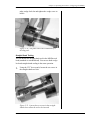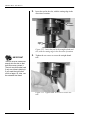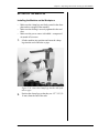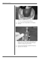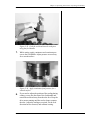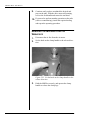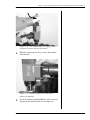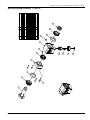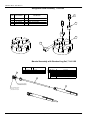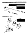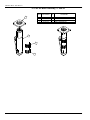
1
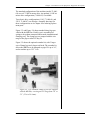
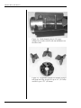
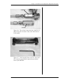
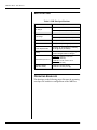
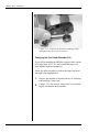
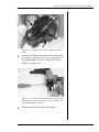
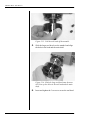
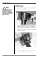
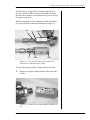
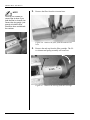
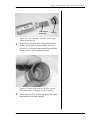
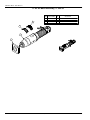
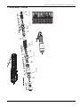
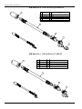
MB Plus Boiler Tube Beveler
User’s Manual
E.H. Wachs
600 Knightsbridge Parkway
Lincolnshire, IL 60069
www.ehwachs.com
E.H. Wachs Part No. 71-MAN-03
Rev. B, August 2013
Revision History:
Original December 2009
Rev. A
January 2013
Copyright © 2013 E.H. Wachs. All rights reserved.
This manual may not be reproduced in whole or in part
without the written consent of E.H. Wachs.
Table of Contents
Table of Contents
Chapter 1: About This Manual . . . . . . . . . . . . . . . . . . . . . . . . . . . . . . . . . . . . . . . . . . . . . . . . . 1
Purpose of This Manual . . . . . . . . . . . . . . . . . . . . . . . . . . . . . . . . . . . . . . . . . . . . . . . . . . . . . . . . . 1
How to Use The Manual . . . . . . . . . . . . . . . . . . . . . . . . . . . . . . . . . . . . . . . . . . . . . . . . . . . . . . . . 2
Symbols and Warnings . . . . . . . . . . . . . . . . . . . . . . . . . . . . . . . . . . . . . . . . . . . . . . . . . . . . . . . . . 2
Manual Updates and Revision Tracking . . . . . . . . . . . . . . . . . . . . . . . . . . . . . . . . . . . . . . . . . . . . 3
Chapter 2: Safety . . . . . . . . . . . . . . . . . . . . . . . . . . . . . . . . . . . . . . . . . . . . . . . . . . . . . . . . . . . . . 5
Operator Safety . . . . . . . . . . . . . . . . . . . . . . . . . . . . . . . . . . . . . . . . . . . . . . . . . . . . . . . . . . . . . . . 5
Safety Symbols . . . . . . . . . . . . . . . . . . . . . . . . . . . . . . . . . . . . . . . . . . . . . . . . . . . . . . . . . . . . 6
Protective Equipment Requirements . . . . . . . . . . . . . . . . . . . . . . . . . . . . . . . . . . . . . . . . . . . . 7
Safety Labels . . . . . . . . . . . . . . . . . . . . . . . . . . . . . . . . . . . . . . . . . . . . . . . . . . . . . . . . . . . . . . . . . 7
Chapter 3: Introduction to the Equipment . . . . . . . . . . . . . . . . . . . . . . . . . . . . . . . . . . . . . . . . 9
Equipment Description . . . . . . . . . . . . . . . . . . . . . . . . . . . . . . . . . . . . . . . . . . . . . . . . . . . . . . . . . 9
Specifications . . . . . . . . . . . . . . . . . . . . . . . . . . . . . . . . . . . . . . . . . . . . . . . . . . . . . . . . . . . . . . . . 14
Operating Envelope . . . . . . . . . . . . . . . . . . . . . . . . . . . . . . . . . . . . . . . . . . . . . . . . . . . . . . . . . . . 14
Chapter 4: Assembly, Disassembly, and Storage . . . . . . . . . . . . . . . . . . . . . . . . . . . . . . . . . . 19
Storage Checklist . . . . . . . . . . . . . . . . . . . . . . . . . . . . . . . . . . . . . . . . . . . . . . . . . . . . . . . . . . . . . 20
Chapter 5: Operating Instructions . . . . . . . . . . . . . . . . . . . . . . . . . . . . . . . . . . . . . . . . . . . . . . 21
Configuring the MB Plus . . . . . . . . . . . . . . . . . . . . . . . . . . . . . . . . . . . . . . . . . . . . . . . . . . . . . . . 21
Selecting and Installing Clamp Legs . . . . . . . . . . . . . . . . . . . . . . . . . . . . . . . . . . . . . . . . . . . 21
Changing the Tool Head (Extender Kit) . . . . . . . . . . . . . . . . . . . . . . . . . . . . . . . . . . . . . . . . 28
Installing the Tooling . . . . . . . . . . . . . . . . . . . . . . . . . . . . . . . . . . . . . . . . . . . . . . . . . . . . . . . 31
Wedge-Lock Tooling . . . . . . . . . . . . . . . . . . . . . . . . . . . . . . . . . . . . . . . . . . . . . . . . . . . . 32
Straight-Shank Tooling . . . . . . . . . . . . . . . . . . . . . . . . . . . . . . . . . . . . . . . . . . . . . . . . . . 33
Setting Up The MB Plus . . . . . . . . . . . . . . . . . . . . . . . . . . . . . . . . . . . . . . . . . . . . . . . . . . . . . . . 35
Installing the Machine on the Workpiece . . . . . . . . . . . . . . . . . . . . . . . . . . . . . . . . . . . . . . . 35
Adjusting the Tooling . . . . . . . . . . . . . . . . . . . . . . . . . . . . . . . . . . . . . . . . . . . . . . . . . . . . . . 37
Operating the Machine . . . . . . . . . . . . . . . . . . . . . . . . . . . . . . . . . . . . . . . . . . . . . . . . . . . . . . . . . 39
Removing the Machine from the Workpiece . . . . . . . . . . . . . . . . . . . . . . . . . . . . . . . . . . . . . . . . 42
Chapter 6: Routine Maintenance . . . . . . . . . . . . . . . . . . . . . . . . . . . . . . . . . . . . . . . . . . . . . . . 45
Machine Lubrication . . . . . . . . . . . . . . . . . . . . . . . . . . . . . . . . . . . . . . . . . . . . . . . . . . . . . . . . . . 45
Air Motor Lubrication . . . . . . . . . . . . . . . . . . . . . . . . . . . . . . . . . . . . . . . . . . . . . . . . . . . . . . . . . 45
Replace Air Line Filter . . . . . . . . . . . . . . . . . . . . . . . . . . . . . . . . . . . . . . . . . . . . . . . . . . . . . . . . 46
Chapter 7: Service and Repair . . . . . . . . . . . . . . . . . . . . . . . . . . . . . . . . . . . . . . . . . . . . . . . . . 53
Removing and Installing the Drive Motor . . . . . . . . . . . . . . . . . . . . . . . . . . . . . . . . . . . . . . . . . . 53
E.H. Wachs
Part No. 71-MAN-03, Rev. B
i
MB Plus Boiler Tube Beveler
Air Motor Service . . . . . . . . . . . . . . . . . . . . . . . . . . . . . . . . . . . . . . . . . . . . . . . . . . . . . . . . . . . . 55
0.75 HP Configuration (71-000-04) . . . . . . . . . . . . . . . . . . . . . . . . . . . . . . . . . . . . . . . . . . . 55
1.1 HP Configuration (71-000-05) . . . . . . . . . . . . . . . . . . . . . . . . . . . . . . . . . . . . . . . . . . . . 55
Chapter 8: Parts Lists and Drawings . . . . . . . . . . . . . . . . . . . . . . . . . . . . . . . . . . . . . . . . . . .
Assembly Drawings . . . . . . . . . . . . . . . . . . . . . . . . . . . . . . . . . . . . . . . . . . . . . . . . . . . . . . . . . . .
MB Plus, 0.75 HP Air Drive Configuration . . . . . . . . . . . . . . . . . . . . . . . . . . . . . . . . . . . . .
MB Plus, 1.1 HP Air Drive Configuration . . . . . . . . . . . . . . . . . . . . . . . . . . . . . . . . . . . . . .
Drawbar Ratchet Assembly, 71-402-01 . . . . . . . . . . . . . . . . . . . . . . . . . . . . . . . . . . . . . . . .
Feed Housing Assembly, 71-407-00 . . . . . . . . . . . . . . . . . . . . . . . . . . . . . . . . . . . . . . . . . . .
Bearing Housing Assembly, 71-408-00 . . . . . . . . . . . . . . . . . . . . . . . . . . . . . . . . . . . . . . . .
Wedgelock Head Assembly, 71-409-00 . . . . . . . . . . . . . . . . . . . . . . . . . . . . . . . . . . . . . . . .
Mandrel Assembly with Standard Leg Set, 71-410-00 . . . . . . . . . . . . . . . . . . . . . . . . . . . . .
Mandrel Assembly with Extended Leg Set, 71-410-01 . . . . . . . . . . . . . . . . . . . . . . . . . . . .
Extended Range (3.0”) Kit, 71-401-00 . . . . . . . . . . . . . . . . . . . . . . . . . . . . . . . . . . . . . . . . .
0.75 HP Air Motor Assembly, 71-406-00 . . . . . . . . . . . . . . . . . . . . . . . . . . . . . . . . . . . . . .
0.75 HP Air Motor, 71-026-00 . . . . . . . . . . . . . . . . . . . . . . . . . . . . . . . . . . . . . . . . . . . . . . .
1.1 HP Air Motor Assembly, 71-404-00 . . . . . . . . . . . . . . . . . . . . . . . . . . . . . . . . . . . . . . .
1.1 HP Air Motor, 71-060-00 . . . . . . . . . . . . . . . . . . . . . . . . . . . . . . . . . . . . . . . . . . . . . . . .
ATM Hose (for 0.75 HP Air Drive), 80-4202-00 . . . . . . . . . . . . . . . . . . . . . . . . . . . . . . . . .
ATM Hose (for 1.1 HP Air Drive), 71-405-00 . . . . . . . . . . . . . . . . . . . . . . . . . . . . . . . . . . .
110 V Electric Drive MB Plus (Obsolete), 71-000-06 . . . . . . . . . . . . . . . . . . . . . . . . . . . . .
220 V Electric Drive MB Plus (Obsolete), 71-000-07 . . . . . . . . . . . . . . . . . . . . . . . . . . . . .
57
57
58
59
60
60
61
62
62
63
63
64
65
66
67
68
68
69
70
Chapter 9: Accessories and Spare Parts . . . . . . . . . . . . . . . . . . . . . . . . . . . . . . . . . . . . . . . . . 71
Tooling . . . . . . . . . . . . . . . . . . . . . . . . . . . . . . . . . . . . . . . . . . . . . . . . . . . . . . . . . . . . . . . . . . . . . 71
Accessories . . . . . . . . . . . . . . . . . . . . . . . . . . . . . . . . . . . . . . . . . . . . . . . . . . . . . . . . . . . . . . . . . 72
Chapter 10: Ordering Information . . . . . . . . . . . . . . . . . . . . . . . . . . . . . . . . . . . . . . . . . . . . .
Ordering Replacement Parts . . . . . . . . . . . . . . . . . . . . . . . . . . . . . . . . . . . . . . . . . . . . . . . . . . . .
Repair Information . . . . . . . . . . . . . . . . . . . . . . . . . . . . . . . . . . . . . . . . . . . . . . . . . . . . . . . . . . .
Warranty Information . . . . . . . . . . . . . . . . . . . . . . . . . . . . . . . . . . . . . . . . . . . . . . . . . . . . . . . . .
Return Goods Address . . . . . . . . . . . . . . . . . . . . . . . . . . . . . . . . . . . . . . . . . . . . . . . . . . . . . . . . .
ii
Part No. 71-MAN-03, Rev. B
73
73
73
74
74
E.H. Wachs
Chapter 1, About This Manual
Chapter 1
About This Manual
PURPOSE OF THIS MANUAL
This manual explains how to operate and maintain the MB
Plus boiler tube beveler. It includes instructions for set-up,
operation, and maintenance. It also contains parts lists, diagrams, and service information to help you order replacement parts and perform user-serviceable repairs.
In This Chapter
PURPOSE OF THIS MANUAL
HOW TO USE THE MANUAL
SYMBOLS AND WARNINGS
MANUAL UPDATES AND
REVISION TRACKING
Before operating the MB Plus, you should read through this
manual and become familiar with all instructions. At a minimum, make sure you read and understand the following
chapters:
•
•
•
•
•
Chapter 1, About This Manual
Chapter 2, Safety
Chapter 3, Introduction to the Equipment
Chapter 5, Operating Instructions
Chapter 9, Accessories
If you will be performing service or repairs, make sure you
read and understand these chapters:
•
•
•
•
Chapter 1, About This Manual
Chapter 4, Assembly and Disassembly
Chapter 6, Routine Maintenance
Chapter 7, Service and Repair.
You will also want to refer to Chapter 8, Parts Lists and
Drawings.
E.H. Wachs
Part No. 71-MAN-03, Rev. B
1
MB Plus Boiler Tube Beveler
HOW TO USE THE MANUAL
Throughout this manual, refer
to this column for warnings,
cautions, and notices with
supplementary information.
This manual is organized to help you quickly find the information you need. Each chapter describes a specific topic on
using or maintaining your equipment.
Each page is designed with two columns. This large column
on the inside of the page contains instructions and illustrations. Use these instructions to operate and maintain the
equipment.
The narrower column on the outside contains additional
information such as warnings, special notes, and definitions.
Refer to it for safety notes and other information.
SYMBOLS AND WARNINGS
The following symbols are used throughout this manual to
indicate special notes and warnings. They appear in the outside column of the page, next to the section they refer to.
Make sure you understand what each symbol means, and
follow all instructions for cautions and warnings.
WARNING
A WARNING alert with the
safety alert symbol indicates
a potentially hazardous situation that could result in serious injury or death.
This is the safety alert symbol. It is used
to alert you to potential personal injury
hazards. Obey all safety messages that
follow this symbol to avoid possible
injury or death.
CAUTION
A CAUTION alert with the
safety alert symbol indicates
a potentially hazardous situation that could result in
minor or moderate injury.
2
Part No. 71-MAN-03, Rev. B
E.H. Wachs
Chapter 1, About This Manual: Manual Updates and Revision Tracking
This is the equipment damage alert
symbol. It is used to alert you to potential equipment damage situations.
Obey all messages that follow this symbol to avoid damaging the equipment or
workpiece on which it is operating.
CAUTION
A CAUTION alert with the
damage alert symbol indicates a situation that will
result in damage to the
equipment.
IMPORTANT
An IMPORTANT alert with
the damage alert symbol indicates a situation that may
result in damage to the
equipment.
NOTE
NOTE
This symbol indicates a user note. Notes
provide additional information to supplement the instructions, or tips for easier
operation.
A NOTE provides supplementary information or operating tips.
MANUAL UPDATES AND REVISION TRACKING
Occasionally, we will update manuals with improved operation or maintenance procedures, or with corrections if necessary. When a manual is revised, we will update the
revision history on the title page.
You may have factory service or upgrades performed on the
equipment. If this service changes any technical data or
operation and maintenance procedures, we will include a
revised manual when we return the equipment to you.
E.H. Wachs
Part No. 71-MAN-03, Rev. B
Current versions of E.H.
Wachs Company manuals
are also available in PDF format. You can request an
electronic copy of this manual
by emailing customer service
at [email protected].
3
MB Plus Boiler Tube Beveler
4
Part No. 71-MAN-03, Rev. B
E.H. Wachs
Chapter 2, Safety
Chapter 2
Safety
In This Chapter
The E.H. Wachs Company takes great pride in designing
and manufacturing safe, high-quality products. We make
user safety a top priority in the design of all our products.
OPERATOR SAFETY
SAFETY LABELS
Read this chapter carefully before operating the MB Plus. It
contains important safety instructions and recommendations.
OPERATOR SAFETY
Follow these guidelines for safe operation of the equipment.
•
•
•
•
READ THE OPERATING MANUAL. Make sure
you understand all setup and operating instructions
before you begin.
INSPECT MACHINE AND ACCESSORIES.
Before starting the machine, look for loose bolts or
nuts, leaking lubricant, rusted components, and any
other physical conditions that may affect operation.
Properly maintaining the machine can greatly decrease
the chances for injury.
ALWAYS READ PLACARDS AND LABELS. Make
sure all placards, labels, and stickers are clearly legible
and in good condition. You can purchase replacement
labels from E.H. Wachs Company.
KEEP CLEAR OF MOVING PARTS. Keep hands,
arms, and fingers clear of all rotating or moving parts.
E.H. Wachs
Part No. 71-MAN-03, Rev. B
Look for this symbol throughout the
manual. It indicates
a personal injury
hazard.
5
MB Plus Boiler Tube Beveler
•
•
Always turn machine off before doing any adjustments
or service.
SECURE LOOSE CLOTHING AND JEWELRY.
Secure or remove loose-fitting clothing and jewelry, and
securely bind long hair, to prevent them from getting
caught in moving parts of the machine.
KEEP WORK AREA CLEAR. Keep all clutter and
nonessential materials out of the work area. Only people
directly involved with the work being performed should
have access to the area.
Safety Symbols
This icon is displayed with any safety alert that indicates a
personal injury hazard.
WARNING
This safety alert indicates a potentially hazardous situation
that, if not avoided, could result in death or serious injury.
CAUTION
This safety alert, with the personal injury hazard symbol,
indicates a potentially hazardous situation that, if not
avoided, could result in minor or moderate injury.
6
Part No. 71-MAN-03, Rev. B
E.H. Wachs
Chapter 2, Safety: Safety Labels
Protective Equipment Requirements
WARNING
Always wear impact resistant eye protection while operating or working near
this equipment.
For additional information on eye and face protection, refer
to Federal OSHA regulations, 29 Code of Federal Regulations, Section 1910.133., Eye and Face Protection and
American National Standards Institute, ANSI Z87.1, Occupational and Educational Eye and Face Protection. Z87.1 is
available from the American National Standards Institute,
Inc., 1430 Broadway, New York, NY 10018.
CAUTION
Personal hearing protection is recommended when operating or working near
this tool.
Hearing protectors are required in high noise areas, 85 dBA
or greater. The operation of other tools and equipment in the
area, reflective surfaces, process noises, and resonant structures can increase the noise level in the area. For additional
information on hearing protection, refer to Federal OSHA
regulations, 29 Code of Federal Regulations, Section
1910.95, Occupational Noise Exposure and ANSI S12.6
Hearing Protectors.
SAFETY LABELS
The safety label in Figure 2-1 is on the MB Plus machine.
The safety label on the air motor is shown in Figure 2-2. If
any label is removed or damaged, order a replacement. See
Chapter 10 for ordering information.
E.H. Wachs
Part No. 71-MAN-03, Rev. B
7
MB Plus Boiler Tube Beveler
Figure 2-1. This Warning label (part number 71-06200) is on the MB Plus machine.
Figure 2-2. The safety Caution label (part number 90401-03) is on the air motor.
Figure 2-3. The air pressure Caution label (part number 90-401-02) is on the air motor.
8
Part No. 71-MAN-03, Rev. B
E.H. Wachs
Chapter 3, Introduction to the Equipment
Chapter 3
Introduction to the
Equipment
In This Chapter
The MB Plus is an I.D. (inside diameter) mounted beveling
machine for prepping boiler tubes. The MB Plus is an
improved version of the Wachs MB boiler tube beveler; it
features larger bearings and hardened components for better durability, while maintaining the high performance, convenient setup, and easy operation of the full line of Wachs
beveling machines.
EQUIPMENT DESCRIPTION
SPECIFICATIONS
OPERATING ENVELOPE
EQUIPMENT DESCRIPTION
The MB Plus features the following components:
•
•
•
•
•
•
a machine body with gearbox, feed mechanism, and
drive adapter
a self-centering mandrel with drawbar and ratcheting
clamp handle
multiple clamp leg sets for I.D. mounting on the full
range of tube sizes
a rotating tool head
a ratcheting feed handle
0.75 or 1.1 HP pneumatic drive motor.
Figure 3-1 illustrates the components of the MB Plus.
Figure 3-2 shows the tool head and tool mounting slots.
E.H. Wachs
Part No. 71-MAN-03, Rev. B
9
MB Plus Boiler Tube Beveler
Drawbar
retaining collar
Drawbar
Clamp
handle
Machine body
Tool head
Feed
handle
Mandrel
Air motor
trigger
Clamping legs
Air motor
(1.2 HP)
Figure 3-1. The photo shows the MB Plus configuration with the 1.1 HP motor (71-000-05).
Wedge-lock
tool slots (2)
Straight-shank
tool slot (1)
Figure 3-2. The photo shows the tool mounting slots
on the standard tool head.
10
Part No. 71-MAN-03, Rev. B
E.H. Wachs
Chapter 3, Introduction to the Equipment: Equipment Description
The standard configuration of the machine (model 71-00004) uses a 0.75 HP air motor drive. An optional 1.1 HP air
motor drive configuration (71-000-05) is available.
Two electric drive configurations (110 V, 71-000-06; and
220 V, 71-000-07) are obsolete. Assembly drawings for
these configurations are in Chapter 8 for ordering replacement parts.
Figure 3-3 and Figure 3-4 show standard clamp legs provided with the MB Plus. Each leg set is assembled on
springs to keep them connected and to make installation and
clamping easy. The clamp legs are stamped with the size
range of the pipe or tube I.D. they fit.
Figure 3-5 shows the optional extender kit, with 3 larger
sets of clamp legs and a larger tool head. The extender kit
allows the MB Plus to be mounted on pipe I.D. up to 3.0”,
and to machine up to 3.25” O.D.
Figure 3-3. Five standard clamp leg sets are supplied
with the MB Plus, covering an I.D. range from 1.0” to
2.3” (25.4 to 58.4 mm).
E.H. Wachs
Part No. 71-MAN-03, Rev. B
11
MB Plus Boiler Tube Beveler
Figure 3-4. Each clamp leg has its I.D. range
stamped on it (inches on one side and millimeters on
the other side).
Figure 3-5. An optional extender kit includes a larger
tool head and 3 leg sets for I.D. up to 3.0” (76.2 mm)
and O.D. up to 3.25” (82.6 mm).
12
Part No. 71-MAN-03, Rev. B
E.H. Wachs
Chapter 3, Introduction to the Equipment: Equipment Description
Lubricator
Air filter
Figure 3-6. The air hose connection has a built-in air
filter to keep the air motor clean, and a lubricator to
oil the motor.
Figure 3-7. A hex wrench cluster and 1/8” short-arm
hex wrench are provided for operation and maintenance of the MB Plus.
E.H. Wachs
Part No. 71-MAN-03, Rev. B
13
MB Plus Boiler Tube Beveler
SPECIFICATIONS
Table 1: MB Plus Specifications
Feature
Specification
Standard: 1.00” to 2.30” (25.4 to 58.4 mm)
I.D. Range
Extended: up to 3.0” (76.2 mm)
Standard: 1.25” to 2.50” (31.8 to 63.5 mm)
O.D. Range
Extended: up to 3.25” (82.6 mm)
Feed Rate
0.111” (2.8 mm) per handle revolution
Max. Wall Thickness
0.63” (16.0 mm)—tooling dependent
Power Requirements
Air supply: 31 cfm @ 90 psi (71-000-04);
35 cfm @ 90 psi (71-000-05)
Tooling
Standard Wachs beveler tooling; wedgelock and straight-shank tool designs
Dimensions (H x W x L)
71-000-04: 10.28" X 2.5" X 15.5"
(261 x 64 x 394 mm)
71-000-05: 14.25" X 2.5" X 15.5"
(362 x 64 x 394 mm)
Operating Weight
(with drive motor)
71-000-04: 18.6 lbs (8.4 kg)
71-000-05: 23.2 lbs (10.5 kg)
OPERATING ENVELOPE
The drawings on the following pages illustrate the operating
envelopes for both drive configurations of the MB Plus.
14
Part No. 71-MAN-03, Rev. B
E.H. Wachs
Chapter 3, Introduction to the Equipment: Operating Envelope
15.50 MAX
393.7
2.50
63.5
2.50
63.5
3.48
88.4
.62
15.7
.83
21
70-701-00
FACING TOOL
1.62
41
MAX
TRAVEL
10.28
261
2.60
65.9
Operating envelope for standard (0.75 HP) air drive configuration (71-000-04).
E.H. Wachs
Part No. 71-MAN-03, Rev. B
15
MB Plus Boiler Tube Beveler
15.50
393.7
2.50
63.5
2.50
63.5
3.48
88.4
.62
15.7
.83
21
70-701-00
FACING TOOL
1.62
41
MAX
TRAVEL
14.25
362
1.33
33.7
Operating envelope for 1.1 HP air drive configuration (71-000-05).
16
Part No. 71-MAN-03, Rev. B
E.H. Wachs
Chapter 3, Introduction to the Equipment: Operating Envelope
2.74 MAX
69.6
LEGS SHOWN FULLY EXTENDED
SCALE: 1:1
1.25
31.8
1.00 MIN
25.4
LEGS SHOWN FULLY RETRACTED
SCALE:1:1
.62
15.7
Operating envelope for standard leg sets (all configurations).
E.H. Wachs
Part No. 71-MAN-03, Rev. B
17
MB Plus Boiler Tube Beveler
18
Part No. 71-MAN-03, Rev. B
E.H. Wachs
Chapter 4, Assembly, Disassembly, and Storage
Chapter 4
Assembly, Disassembly,
and Storage
In This Chapter
The MB Plus is shipped fully assembled and ready for use.
The only assembly steps typically required are installing
the clamping legs and tooling. These procedures are
described in the operating instructions in Chapter 5.
STORAGE CHECKLIST
The machine is shipped and stored in a durable, customized
storage case, as shown in Figure 4-1. The case includes
compartments for clamping legs, hand tools, tooling, and
accessories.
NOTE
You do not need to remove
the drive motor for storing the
machine.
Figure 4-1. Store the MB Plus and its accessories in
the case provided. Compartments are provided for all
standard and optional components.
E.H. Wachs
Part No. 71-MAN-03, Rev. B
19
MB Plus Boiler Tube Beveler
Keep the machine stored in its case when not using it.
Always use the case when shipping the MB Plus. The case
includes a padlock slot for secure storage and shipping.
Figure 4-2. Press the latches down securely to snap
them closed. If necessary, you can use a padlock to
secure the machine in its case.
STORAGE CHECKLIST
Before storing the MB Plus, perform the following maintenance steps. If you are using the machine in an especially
dirty or corrosive environment, perform these steps frequently.
•
•
•
•
•
•
•
20
Clean the machine by wiping off dirt, debris, and accumulated oil or grease.
Put oil in the air motor oiler, and operate the motor for a
few seconds to lubricate its internal components.
Lubricate the machine according to the instructions in
Chapter 6.
Spray or wipe a light coating of anti-corrosion lubricant
on non-finished, non-painted surfaces.
Put the machine in its storage case, with all components
stored in their compartments.
If possible, keep the storage case indoors and away from
moisture.
If you will be storing the machine longer than 30 days,
put desiccant packets in the case to prevent corrosion.
Part No. 71-MAN-03, Rev. B
E.H. Wachs
Chapter 5, Operating Instructions
Chapter 5
Operating Instructions
In This Chapter
CONFIGURING THE MB PLUS
CONFIGURING THE MB PLUS
Before you install the MB Plus on the workpiece, set it up
with the required clamp legs (and tool head, if you have the
optional extender kit).
SETTING UP THE MB PLUS
OPERATING THE MACHINE
REMOVING THE MACHINE
FROM THE WORKPIECE
Selecting and Installing Clamp Legs
There are 5 standard sets of clamp legs provided with the
MB Plus. Table 1 lists the clamp leg sets and their I.D.
ranges.
Table 1: Standard Clamp Leg Sets
Part No.
Minimum I.D.
Maximum I. D.
Recommended
Tube I.D. Range
71-400-01
1.00” (25.4 mm)
1.32” (33.5 mm)
1.00”-1.28”
(25.4-32.6 mm)
71-400-02
1.25” (31.2 mm)
1.56” (39.6 mm)
1.29”-1.52”
(32.7-38.7 mm)
71-400-03
1.49” (37.8 mm)
1.80” (45.7 mm)
1.53”-1.76”
(38.8-44.8 mm)
71-400-04
1.73” (43.9 mm)
2.05” (52.1 mm)
1.77”-2.01”
44.9-51.0 mm)
71-400-05
1.98” (50.3 mm)
2.30” (58.4 mm)
2.02”-2.30”
(51.1-58.4 mm)
The optional extender kit has 3 additional sets of clamp
legs. Table 2 describes the extender kit clamp legs.
E.H. Wachs
Part No. 71-MAN-03, Rev. B
21
MB Plus Boiler Tube Beveler
Table 2: Extender Kit Clamp Leg Sets
Part No.
Minimum I.D.
Maximum I. D.
Recommended
Tube I.D. Range
71-400-06
2.22” (56.4 mm)
2.55” (64.8 mm)
2.26”-2.51”
(57.4-63.9 mm)
71-400-07
2.47” (62.7 mm)
2.79” (70.9 mm)
2.52”-2.75”
(64.0-70.0 mm)
71-400-08
2.72” (69.1 mm)
3.04” (77.2 mm)
2.76”-3.04”
(70.1-77.2 mm)
The following procedure describes how to remove the
drawbar from the MB Plus and install the clamp legs.
1. Measure the I.D. of the pipe or tube you are machining.
NOTE
Refer to the “Recommended
Tube I.D. Range” column for
pipes or tubes that are in the
“overlap” range between
clamp leg sets.
2. Using the tables above, select the clamp leg set that
fits the I.D. of the pipe or tube.
3. Using a 3/32” hex wrench, loosen the screw in the
drawbar retainer collar. Unscrew the collar to remove
it from the drawbar.
Set screw
Figure 5-1. Loosen the set screw in the drawbar
retaining collar, then turn the collar off the end of the
drawbar.
4. Press the ratchet knob on the clamping ratchet to set
the ratchet in the release direction.
22
Part No. 71-MAN-03, Rev. B
E.H. Wachs
Chapter 5, Operating Instructions: Configuring the MB Plus
Figure 5-2. Push the clamp ratchet knob as shown to
operate the ratchet in the “unclamping” direction.
5. Operate the clamping ratchet handle to extend the
drawbar out all the way until you can remove it from
the machine.
Figure 5-3. Pull the drawbar out of the mandrel
6. To remove the clamp legs currently installed, pull the
notches of the legs out of their slots in the drawplate.
Slide the leg assembly down the drawbar to remove it.
E.H. Wachs
Part No. 71-MAN-03, Rev. B
23
MB Plus Boiler Tube Beveler
Figure 5-4. Pull the clamp legs up out of the drawplate to remove them.
7. Slide the new leg assembly up the drawbar, with the
notched ends of the legs first.
Figure 5-5. Slide the new set of clamp legs up the
drawbar, with the notched ends of the legs toward the
drawplate.
8. Pull the legs up over the drawplate to engage the leg
notches and hold the leg assembly in place.
24
Part No. 71-MAN-03, Rev. B
E.H. Wachs
Chapter 5, Operating Instructions: Configuring the MB Plus
Figure 5-6. Lift the ends of the clamp legs onto the
drawplate, and slide the notches into place to secure
the legs.
9. Re-insert the drawbar into the machine through the
mandrel.
Figure 5-7. Re-install the drawbar through the mandrel.
10. Move the ratchet knob on the clamping ratchet to set
the ratchet in the clamping direction.
E.H. Wachs
Part No. 71-MAN-03, Rev. B
25
MB Plus Boiler Tube Beveler
Figure 5-8. Push the knob as shown to set the clamping ratchet to the clamping direction.
11. Push the drawbar into the machine until it stops. Turn
it as shown in Figure 5-9 to thread the drawbar into
the machine.
Figure 5-9. While pushing in on the drawbar, turn it
to thread it into the machine. Screw it all the way in.
12. When the clamp legs reach the end of the mandrel,
turn the drawbar to line the legs up with the slots in the
mandrel.
26
Part No. 71-MAN-03, Rev. B
E.H. Wachs
Chapter 5, Operating Instructions: Configuring the MB Plus
Figure 5-10. Line up the clamp legs with the slots in
the end of the mandrel.
13. Operate the clamping ratchet until the legs are
engaged in the slots. Do not clamp the legs any farther
until you install the machine in the tube.
Figure 5-11. Operate the clamping lever to draw the
clamp legs into the mandrel.
14. Re-install the retaining collar on the end of the drawbar and tighten the set screw to secure it.
E.H. Wachs
Part No. 71-MAN-03, Rev. B
27
MB Plus Boiler Tube Beveler
Figure 5-12. Replace the drawbar retaining collar
and tighten the set screw to secure it.
Changing the Tool Head (Extender Kit)
If you will be installing the MB Plus on pipe or tube with an
O.D. larger than 3.00” (76.2 mm), install the larger tool
head included with the extender kit.
Follow the same procedure to remove the larger tool head
and replace the standard head.
1. Remove the drawbar as described above in “Selecting
and Installing Clamp Legs”.
2. Using a 3/16” hex wrench, remove the 3 screws holding the tool head to the main shaft.
28
Part No. 71-MAN-03, Rev. B
E.H. Wachs
Chapter 5, Operating Instructions: Configuring the MB Plus
Figure 5-13. Remove the 3 screws holding the tool
head.
3. If you need to hold the tool head to keep it from rotating while you loosen the screws, use a screwdriver in
the straight shank tool slot, or clamp the tool head
gently in a soft-jaw vise.
Figure 5-14. To keep the tool head from turning while
loosening the screws, you can insert a screwdriver in
the straight shank tool slot.
4. Pull the tool head off the end of the mandrel.
E.H. Wachs
Part No. 71-MAN-03, Rev. B
29
MB Plus Boiler Tube Beveler
Figure 5-15. Pull the tool head off the mandrel.
5. Slide the larger tool head over the mandrel and align
the holes in the head and the main shaft.
Figure 5-16. Slide the large tool head onto the mandrel. Line up the holes in the tool head and the main
shaft.
6. Insert and tighten the 3 screws to secure the tool head.
30
Part No. 71-MAN-03, Rev. B
E.H. Wachs
Chapter 5, Operating Instructions: Configuring the MB Plus
Figure 5-17. Install and tighten the 3 screws holding
the tool head.
7. Replace the drawbar through the mandrel and install it
according to the instructions in “Selecting and Installing Clamp Legs” above.
Installing the Tooling
It is easiest to install the tooling on the MB Plus before setting up the machine on the workpiece.
There are 2 wedge-lock slots in the tool head. You can
install any combination of bevel, facing, and counterbore
tooling.
There is also a 1/4” straight-shank tool slot in the tool head.
You can install any standard Wachs 1/4” end prep tooling in
this slot.
E.H. Wachs
Part No. 71-MAN-03, Rev. B
31
MB Plus Boiler Tube Beveler
Wedge-Lock Tooling
NOTE
The wedge-lock tooling is
designed so that it can only
be installed in the correct
direction. The etched arrows
in the main shaft show the
direction of rotation.
1. Slide the base of the selected tool beneath the wedge
in the slot. If the tool will not fit, loosen the wedgelock screw using a 3/32” hex wrench.
Direction
of rotation
Tip of wedge
beneath
ridge on
tool shank
Figure 5-18. Slide the tool into the wedge-lock slot on
the tool head. Make sure the tip of the wedge fits up
against the ridge in the side of the tool, as indicated.
2. Using a 3/32” hex wrench, tighten down the wedge to
hold the tool in place.
Figure 5-19. Tighten the wedge screw to secure the
tool.
3. If you are installing a second tool (such as a beveling
tool for a facing/bevel operation), slide it into the
32
Part No. 71-MAN-03, Rev. B
E.H. Wachs
Chapter 5, Operating Instructions: Configuring the MB Plus
other wedge-lock slot and tighten the wedge screw to
hold it.
Figure 5-20. The photo shows the installation of a
beveling tool.
Straight-Shank Tooling
You can install one straight-shank tool in the MB Plus tool
head (standard or extended head). You can use both wedgelock and straight-shank tooling in the same operation.
1. Using the 3/32” hex wrench, loosen the set screws in
the straight-shank tool slot.
Figure 5-21. Loosen the set screws in the straightshank slot to allow the tool to be inserted.
E.H. Wachs
Part No. 71-MAN-03, Rev. B
33
MB Plus Boiler Tube Beveler
2. Insert the tool in the slot, with the cutting edge in the
direction of rotation.
Direction
of rotation
Cutting
edge
Figure 5-22. Insert the tool in the straight-shank tool
slot, with the cutting edge in the direction of rotation.
3. Tighten the set screws to secure the straight-shank
IMPORTANT
tool.
The tool must be inserted far
enough into the slot so that
both set screws contact it.
The tool may shift under load
if only one screw is holding it.
If you need the tool further
out for a larger I.D. tube, use
the extended tool head.
Figure 5-23. Tighten both set screws to secure the
tool.
34
Part No. 71-MAN-03, Rev. B
E.H. Wachs
Chapter 5, Operating Instructions: Setting Up The MB Plus
SETTING UP THE MB PLUS
Installing the Machine on the Workpiece
•
•
•
Make sure the clamp legs are firmly seated in the drawplate and are engaged in the mandrel.
Make sure the tooling is securely tightened in the tool
slots.
Make sure the power source is disabled—compressed
air turned off at source.
1. Lift the machine into position and insert the clamp
legs into the end of the tube or pipe.
Figure 5-24. Insert the clamp legs into the end of the
tube or pipe.
2. Position the clamp legs so that they are 1/2”-3/4” (1219 mm) from the end of the tube.
E.H. Wachs
Part No. 71-MAN-03, Rev. B
35
MB Plus Boiler Tube Beveler
Figure 5-25. Hold the MB Plus in place with the legs
1/2”-3/4” (12-19 mm) inside the tube end.
3. Set the knob on the clamp handle to the clamping
direction.
Figure 5-26. Set the knob on the clamp handle to the
clamping direction. The clamp handle will engage
clockwise to clamp the legs in the tube.
4. Operate the clamp handle to expand the clamp legs
against the I.D. of the tube.
36
Part No. 71-MAN-03, Rev. B
E.H. Wachs
Chapter 5, Operating Instructions: Setting Up The MB Plus
Figure 5-27. Turn the clamp handle to tighten the
clamp legs in the tube.
5. When the clamp legs get snug, check that they are still
1/2”-3/4” (12-19 mm) from the end of the tube.
(Clamping the legs draws them toward the machine,
out of the tube.) If necessary, push the legs farther into
the tube.
6. Operate the clamp handle to securely tighten the legs.
Do not overtighten—firm pressure with one hand is
enough to secure the machine.
Overtightening the clamp
handle can damage or break
the drawbar.
Adjusting the Tooling
You may need to adjust the position of the tools in the tool
slots to align them with the surface of the tube or pipe.
1. Set the knob on the feed handle to the feed direction.
E.H. Wachs
IMPORTANT
Part No. 71-MAN-03, Rev. B
CAUTION
Turn off the air supply at its
source before adjusting the
tooling.
37
MB Plus Boiler Tube Beveler
Figure 5-28. Push the knob on the feed handle to the
feed forward direction. The handle will engage clockwise to feed the tool head toward the tube end.
2. Operate the feed handle to advance the tools close to
the tube/pipe face.
Figure 5-29. Turn the feed handle clockwise to feed
the tool head.
3. Check the radial positions of the tools to make sure
they will contact the full width of the tube/pipe face.
38
Part No. 71-MAN-03, Rev. B
E.H. Wachs
Chapter 5, Operating Instructions: Operating the Machine
Figure 5-30. Check that the tools are positioned so
that they contact the full width of the tube face.
4. If necessary, adjust the tools by loosening the wedge
screw (or the straight-shank set screws), and moving
the tool in or out until it is positioned fully over the
tube/pipe face. Re-tighten the screws.
OPERATING THE MACHINE
1. Connect the compressed air supply line to the drive
motor.
IMPORTANT
2. If using an air drive, turn on the air supply at the
source.
3. Make sure the direction knob on the feed handle is set
to the feed direction.
E.H. Wachs
Part No. 71-MAN-03, Rev. B
Make sure the air motor lubricator has oil before operating
the machine. See “Air Motor
Lubrication” in Chapter 6.
39
MB Plus Boiler Tube Beveler
Figure 5-31. Push the knob on the feed handle to the
feed forward direction. The handle will engage clockwise to feed the tool head.
4. Release the air motor safety lever and squeeze the trigger to start the motor. The tool head will start to rotate.
5. Adjust the rotating speed by squeezing more or less
tightly on the air motor trigger.
Slower
Faster
Figure 5-32. Depress the air motor trigger to start the
machine. Use the trigger to control the rotating speed.
6. While holding the air trigger, operate the feed lever to
feed the tooling into the tube face.
40
Part No. 71-MAN-03, Rev. B
E.H. Wachs
Chapter 5, Operating Instructions: Operating the Machine
Figure 5-33. Feed the tool head into the workpiece
using the feed handle.
7. While cutting, apply continuous and consistent pressure to the feed handle. Adjust pressure as necessary
for a smooth surface.
Figure 5-34. Apply continuous feed pressure for a
smooth surface.
8. If you need to adjust the position of the tooling during
cutting, reverse the direction of the feed handle and
retract the tool head away from the tube face. Keep the
drive motor running until the tool no longer contacts
the tube. Adjust the tooling as required, set the feed
direction back to forward, and continue cutting.
E.H. Wachs
Part No. 71-MAN-03, Rev. B
41
MB Plus Boiler Tube Beveler
9. Continue until you have machined the desired end
prep on the tube. With the drive motor still running,
reverse the feed handle and retract the tool head.
10. If you need to perform another operation on the tube
(such as counterboring), install the required tooling
and repeat the operating procedure.
REMOVING THE MACHINE FROM THE
WORKPIECE
1. Disconnect the air line from the air motor.
2. Set the knob on the clamp handle to the release direction.
Figure 5-35. Set the knob on the clamp handle to the
release direction.
3. Hold the MB Plus securely, and operate the clamp
handle to release the clamp legs.
42
Part No. 71-MAN-03, Rev. B
E.H. Wachs
Chapter 5, Operating Instructions: Removing the Machine from the Workpiece
Figure 5-36. The clamp handle will engage counterclockwise to loosen the legs in the tube.
4. When the clamp legs are loose, remove the mandrel
from the tube.
Figure 5-37. Pull the mandrel out of the tube to
remove the machine.
5. If you are finished with the MB Plus, remove the tooling and put the machine back in its storage case.
E.H. Wachs
Part No. 71-MAN-03, Rev. B
43
MB Plus Boiler Tube Beveler
44
Part No. 71-MAN-03, Rev. B
E.H. Wachs
Chapter 6, Routine Maintenance
Chapter 6
Routine Maintenance
In This Chapter
MACHINE LUBRICATION
1.
MACHINE LUBRICATION
There are 2 grease fittings on the MB Plus machine
body. Grease the fittings approximately every 1000
hours of machine usage.
AIR MOTOR LUBRICATION
REPLACE AIR LINE FILTER
Figure 6-1. Add grease to the two grease fittings
about every 1000 hours of use.
AIR MOTOR LUBRICATION
1. Each time you use the MB Plus, check the oil level in
the lubricator. Add oil when necessary.
E.H. Wachs
Part No. 71-MAN-03, Rev. B
45
MB Plus Boiler Tube Beveler
Figure 6-2. Remove the screw in the air motor lubricator to check and add oil.
Figure 6-3. Fill the lubricator with air motor oil.
2. Apply light oil to the following components:
•
•
•
•
•
drawbar nut
drawbar threads
mandrel threads
wedge ramps on the mandrel.
differential screws on the rotating head.
REPLACE AIR LINE FILTER
The air line filter cartridge has a replaceable filter element.
If you notice a decrease in speed or power of the MB Plus,
46
Part No. 71-MAN-03, Rev. B
E.H. Wachs
Chapter 6, Routine Maintenance: Replace Air Line Filter
the filter may be clogged. This section describes how to
clean or replace the filter element. You should also check
the filter once a month—more often for heavy use or if your
air supply is not clean.
When servicing the air line components (filter and lubricator), you will need wrench sizes indicated in Figure 6-4.
7/8”
1”
1”
1-1/8”
1-3/8”
1-1/2”
Figure 6-4. The air line connections require the
wrench sizes indicated on the photo.
Use the following procedure to inspect the air line filter.
1. Remove any adapter fitting from the filter end of the
air hose.
Figure 6-5. Remove any air line adapter from the filter.
E.H. Wachs
Part No. 71-MAN-03, Rev. B
47
MB Plus Boiler Tube Beveler
NOTE
2. Remove the filter from the air motor hose.
You may find it easier to
remove the air hose if you
hold the filter in a bench vise.
Secure the vise gently—just
enough to hold the filter.
Excessive force could break
the canister.
Figure 6-6. Remove the filter from the MB Plus air
hose.
3. Remove the end cap from the filter cartridge. The filter element and spring assembly will come out.
End cap
Figure 6-7. Remove the end cap from the cartridge.
48
Part No. 71-MAN-03, Rev. B
E.H. Wachs
Chapter 6, Routine Maintenance: Replace Air Line Filter
Filter element
and spring
End cap
Figure 6-8. You can remove the filter element after
taking off the end cap.
4. Inspect the inside of the filter element for debris or
residue. You can blow out loose debris with compressed air, or clean the element with soap and water.
Clean or replace the element as necessary.
Figure 6-9. Inspect the inside of the filter element.
(The photo shows an element in good condition.)
5. Re-assemble the filter element and spring and replace
the assembly in the filter cartridge.
E.H. Wachs
Part No. 71-MAN-03, Rev. B
49
MB Plus Boiler Tube Beveler
Figure 6-10. Replace the element in the filter.
6. Replace the end cap on the cartridge and screw it on
fully. Snug the cap with a wrench. Do not overtighten.
Figure 6-11. Replace the end cap on the filter cartridge and snug it with a wrench.
7. Screw the filter cartridge back on the air hose. The air
hose is connected to the end of the cartridge labeled
“OUT”.
50
Part No. 71-MAN-03, Rev. B
E.H. Wachs
Chapter 6, Routine Maintenance: Replace Air Line Filter
Figure 6-12. Connect the MB Plus air hose to the end
of the filter cartridge marked “OUT”.
E.H. Wachs
Part No. 71-MAN-03, Rev. B
51
MB Plus Boiler Tube Beveler
52
Part No. 71-MAN-03, Rev. B
E.H. Wachs
Chapter 7, Service and Repair
Chapter 7
Service and Repair
REMOVING AND INSTALLING THE DRIVE
MOTOR
You do not need to remove the drive motor during normal
use of the machine. The following procedure describes how
to remove and re-install it for service.
In This Chapter
REMOVING AND INSTALLING
THE DRIVE MOTOR
AIR MOTOR SERVICE
1. Loosen and remove the 4 drive assembly mounting
screws using a 3/16” hex wrench.
Drive
assembly
mounting
screws
Figure 7-1. Loosen the 4 drive assembly mounting
screws.
E.H. Wachs
Part No. 71-MAN-03, Rev. B
53
MB Plus Boiler Tube Beveler
2. Pull on the motor to remove the drive assembly shaft
IMPORTANT
from the bottom of the MB Plus machine body.
When removing the motor,
make sure not to lose the
input shaft key. The motor
adapter plate holds the pinion
gear and input bearing in the
housing; do not let these
components fall out.
Figure 7-2. Pull the motor shaft out of the machine
body.
3. To re-install the drive assembly, align the input shaft
key with the slot in the pinion gear. Insert the shaft
into the gear.
Adapter
plate
Input shaft
key
Figure 7-3. Align the key on the input shaft with the
slot in the pinion gear.
NOTE
You can install the drive
assembly with the power trigger in any 90° orientation.
54
4. Turn the body of the drive assembly to the desired orientation, and line up the 4 mounting holes in the
adapter plate with the holes in the bottom of the
machine body.
5. Insert the 4 screws and tighten them securely.
Part No. 71-MAN-03, Rev. B
E.H. Wachs
Chapter 7, Service and Repair: Air Motor Service
AIR MOTOR SERVICE
0.75 HP Configuration (71-000-04)
An exploded view drawing of the 0.75 HP air motor (71026-00) is included in Chapter 8. Refer to it for assembly/
disassembly and use the parts list on the drawing for ordering spare or replacement parts.
1.1 HP Configuration (71-000-05)
An exploded view drawing of the 1.1 HP air motor is
included in Chapter 8. Refer to it for assembly/disassembly
and for ordering spare or replacement parts.
Clean and grease all gears at least every 2,000 hours of use.
Inspect the items shown in Figure 7-4, and replace any that
are worn or damaged. You should replace the vanes each
time you overhaul the motor.
3
11
10
14 12 13
3 mm
9
4
8
5
6
7
3 mm
Figure 7-4. Replace the air motor vanes (item 10)
every time you overhaul the motor. A service kit containing the circled item numbers (6,7,10,13,14) is
available; order part number 4081 0043 90.
E.H. Wachs
Part No. 71-MAN-03, Rev. B
55
MB Plus Boiler Tube Beveler
56
Part No. 71-MAN-03, Rev. B
E.H. Wachs
Chapter 8, Parts Lists and Drawings
Chapter 8
Parts Lists and
Drawings
ASSEMBLY DRAWINGS
The drawings on the following pages illustrate the machine
assemblies for the pneumatic drive MB Plus configurations.
Each drawing includes a parts list. Use these drawings to
identify and order replacement parts.
Electric drive configurations of the MB Plus are obsolete.
Spare and replacement parts may be available; refer to
drawings for 71-000-06 and 71-000-07 at the end of this
chapter.
E.H. Wachs
Part No. 71-MAN-03, Rev. B
57
MB Plus Boiler Tube Beveler
58
NOTE:
ITEM
PART NUMBER
QTY
DESCRIPTION
MB Plus, 0.75 HP Air Drive Configuration
Part No. 71-MAN-03, Rev. B
E.H. Wachs
Chapter 8, Parts Lists and Drawings: Assembly Drawings
E.H. Wachs
NOTE:
ITEM
PART NUMBER
QTY
DESCRIPTION
MB Plus, 1.1 HP Air Drive Configuration
Part No. 71-MAN-03, Rev. B
59
MB Plus Boiler Tube Beveler
Drawbar Ratchet Assembly, 71-402-01
ITEM
PART NUMBER
QTY
1
2
3
4
5
6
71-018-02
71-019-02
71-036-01
71-038-01
71-056-00
71-057-00
1
1
1
1
1
1
DESCRIPTION
2
5
NUT, DRAWBAR
NUT, COLLAR
RING, SPIRAL RETAINING
RATCHET, DRAWBAR
RING, SNAP
O-RING (-115) BUNA-N
6
1
4
3
Feed Housing Assembly, 71-407-00
ITEM
PART NUMBER
QTY
1
2
3
4
5
6
7
8
71-010-01
71-011-01
71-012-01
71-032-01
71-034-01
71-035-00
71-037-00
90-500-05
1
1
1
1
1
1
1
1
DESCRIPTION
5
3
NUT, FEED
HOUSING, FEED NUT
WASHER
O-RING (-224) BUNA-N
RING, SNAP
RING, SPIRAL RETAINING
ARM, RATCHET 1"
1/4-28 GREASE ZERK
4
2
1
7
6
8
60
Part No. 71-MAN-03, Rev. B
E.H. Wachs
5
E.H. Wachs
14
7
8
11
Part No. 71-MAN-03, Rev. B
3
2
12
1
6
13
4
8
16-007-00
26-096-00
26-097-00
71-001-01
71-003-00
71-006-01
71-021-00
71-027-00
71-028-00
71-030-00
71-050-00
71-061-00
90-027-06
90-050-11
90-500-05
1
2
3
4
5
6
7
8
9
10
11
12
13
14
15
15
PART NUMBER
ITEM
9
1
1
1
1
1
1
1
2
1
1
1
1
1
4
1
QTY
DESCRIPTION
10
GEAR, PINION
BEARING
RETAINING RING, EXTERNAL
HOUSING, MB BEARING
SHAFT, MAIN
GEAR, RING
BEARING, W/CONE-SEAL
BEARING, CUP
CONE
LOCKNUT
CAP, FRONT BEARING
KEY, 1/8 SQ X 7/8
KEY, 1/8 SQ X 5/8
SHCS, 1/4-20 x 1-1/8
1/4-28 GREASE ZERK
Chapter 8, Parts Lists and Drawings: Assembly Drawings
Bearing Housing Assembly, 71-408-00
61
MB Plus Boiler Tube Beveler
Wedgelock Head Assembly, 71-409-00
ITEM
PART NUMBER
QTY
1
2
3
4
70-022-00
70-023-00
71-004-00
90-054-05
2
2
1
2
2
DESCRIPTION
WEDGE
SCREW, DIFERENTIAL
HEAD, TOOL-SMALL
SSS, 1/4-20 X 1/2
1
3
4
Mandrel Assembly with Standard Leg Set, 71-410-00
3
ITEM
PART NUMBER
QTY
1
2
3
71-014-01
71-015-02
WHERE USED
1
1
1
-WHERE USED-
DESCRIPTION
MANDREL
DRAWBAR ASSEMBLY
LEG SET ASSEMBLY
ITEM
PART NO.
DESCRIPTION
3
71-400-01
71-400-02
71-400-03
LEG SET ASSEMBLY 1.00 - 1.32 [25.4 - 33.5mm]
LEG SET ASSEMBLY 1.25 - 1.56 [31.8 - 39.6mm]
LEG SET ASSEMBLY 1.49 - 1.80 [37.8 - 45.7mm]
LEG SET ASSEMBLY 1.73 - 2.05 [43.9 - 52.1mm]
LEG SET ASSEMBLY 1.98 - 2.30 [50.3 - 58.4mm]
71-400-04
71-400-05
2
REPLACEMENT SPRING
PART NO.: 71-013-01
(INCLUDED IN LEG SET)
1
REPLACEMENT SPRING
PART NO.: 71-013-00
(INCLUDED IN LEG SET
62
Part No. 71-MAN-03, Rev. B
E.H. Wachs
Chapter 8, Parts Lists and Drawings: Assembly Drawings
Mandrel Assembly with Extended Leg Set, 71-410-01
3
ITEM
PART NUMBER
QTY
1
2
3
71-014-01
71-015-02
WHERE USED
1
1
1
-WHERE USED-
DESCRIPTION
MANDREL
DRAWBAR ASSEMBLY
LEG SET ASSEMBLY
ITEM
3
2
PART NO.
DESCRIPTION
71-400-01
71-400-02
71-400-03
LEG SET ASSEMBLY 1.00 - 1.32 [25.4 - 33.5mm]
LEG SET ASSEMBLY 1.25 - 1.56 [31.8 - 39.6mm]
71-400-04
LEG SET ASSEMBLY 1.49 - 1.80 [37.8 - 45.7mm]
LEG SET ASSEMBLY 1.73 - 2.05 [43.9 - 52.1mm]
71-400-05
71-400-06
71-400-07
71-400-08
LEG SET ASSEMBLY 1.98 - 2.30 [50.3 - 58.4mm]
LEG SET ASSEMBLY 2.22 - 2.55 [56.4 - 64.8mm]
LEG SET ASSEMBLY 2.47 - 2.79 [62.7 - 70.9mm]
LEG SET ASSEMBLY 2.27 - 3.04 [57.7 - 77.2mm]
REPLACEMENT SPRING
PART NO.: 71-013-01
(INCLUDED IN LEG SET)
1
REPLACEMENT SPRING
PART NO.: 71-013-00
(INCLUDED IN LEG SET
Extended Range (3.0”) Kit, 71-401-00
4
5
2
ITEM
PART NUMBER
QTY.
1
2
3
4
5
6
7
70-022-00
70-023-00
71-005-00
71-400-06
71-400-07
71-400-08
90-054-05
2
2
1
1
1
1
3
DESCRIPTION
WEDGE
SCREW, DIFERENTIAL
HEAD, TOOL - LARGE
LEG SET 2.22 - 2.55
LEG SET 2.47 - 2.79
LEG SET 2.27 - 3.04
SSS, 1/4-20 X 1/2
6
1
3
7
E.H. Wachs
Part No. 71-MAN-03, Rev. B
63
MB Plus Boiler Tube Beveler
0.75 HP Air Motor Assembly, 71-406-00
1
ITEM
PART NUMBER
QTY.
1
2
3
4
71-024-01
71-026-00
90-401-00
90-401-02
1
1
1
1
DESCRIPTION
ADAPTER, SMALL AIR MOTOR
MB AIR MOTOR
LABEL, EAR PROTECTION
LABEL, PRESSURE-AIR
2
3
4
64
Part No. 71-MAN-03, Rev. B
E.H. Wachs
E.H. Wachs
Part No. 71-MAN-03, Rev. B
1.2
10
12
3.12
3.11
3.7.1
3.9
3.8.1
3.1
3.4
3.3
1.1
1.4
3.7
3.10.2
3.8
3.6
3.2
11
3.5.1
3.10.1
3.10.2
6
11.1
15
3.10.1
3.5.2
2
1.3
15.1
16
14
20
8
13
21
9.1
19
7
9
5
4
17
19.1
18
ITEM
1
1.1
1.2
1.3
1.4
2
3
3.1
3.2
3.3
3.4
3.5
3.5.1
3.5.2
3.6
3.7
3.7.1
3.8
3.8.1
3.9
3.10
3.10.1
3.10.2
3.11
3.12
4
5
6
7
8
9
9.1
10
11
11.1
12
13
14
15
15.1
16
17
18
19
19.1
20
21
PART NUMBER
CLE-201666
CLE-204325
CLE-202105
CLE-845409
CLE-869855
CLE-202075
CLE-301073
CLE-202263
CLE-844364
CLE-847147
CLE-203785
CLE-203781
CLE-866265
CLE-203784
CLE-203783
CLE-203786
CLE-203793
CLE-204280
CLE-203793
CLE-865576
CLE-203782
CLE-866264
CLE-203749
CLE-867902
CLE-869584
CLE-833188
CLE-844309
CLE-847808
CLE-863454
CLE-863879
CLE-867882
CLE-833300
CLE-869445
CLE-869451
CLE-812165
CLE-869583
CLE-869720
CLE-869788
CLE-869842
CLE-812167
CLE-869843
CLE-869844
CLE-869845
CLE-869847
CLE-844083
CLE-869848
CLE-869850
QTY.
1
1
1
1
1
1
1
1
1
1
1
3
1
1
3
1
3
1
3
1
6
1
1
1
1
1
1
1
1
1
1
1
1
1
2
1
1
4
1
1
1
1
1
1
1
1
2
DESCRIPTION
SUBASM; LOCK-OFF LEVER
LOCK-OFF LEVER
TOGGLE
PIN; SPRING
SPRING; TOGGLE
PIN; DOWEL
SUBASM, GEAR TRAIN (8D-2)
GEAR CASE
RING; RETAINING
BALL BEARING
SPIDER, 16.0 CLOSED
GEAR IDLER
2ND RED. IDLER GEAR
NEEDLE BEARING
PIN; IDLER GEAR
SPIDER; OPEN
PIN; IDLER GEAR
SPIDER; OPEN
PIN; IDLER GEAR
RACE; THRUST
1ST RED. IDLER GEAR
1ST RED. IDLER GEAR
NEEDLE BEARING
PINION
SPACER; PINION
SPRING; PLUNGER
O-RING
PIN; GROOVE
O-RING
BEARING, BALL
BUSHING; INLET
SCREEN
BEARING, REAR ROTOR
CYLINDER
PIN; SPRING
SPACER, GEAR CASE
PLATE; FRONT BEARING
ROTOR BLADE
PLATE, REAR BEARING
PIN; SPRING
BACKHEAD
EXHAUST DEFLECTOR
SEAT; VALVE
VALVE; THROTTLE
PIN; DOWEL
ROTOR
MUFFLER
Chapter 8, Parts Lists and Drawings: Assembly Drawings
0.75 HP Air Motor, 71-026-00
65
MB Plus Boiler Tube Beveler
1.1 HP Air Motor Assembly, 71-404-00
3
ITEM
PART NUMBER
QTY
1
2
3
4
71-024-03
71-060-00
90-401-00
90-401-02
1
1
1
1
DESCRIPTION
ADAPTER, LARGE AIR MOTOR
MOTOR, AIR
LABEL, EAR PROTECTION
LABEL, PRESSURE-AIR
4
2
1
66
Part No. 71-MAN-03, Rev. B
E.H. Wachs
60 N-m (44 lb-ft)
Left-hand threads
80 N-m (59 lb-ft)
Left-hand threads
40 N-m (30 lb-ft)
Left-hand threads
E.H. Wachs
20 N-m (15 lb-ft)
Right-hand threads
Item Part Number Qty Description
60 N-m (44 lb-ft)
Left-hand threads
Chapter 8, Parts Lists and Drawings: Assembly Drawings
1.1 HP Air Motor, 71-060-00
Part No. 71-MAN-03, Rev. B
67
MB Plus Boiler Tube Beveler
ATM Hose (for 0.75 HP Air Drive), 80-4202-00
2
ITEM
PART NUMBER
QTY.
DESCRIPTION
1
70-040-00
1
AIR HOSE ASSEMBLY, 3/8" X 6'
2
70-050-00
1
FILTER
3
4
70-051-00
80-0083-00
1
1
LUBRICATOR
SWIVEL, 3/8"
5
90-058-63
1
ADAPTER. 1/4 NPT M 3/8 NPT F - STRAIGHT
1
3
4
5
ATM Hose (for 1.1 HP Air Drive), 71-405-00
2
ITEM
PART NUMBER
QTY.
DESCRIPTION
1
70-040-00
1
AIR HOSE ASSEMBLY, 3/8" X 6'
2
3
4
70-050-00
70-051-00
80-0083-00
1
1
1
FILTER
LUBRICATOR
SWIVEL, 3/8"
1
3
4
68
Part No. 71-MAN-03, Rev. B
E.H. Wachs
E.H. Wachs
Part No. 71-MAN-03, Rev. B
11-103-00
16-007-00
16-009-00
16-082-00
19-034-00 REV OBS
20-031-01
26-096-00
26-097-00
26-126-02
70-022-00
70-023-00
70-049-00
70-MAN-01
71-001-01
71-003-00
71-004-00
71-006-01
71-008-01
71-010-01
71-011-01
71-012-01
71-014-01
71-015-02
71-018-02
71-019-02
71-021-00
71-027-00
71-028-00
71-029-00
71-030-00
71-032-01
71-034-01
71-035-00
71-036-01
71-037-00
71-038-01
71-039-00
71-046-01
71-050-00
71-055-00
71-056-00
71-057-00
71-059-00
71-061-00
71-062-00
71-400-01
71-400-02
71-400-03
71-400-04
71-400-05
71-MAN-03
90-020-15
90-027-06
90-040-07
90-050-06
90-050-08
90-050-11
90-050-25
90-054-05
90-401-05
90-500-05
90-800-06
90-800-22
1
2
3
4
5
6
7
8
9
10
11
12
13
14
15
16
17
18
19
20
21
22
23
24
25
26
27
28
29
30
31
32
33
34
35
36
37
38
39
40
41
42
43
44
45
46
47
48
49
50
51
52
53
54
55
56
57
58
59
60
61
62
63
1
1
2
1
1
1
1
1
1
2
2
1
1
1
1
1
1
1
1
1
1
1
1
1
1
1
2
1
1
1
1
1
1
1
1
1
1
1
1
1
1
1
1
1
1
1
1
1
1
1
1
7
1
4
7
1
4
4
2
1
2
1
1
QTY.
DESCRIPTION
GEARBOX, PLANETARY OUTPUT
GEAR, PINION
KEY, MANDREL
CASE (NOT SHOWN)
ADAPTER, MOTOR
MOTOR, METABO 110V
BEARING
RETAINING RING, EXTERNAL
COUPLING, INPUT
WEDGE
SCREW, DIFERENTIAL
HOUSING, GEARSET
SB/MB/LB SETUP SHEET (NOT SHOWN)
HOUSING, MB BEARING
SHAFT, MAIN
HEAD, TOOL-SMALL
GEAR, RING
HOUSING, KEY
NUT, FEED
HOUSING, FEED NUT
WASHER
MANDREL
DRAWBAR ASSEMBLY
NUT, DRAWBAR
NUT, COLLAR
BEARING, W/CONE-SEAL
BEARING, CUP
CONE
BEARING
LOCKNUT
O-RING (-224) BUNA-N
RING, SNAP
RING, SPIRAL RETAINING
RING, SPIRAL RETAINING
ARM, RATCHET 1"
RATCHET, DRAWBAR
3/8-16, COLLAR
PLATE, ADAPTER - MB PLUS
CAP, FRONT BEARING
SHAFT OUTPUT
RING, SNAP
O-RING (-115) BUNA-N
MB PLUS FOAM INSERT (NOT SHOWN)
KEY, 1/8 SQ X 7/8
LABEL, MOVING PARTS
LEGT SET 1.0 - 1.32 (NOT SHOWN)
LEGT SET 1.25 - 1.56 (NOT SHOWN)
LEG SET 1.49 - 1.80
LEGT SET 1.73 - 2.05 (NOT SHOWN)
LEGT SET 1.98 - 2.30 (NOT SHOWN)
MB PLUS MANUAL (NOT SHOWN)
SHCS #8-32 x 1.375
KEY, 1/8 SQ X 5/8
SHCS, 10-24 X 3/4
SHCS, 1/4-20 X 5/8
SHCS, 1/4-20 X 7/8
SHCS, 1/4-20 x 1-1/8
SHCS 1/4-20 X 2.5
SSS, 1/4-20 X 1/2
LABEL, 3/4" DIA EYE PROTECTION
1/4-28 GREASE ZERK
WRENCH, 5/64 - 1/4 HEX SET (NOT SHOWN)
WRENCH, 1/8 HEX SHORT ARM (NOT SHOWN)
MAX OPERATING WEIGHT USING 71-400-05 LEG SET: 21.9 lbs / 9.9 kg
TOTAL SHIPPING WEIGHT: 38.9 lbs / 17.6 kg
EXTERIOR CASE DIMENSIONS: 24.25" X 19.43" X 8.68"
(61.6 X 49.3 X 22 cm)
PART NUMBER
ITEM
55
11
MB Plus 110 V Electric Drive Configuration
71-000-06
OBSOLETE
10
16
29
15
59
6
26
27
57
48
12
1
52
39
23
60
5
9
17
44
56
53
22
45
2
8
40
7
55
38
14
61
27
18
28
54
30
32
54
21
3
31
20
19
61
35
25
33
58
24
42
41
36
37
34
Chapter 8, Parts Lists and Drawings: Assembly Drawings
110 V Electric Drive MB Plus (Obsolete), 71-000-06
69
70
Part No. 71-MAN-03, Rev. B
11-103-00
16-007-00
16-009-00
16-082-00
19-034-00 REV OBS
26-096-00
26-097-00
26-126-02
30-031-02
70-022-00
70-023-00
70-049-00
70-MAN-01
71-001-01
71-003-00
71-004-00
71-006-01
71-008-01
71-010-01
71-011-01
71-012-01
71-014-01
71-015-02
71-018-02
71-019-02
71-021-00
71-027-00
71-028-00
71-029-00
71-030-00
71-032-01
71-034-01
71-035-00
71-036-01
71-037-00
71-038-01
71-039-00
71-046-01
71-050-00
71-055-00
71-056-00
71-057-00
71-059-00
71-061-00
71-062-00
71-400-01
71-400-02
71-400-03
71-400-04
71-400-05
71-MAN-03
90-020-15
90-027-06
90-040-07
90-050-06
90-050-08
90-050-11
90-050-25
90-054-05
90-401-05
90-500-05
90-800-06
90-800-22
1
2
3
4
5
6
7
8
9
10
11
12
13
14
15
16
17
18
19
20
21
22
23
24
25
26
27
28
29
30
31
32
33
34
35
36
37
38
39
40
41
42
43
44
45
46
47
48
49
50
51
52
53
54
55
56
57
58
59
60
61
62
63
1
1
2
1
1
1
1
1
1
2
2
1
1
1
1
1
1
1
1
1
1
1
1
1
1
1
2
1
1
1
1
1
1
1
1
1
1
1
1
1
1
1
1
1
1
1
1
1
1
1
1
7
1
4
7
1
4
4
2
1
2
1
1
QTY.
DESCRIPTION
GEARBOX, PLANETARY OUTPUT
GEAR, PINION
KEY, MANDREL
CASE (NOT SHOWN)
ADAPTER, MOTOR
BEARING
RETAINING RING, EXTERNAL
COUPLING, INPUT
MOTOR, METABO 220V
WEDGE
SCREW, DIFERENTIAL
HOUSING, GEARSET
SB/MB/LB SETUP SHEET (NOT SHOWN)
HOUSING, MB BEARING
SHAFT, MAIN
HEAD, TOOL-SMALL
GEAR, RING
HOUSING, KEY
NUT, FEED
HOUSING, FEED NUT
WASHER
MANDREL
DRAWBAR ASSEMBLY
NUT, DRAWBAR
NUT, COLLAR
BEARING, W/CONE-SEAL
BEARING, CUP
CONE
BEARING
LOCKNUT
O-RING (-224) BUNA-N
RING, SNAP
RING, SPIRAL RETAINING
RING, SPIRAL RETAINING
ARM, RATCHET 1"
RATCHET, DRAWBAR
3/8-16, COLLAR
PLATE, ADAPTER - MB PLUS
CAP, FRONT BEARING
SHAFT OUTPUT
RING, SNAP
O-RING (-115) BUNA-N
MB PLUS FOAM INSERT (NOT SHOWN)
KEY, 1/8 SQ X 7/8
LABEL, MOVING PARTS
LEGT SET 1.0 - 1.32 (NOT SHOWN)
LEGT SET 1.25 - 1.56 (NOT SHOWN)
LEG SET 1.49 - 1.80
LEGT SET 1.73 - 2.05 (NOT SHOWN)
LEGT SET 1.98 - 2.30 (NOT SHOWN)
MB PLUS MANUAL (NOT SHOWN)
SHCS #8-32 x 1.375
KEY, 1/8 SQ X 5/8
SHCS, 10-24 X 3/4
SHCS, 1/4-20 X 5/8
SHCS, 1/4-20 X 7/8
SHCS, 1/4-20 x 1-1/8
SHCS 1/4-20 X 2.5
SSS, 1/4-20 X 1/2
LABEL, 3/4" DIA EYE PROTECTION
1/4-28 GREASE ZERK
WRENCH, 5/64 - 1/4 HEX SET (NOT SHOWN)
WRENCH, 1/8 HEX SHORT ARM (NOT SHOWN)
MAX OPERATING WEIGHT USING 71-400-05 LEG SET: 21.9 lbs / 9.9 kg
TOTAL SHIPPING WEIGHT: 38.9 lbs / 17.6 kg
EXTERIOR CASE DIMENSIONS: 24.25" X 19.43" X 8.68"
(61.6 X 49.3 X 22 cm)
PART NUMBER
ITEM
55
11
MB Plus 220 V Electric Drive Configuration
71-000-07
OBSOLETE
10
16
29
15
59
9
26
27
57
48
12
1
52
39
23
60
5
8
17
44
56
53
22
45
2
7
40
6
55
38
14
61
27
18
28
54
30
32
54
21
3
31
20
19
61
35
25
33
58
24
42
41
36
37
34
MB Plus Boiler Tube Beveler
220 V Electric Drive MB Plus (Obsolete), 71-000-07
E.H. Wachs
Chapter 9, Accessories and Spare Parts
Chapter 9
Accessories and Spare
Parts
In This Chapter
TOOLING
TOOLING
ACCESSORIES
Table 1: Facing Tools
Part No.
Description
26-410-02
Standard facing tool
26-410-03
High-range facing tool
26-410-04
Carbide-tip facing tool
Table 2: Bevel Tools
Part No.
Description
70-700-00
37.5° bevel tool
70-703-00
37.5° combination with 375 land
26-411-01
37.5° low-range bevel tool
26-411-02
37.5° medium-range bevel tool
26-411-03
37.5° high-range bevel tool
26-411-04
37.5° carbide bevel tool
26-713-00
20° 3/32” radius “J” bevel tool for 1.35”-4.00” I.D.
(use with 26-410-02 facing tool for 0.030” land
extension)
E.H. Wachs
Part No. 71-MAN-03, Rev. B
71
MB Plus Boiler Tube Beveler
Table 3: Combination Bevel and Facing Tools
Part No.
Description
26-413-01
37.5° low-range universal beveling and facing tool
26-413-02
37.5° high-range universal beveling and facing tool
Table 4: Counterbore Tools
Part No.
Description
70-702-00
Reverse 37.5° tool
26-412-01
Low-range I.D. deburring tool
26-412-02
Medium-range I.D. deburring tool
26-412-03
High-range I.D. deburring tool
26-426-00
30° taper counterbore and facing tool
ACCESSORIES
Table 5: MB Plus Accessories
Part No.
72
Description
71-401-00
Extender kit to increase range to 3.0” I.D.
71-400-01
1.00”-1.32” leg set
71-400-02
1.25”-1.56” leg set
71-400-03
1.49”-1.80” leg set
71-400-04
1.73”-2.05” leg set
71-400-05
1.98”-2.30” leg set
71-400-06
2.22”-2.55” leg set
71-400-07
2.47”-2.79” leg set
71-400-08
2.72”-3.04” leg set
71-402-00
MB Plus ratchet assembly
71-403-00
MB Plus spare parts kit
Part No. 71-MAN-03, Rev. B
E.H. Wachs
Chapter 10, Ordering Information
Chapter 10
Ordering Information
In This Chapter
To place an order, request service, or get more detailed
information on any E.H. Wachs products, call us at one of
the following numbers:
ORDERING REPLACEMENT
PARTS
REPAIR INFORMATION
U.S.
800-323-8185
International: 847-537-8800
WARRANTY INFORMATION
RETURN GOODS ADDRESS
You can also visit our Web site at:
www.ehwachs.com
ORDERING REPLACEMENT PARTS
When ordering parts, refer to the drawings and parts lists in
Chapter 8. Please provide the part description and part
number for all parts you are ordering.
REPAIR INFORMATION
Please call us for an authorization number before returning
any equipment for repair or factory service. We will advise
you of shipping and handling. When you send the equipment, please include the following information:
• Your name/company name
• Your address
• Your phone number
• A description of the problem or the work to be done.
E.H. Wachs
Part No. 71-MAN-03, Rev. B
73
MB Plus Boiler Tube Beveler
Before we perform any repair, we will estimate the work
and inform you of the cost and the time to complete it.
WARRANTY INFORMATION
Enclosed with the manual is a warranty card. Please fill out
the registration card and return to E.H. Wachs. Retain the
owner’s registration record and warranty card for your
information.
RETURN GOODS ADDRESS
Return equipment for repair to the following address.
E.H. Wachs
600 Knightsbridge Parkway
Lincolnshire, Illinois 60069 USA
74
Part No. 71-MAN-03, Rev. B
E.H. Wachs
600 Knightsbridge Parkway • Lincolnshire, IL 60069
847-537-8800 • www.ehwachs.com