1
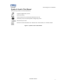
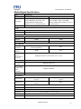
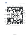
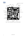
Media Engine™ User
Manual
Version 2.3
This document is the sole product and intellectual property of PFU Systems, Inc.
Copyright PFU Systems, Inc. 2001-2009.
Distribution or reproduction by permission only.
Media Engine™ User Manual
Introduction
Thank you for basing your system on our XScale based Media Engine™ Single Board Computer (SBC).
We are confident that it will help you get your product to market quickly while reducing overall
development cost.
The Media Engine User Manual explains the features, functions, and technical specifications for PFU
Systems Media Engine Single Board Computer. Specifically, it describes the board layout, connectors and
jumpers, active components, mechanical and environmental ratings, and provides signal descriptions.
Two versions of the Media Engine are available. One version includes 2700G Multimedia Accelerator to
drive LCD displays the other version uses the direct output of the processor to drive LCD display.
Review the information contained in this manual before using the Media Engine.
.
THE INFORMATION IN THIS DOCUMENT IS PROVIDED IN CONNECTION WITH PFU SYSTEMS
PRODUCTS. NO LICENSE, EXPRESS OR IMPLIED, BY ESTOPPEL OR OTHERWISE, TO ANY
INTELLECTUAL PROPERTY RIGHTS IS GRANTED BY THIS DOCUMENT. EXCEPT AS
PROVIDED IN PFU SYSTEMS’ TERMS AND CONDITIONS OF SALES FOR SUCH PRODUCTS,
PFU SYSTEMS ASSUMES NO LIABILITY WHATSOEVER, AND PFU SYSTEMS DISCLAIMS ANY
EXPRESS OR IMPLIED WARRANTY, RELATING TO SALE AND/OR USE OF PFU SYSTEMS
PRODUCTS INCLUDING LIABILITY OR WARRANTIES RELATING TO FITNESS FOR A
PARTICULAR PURPOSE, MERCHANTABILITY, OR INFRINGEMENT OF ANY PATENT,
COPYRIGHT OR OTHER INTELLECTUAL PROPERTY RIGHT. PFU SYSTEMS DOES NOT
WARRANT ITS PRODUCTS FOR USE IN APPLICATIONS WHICH MAY INVOLVE DANGERS TO
HUMAN HEALTH OR SAFETY, INCLUDING BUT NOT LIMITED TO MEDICAL LIFE SUPPORT,
SURGERY, AIRCRAFT FLIGHT CONTROL, AIR TRAFFIC CONTROL, MASS TRANSPORTATION
CONTROL, MISSILE LAUNCH AND OR GUIDANCE CONTROL, ENVIRONMENTAL CONTROL,
OR THE PLANNING CONSTRUCTION, MAINTENANCE, AND OPERATION OF A NUCLEAR
FACILITY.
Trademarks:
PFU Systems, Plug-N-Run, and Media Engine are trademarks of PFU Systems, Inc.
Intel and XScale are registered trademarks of Intel Corporation.
Microsoft, Windows, and Windows CE are registered trademarks of Microsoft Corporation in the United
States and/or in other countries.
All other trademarks and registered trademarks are property of their respective holders.
Copyright © 2009 Intel Corporation
All Rights Reserved, Copyright © 2009 PFU LIMITED
All Rights Reserved, Copyright © 2009 PFU Systems, Inc
Related Documentation
Please consult the following documents for additional information on the Media Engine.
Description
Type
Number
Media Engine Software User Manual
Manual
PS-XMESW-UM-xxx (*1, *2)
Table 1 - Related Documents
2
PS-XME-UM-023
Media Engine™ User Manual
*1 – xxx refers to current version.
*2 – Due to the confidential nature of the material in this document, a Non Disclosure Agreement between
the customer and PFU Systems must be executed. Please contact your PFU Systems sales representative for
details.
You can obtain the status of PFU Systems documents from PFU Systems web site (www.PFUsystems.com)
or requested from a PFU Systems sales representative. Many PFU documents can be downloaded form this
web site.
Applicable Media Engine Board Products
This manual is applicable to the following Media Engine Boards:
Part No.
Description
DRAM
Flash
2700G
Graphics
OS
PSXME12864GW
Media Engine™ with Intel PXA270
and 2700G Multimedia Accelerator
with 128MB DRAM, 64MB Flash &
Windows CE 5.0
128MB
64MB
Yes
Windows
CE 5.0
PSXME12864GL
Media Engine™ with Intel PXA270
and 2700G Multimedia Accelerator
with 128MB DRAM, 64MB Flash &
Linux Bootloader
128MB
64MB
Yes
Windows
CE 5.0
PSXME6432NW
Media Engine™ with Intel PXA270
– Native Graphics Option with
64MB DRAM, 32MB Flash &
Windows CE 5.0
64MB
32MB
No
Linux
Bootloader
PSXME6432NL
Media Engine™ with Intel PXA270
– Native Graphics Option with
64MB DRAM, 32MB Flash & Linux
Bootloader
64MB
32MB
No
Linux
Bootloader
Table 2 - Applicable Board Products
Development Kit
To get a head start, you may also want to order a Media Engine Development Kit for a complete set of
accessories for the Media Engine. The Media Engine Development Kit contains the items listed below.
Part No.
Description
PSXMEKITA
Media Engine Development Kit
12V/60W 100 ~ 240VAC AC Adapter with US AC power cable
Stereo Speaker Assembly
Registry Clear Plug
4-Wire Touch Panel
12.1” XGA 24bpp LVDS LCD Panel
LVDS Data Cable
Backlight Inverter
Inverter Cable
Printed version of this manual
Table 3 - Development Kit Contents
PS-XME-UM-023
3
Media Engine™ User Manual
Other Components You May Need
In addition to the items included with the Media Engine board package, you may need some or all of the
following components. These items can be ordered separately from PFU Systems.
USB Flash Drive
USB Key Board
USB Mouse
Secure Digital (SD) Card
Compact Flash (CF) Card
Table 4 - Other Components You May Need
Other Documents You May Need
These documents from other sources may be helpful in using the Media Engine.
Description
Source
Intel PXA270 Processor Datasheet
www.intel.com
Intel PXA27x Processor Family Design Guide
www.intel.com
Intel PXA27x Processor Family Developer’s Manual
www.intel.com
Intel 2700G Multimedia Accelerator Datasheet
www.intel.com
Intel 2700G Multimedia Accelerator Design Guide
www.intel.com
CF+ and CompactFlash Specification Revision 3.0
www.compactflash.org
Secure Digital Card Specifications
I2C Specifications
SPI Specifications
Table 5 - Other Documents You May Need
Layout of This Manual
Introduction
Provides an overview of package content and related materials.
Chapter 1 Installation and Startup
Describes how to install, configure, and set up the Media Engine and how to use the development kit.
Chapter 2 Design Overview
Provides a brief overview of the Media Engine board design.
Chapter 3 Features
Describes the implemented features of the Media Engine board.
Chapter 4 Mechanical Specifications
Provides dimensions and mounting details of the Media Engine board.
Chapter 5 Interface Specifications
Describes Media Engine I/O interface connector pin assignments.
Chapter 6 Operating System
Describes operating system considerations for the Media Engine.
4
PS-XME-UM-023
Media Engine™ User Manual
Symbols Used In This Manual
The following symbols are used in this manual:
Explains supplementary details.
Read as necessary.
.
Draws attention to a precaution that should be observed.
Alternately warns of an unacceptable or dangerous practice.
Should always be read!
References related information in a different area of this manual, or in another manual.
Figure 1: Symbols Used in This Manual
PS-XME-UM-023
5
Media Engine™ User Manual
Table of Contents
Introduction .................................................................................................................................................... 2
Trademarks: ............................................................................................................................................... 2
Related Documentation .............................................................................................................................. 2
Applicable Media Engine Board Products ................................................................................................. 3
Development Kit ................................................................................................................................... 3
Other Components You May Need ............................................................................................................ 4
Other Documents You May Need .............................................................................................................. 4
Layout of This Manual .............................................................................................................................. 4
Introduction ........................................................................................................................................... 4
Chapter 1 Installation and Startup ......................................................................................................... 4
Chapter 2 Design Overview .................................................................................................................. 4
Chapter 3 Features ................................................................................................................................ 4
Chapter 4 Mechanical Specifications .................................................................................................... 4
Chapter 5 Interface Specifications ........................................................................................................ 4
Chapter 6 Operating System ................................................................................................................. 4
Symbols Used In This Manual ................................................................................................................... 5
Table of Contents............................................................................................................................................ 6
List of Figures................................................................................................................................................. 8
List of Tables .................................................................................................................................................. 9
Chapter 1 – Installation and Startup ............................................................................................................. 10
Basic Media Engine Installation .............................................................................................................. 10
Unpacking the Media Engine SBC ..................................................................................................... 10
Installing the Media Engine SBC ........................................................................................................ 10
Media Engine Development Kit Installation............................................................................................ 10
Unpacking the Development Kit ......................................................................................................... 10
Assembly of the Development Kit and the Media Engine .................................................................. 10
Starting Up the Media Engine Operating System .................................................................................... 11
Chapter 2 – Design Overview....................................................................................................................... 12
Introduction.............................................................................................................................................. 12
Media Engine Block Diagram ................................................................................................................. 13
Media Engine Specifications ................................................................................................................... 15
Headers, Connectors, Switches and LEDs ............................................................................................... 17
Media Engine Connectors ................................................................................................................... 19
Switches .............................................................................................................................................. 20
LCD Table .......................................................................................................................................... 20
LED Indicators .................................................................................................................................... 20
Chapter 3 - Features ...................................................................................................................................... 21
10/100 Mbps Ethernet Support (1 Port) ................................................................................................... 21
AC Adapter Support ................................................................................................................................ 21
Secure Digital .......................................................................................................................................... 21
Serial Interface ......................................................................................................................................... 21
Touch Panel ............................................................................................................................................. 21
JTAG ....................................................................................................................................................... 21
CompactFlash .......................................................................................................................................... 22
6
PS-XME-UM-023
Media Engine™ User Manual
USB Interface ........................................................................................................................................... 22
Audio Support .......................................................................................................................................... 22
LCD Interface ........................................................................................................................................... 22
Backlight Inverter ..................................................................................................................................... 22
GPIO......................................................................................................................................................... 22
SPI ............................................................................................................................................................ 23
I2C ............................................................................................................................................................. 23
Chapter 4 Mechanical Specifications ............................................................................................................ 24
Top View .................................................................................................................................................. 24
Edge View ................................................................................................................................................ 25
Chapter 5 - Interface Specifications .............................................................................................................. 26
JTAG (J2) ................................................................................................................................................. 26
Ethernet (CN15) ....................................................................................................................................... 26
Touch Panel FPC (J17) ............................................................................................................................. 27
Touch Panel (J5) ....................................................................................................................................... 27
LCD Inverter (J7) ..................................................................................................................................... 27
2700G CMOS LCD (J8) ........................................................................................................................... 27
PXA270 CMOS LCD (J9) ........................................................................................................................ 28
2700G LVDS LCD (J3) ............................................................................................................................ 29
CompactFlash (J10) .................................................................................................................................. 30
Secure Digital (J14) .................................................................................................................................. 31
COM1 (CN5) ............................................................................................................................................ 31
I2C (J11) ................................................................................................................................................... 32
SPI (J12) ................................................................................................................................................... 32
IRDA/BT (J13) ......................................................................................................................................... 32
GPIO (J15) ............................................................................................................................................... 33
Speaker (J16) ............................................................................................................................................ 33
MIC IN (CN17) ........................................................................................................................................ 34
DC JACK (J6) .......................................................................................................................................... 34
USB (CN19, CN20).................................................................................................................................. 34
Chapter 6 Windows Operating System ......................................................................................................... 35
Operating System Installation................................................................................................................... 35
Registry Save Utility ................................................................................................................................ 35
To initiate the Registry Save Utility .................................................................................................... 35
Registry Clear Plug ................................................................................................................................... 36
Touch Panel Calibration ........................................................................................................................... 36
To calibrate the Media Engine ............................................................................................................. 36
Appendix A ................................................................................................................................................... 39
List of Clock Frequencies ......................................................................................................................... 39
Index .............................................................................................................................................................. 40
PS-XME-UM-023
7
Media Engine™ User Manual
List of Figures
Figure 1: Symbols Used in This Manual ........................................................................................................ 5
Figure 2: Touch Panel Lead Orientation ....................................................................................................... 11
Figure 3: Cable Connection Locations ......................................................................................................... 11
Figure 4 - Media Engine Block Level Diagram............................................................................................ 13
Figure 5 - Media Engine Block Level Diagram (Native Graphics Option) .................................................. 14
Figure 6 - Top View of Media Engine Connectors ....................................................................................... 17
Figure 7 - Top View of Media Engine Connectors (Native Graphics Option) ............................................. 18
Figure 8 - Media Engine Connector/Mounting Dimensions Top View ........................................................ 24
Figure 9 - Media Engine Connector/Mounting Dimensions Edge View ...................................................... 25
Figure 10 - Windows CE Start Menu ........................................................................................................... 35
Figure 11 - Prepare System for Shut Down Dialog Box............................................................................... 35
Figure 12 - It is now safe to turn off your computer ..................................................................................... 36
Figure 13 - Select Control Panel from the Start Menu ................................................................................. 36
Figure 14 - Stylus Properties Dialog Box ..................................................................................................... 37
Figure 15 - Calibrate Screen ......................................................................................................................... 37
8
PS-XME-UM-023
Media Engine™ User Manual
List of Tables
Table 1 - Related Documents ..........................................................................................................................2
Table 2 - Applicable Board Products ..............................................................................................................3
Table 3 - Development Kit Contents ...............................................................................................................3
Table 4 - Other Components You May Need ..................................................................................................4
Table 5 - Other Documents You May Need ....................................................................................................4
Table 6 - Media Engine Specifications.......................................................................................................... 16
Table 7 - Media Engine Connectors .............................................................................................................. 19
Table 8 - Momentary Switch SW1 ................................................................................................................ 20
Table 9 - DIP Switch SW3 ............................................................................................................................ 20
Table 10 - LCD Table ................................................................................................................................... 20
Table 11 - LED Indicators ............................................................................................................................. 20
Table 12 - PXA270 JTAG Pin Outs .............................................................................................................. 26
Table 13 - Ethernet RJ45 Pin Outs ................................................................................................................ 27
Table 14 - FPC Touch Panel Pin Outs ........................................................................................................... 27
Table 15 - Discrete Wire Touch Panel Pin Outs............................................................................................ 27
Table 16 - Inverter Backlight Pin Outs .......................................................................................................... 27
Table 17 - CMOS LCD Connector Pin Outs ................................................................................................. 28
Table 18 - PXA270 CMOS LCD Connector Pin Outs (Native Graphics Option) ........................................ 29
Table 19 - LVDS LCD Connector Pin Outs .................................................................................................. 30
Table 20 - Type II Socket Pin Outs ............................................................................................................... 31
Table 21 - Secure Digital Connector Pin Outs .............................................................................................. 31
Table 22 - COM1 Connector Pin Outs .......................................................................................................... 32
Table 23 - I2C Connector Pin Outs ............................................................................................................... 32
Table 24 - SPI Connector Pin Outs ............................................................................................................... 32
Table 25 - IRDA/BT Connector Pin Outs ..................................................................................................... 33
Table 26 - GPIO Connector Pin Outs ............................................................................................................ 33
Table 27 - Speaker Connector Pin Outs ........................................................................................................ 34
Table 28 - Microphone Connector Pin Outs .................................................................................................. 34
Table 29 - DC Jack Pin Outs ......................................................................................................................... 34
Table 30 - USB Connector Pin Outs ............................................................................................................. 34
Table 31 - Frequencies Used Internally by the Media Engine ...................................................................... 39
PS-XME-UM-023
9
Media Engine™ User Manual
1
Chapter 1 – Installation and Startup
This chapter describes how the Media Engine is packaged and how to prepare for the power on.
Basic Media Engine Installation
Installation and startup of the Media Engine Single Board Computer (SBC) in general purpose environment.
Unpacking the Media Engine SBC
The Media Engine ships with preconfigured DRAM Memory, Flash, and Operating System. User
modifications to the configurations are not generally possible.
Installing the Media Engine SBC
Mount the Media Engine Board in a suitable location. Refer to the chapter on Mechanical Specifications for
mounting information. Provide power to the Media Engine using a suitable power supply. Refer to the
Design Overview chapter for power requirements and the Interface Specifications chapter for connector
details.
There are five mounting holes on the Media Engine. These mounting holes have a diameter of 4.2
millimeter and a pad diameter of 8 millimeter. PFU Systems recommends using M3.5 screws for mounting.
Media Engine Development Kit Installation
Installation and startup of the Media Engine with the Media Engine Development Kit.
Unpacking the Development Kit
Media Engine Development Kit includes these items
4-Wire Touch Panel
12.1” XGA 24bpp LVDS LCD Panel
LVDS Data Cable
Backlight Inverter
Inverter Cable
Stereo Speaker Assembly
12V/60W 100 ~ 240VAC AC Adapter with US AC power cable
Registry Clear Plug
See the Media Engine Software User Manual for use of the Registry Clear Plug.
Assembly of the Development Kit and the Media Engine
Refer to the figures below for cabling locations.
1. Mount the Media Engine SBC, Stereo Speaker Assembly, LCD Panel, Touch Panel, and Backlight
Inverter on an appropriate foundation and locations relative to one another.
Refer to the Touch Panel instructions for installation to the LCD Panel.
Refer to the Media Engine SBC installation instructions above for mounting details.
2. Cable the Speaker Assembly to the Media Engine.
10
PS-XME-UM-023
Media Engine™ User Manual
3.
Cable the Touch Panel to the Media Engine.
Touch Panel
Caution: Connect
cable leads this way
4.
5.
Figure 2: Touch Panel Lead Orientation
Cable the LCD Panel with the LVDS Data Cable to the Media Engine.
Cable the LCD Panel to the Backlight Inverter and with the Inverter Cable to the Media Engine.
Touch Panel
Speaker
LVDS
Inverter
Figure 3: Cable Connection Locations
Starting Up the Media Engine Operating System
Connect the 12V AC Adapter and Power Cable to the Media Engine SBC.
When you apply power to the Media Engine, the operating system begins its startup process. As much as
15 seconds may elapse prior to the first image on the screen.
PS-XME-UM-023
11
Media Engine™ User Manual
2
Chapter 2 – Design Overview
This chapter provides a brief overview of the Media Engine SBC design.
Introduction
PFU Systems' Media Engine is a Single Board Computer designed with the following characteristics:
Low power
Small footprint
Industry standard ports
Connectors for common interconnect
While effective in many applications, the Media Engine was targeted to the following markets:
Indoor Media Display
Outdoor Media Display
Gasoline Service Applications
Retail Cabinet Media Display (Disposable Computer)
In addition, the Media Engine meets requirements for the embedded control market by providing these
ports:
SPI compliant Serial Synchronous Port
I2C Bus Specification, Version 2.0
General Purpose Input or Output (PXA270 GPIO)
IrDA (The IrDA capability is not currently validated.)
USB
RS-232
Serial Interfaces
A CompactFlash® Type II socket and a Secure Digital (SD) Card Slot provide connectivity to removable
solid-state storage devices for software upgrades and system storage.
12
PS-XME-UM-023
Media Engine™ User Manual
Media Engine Block Diagram
Inverter Control
LVDS LCD
24bpp
LVDS
Trans.
SDRAM
32MB
2700G
Multimedia
Accelerator
CMOS LCD
16bpp
Buffer
PXA270
SDRAM
128MB
(opt 64MB)
Ethernet
Controller
FLASH
64MB
(opt 32MB)
Buffer
RJ-45
CompactFlash
SD
USB Hub
4x USB 1.1
RTC
I2C
SPI
Transciever
RS-232
2x TTL Serial
GPIO
AC’97
CODEC/Touch
Panel Cont.
Speaker Out
Line In
Touch Panel
JTAG
Debug Port
DC/DC
Converters
Power Jack
Inverter Power
Figure 4 - Media Engine Block Level Diagram
PS-XME-UM-023
13
Media Engine™ User Manual
Inverter Control
CMOS LCD
16bpp
Buffer
SDRAM
128MB
(opt 64MB)
Ethernet
Controller
FLASH
64MB
(opt 32MB)
Buffer
RJ-45
CompactFlash
SD
USB Hub
4x USB 1.1
RTC
I2C
SPI
PXA270
Transciever
RS-232
2x TTL Serial
GPIO
AC’97
CODEC/Touch
Panel Cont.
Speaker Out
Line In
Touch Panel
JTAG
Debug Port
DC/DC
Converters
Power Jack
Inverter Power
Figure 5 - Media Engine Block Level Diagram (Native Graphics Option)
14
PS-XME-UM-023
Media Engine™ User Manual
Media Engine Specifications
Item
Specification
Model Number
PSXME12864GW/L
PSXME6432NW/L
Description
Media Engine™ with Intel PXA270 and
2700G Multimedia Accelerator with
128MB SDRAM, 64MB Flash &
Windows CE 5.0 or Linux Bootloader
Media Engine™ with Intel PXA270–
Native Graphics Option with 64MB
DRAM, 32MB Flash & Windows CE 5.0 or
Linux Bootloader
Processor
32-bit, 520 MHz Intel PXA270 processor
Cache
Data
32KB
Instruction
32KB
Memory
Internal SRAM
256KB
SDRAM
128MB
64MB
Flash
64MB
32MB
Intel® 2700G3 (Video up to 1024x768
color LCD interface)
None
32MB
None
IC Complement
Graphics
Accelerator
Graphics
Memory
Real Time
Clock (±3
min/month 0°C
to +50°C)
RTC Battery
Ethernet
Controller
AC’97 Audio
CODEC/Touch
Panel
Controller
USB Hub
Philips® PCF8563T ±5 min/month -20°C to +60°C
On board Lithium for RTC – Battery Duration 7+ years
SMCS® LAN91C11I
Philips® UCB1400
Philips® ISP1520BD
I/O Interfaces
CMOS LCD
1 x Single Channel 16bbp (64K) color
(41-pin)
1 x Single Channel 16bbp (64K) color
(41-pin)
LVDS LCD
1 x Single Channel 24bbp (64M) color
(30-pin)
None
I2C
1 x PXA270 I2C (4-pin)
SPI
1 x PXA270 SPI (6-pin)
GPIO
Serial Port
USB
Ethernet
10 x PXA270 GPIO (16-pin)
1 x RS-232 (DB-9), 2 x TTL (10-pin)
4 x USB 1.1 Host (Type A)
1x RJ-45
PS-XME-UM-023
15
Media Engine™ User Manual
Item
Specification
CompactFlash®
1 x Type II CF Socket
SD Card
1 x SD Slot
Audio
2 x 1W Stereo Speaker Out (6-pin)
Microphone
Mono Microphone Input 3.5mm Jack
JTAG
1 x PXA270 JTAG interface (20-pin)
Touch Panel
4-wire (1 x FPC, 1 x 4-pin header)
LCD Inverter
Control
+5V, +12V, Brightness Control (6-pin)
Physical
5” Length – 5” Width – 0.85” Height
Dimensions
Weight
3.9 ounces
Operating Environment
Ambient
Temperature
-20 – 60°C
Power Supply
12VDC +/-10%
Operating
Humidity
20 – 80% RH, no condensation
Shock
50G
Vibration
2.2G
MTBF
85,000 hours
Storage Environment
Ambient
Temperature
-20 – 65°C
0 – 90% RH, no condensation
Humidity
Power Consumption
Measured
Maximum w/
15”LCD
30W – Power Consumption was measured with a typical maximum configuration while
running all diagnostics. This measurement includes a large LCD with 4 back light tubes.
LCD p/n NEC NL10276BC30-17.
Measured
Maximum w/o
LCD
4W – Power Consumption was measured with a typical maximum configuration while
running all diagnostics. This measurement does not include a LCD.
Table 6 - Media Engine Specifications
16
PS-XME-UM-023
Media Engine™ User Manual
Headers, Connectors, Switches and LEDs
DC In
(J6)
Ethernet
(CN15)
COM1
(CN5)
USB
(CN19)
Reset Switch
(SW1) MIC In
USB
(CN20)
(CN17)
D1
D2
D3
Speaker
(J16)
Touch Panel
(J5)
CompactFlash
(J10)
Touch Panel
(J17)
Secure Digital
(J14)
2700G3 CMOS
(J8)
DIP Switch
(SW3)
2700G3 LVDS
(J3)
LCD Inverter
(J7)
PXA270
JTAG
(J2)
Factory Programming
Header
IRDA/BT
(J13)
SPI
(J12)
GPIO
(J15)
2
IC
(J11)
Mounting
Hole x5
(J6)
Figure 6 - Top View of Media Engine Connectors
PS-XME-UM-023
17
Media Engine™ User Manual
COM 1
(CN 5)
DC In
(J6)
Ethernet
(CN 15)
USB
(CN 20)
USB
(CN 19)
Reset Switch
(SW 1)
MIC In
(CN 17)
D1
Speaker
(J16)
D2
D3
Touch Panel
(J5)
Compact Flash
(J10)
Touch Panel
(J17)
PXA270 CMOS LCD
(J9)
Secure Digital
(J14)
DIP Switch
(Sw3)
Mounting Hole
(5 places)
LCD Inverter
(J7)
PXA270 JTAG
(J2)
Factory
Programming
Header
SPI
(J12)
IRDA/BT
(J13)
2
GPIO
(J15)
IC
(J11)
Figure 7 - Top View of Media Engine Connectors (Native Graphics Option)
18
PS-XME-UM-023
Media Engine™ User Manual
Media Engine Connectors
The table below lists all the connectors on the Media Engine SBC.
For some parts, the actual component used may be an equivalent part having the same
specification, but from a different manufacturer or with a different model number from the one
listed here.
Connector
Function
Type
Mfr.
Part No.
J2
JTAG
2x10/2.54mm
SAMTEC
MTSW-110-07G-D-240
CN15
Ethernet
RJ45
PULSE
J00-0065NL
J17
Touch Panel FPC
4-pin, SMT, FPC
FCI
SFW4S2STME1LF
J5
Touch Panel Wire
4-pin/2.54mm
MOLEX
22-23-2041
J7
LCD
Inverter/Brightness
6-pin/2.54mm
MOLEX
22-23-2061
J8 (not in Native
Graphics Option)
2700G CMOS
41-pin/1mm
HIROSE
DF9B-41P1V(32)
J9 (Native Graphics
Option only)
PXA270 CMOS
LCD
41-pin/1mm
HIROSE
DF9B-41P1V(32)
J3(not in Native
Graphics Option)
2700G LVDS
30-pin/1.25mm
HIROSE
DF13-30DP1.25V(56)
J10
CompactFlash in
Socket
Type II
DDK
MCDCEN750PE-FE
J14
Secure Digital
Bottom Mount
SD
MOLEX
54786-0971
CN5
COM1
DB-9, MALE
KYCON
K31X-E9P-N30
J11
I²C
2x2/2mm
HIROSE
DF11G-4DP2V(50)
J12
SPI
2x3/2mm
HIROSE
DF11G-6DP2V(50)
J13
IRDA/BT
2x5/2mm
HIROSE
DF11G-10DP2V(50)
J15
GPIO
2x8/2mm
HIROSE
DF11G-16DP2V(50)
J16
Speaker
2x3/2.54mm
SAMTEC
MTSW-103-07G-D-240
CN17
MIC In
Audio
Jack/3.5mm
KYCON
STX-3000
J6
DC Jack
Power
2.5mm/5.5mm
SWITCHCRAFT
RAPC712X
CN19-20
USB 1&2, USB 3&4
Dual Stack USB
TYCO/AMP
5787617-1
Table 7 - Media Engine Connectors
PS-XME-UM-023
19
Media Engine™ User Manual
Switches
Momentary Switch SW1
Switch
Function
SW1
Reset Switch
Table 8 - Momentary Switch SW1
DIP Switch SW3
Switch #
Function
On
Off
Default
1
IRDA/Serial
IRDA
Serial (*1)
Off
2
LCD Type 1
Refer to LCD
Table
Refer to LCD
Table
On
3
LCD Type 2
Refer to LCD
Table
Refer to LCD
Table
On
4
Reserved
Reserved
Reserved
(*2)
*1. IRDA functionality is not validated at this time.
*2. Switch 4 is set at the factory. Changing the setting will result in unstable operation.
*3. Switches 2 & 3 are not applicable to the Native Graphics Option and should be left unchanged.
Table 9 - DIP Switch SW3
LCD Table
LCD Type 1
(Switch 2)
LCD Type 2
(Switch 3)
Qualified LCD’s (Contact PFU for a current list)
Manufacturer
P/N
Resolution
OFF (default
position)
OFF (default
position)
NEC
NEC
NL10276BC30-17
NL10276BC24-13
XGA 15”
XGA 12.1”
ON
OFF
NEC
NL8060BC26-27
SVGA
OFF
ON
NEC
NL6448BC20-08
VGA
ON
ON
Reserved
Reserved
Reserved
Table 10 - LCD Table
LED Indicators
LED
Color
Function
D1
Red
Diagnostics (GPIO52)
D2
Yellow
Diagnostics (GPIO53)
D3
Green
VCCBAT (PXA270 Initial Power)
CN15
Green &
Yellow
Yellow On & Green Off = 10Mbps Link
Yellow ON & Green ON = 100Mbps
Table 11 - LED Indicators
20
PS-XME-UM-023
Media Engine™ User Manual
3
Chapter 3 - Features
This chapter describes the implemented features of the Media Engine board.
10/100 Mbps Ethernet Support (1 Port)
The Media Engine uses a SMSC LAN91C111 single chip MAC and PHY Ethernet controller. The
Controller supports 10/100Mbps networks, Full/Half Duplex and Auto Negotiation. The Ethernet port uses
an industry standard RJ-45 connector (CN15) with LED’s for Link and Speed. An Ethernet crossover cable
is required to connect directly to a host.
AC Adapter Support
The Media Engine requires the use of a 12VDC AC Adapter connected to the DC-IN jack (J6) with a
30W~60W power rating depending on the peripherals attached to it.
Secure Digital
The Media Engine provides one SD (Secure Digital) interface. This interface supports the bus protocol
identified in the MMC System Specification 3.2 and SD Memory Card, Specification Version 1.01 and
SDIO Memory Card Specification Version 1.0.
Serial Interface
Three 16550A compatible UARTS are provided. COM1 is a full function RS232 serial port that uses a
standard 9-pin D-SUB male connector (CN5). COM2 is a 4-wire CMOS level serial interface that supports
RTS & CTS on a 10-pin header (J13). COM3 is a 2-wire CMOS level serial interface that does not support
any modem control, these signals are also on connector (J13).
Maximum data rate for COM2 is 38400.
Touch Panel
The Media Engine supports a 4-wire resistive touch screen interface. The touch screen can be connected
directly using a FPC type connector (J17) or discrete wire connector (J5) with a custom adapter board.
JTAG
The Media Engine provides a debug JTAG port (J2) that conforms to the IEEE Std. 1149.1–1990 and IEEE
Std. 1149.1a-1993, Standard Test Access Port and Boundary-Scan Architecture. This port is only
connected to the PXA270 and is used for software debugging and programming the flash memory.
Contact your local PFU Systems sales representative for qualified Software Development tools.
PS-XME-UM-023
21
Media Engine™ User Manual
CompactFlash
The Media Engine supports one Type II CompactFlash slot (J10). The CompactFlash interface conforms to
CF+ and CompactFlash Specification Version 1.4.
.
The CF interface does not support removal or insertion (hot-swappable) while the Media
Engine is powered.
USB Interface
The Media Engine supports four host USB 1.1 ports using two dual-stacked connectors (CN19 & CN20).
.
The Media Engine can provide up to 0.5A to each USB 1.1 port. A current limiting device
provides over-current protection for each port and will open when the current draw exceeds
0.5A. This device is self-resetting when the fault condition is removed.
Audio Support
The Media Engine uses a Philips UCB1400 20-bit stereo audio Codec. The speaker out header (J16)
features 1 Watt per channel output power to directly drive two external 8-ohm speakers. The microphone
interface uses an industry standard 3.5mm connector (CN17) and supplies a 2.25V reference voltage.
LCD Interface
The Media Engine uses the Intel® 2700G Multimedia Accelerator with 32MB of video memory for high
performance graphics and video acceleration. Direct connection to a TFT LCD can be made through the
parallel CMOS 16bpp (bits-per-pixel) 41-pin connector (J8) or from the serial LVDS 24bpp 30-pin
connector (J3). The Media Engine is preconfigured to support VGA, SVGA or XGA LCD panels from
NEC. See the LCD Table (Table 10) for the supported panels that can be selected with the dip switch
(SW3). The Native Graphics Option version of the Media Engine without the 2700G Multimedia
Accelerator can be directly connected to a TFT LCD through the parallel CMOS 16bpp 41-pin connector
(J9).
Contact your local PFU Systems sales representative if support for a different LCD panel is
required.
Backlight Inverter
The Media Engine provides switched power for 5V or 12V backlight inverters on a 6-pin connector (J7).
LCD brightness control is also supported through a digital potentiometer controlled through an API.
GPIO
Each GPIO pin can be programmed as an input or output. When programmed as an input, a GPIO can also
serve as an interrupt source to sample rising or falling edges. When programmed as an output the GPIO’s
can be individually cleared or set. See PXA27x Processor Family Developer’s Manual for more
information on configuring GPIO. This interface is provided on a 16-pin shrouded header (J15).
.
22
Most GPIO pins are 3.3V tolerant. GPIO_EXPAND5 and GPIO_EXPAND6 are 2.5V
tolerant. Level translation must be performed for voltages exceeding these levels. GPIO pins
are not intended for driving heavy loads.
PS-XME-UM-023
Media Engine™ User Manual
SPI
The Media Engine provides one Serial Synchronous Port that supports the Motorola SPI full-duplex
protocol. This interface is provided through a 6-pin shrouded header (J12).
I 2C
The Media Engine supports one I2C interface (J11) that is compliant with I2C Bus Specification, Version
2.0. This interface features multi-master and arbitration support. The bus can operate at a standard-speed of
100kbs or fast-mode at 400kbps.
PS-XME-UM-023
23
Media Engine™ User Manual
4
Chapter 4 Mechanical Specifications
This chapter provides the dimensions of the Media Engine board in millimeters.
Top View
115.57
99.31
59.63
46.93
29.15
1.27
0.67
127
109.22
93.85
85.73
58.42
52.28
5.72
60.96
118.11
4.45
127
Figure 8 - Media Engine Connector/Mounting Dimensions Top View
24
PS-XME-UM-023
Media Engine™ User Manual
Edge View
15.49
13.59
4.5
6.77
1.6
Figure 9 - Media Engine Connector/Mounting Dimensions Edge View
The mounting holes for the Media Engine are 4.2 millimeters in diameter with an 8-millimeter pad. This
hole size best accommodates an M3.5 screw.
2.9
PS-XME-UM-023
25
Media Engine™ User Manual
5
Chapter 5 - Interface Specifications
This chapter provides detailed pin assignments and signal names for each individual interface.
JTAG (J2)
No.
Signal
Description
No.
Signal
Description
1
POWER
VCCBAT(3.3V early)
11
NC
No Connection
2
POWER
VCCBAT(3.3V early)
12
GND
Ground
3
JTAG_TRST#
PXA270 TRST#
13
JTAG_TDO
PXA270 TDO
4
GND
Ground
14
GND
Ground
5
JTAG_TDI
PXA270 TDI
15
RESET_IN
PXA270
RESET#
6
GND
Ground
16
GND
Ground
7
JTAG_TMS
PXA270 TMS
17
NC
No Connection
8
GND
Ground
18
GND
Ground
9
JTAG_TCLK
PXA270 TCLK
19
NC
No Connection
10
GND
Ground
20
GND
Ground
Table 12 - PXA270 JTAG Pin Outs
Ethernet (CN15)
No.
Signal
1
TPO_P
2
TPO_N
3
TPI_P
4
VCC3R3
5
NC
6
TPI_N
7
NC
26
PS-XME-UM-023
Media Engine™ User Manual
No.
Signal
8
Ground
Table 13 - Ethernet RJ45 Pin Outs
Touch Panel FPC (J17)
No.
Signal
Description
1
TSMY
Touch Screen Negative Y-plate
2
TSMX
Touch Screen Negative X-plate
3
TSPY
Touch Screen Positive Y-plate
4
TSPX
Touch Screen Positive X-plate
Table 14 - FPC Touch Panel Pin Outs
Touch Panel (J5)
No.
Signal
Description
1
TSPX
Touch Screen Positive X-plate
2
TSPY
Touch Screen Positive Y-plate
3
TSMX
Touch Screen Negative X-plate
4
TSMY
Touch Screen Negative Y-plate
Table 15 - Discrete Wire Touch Panel Pin Outs
LCD Inverter (J7)
No.
Signal
Description
1
VCC12
Switched 12V
2
GND
Ground
3
GND
Ground
4
VCC5
Switched 5V
5
DPOT_VL
Digital POT HIGH-SIDE
6
DPOT_VW
Digital POT LOW-SIDE
Table 16 - Inverter Backlight Pin Outs
2700G CMOS LCD (J8)
No.
Signal
Description
No.
Signal
Description
1
GND
GROUND
22
GND
GROUND
2
LCD1_PCLK
LCD DOT CLOCK
23
LCD1_D13
LCD G3
3
GND
GROUND
24
LCD1_D14
LCD G4
4
LCD1_LCLK
LCD H-SYNC
25
LCD1_D15
LCD G5
5
LCD1_FCLK
LCD V-SYNC
26
GND
GROUND
6
GND
GROUND
27
GND
GROUND
PS-XME-UM-023
27
Media Engine™ User Manual
No.
Signal
Description
No.
Signal
Description
7
GND
GROUND
28
GND
GROUND
8
GND
GROUND
29
LCD1_D2
LCD B0
9
LCD1_D18
LCD R0
30
LCD1_D3
LCD B1
10
LCD1_D19
LCD R1
31
LCD1_D4
LCD B2
11
LCD1_D20
LCD R2
32
GND
GROUND
12
GND
GROUND
33
LCD1_D5
LCD B3
13
LCD1_D21
LCD R3
34
LCD1_D6
LCD B4
14
LCD1_D22
LCD R4
35
LCD1_D7
LCD B5
15
LCD1_D23
LCD R5
36
GND
GROUND
16
GND
GROUND
37
LCD1_DEN
LCD DATA
ENABLE
17
GND
GROUND
38
N/C
NO CONNECTION
18
GND
GROUND
39
VCC_LCD
SWITCHED 3.3V
19
LCD1_D10
LCD G0
40
VCC_LCD
SWITCHED 3.3V
20
LCD1_D11
LCD G1
41
GND
GROUND
21
LCD1_D12
LCD G2
Table 17 - CMOS LCD Connector Pin Outs
PXA270 CMOS LCD (J9)
No.
Signal
Description
No.
Signal
Description
1
GND
GROUND
22
GND
GROUND
2
LCD_PCLK
LCD DOT CLOCK
23
LCD_D9
LCD G4
3
GND
GROUND
24
LCD_D10
LCD G5
4
LCD_LCLK
LCD H-SYNC
25
LCD_D11
LCD R0
5
LCD_FCLK
LCD V-SYNC
26
GND
GROUND
6
GND
GROUND
27
GND
GROUND
7
GND
GROUND
28
GND
GROUND
8
GND
GROUND
29
LCD_D0
LCD B0
9
LCD_D12
LCD R1
30
LCD_D1
LCD B1
10
LCD_D13
LCD R2
31
LCD_D2
LCD B2
11
LCD_D14
LCD R3
32
GND
GROUND
12
GND
GROUND
33
LCD_D3
LCD B3
28
PS-XME-UM-023
Media Engine™ User Manual
No.
Signal
Description
No.
Signal
Description
13
LCD_D15
LCD R4
34
LCD_D4
LCD B4
14
LCD_D16
RESERVED
35
LCD_D5
LCD G0
15
LCD_D17
RESERVED
36
GND
GROUND
16
GND
GROUND
37
LCD_BIAS
LCD DATA
ENABLE
17
GND
GROUND
38
VCC_LCD
SWITCHED 3.3V
18
GND
GROUND
39
VCC_LCD
SWITCHED 3.3V
19
LCD_D6
LCD G1
40
VCC_LCD
SWITCHED 3.3V
20
LCD_D7
LCD G2
41
LCD_MODE
GROUND
21
LCD_D8
LCD G3
Table 18 - PXA270 CMOS LCD Connector Pin Outs (Native Graphics Option)
2700G LVDS LCD (J3)
No.
Signal
Description
No.
Signal
Description
1
VCC_LCD
SWITCHED 3.3V
2
VCC_LCD
SWITCHED
3.3V
3
TXOUT3+
LCD[GND,B1,B0,G1,G0,R1,R0]
4
VCC_LCD
SWITCHED
3.3V
5
TXOUT3-
LCD[GND,B1,B0,G1,G0,R1,R0]
6
GND
GROUND
7
GND
GROUND
8
GND
GROUND
9
TXCLKOUT+
LCD DOT CLOCK
10
GND
GROUND
11
TXCLKOUT-
LCD DOT CLOCK
12
GND
GROUND
13
GND
GROUND
14
GND
GROUND
15
TXOUT2+
LCD[DATA EN, V-SYNC,H-SYNC,
B7,B6,B5,B4]
16
GND
GROUND
17
TXOUT2-
LCD[DATA EN, V-SYNC,H-SYNC,
B7,B6,B5,B4]
18
GND
GROUND
19
GND
GROUND
20
GND
GROUND
21
TXOUT1+
LCD[B3,B2,G7,G6,G5,G4,G3]
22
GND
GROUND
23
TXOUT1-
LCD[B3,B2,G7,G6,G5,G4,G3]
24
GND
GROUND
25
GND
GROUND
26
GND
GROUND
27
TXOUT0+
LCD[G2,R7,R6,R5,R4,R3,R2]
28
GND
GROUND
29
TXOUT0-
LCD[G2,R7,R6,R5,R4,R3,R2]
30
GND
GROUND
PS-XME-UM-023
29
Media Engine™ User Manual
No.
Signal
Description
No.
Signal
Description
Table 19 - LVDS LCD Connector Pin Outs
CompactFlash (J10)
No.
Signal
Description
No.
Signal
Description
1
GND
GROUND
26
CF_CD2#
CD CD2
2
CF_D3
CF D03
27
CF_D11
CF D11
3
CF_D4
CF D04
28
CF_D12
CF D12
4
CF_D5
CF D05
29
CF_D13
CF D13
5
CF_D6
CF D06
30
CF_D14
CF D14
6
CF_D7
CF D07
31
CF_D15
CF D15
7
CF_PCE1#
CF –CE1
32
CF_PCE2#
CF-CE2
8
CF_A10
CF A10
33
NC
NO CONNECTION
9
CF_POE#
CF –OE
34
CF_PI0R#
CF –IORD
10
CF_A9
CF A09
35
CF_PI0W#
CF –IOWR
11
CF_A8
CF A08
36
CF_PWE#
CF –WE
12
CF_A7
CF A07
37
CF_RDY
CF IREQ
13
VCC3R3
3.3V
38
VCC3R3
3.3V
14
CF_A6
CF A06
39
GND
GROUND
15
CF_A5
CF A05
40
NC
NO CONNECTION
16
CF_A4
CF A04
41
CF_RESET_CPU
CF RESET
17
CF_A3
CF A03
42
CF_PWAIT#
CF –WAIT
18
CF_A2
CF A02
43
NC
NO CONNECTION
19
CF_A1
CF A01
44
CF_PREG#
CF –REG
20
CF_A0
CF A00
45
NC
NO CONNECTION
21
CF_D0
CF D00
46
NC
NO CONNECTION
22
CF_D1
CF D01
47
CF_D8
CF D08
23
CF_D2
CF D02
48
CF_D9
CF D09
24
CF_I0IS16#
CF –IOIS16
49
CF_D10
CF D10
25
CF_CD1#
CF CD1
50
GND
GROUND
30
PS-XME-UM-023
Media Engine™ User Manual
No.
Signal
Description
No.
Signal
Description
Table 20 - Type II Socket Pin Outs
Secure Digital (J14)
No.
Signal
Description
1
MM_DAT3
SD Data Line 3
2
MM_CMD
SD Command Line
3
GND
GROUND
4
VCC_MM
Switched 3.3V
5
MM_CLK
SD Clock
6
GND
GROUND
7
MM_DAT0
SD DATA LINE 0
8
MM_DAT1
SD DATA LINE 1
9
MM_DAT2
SD DATA LINE 2
10
MM_WP
SD WRITE
PROTECT
11
GND
GROUND
12
MM_CD
SD CARD
DETECT
Table 21 - Secure Digital Connector Pin Outs
COM1 (CN5)
No.
Signal
Description
1
SERA_DCD
Carrier Detected
2
SERA_RxD
Receive Data
3
SERA_TxD
Send Data
4
SERA_DTR
Data Terminal Ready
5
GND
Ground
PS-XME-UM-023
31
Media Engine™ User Manual
No.
Signal
Description
6
SERA_DSR
Data Set Ready
7
SERA_RTS
Request To Send
8
SERA_CTS
Clear To Send
9
SERA_RI
Ring Indicator
10
GND
Ground
11
GND
Ground
Table 22 - COM1 Connector Pin Outs
I2C (J11)
No.
Signal
Description
1
I2C_SCL
I2C Serial Clock
2
VCC3R3
3.3V
3
GND
Ground
4
I2C_SDA
I2C Serial Data
Table 23 - I2C Connector Pin Outs
SPI (J12)
No.
Signal
Description
1
SPI_FRM
SPI Frame
2
SPI_CLK
SPI Clock
3
SPI_RXD
SPI Receive Data
4
SPI_TXD
SPI Transmit Data
5
GND
Ground
6
NC
RESERVED - DO
NOT USE
Table 24 - SPI Connector Pin Outs
IRDA/BT (J13)
No.
Signal
Description
1
IRDA_TXD
IRDA Transmit Data
2
VCC3R3
3.3V
3
IRDA_EN#
IRDA –Enable
4
IRDA_RXD
IRDA Receive Data
5
BT_RXD
Blue Tooth Receive Data
6
GND
Ground
7
BT_CTS
Blue Tooth Clear to Send
8
BT_TXD
Blue Tooth Transmit Data
32
PS-XME-UM-023
Media Engine™ User Manual
No.
Signal
Description
9
GND
Ground
10
BT_RTS
Blue Tooth Request to Send
Table 25 - IRDA/BT Connector Pin Outs
GPIO (J15)
No.
Signal
Description
No.
Signal
Description
1
GPIO_EXPAND1
General Purpose Input
or Output (PXA270
GPIO84)
9
GPIO_EXPAND7
General Purpose
Input or Output
(PXA270 GPIO93)
2
GND
Ground
10
GND
3
GND
Ground
11
GPIO_EXPAND9
General Purpose
Input or Output
(PXA270 GPIO95)
4
GPIO_EXPAND2
General Purpose Input
or Output (PXA270
GPIO83)
12
GPIO_EXPAND8
General Purpose
Input or Output
(PXA270 GPIO94)
5
GPIO_EXPAND4
General Purpose Input
or Output (PXA270
GPIO82)
13
GPIO_EXPAND10
General Purpose
Input or Output
(PXA270 GPIO106)
6
GPIO_EXPAND3
General Purpose Input
or Output (PXA270
GPIO81)
14
GND
Ground
7
GPIO_EXPAND6
General Purpose Input
or Output (PXA270
GPIO14)
15
GND
Ground
8
GPIO_EXPAND5
General Purpose Input
or Output (PXA270
GPIO19)
16
RESET
Reset from PXA270
(Active High)
Table 26 - GPIO Connector Pin Outs
Speaker (J16)
No.
Signal
Description
1
LINE_OUTL_P
Left Speaker Positive
2
LINE_OUTR_P
Right Speaker Positive
3
GND_AUD
Ground
4
GND_AUD
Ground
PS-XME-UM-023
33
Media Engine™ User Manual
No.
Signal
Description
5
LINE_OUTL_N
Left Speaker Negative
6
LINE_OUTR_N
Right Speaker Negative
Table 27 - Speaker Connector Pin Outs
MIC IN (CN17)
No.
Signal
Description
1
GND_AUD
Ground
2
MIC
Microphone In
3
MIC_REF
Reference Voltage 2.25V
Table 28 - Microphone Connector Pin Outs
DC JACK (J6)
No.
1
2
3
Signal
Description
+ Connection
12V DC
NC
No Connection
- Connection
GND
Table 29 - DC Jack Pin Outs
USB (CN19, CN20)
No.
Signal
Description
1
VCCx (*1)
USB Port x Power Port 1
and 3 respectively for
CN19 and CN20 (*1)
2
USBx- (*1)
USB 1.1 Port x Data (*1)
3
USBx+ (*1)
USB 1.1 Port x Data (*1)
4
GND
Ground
5
VCCy (*2)
USB Port y Power (*2)
6
USBy- (*2)
USB 1.1 Port y Data (*2)
7
USBy+ (*2)
USB 1.1 Port y Data (*2)
8
GND
Ground
*1 Port 1 and 3 respectively for CN19 and CN20.
*2 Port 2 and 4 respectively for CN19 and CN20.
Table 30 - USB Connector Pin Outs
34
PS-XME-UM-023
Media Engine™ User Manual
6
Chapter 6 Windows Operating System
Describes operating system considerations for the Media Engine. Refer to the Media Engine Software User
Manual (PS-XMESW-UM-xxx) for details about the Media Engine use of Windows CE and application
integration.
Operating System Installation
The Windows version of the Media Engine comes with the Windows® CE operating system already
installed. A Certificate of Authenticity is included in the board package.
Registry Save Utility
The Media Engine provides an interface to save registry settings that are vital to system operation. The
registry save utility saves information such as LAN Settings, Volume Level, LCD Brightness, and others.
This utility is part of the shutdown sequence.
To initiate the Registry Save Utility
1.
Select Shutdown in the Start Menu.
Figure 10 - Windows CE Start Menu
The Prepare system for shut down dialog box opens.
Figure 11 - Prepare System for Shut Down Dialog Box
This dialog box offers three choices.
2.
Pressing the "OK" button executes a Registry Save and results in the message "It is now safe to turn
off your computer." Note that this will save your current registry settings
PS-XME-UM-023
35
Media Engine™ User Manual
3.
4.
Figure 12 - It is now safe to turn off your computer
Pressing the "Shut down without saving settings" button will also result in the message "It is now safe
to turn off your computer." Note that this will not save any new registry settings.
Pressing the "Cancel" button clears the screen and returns to the previous window.
Registry Clear Plug
A registry clear plug is provided in the Media Engine Development Kit. This plug is used to restore the
operating system registry to the factory defaults. See the Media Engine Software User Manual for details of
the use of the Registry Clear Plug.
Touch Panel Calibration
The Media Engine provides a touch panel calibration utility. This utility assists in aligning the touch panel's
coordinates to the LCD.
To calibrate the Media Engine
1.
Select Control Panel from the Start Menu.
Figure 13 - Select Control Panel from the Start Menu
The Control Panel opens.
2.
Start the calibration utility by selecting the stylus icon on the Control Panel.
The Stylus Properties Dialog box opens.
3. Select the Calibration tab.
36
PS-XME-UM-023
Media Engine™ User Manual
4.
Figure 14 - Stylus Properties Dialog Box
Select the Recalibrate button to start the procedure.
The calibration screen opens.
Figure 15 - Calibrate Screen
A blank screen with a cross opens.
PS-XME-UM-023
37
Media Engine™ User Manual
5.
Press and hold the stylus on the center of the cross until the cross moves to the next target position.
Use a stylus instead of a finger.
6.
7.
Repeat this procedure for the five different locations.
When the calibration is successfully completed, the window closes.
38
PS-XME-UM-023
Media Engine™ User Manual
A
Appendix A
List of Clock Frequencies
The table below shows the list of clock frequencies used internally by the Media Engine.
Element
Frequency
Crystal X2
13.000 MHz
Crystal
25.000 MHz
Crystal
24.576 MHz
Crystal
12.000 MHz
Crystal
32.768 KHz
Table 31 - Frequencies Used Internally by the Media Engine
PS-XME-UM-023
39
Media Engine™ User Manual
Index
2700G ........................... 2, 3, 4, 15, 19, 22, 27, 29
AC Adapter .......................................3, 10, 11, 21
Audio .............................................. 15, 16, 19, 22
Backlight Inverter ............................. 3, 10, 11, 22
Battery ..............................................................15
Cache ................................................................15
CD ..............................................................30, 31
COM1 ............................................. 19, 21, 31, 32
CompactFlash ....................... 4, 12, 16, 19, 22, 30
Configurations ..................................................10
Connectors2, 4, 10, 12, 17, 18, 19, 21, 22, 24, 25,
28, 29, 30, 31, 32, 33, 34
Design .....................................................4, 10, 12
Development Kit...........................................3, 10
DRAM ....................................................3, 10, 15
Environment ...............................................10, 16
Environmental ................................................... 2
Ethernet..................................... 15, 19, 21, 26, 27
Flash ................................................... 3, 4, 10, 15
GPIO ......................................... 12, 15, 19, 22, 33
Graphics .................... 3, 14, 15, 18, 19, 20, 22, 29
Headers .............................................................17
I2C ............................................... 4, 12, 15, 23, 32
Installation ..............................................4, 10, 35
Intel ................................................. 2, 3, 4, 15, 22
Interface .............. 4, 10, 15, 16, 21, 22, 23, 26, 35
Inverter Cable .........................................3, 10, 11
IrDA.......................................... 12, 19, 20, 32, 33
JTAG .............................................. 16, 19, 21, 26
LCD ... 2, 3, 10, 11, 15, 16, 19, 20, 22, 27, 28, 29,
30, 35, 36
LCD Inverter ........................................16, 19, 27
LED ..................................................................20
LVDS........................ 3, 10, 11, 15, 19, 22, 29, 30
Media Engine1, 2, 3, 4, 10, 11, 12, 13, 14, 15, 16,
17, 18, 19, 21, 22, 23, 24, 25, 35, 36, 39
40
Media Engine Development Kit ............ 3, 10, 36
Memory ..........................................10, 15, 21, 22
MIC............................................................ 19, 34
Microphone .......................................... 16, 22, 34
Operation ................................................... 20, 35
Part ......................................................... 3, 19, 35
Plug-N-Run ........................................................ 2
Power ............ 3, 10, 11, 12, 16, 19, 20, 21, 22, 34
Power Cable ..................................................... 11
Power Supply ................................................... 16
PXA270 ... 3, 4, 12, 15, 16, 19, 20, 21, 26, 28, 29,
33
Real Time ........................................................ 15
Real Time Clock .............................................. 15
Registry ............................................ 3, 10, 35, 36
Registry Clear Plug ................................ 3, 10, 36
Registry Save Utility........................................ 35
Secure Digital .............................4, 12, 19, 21, 31
Serial ............................. 12, 15, 20, 21, 22, 23, 32
Shut Down ....................................................... 35
Software ................................2, 10, 12, 21, 35, 36
Speaker .....................................10, 19, 22, 33, 34
Specification ...................4, 12, 15, 19, 21, 22, 23
Specifications ....................2, 4, 10, 15, 16, 24, 26
SPI ........................................4, 12, 15, 19, 23, 32
Stereo Speaker ....................................... 3, 10, 16
Support................................................. 21, 22, 23
Switches ............................................... 17, 20, 22
Touch Panel ........ 3, 10, 11, 15, 16, 19, 21, 27, 36
USB ......................................4, 12, 15, 19, 22, 34
Version..............................2, 3, 12, 21, 22, 23, 35
Voltage....................................................... 22, 34
Web Site ............................................................ 3
Windows CE ...................................... 2, 3, 15, 35
XScale ................................................................ 2
PS-XME-UM-023