1
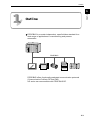
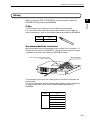
FUJI UG SERIES PROGRAMMABLE OPERATION DISPLAY
USER'S MANUAL
<PROFIBUS Communications>
TYPE: UG03I-P
FEH368a
Preface
Thank you very much for purchasing the Fuji UG Series Programmable Operation Display.
This manual describes how to use the Profibus interface type.
This manual will help you understand the outline information and to master it efficiently by
giving examples in each chapter.
In addition to this manual, the following manuals on the UG Series are available. Please
ask your nearest dealer for the appropriate manuals and read them too.
Name
Manual No.
Contents
UG Series User’s Manual
<Operation>
FEH375
Describes how to operate the screen editor
(UG00S-CW) for the UG Series.
UG Series User’s Manual
<Function>
FEH376
Describes the functions of the UG Series.
UG30 Series User’s Manual
<Hardware>
FEH377
Describes the hardware of the 530/430/330
Series.
UG20 Series User’s Manual
<Hardware>
FEH352
Describes the hardware of the 520/420/320/
220/221 Series.
Notes
(1) No part of this manual may be reproduced in any form without the prior permission of the
publisher.
(2) The contents of this manual, including the specifications, are subject to change without notice
for the purposes of improvement.
(3) This manual was prepared with the utmost care. However, if you find any ambiguity, errors,
etc., please contact any of our sales offices that are listed at the end of this manual. When you
do so, be sure to quote the manual number given on the cover of this manual.
Record of Revisions
The manual number is shown at the bottom right of the front cover.
Printing Date
Reference No.
Revised Contents
February, 2001
FEH368
1st Edition printed
January, 2003
FEH368a
2nd Edition printed
• Explanations on UG30 Series added
• Some explanations reviewed added
Contents
Preface
Record of Revisions
1. Outline ............................................................................. 1-1
2. Specifications ................................................................... 2-1
PROFIBUS Communication Specifications ...............................................2-1
3. Setting at the POD Side & Wiring ...................................... 3-1
Installation to the POD and Setting ........................................................3-1
Communication interface unit ........................................................................ 3-1
Dimensions of PROFIBUS I/F unit .................................................................. 3-2
How to install a PROFIBUS I/F unit ................................................................ 3-4
Notes on the CE specification ......................................................................... 3-5
Setting at PROFIBUS I/F Unit Side .........................................................3-6
Outline of PROFIBUS I/F unit (UG03I-P) .......................................................... 3-6
Wiring........... ..........................................................................................3-7
Cable........... ................................................................................................... 3-7
Recommended bus connector ......................................................................... 3-7
4. Connection of PLC ............................................................ 4-1
Interpreting Communication................................................................... 4-1
Outline........ ................................................................................................... 4-1
Available memories ......................................................................................... 4-2
Setting in SIMATIC Manager ................................................................... 4-3
Our software package ...................................................................................... 4-3
Registration of POD ........................................................................................ 4-4
Setting of Hardware Configuration .................................................................. 4-5
Setting of Function ......................................................................................... 4-8
5. Screen Data Editing .......................................................... 5-1
Select PLC type .......................................................................................5-1
Communication Parameter .....................................................................5-2
No. of Words Setting for I/O ............................................................................ 5-2
6. Error ................................................................................. 6-1
Communication Error (Time-Out) ............................................................6-1
If (Time-Out) happens instantly; ..................................................................... 6-2
If (Time-Out) happens after a screen is displayed for a moment; ..................... 6-2
Outline
1
Outline
1
Outline
PROFIBUS is a vendor-independent, open field bus standard for a
wide range of applications in manufacturing and process
automation.
···
···
···
···
···
··· ···
··· ···
···
···
···
···
···
···
···
···
···
···
···
···
···
···
··· ···
···
··· ···
···
···
···
PROFIBUS
·····················
·····················
·····················
·····················
·····················
·· · ·· ·· ·· ··
···
···
···
···
···
···
||||||||||||||||||||||||||||||||
||||||||||||||||||||||||||||||||
PROFIBUS offers functionally graduated communication protocols
(Communication Profiles): DP and FMS.
UG series can communicate with PROFIBUS-DP.
1-1
Outline
UG series can communicate with PROFIBUS-DP with the
communication interface unit, UG03I-P, attached onto POD.
···
···
···
···
···
··· ···
··· ···
···
···
···
···
···
···
···
···
···
···
···
···
···
···
··· ···
···
··· ···
···
···
···
Master
Slave
PROFIBUS-DP (RS-485)
·····················
·····················
·····················
·····················
·····················
·· · ·· ·· ·· ··
+
···
···
···
···
···
···
||||||||||||||||||||||||||||||||
||||||||||||||||||||||||||||||||
POD + UG03I-P
(Refer to page 3-1 for more details.)
POD can work as a slave on PROFIBUS-DP.
A maximum of 12M bps of the baud rate is supported. (POD adjusts
the baud rate to the bus’s baud rate automatically.) The signal level
is RS-485.
* POD can communicate with a master PLC only.
PROFIBUS-DP can only support the input/output communication
with the cyclic data exchange.
In the input/output communication, the device memories in a CPU,
such as DB, MW etc. cannot be accessed directly.
Therefore, we supply the original Function for SIEMENS ladder
program to “interpret communication” to access the above device
memories directly.
* We call the communication which can access the device memories
“interpreting communication” in this manual.
Inserting this Function in the ladder program of the master CPU
makes it possible for POD to access any memory address by the
“interpreting communication” using our original exclusive protocol.
About the procedure of inserting our Function in the master
program, refer to page 4-3 for more details.
···
···
···
···
···
··· ···
··· ···
···
···
···
···
···
···
···
···
···
···
···
···
···
DB, I, Q, MW
···
··· ···
···
··· ···
···
···
···
DB, I, Q, MW
Master PLC
Insert
Function
supplied by Fuji Electric Co., Ltd.
(Ladder file)
1-2
POD
Specifications
2
2
PROFIBUS Communication Specifications
Specifications
PROFIBUS Communication Specifications
For more information about general specifications or others, refer to
the manual related to PROFIBUS.
Item
Specifications
Number of stations
Slave station
: 125 (maximum)
Setting range of station number 1~125 (specified by the editor)
System of transmission line
Bus system (multi drop)
Transmission line
Bus transmission line: shielded twist pair cable
(The total extended distance depends on baud rate.)
Transmission mode
Half-duplex, Serial transmission, adhering to EIA RS-485
Communication setting
Data length
:8
Parity
: Even
Stop bit
:1
Baud rate (bps)
9600
19200
93750
187500
500000
1.5M
12M
Transmission distance (m)
1200
1200
1200
1000
400
200
100
Encoding mode
NRZ (Non Return to Zero) mode
Possessed inputs/outputs
Inputs/outputs: 1~48 words (selected from 32, 64 or 96 bytes by the editor)
POD can communicate with PROFIBUS-DP only when the master
CPU is SIEMENS:S7, and it works as a slave station. SIEMENS:S5
as PROFIBUS-DP communication is not supported.
2-1
Specifications
Please use this page freely.
2-2
Settings at the POD Side & Wiring
Settings at the POD Side & Wiring
3
Installation to the POD and Settings
3
Installation to the POD and Settings
Communication interface unit
Our PROFIBUS communication I/F unit (UG03I-P) is required for
PROFIBUS communication with POD.
Check the following model name of PROFIBUS I/F unit in accordance
with the model of the POD.
Model of POD Model Name of PROFIBUS I/F Unit
UG530
UG430
UG330
UG520
UG03I-P
UG420
UG320
UG221
*
UG400/220/210 as PROFIBUS-DP communication is not
supported.
3-1
Settings at the POD Side & Wiring
Dimensions of PROFIBUS I/F unit
UG03I-P (Unit : mm)
98
DATAEXCH
CN1
25
13.6
150.5
Dimensions when the I/F unit is mounted to the POD
*. In case of UGx30
(Unit : mm)
.UG430H
UG330H
.UG530H
93
87.1
72
66.1
21
93
72
21
245.2
215.2
165
21
6.6
8
8
3-2
Settings at the POD Side & Wiring
* In case of UGx20
.UG520
(Unit : mm)
.UG420
288
312
16
95.8
270
245.2
240
110
334
215.2
16
8
126
114.5
Installation to the POD and Settings
11.5
141.5
3
92.3
I/F unit
I/F unit
310
.UG221
.UG320
20
I/F unit
230
130.8
165
138.8
85
175
85
6
6
53.3
66.1
I/F unit
25
173.6
220
182.5
3-3
Settings at the POD Side & Wiring
How to install a PROFIBUS I/F unit
Remove the dust preventive seal from the I/F unit connector (UG30
Series : CN5, UG20 Series : See the figure below) on the backside
of the POD, mount the I/F unit and fix it with 3 mounting screws.
UG330
UG530/UG430
UG320
UG520/UG420
CN6
LAN
CN6
(+)
DC 24V
(-)
L
CN5
100240VAC
N
MEMORY
MJ2
NC
MJ1
MEMORY
CN5
CN1
CF
CF
24VDC
- +
PRINTER
MJ1
CN1
MJ2
LAN
CN1
MJ1
MJ2
CN1
CN2
100-240VAC
L
N
PRINTER
MJ2
MJ1
UG221
CN2
+
24VDC
-
Connector for I/F unit
MJ1
CN2
CN1
Wire the communication cable. For more details, refer to
page 3-7.
For UG30 and UG320/221 , insert the spacer (supplied with the unit)
before mounting the unit. Be sure to check the orientation of the
spacer.
(Torque: 0.3 ~ 0.5N·m )
Insert a spacer with
the burr side upward
and with the round
side (R) inside.
R
Spacer
Burr
Rear side of POD
Notes on using UG221
When using UG221, attaching a ferrite core onto communication cable
near the connector of UG221 is recommended. When using UG221 in
the environment influenced by noises, be sure to attach a ferrite core
as above mentioned.
Rear side of UG221
DATAEXCH
+
C
MJ2
MJ1
CN1
To secure the ferrite core, attach
the cord band close to its bottom.
Ferrite core
-> PROFIBUS-DP
3-4
Settings at the POD Side & Wiring
Notes on the CE specification
UG03I-P can be used as CE-approved IF unit ; however, note the following restrictions.
3
UG520H-xC4MZE
UG320H-SC4ZE
UG420H-xC4ZE
UG221H-xx *
Installation to the POD and Settings
Available models
UGx30H-xx4
UG520H-xC4ZE
UG420H-xC4MZE
* UG221 of the following and later hardware versions are supported.
UG221H-TC4 -> Version 1
UG221H-SC4 -> Version 2
UG221H-LC4 -> Version 1
UG221H-TC4D -> Version 4
UG221H-SC4D -> Version 6
UG221H-LC4D -> Version 5
The hardware version of the unit is indicated in the third digit from the extreme left of
the serial number shown on the backside of the unit.
Mounting procedure
When mounting UG03I-P on UG221 for CE specification, connect the FG terminal of
UG221 to the FG terminal of UG03I-P using the FG cable supplied with the unit.
Rear side of UG221
DATAEXCH
+
C
FG wire
MJ2
MJ1
To secure the ferrite core, attach
the cord band close to its bottom.
CN1
FG on Unit side
Ferrite core
-> PROFIBUS-DP
Notes on peripheral equipment
If both UG03I-P and UG00P-MR ( memory card recorder ) are used at the same time,
it is not possible to make UG03I-P CE-approved.
3-5
Settings at the POD Side & Wiring
Setting at PROFIBUS I/F Unit Side
Outline of PROFIBUS I/F unit (UG03I-P)
The PROFIBUS I/F unit is as follows;
DATAEXCH
LED (green) : for judging Data_Exchange mode
CN1
CN1 : D-sub 9 pins
(for communicating with PROFIBUS-DP)
LED
Lights up during the communication with PROFIBUS-DP.
CN1
This is the connector for communication.
About the wiring, refer to the next page.
CN1 : D-sub 9 pins
(for communicating with PROFIBUS-DP)
DATAEXCH
5
9
6
1
CN1
3-6
Pin No. Signal Name
1
Shield
2
M24
3
+TXD/RXD
4
CNTR-P
5
DGND
6
VP
7
+24V
8
-TXD/RXD
9
Settings at the POD Side & Wiring
Wiring
When connecting POD to PROFIBUS, use the exclusive cable for
PROFIBUS-DP produced by SIEMENS.
3
Wiring
Cable
The following is the model type of the cable we recommend.
For more information about the detail specifications of the cable, or
way of connection, refer to the related manual produced by SIEMENS.
Maker
Type
SIEMENS
6XV1830-00EH10
Recommended bus connector
We recommend using the connector that is called “Bus Connector” of
RS-485 for the cable on PROFIBUS. Using the bus connector makes
it possible to connect the cables for PROFIBUS easily.
Bus connector
Mount the above recommended cable
to the bus connector.
The following is the list of the model types for the bus connectors we
recommend.
For more information about the detail specifications of the connectors,
or way of connection, refer to the related manual produced by
SIEMENS.
Maker
Type
SIEMENS
6ES7 972-0BA11-0XA0
6ES7 972-0BB11-0XA0
6ES7 972-0BA40-0XA0
6ES7 972-0BB40-0XA0
6ES7 972-0BA50-0XA0
6ES7 972-0BB50-0XA0
3-7
Settings at the POD Side & Wiring
Please use this page freely.
3-8
Connection to PLC
4
Connection to PLC
4
Interpreting Communication
It is necessary to insert the original Function in the ladder program of
the master CPU to make the [interpreting communication] available so
that POD can communicate with PLC (PROFIBUS-DP master).
Interpreting Communication
Outline
PROFIBUS-DP can only support the input/output communication with
the cyclic data exchange.
In the input/output communication, the device memories in a CPU,
such as DB, MW etc. cannot be accessed directly.
Therefore, we supply the original Function for SIEMENS ladder
program to “interpret communication” to access the above device
memories directly.
* We call the communication that can access the device memories
“interpreting communication” in this manual.
Inserting this Function in the ladder program of the master CPU makes
it possible for POD to access any memory address by the “interpreting
communication” using our original exclusive protocol.
The [SIMATIC Manager] is used for inserting the Function supplied by
Fuji Electric in the ladder program.
Refer to “Setting in SIMATIC Manager” (page 4-3) for more details.
···
···
···
···
···
··· ···
··· ···
···
···
···
···
···
···
···
···
···
···
···
···
···
DB, I, Q, MW
···
··· ···
···
··· ···
···
···
···
DB, I, Q, MW
Master PLC
POD
Insert
Function
supplied by Fuji Electric
(Ladder file)
4-1
Connection to PLC
Available memories
POD can access the following memory addresses by the interpreting
communication.
Memory
TYPE
DB
(data register)
0
I
(input relay (bit))
1
IW
(input relay (word))
1
Q
(output relay (bit))
2
QW
(output relay (word))
2
M
(internal relay (bit))
3
MW
(internal relay (word))
3
Remarks
Set the memory to the extent of the memory range of each PLC model.
Use TYPE number to assign indirect memory for macro programs.
4-2
Connection to PLC
Setting in SIMATIC Manager
This section explains the settings necessary for POD to communicate
with PROFIBUS-DP by the interpreting communication, or the related
matters in SIMATIC Manager.
For more information about the way to use SIMATIC Manager etc.,
refer to the related manual produced by SIEMENS.
4
Setting in SIMATIC Manager
The following items must be set so that POD can communicate with
PLC (PROFIBUS-DP master CPU) by the interpreting communication.
1) Insert the original Function in the ladder program on SIMATIC
Manager.
2) Specify the communication parameters on UG00S-CW.
(Note that the setting on UG00S-CW is in agreement with that on
SIMATIC Manager.)
This section explains the item 1).
About the item 2), refer to the chapter 5, “Screen Data Editing” (page
5-1).
Our software package
You can see the [PROFIBUS-DP] folder in the CD-ROM of the POD
editing software, UG00S-CW. The contents are as follows;
CD-ROM
Eng
Jpn
PROFIBUS-DP
Fuji ·············· a
UG03I-P.gsd ······· b
UGmini_N.bmp······· c
a. Project file
includes the original Function.
b. GSD file for POD
Data file used for setting the parameters of POD on SIMATIC
Manager
c. Bitmap file
Shows the view of POD with bitmap, and is used for setting POD in
the ladder program on SIMATIC Manager.
4-3
Connection to PLC
Registration of POD
It is necessary to register each file supplied by Fuji Electric before
setting POD on SIMATIC Manager.
Registration of GSD file
1. Copy the GSD file for POD, [UG03I-P.gsd] (b), in the CD-ROM.
2. Paste the above file to the folder [\Siemens\Step7\S7data\gsd] in
the hard disk where SIMATIC Manager is installed.
Registration of bitmap file
1. Copy the bitmap file, [UGmini_N.bmp] (c), in the CD-ROM.
2. Paste the above file to the folder [\Siemens\Step7\S7data\nsbmp] in
the hard disk where SIMATIC Manager is installed.
Confirmation of registration
1. Start SIMATIC Manager, then open a project.
2. Start [Hardware Configuration].
4-4
Connection to PLC
3. Click [Update Catalog] of [Option]. The contents for POD are
renewed according to the registered file.
4
Setting in SIMATIC Manager
4. Check that there is the [UGseries] folder in [MMI] of [Additional Field
Devices] of [PROFIBUS-DP] in the [Catalog] tree.
Setting of Hardware Configuration
Specify UG series in the project for PROFIBUS-DP.
1. Open the existing project for PROFIBUS-DP.
2. Start [Hardware Configuration].
3. Drag the [UGseries] folder in the [Catalog] tree, then release it on
the [PROFFIBUS-DP] line.
Dragging and dropping
4-5
Connection to PLC
4. Set the station number of [UGseries].
1) Double-click [UGseries] on the [PORFIBUS-DP] line.
The following dialog is displayed.
Double-clicking
2) Click the [PROFIBUS] button.
The following dialog is displayed.
3) Set the station number of POD in [Address].
4-6
Connection to PLC
5. Insert [Universal module] of [UGseries] of the [Catalog] tree in [Slot
1] of [UGseries] by dragging it.
4
Setting in SIMATIC Manager
Dragging and dropping
6. Insert [32DI/DO] of [UGseries] of the [Catalog] tree in [Slot 2] or
other slot area of [UGseries] by dragging it.
Dragging and dropping
* One slot of [32DI/DO] can allow the exchange of 32-byte data at one
communication. Also, two slots can allow the exchange of 64-byte data,
and three slots can allow the exchange of 96-byte data, at one
communication. A maximum of three slots can be inserted.
4-7
Connection to PLC
7. Specify the start addresses of both [Output] and [Input].
1) Double-click [I Address] or [O Address] of each slot. The
following dialog is displayed.
2) Specify each [Address] of [Start].
* When using more than one slot of [32DI/DO], be sure to specify each
address to allocate the used addresses consecutively.
8. Up to this point all the settings of [Hardware Configuration] are
completed.
When using more than one POD on PROFIBUS-DP, follow the
procedure from 3. to 7. at the same number of times as the number
of POD.
Setting of Function
Insert the Function supplied by Fuji Electric necessary for the
interpreting communication in the user’s project.
1. Open the user’s project.
2. Copy the [Fuji] folder in the CD-ROM, then paste it to some area of
the hard disk you use.
3. Open the pasted [Fuji] project.
4. Copy the following [FC85] in the [Fuji] project.
4-8
Connection to PLC
5. Paste the above [FC85] to the same area of the user’s project as
the [Fuji] project.
4
Setting in SIMATIC Manager
Double-clicking
6. Specify the command to call [FC85] in [OB1] of the user’s project.
1) Double-click [OB1]. The following window is displayed.
2) Check that there is [FC85] in [FC blocks] of the [Catalog] tree.
4-9
Connection to PLC
3) Place the above [FC85] on the [OB1] project by dragging and
dropping it.
The window is shown below.
Dragging and dropping
* Be sure to insert [FC85] in the top of [OB1].
4) Specify the start addresses of both [IN] and [OUT], and 1 byte of
work area (necessary per one POD), here.
Input start address --->
Output start address --->
1 byte of work area --->
* When using more than one POD on PROFIBUS-DP, follow the procedure
*
from 4. to 6. at the same number of times as the number of POD.
Then, be sure not to specify the duplicate address for 1 byte of work area.
When specifying [DB] device as a work area, be sure to specify not only
the address but also the DB number.
7. Up to this point all the settings are completed.
4-10
Screen Data Editing
5
Screen Data Editing
5
Select PLC Type
PROFIBUS can be supported in UG00S-CW software version 2.4.0.0
or later (I/F driver [Pro_DP.tpb] version 1.200 or later).
This chapter explains the setting items of UG00S-CW to use
PROFIBUS I/F unit (UG) for PROFIBUS-DP.
For more information about the way to set or use UG00S-CW, refer to
user’s manual [Function] (FEH376).
Select PLC Type
Click [System Setting], then click [PLC Type] . Select [Siemens: S7
PROFIBUS-DP] on the [Select PLC Type] dialog.
POD can communicate with PROFIBUS-DP only when the master CPU is
SIEMENS:S7, and it works as a slave station. SIEMENS:S5 as PROFIBUSDP communication is not supported.
5-1
Screen Data Editing
Communication Parameter
It is not necessary to specify the communication parameter such as
baud rate at the POD side, because POD can adjust the
communication parameter to the master CPU side automatically.
No. of Words Setting for I/O
[Address]
Specify the station number (= Address) of POD on PROFIBUS.
Be sure to specify the same address as specified as POD on
SIMATIC Manager.
[Bytes for Input/Output] (32/64/96)
Select the data capacity to exchange between POD and a master
CPU on PROFIBUS-DP.
This setting must be the same as specified on SIMATIC Manager.
Check the number of slots No. 2 (to 4) of [UGseries] specified as
[32DI/DO] on [Hardware Configuration].
If the number of [32DI/DO] slots is one, select [32] bytes. If it is two,
select [64] bytes. If it is three, select [96] bytes.
Select the proper capacity.
5-2
Error
6
Error
This chapter explains the error messages to be displayed on POD
concerning with PROFIBUS-DP communication.
6
Communication Error (Time-Out)
Communication Error (Time-Out)
If the communication error [Time-Out] is displayed on POD as follows,
the expected causes are shown on the next page.
Communication Error
Time-Out
* When you go to [Comm. Parameter], bring up the [Detail] tab window
and set [Stop] for [Comm. Error Handling], a screen like the one shown
below is displayed.
However, if the communication betweem POD and PROFIBUS-DP stops
completely, a master CPU may not retry the communication
automatically, in addition, the error may happen to other devices on
PROFIBUS-DP.
Therefore, we recommend the setting [Comm. Error Handling: Continue]
as the default setting.
Communication Error
Time-Out
Screen No :
Received Code No. :
RETRY
6-1
Error
If [Time-Out] happens instantly;
Condition : When connecting POD to PROFIBUS-DP with RUN
mode, the screen [Communication Error Time-Out] is
displayed a few seconds after the [Check] screen is
displayed.
Cause :
There is the possibility that the setting of [Address] on
POD side is not the same as specified on SIMATIC
Manager. Check both settings, and specify it again.
If [Time-Out] happens
after a screen is displayed for a moment;
Condition : When connecting POD to PROFIBUS-DP with RUN
mode, the screen [Communication Error Time-Out] is
displayed after a screen is displayed for a moment.
Cause :
There is the possibility that the specified [DB] addresses
on a screen of POD do not exist in PLC (= memory
over). Check the specified memories.
6-2
Fuji Electric Co., Ltd.
ED & C.Drive Systems Company
Gate City Ohsaki, East Tower
11-2, Osaki 1-chome, Shinagawa-ku, Tokyo, 141-0032, Japan
Phone:
+81-3-5435-7135~8
Fax:
+81-3-5435-7456~9
URL
http://www.fujielectric.co.jp/kiki/
Information in this manual is subject to change without notice.
2003-1(PDF)