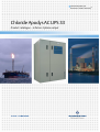
1
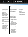
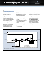
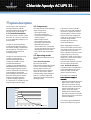
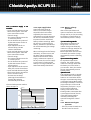
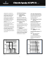
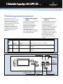
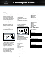
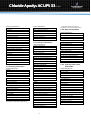
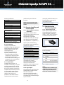
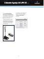
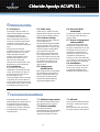
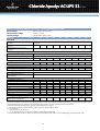
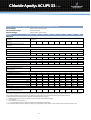
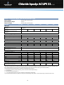
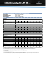
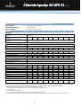
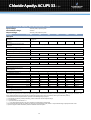
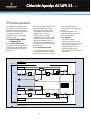
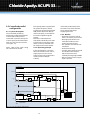
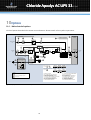
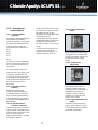
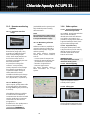
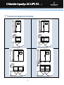
Industrial Power for
Business-Critical ContinuityTM
Chloride Apodys AC UPS 33
Product catalogue — 6 Pulses-3 phase output
Chloride Apodys AC UPS 33
Uninterruptible Power Supply System
3-phase input — 6 Pulses - 3-phase output
Scope
4
General requirements
4
Range overview
5
System description
6
Monitoring and control interfaces
9
Mechanical data
14
Environmental conditions
14
Technical data
15
Parallel operation
22
Options
24
General arrangement drawings
29
Chloride Apodys AC UPS 336P-3ph
1 Scope
2 General requirements
This document describes a
continuous duty three phase
Alternating Current (AC) input,
stand-alone, three phase AC
output Uninterruptible Power
System (UPS).
2.1. ISO certification
The Apodys AC UPS range meets
customers’ technical
specifications for industrial
applications such as Power
generation, Oil and gas offshore
developments (platforms, FPSO,
etc…), Oil and gas transportation
(pipelines…), Oil and Gas
treatment plants (refineries,
petrochemical units…), Railways
and undergrounds control and
signalling systems, etc...
The Apodys AC UPS range is part
of Chloride’s know-how and longtime relationship with industrial
businesses.
Chloride Industrial Power services
include:
• Consultancy services
• Pre-engineering design and
support
• Project Management (contract
management, detailed
engineering, documents for
approval, manufacturing,
product testing, witnesstesting if requested, shipment,
tailored user manual)
• Services (recommended
commissioning spare parts,
commissioning services,
product lifetime spare parts,
hotline, trainings, maintenance
contracts, LIFE.net remote
maintenance, etc…)
Chloride France S.A. is certified
by the British Standard Institution
(BSl), as a company with a total
quality and environmental
control system in accordance
with the ISO 9001 and ISO
14001.
•
•
•
2.2. Applied standards
The Apodys AC UPS range shall
have the CE mark in accordance
with the Safety and EMC
Directives 2006/95/EC and
2004/108/EC.
The Apodys AC UPS range is
designed and manufactured in
accordance with the following
international standards:
• IEC60146 Semi conductor
converters:
− IEC60146-1-1 specifications of
basic requirements
− IEC60146-1-3 transformers
and reactors
− IEC60146-2 self-commutated
semiconductor converters
including direct dc converters.
• IEC60950 Safety of information
technology equipment
including electrical business
equipment
• IEC60439 Low voltage
switchgear and control gear
assemblies
− IEC60439-1 Type-tested and
partially type-tested
assemblies
− IEC60439-2 Particular
requirements for busbar
trunking systems (busways)
− IEC 60439-3 Particular
requirements for LV
switchgear and control gear
assemblies intended to be
installed in places where
unskilled persons have access
4
•
for their use — distribution
boards
IEC60529 Degrees of
protection provided by
enclosures (IP Code)
IEC60726 Dry-type power
transformers
EN61000-6-2 Electromagnetic
compatibility (EMC) Generic
standards — Immunity for
industrial environments
IEC61000-6-4 Electromagnetic
compatibility (EMC) Generic
standards — Emission standard
for industrial environments.
Chloride Apodys AC UPS 336P-3ph
3 Range overview
The system described is a static
UPS system as shown in Figure 1.
The system operates on a
microprocessor-based thyristors
charger and microprocessorbased IGBTs inverter. By means
of digital vector control
technology the performance of
the UPS are enhanced. By adding
system components, such as
paralleling kits, safety and
disconnecting devices,
distribution cubicles, as well as
software and communications
solutions, it is possible to set up
elaborated systems ensuring
complete AC load protection.
The UPS uses today’s most
reliable topology: the double
conversion. It converts AC power
from an AC source in to DC power
to charge a battery and
reconverts it into AC power to
provide a clean and reliable AC
output to power the AC load.
3.1. The system
The UPS provides high quality AC
power for electronic equipment
loads. It offers the following
features:
• Increased AC power quality
• Full compatibility with all types
of loads
• Power blackout protection (for
systems associated with
battery)
• Lifetime of, at least, 20 years,
combined with an appropriate
preventive maintenance
• Operation temperature of 0 to
40°C permanent.
3.2. Models available
The Apodys AC UPS 3-ph range
includes several kVA ratings
output models as specified in
paragraph 8. It is of the threephase output type.
UPS cubicle
BYPASS SUPPLY
3Ph
-V21
Charger
-Q22
Inverter
-V18
AC SUPPLY
3Ph
-Q21
-Q3
-Q
AUTO
TRANSITION
TEST
MAINTENANCE
BATTERY
*
-F5
Battery
fuse
-Q3 : UPS INPUT ISOLATOR
-V18/V21 : STATIC SWITCH
-Q21 : BYPASS SWITCH
-Q24 : UPS OUTPUT ISOLATOR
Legend:
*
-Q24
-Q23
Interconnection cables not supplied by Chloride
Figure 1: APODYS AC UPS single line diagram
5
AC LOAD
3Ph
21 22 23
XX
X XX
XX
X
Chloride Apodys AC UPS 336P-3ph
4 System description
In this section, the main power
electronic features and the
operating modes of the Apodys
AC UPS range are described.
4.2. Components
4.1. General description
The three-phase current taken
from the AC source is converter
to a regulated DC voltage by a 6pulse rectifier.
In order to protect the power
components within the system,
the rectifier bridge is fused with a
fast acting fuse. A transformer is
provided at the input of the
rectifying bridge.
The DC current taken from the
rectifier is converted to a
sinusoidal and regulated AC
voltage by an IGBTs inverter
(Insulated Gate Bipolar
Transistor), using PWM (Pulse
Width Modulation). This means
that the digital signal processor
controls the IGBTs so that the DC
input voltage is divided into
pulsed voltage to generate a low
distortion sinewave AC output
voltage with good transient
response voltage regulation.
A transformer is provided at the
output of the inverter bridge.
The UPS consists of the following
major components:
• One input isolator
• One main transformer
• 6-Thyristors bridge rectifier /
battery charger
• IGBTs bridge inverter
• One output transformer
• Electronic static switches
• Manual bypass switch
• Two control units, each based
on one microprocessor and one
Digital Signal Processor-DSP
• One control and visualisation
unit
4.3. Operating modes
The Apodys AC UPS operates as
follow:
4.3.1. Normal operation
The critical AC load is
continuously supplied by the UPS
inverter. The rectifier-charger
derives power from the AC
source and converts it into DC
power for the inverter whilst
simultaneously maintaining the
battery in a fully charged and
optimum operational condition
(floating mode).
time (s)
1000
800
600
The inverter converts the DC
power into clean and regulated
AC power to supply the critical
load through the static transfer
switch. The power loading can
reach up to 105% of the inverter
nominal rating without
considering the inverter in
overload conditions.
While supplying the load, the
inverter and static switch control
unit monitors the reserve supply
signal and ensures that the
inverter bridge tracks the reserve
supply frequency. Thus, any
automatic transfer to the reserve
supply (e.g. when an overload is
detected) is frequency
synchronised and does not cause
an interruption to the load.
4.3.2. Overload operation
The UPS inverter is considered in
overload conditions when the
load is beyond 105% of the
inverter nominal rating.
Two cases are considered:
Case 1: Reserve supply is
available:
• Upon overload detection by the
UPS inverter (above 105% of
the inverter nominal rating),
the static switch automatically
transfers the load to reserve
supply. The static switch
automatically switches back
the load to inverter 10 seconds
after the UPS inverter is back to
normal conditions.
400
The reserve supply withstands
overload as shown on Figure 2.
200
100
110
120
130
140
150 Overload (in %)
Figure 2: Reserve supply overload withstanding curve
6
Chloride Apodys AC UPS 336P-3ph
Case 2: Reserve supply is not
available:
• Upon overload detection by the
UPS inverter (above 110% and
up to 125% of the inverter
nominal rating):
− The system initiates a timer for
a 10 minutes period.
− The AC load remains powered
by the UPS inverter for this 10
minutes period.
− Upon expiration of the 10
minutes delay, the UPS
inverter shuts down.
• Upon overload detection by the
UPS inverter (above 125% and
up to 150% of the inverter
nominal rating):
− The system initiates a timer for
a 1 minute period.
− The AC load remains powered
by the UPS inverter for this 1
minute period.
− Upon expiration of this minute
delay, the inverter shuts down.
• Upon overload detection by the
UPS inverter above 150% of the
inverter nominal rating:
− The UPS inverter keeps
powering the AC load for 5
seconds after which it
automatically shuts down.
4.3.3. Input supply failure
Upon fault of the input AC
source, the rectifier-charger
stops while the load remains
supplied by the UPS inverter.
Upon Mains input fault detection,
the inverter immediately draws
its power from the associated
battery without switching. While
the inverter is powered by the
battery, indication is provided of
the actual autonomy percentage
remaining.
When reaching the end of battery
autonomy, an alarm occurs and
the static switch immediately
switches the load onto reserve
supply, without interruption. If
for any reason, the reserve supply
is not present or faulty and the
battery is no longer available, the
UPS automatically shuts down.
This overload operation mode is
shown in Figure 3.
time (s)
10 min
100 s
1 min
10 s
5s
4.3.4. Battery recharge
operation
After an AC input failure and
upon its restoration, the rectifiercharger can be pre-set (according
to customer’s specification) to
automatically restart in 2 ways:
1) Timer Recharge Mode:
ode:
If the Mains input failure was
longer than 5 minutes, the
rectifier charger automatically
restarts in recharge mode for the
pre-set recharge time. If the
Mains input failure was less than
5 minutes, the rectifier-charger
automatically restarts in floating
mode.
2) Current Recharge Mode:
For any Mains input failure
duration, the rectifier-charger
restarts in recharge mode until
the battery current is below a
pre-set value. Then, the rectifiercharger automatically turns to
floating mode.
3) Boost mode
This operating mode is a specific
mode dedicated to vented type
batteries. It is used when boost
charge or commissioning charge
is requested. During Boost mode,
the voltage limitation is increased
(up to 2.65V per cell for a Lead
Acid battery and up to 1.7V per
cell for a Nickel Cadmium
battery). Restoration of the
Floating mode is automatic after
a preset typical time of 5 hours,
unless the Floating mode is
manually initiated by the
operator through the control
unit.
4.3.5. Maintenance bypass
operation
100
125
150
Overload (in %)
Figure 3: Apodys AC overload curve
7
• If for any reason the UPS has to
be taken out of service for
Chloride Apodys AC UPS 336P-3ph
maintenance or repair, the
Apodys UPS is provided with a
manual bypass switch. The
bypass switch enables a load
transfer to reserve supply
without power interruption for
the load. Bypass isolation is
then complete, all serviceable
components such as fuses,
power modules etc. are
isolated.
• The transfer/retransfer is based
on the make-before-break
principle in order to secure the
critical load: the
transfer/retransfer operation is
automatically accomplished by
paralleling and synchronising
the inverter output to the
reserve supply, before closing
or opening the bypass switch as
appropriate.
4.4. Electrical features
4.4.4. Over voltage protection
4.4.1. Total harmonic
distortion of input
voltage
The rectifier-charger of the UPS is
automatically turned off if the DC
voltage exceeds the maximum
value associated to its
operational status.
The maximum voltage THD
allowed on the rectifier input is
8% to guarantee the correct
operation of the system (either
from utility or from generator).
4.4.5. Output voltage harmonic
distortion
The inverter provides harmonic
neutralisation and filtering to
limit the total harmonic
distortion on the voltage to less
than 3% with a linear load. For
reference non-linear load (as
defined by EN62040-3) the total
harmonic distortion is limited to
less than 5%.
4.4.2. Rectifier current
limitation
The rectifier-charger current of
the UPS is limited to the nominal
value either in floating, charge
and boost mode.
4.4.3. Battery current
limitation
4.4.6. Inverter short-circuit
capacity
The battery current is limited to
0,1C (Pb) or 0,2C (NiCd) of the
associated battery, in floating or
charge modes. In Boost mode,
the battery current is limited to
0,05C (Pb) or 0,1C (NiCd).
The inverter short-circuit capacity
of Apodys UPS is detailed in
Figure 4.
4.4.7. Static Switch shortcircuit capacity
The electronic static switch is
capable of supporting the shortcircuit currents as shown on
Figure 5.
t (ms)
time
1s
5s
Ph-N
100 ms
100 ms
Ph-Ph
10 ms
3
2
1
1.35
1.9
2.2
11
4
3.15
In (A)
Figure 4: Apodys AC UPS 3-ph inverter short circuit
capacity
2
3
4
5
6
7
8
9
10 In (A)
Figure 5: Apodys AC UPS reserve supply short circuit
capacity
8
Chloride Apodys AC UPS 336P-3ph
5 Monitoring and control interfaces
The UPS incorporates the
necessary controls, instruments
and indicators to allow the
operator to monitor the system
status and performance and take
any appropriate action.
Furthermore, interfaces are
available upon request, which
allow extended monitoring and
control, as well as service
functions.
Symbol
5.1. Light emitting diodes
(LEDs)
5.2. Start and Stop push
buttons
The UPS includes 3 external Light
Emitting Diodes (LEDs) to
indicate the overall system
operation status as well as the
condition of the functional
blocks. LEDs operation is
described in Figure 6.
These LEDs shall interact with the
active mimic diagram displayed
on the graphical display.
The Start and Stop push buttons
are integrated into the mimic
panel board, and operate as
described on Figure 7.
The control incorporates a safety
feature to prevent inadvertent
operation yet still allow rapid
shutdown in the event of an
emergency. This is achieved by
pressing the “STOP” button for 2
seconds before the module
stops. « Charger OFF » or
« Inverter OFF » is displayed on
the LCD.
LED colour
Green
Description
UPS normal operation
Comments
Load supplied by inverter
Green
flashing
Orange
Load on reserve or on
battery
UPS warning
Load powered by reserve or by battery
Red
UPS fault
One or more subassembly are affected but not
stopped
Subassembly are faulty and stopped or manually
stopped
STOP
Figure 6: Apodys UPS— Light Emitting Diodes (LED) operation description
“System normal” LED
“Warning” LED
“Alarm” LED
STOP
C
UPS
OK
Navigation buttons:
Up and down (in menus)
Valid and Cancel (parameters)
Figure 7: Apodys AC UPS — Local human-machine interface.
9
“Charger ON/OFF”
Push button
“Inverter
ON/OFF”
Push button
Inverter
Reset audible alarm
Push button
(Until a new alarm occurs)
Chloride Apodys AC UPS 336P-3ph
5.3. Display
5.3.2. Active mimic diagram
A graphical (64 x 128 pixels)
illuminated Liquid Crystal Display
(LCD) is provided to enable the
operating parameters, all the
measurements and the active
mimic diagram of the UPS to be
monitored. The LCD messages
are accessed by navigation
buttons (see Figure 7). The text is
available in English, unless
otherwise mentioned.
The active mimic diagram
displays the following
information:
• Graphical view of the
connected load
• Graphical view of the power
flow
• Graphical view of the status of
each functional block
The Figure 9 provides an example
of an active mimic situation:
• AC Mains input failure
• Rectifier-charger stopped
• Battery discharging
• AC load still supplied by reserve
By using the appropriate pushbuttons it is possible to display
the information described
hereafter.
The default page displays the
active mimic diagram of the UPS
(see Figure 8).
Status indications:
Figure 9: Active mimic panel, example of
situation
5.3.3. General menu
By pressing the “OK”, “UP”, or
“DOWN” buttons, the user enters
the general menu. If the user is
navigating in the menus, he may
return to the active mimic
diagram by pressing the “C”
button.
If the user does not request any
action (such as pressing a button)
for 5 minutes while displaying the
menus, the system will
automatically return to the
display of the default page active
mimic diagram.
By using these menus, the user
can access to detailed
information about each following
component:
• Rectifier-charger
• Battery
• Inverter
• Reserve supply
• AC Load
5.3.5. Rectifier-charger
information
5.3.1. Default page
Figure 8: mimic default page.
menu to provide the user with
detailed information, such as:
• Block status
• Block measures
• Block faults
• Block warnings
Pressing any key from the default
page (active mimic diagram)
allows the user to access to the
following general menu:
• Charger
• Battery
• Inverter
• Reserve supply
• AC load
• Reset
• Black Start (option)
• Event log
• Display setting
• Contact
5.3.4. Menus of functional
blocks
Each functional block (charger,
battery, inverter, reserve static
switch, load) includes its own
10
Charger off
Initialisation
Charger Stop
Equalisation mode*
Equalisation imposed*
Floating mode
Battery test mode*
Battery test imposed*
Boost mode*
Measurements indications:
UDC (charger output voltage)
IDC (charger output current)
U12 (Input voltage ph 1 and 2)
U23 (Input voltage ph 2 and 3)
U31 (Input voltage ph 3 and 1)
I1 (input line current)
I2 (input line current)
I3 (input line current)
Freq (input frequency)
Number of Mains failures
* Optional messages (according to
specification and system configuration)
Chloride Apodys AC UPS 336P-3ph
Warning indications:
Faults indications:
Test mode
Fan failure*
DC voltage low
Overload inhibit
Charger in current limit
Customised message 1*
Customised message 2*
Customised message 3*
No fault
Battery test fault memorised
End of discharge
Battery protection opened*
Customised message 1*
Customised message 2*
Customised message 3*
Fault indications:
5.3.7. Inverter information
No fault
High DC voltage
High DC voltage memorised
Too high I battery memorised
Charger fuse blown
Input protection opened
Charger off
Remote switch off*
AC supply fault
Customised message 1*
Customised message 2*
Customised message 3*
5.3.6. Battery information
Status indications:
Normal
Discharging
Charging
Fault or warning
Measurements indications:
Battery voltage
Battery current
Battery temperature
Battery autonomy (%)
Warnings indications:
DC earth fault*
Battery begin discharge
Imminent shutdown
Temp sensor fault memorised*
Warning BMS*
Customised message 1*
Customised message 2*
Customised message 3*
* Optional messages (according to
specification and system configuration)
* Optional messages (according to
specification and system configuration)
5.3.8. Reserve information
Status indications:
No warning; no fault
Warning; no fault
No warning; fault
Warning + fault
Measurements indications:
Status indications:
Inverter synchronised
Inverter on crystal
Inverter not running
Waiting for stop (only in parallel)*
Inverter switched off
Measurements indications:
UDC (inverter input voltage)
U1 (inverter output voltage ph1-N)
U2 (inverter output voltage ph2-N)
U3 (inverter output voltage ph3-N)
Inverter frequency (output frequency)
Warning indications:
No warning
Commissioning
Software time out
Fan failure*
Inverter overload warning
Customised message 1*
Customised message 2*
Customised message 3*
Fault indications:
No fault
Inverter switched off
VCE bridge fault memorised
Inverter overload fault memorised
Over temperature fault memorised
Low DC voltage
Repeated low DC voltage memorised
High DC voltage memorised
Microcontroller fault memorised
High AC voltage memorised
Frequency fault memorised
Parallel communication fault memorised*
Low AC voltage memorised*
Customised message 2*
Customised message 3*
11
Reserve voltage U1-N
Reserve voltage U2-N
Reserve voltage U3-N
Reserve frequency
Warnings indications available:
Reserve voltage fault
Reserve frequency fault
Reserve inhibited
Parallel reserve fault memorised*
Customised warning message 1*
Customised warning message 2*
Customised warning message 3*
5.3.9. Load and static switch
information
Status indications:
Load on inverter
Load on reserve
Manual bypass on
Load not supplied
Measurements indications:
Load voltage U1-N
Load voltage U2-N
Load voltage U3-N
Load current I1
Load current I2
Load current I3
Load frequency
Load power Ph1 (in kVA)
Load power Ph2 (in kVA)
Load power Ph3 (in kVA)
Load power Ph1 (in kW)
Load power Ph2 (in kW)
Load power Ph3 (in kW)
Total time on inverter
Load current ratio (%)
Chloride Apodys AC UPS 336P-3ph
Warning indications:
No warning
AC earth fault*
Manual bypass closed
Static switch overload
Customised message 1*
Customised message 2*
Customised message 3*
Fault indications:
No fault
Emergency power off*
Static switch overload fault memorised
Inverter static switch fault memorised
Reserve static switch fault memorised
Static switch hardware fault memorised
AC output voltage fault*
Customised load fault message 2*
Customised load fault message 3*
* Optional messages (according to
specification and system configuration)
5.3.10. Event log
The Event Log function is
available through the display and
allows memorising each event
into the historical record, in a
chronological way.
The Event Log function can
operate in 2 different ways:
• Saturable mode: It records a
maximum of 100 events after
the first event appearance.
• FIFO mode: After recording 100
events, the 101st event deletes
the 2nd one and so on.
5.3.11. Black Start
The Black Start function, as
available in the display, is only for
paralleled UPS systems. It allows
starting parallel inverters even if
the reserve supply is not present.
The Black Start function operates
as follow: When 2 UPS systems
are paralleled and the reserve
supply is not present, it is
possible to start both inverters
simultaneously via the control
panel of only one of the two
inverters.
Among all possible function, the
following logic inputs can be
wired upon request:
NOTE: This function differs from
the one described in the Options
section.
5.4. Remote signalling and
control signal
5.4.1. Logic outputs for remote
indications
Apodys UPS is able to deliver
several output information. Upon
request, these output
information can be made
available on double-pole changeover (dpco) contacts (8A/250V
AC1; 8A/30V DC1; 1A/60V DC1).
Remote control on/off
Emergency power off
5.5. Communication
interfaces (options)
5.5.1. Isolated RS 232 link
Upon request, Apodys UPS can
be equipped with one sub-D 9
points connector for direct (1
master, 1 slave, max 15 meters)
serial RS232 communication.
Shield
54
9 32
87 1
6
Upon request, the following
information is made available on
voltage-free contacts:
UPS general alarm
Charger fault
Inverter fault
Reserve supply fault
Load on reserve
Imminent shutdown
Customised message 1
Customised message 2
Customised message 3
When information is requested
on voltage-free contact,
connection of the customer
cables is achieved on the
identified, screw-clamp terminal
blocks of each relay-holder.
5.4.2. Logic inputs
The Apodys UPS range allows the
signalisation of specific alarms
from the customer’s
environment and eventually
takes the appropriate action on
the UPS thanks to dedicated logic
inputs available.
12
Figure 10: RS 232 SubD 9 points
connector
Pin assignment is described in the
Table 1 hereafter.
Pin
1
2
3
4
5
6
7
8
9
Signal
Not used
Tx
Rx
Not used
RS232
GND
Not used
RTS
Not used
Not used
Explanation
Transmission RS232
Reception RS232
Signal ground
Clear to send RS232
Table 1: RS232 pin assignment
NOTE:
If simultaneous use of RS232 port
and RS 485 is necessary, this will
require 2 separate PCB, one for
RS232 and the other for RS485.
Chloride Apodys AC UPS 336P-3ph
5.5.2. Isolated RS 485 link
Upon request, Apodys UPS can
be equipped with 6 points socket
for multipoint (1 master, up to 31
slaves, max 1300 meters) serial
RS485 communication.
Customer connection is easily
achieved thanks to the screwclamp connector provided (see
figure below). Earth connection is
achieved on the PCB through a
6.35 Faston lug.
The RS485 communication path
may be used either in 4 wires
mode or in 2 wires mode, as
described in the Table 2
hereafter.
Pin Signal
4-wires mode
1
GND
Not used
2
Tx-
3
Tx+
4
Rx-
5
Rx+
6
+5V
Transmission
RS485/ neg.
Transmission
RS485/ pos.
Reception
RS485/ neg.
Reception
RS485/ pos.
Not used
Table 2: RS 485 pin assignment
12
34
5
6
Figure 11: RS 485 6 points connector
13
2-wires
mode
Not used
Negative
signal
Positive
signal
Not used
Not used
Not used
Chloride Apodys AC UPS 336P-3ph
6 Mechanical data
6.1. Enclosure
6.3. Cable entry
The Apodys UPS is housed in a
space-saving modular enclosure
including front doors and
removable panels (standard
external protection IP 20). The
enclosure is made of sheet steel.
The doors can be locked. The
enclosure is of the floor mounted
type.
For harsh environmental
conditions (dust, water), a higher
degree of protection, of up to
IP42 is available in option.
Specific system design can be
achieved up to IP54. In such
extreme cases, technical
characteristics mentioned in this
document are not maintained.
Cable entry is achieved via the
bottom of the cabinet. Top cable
entry is also available in option.
6.2. Ventilation
6.5. Components
identification
Fan-assisted air cooling is
standard on the Apodys AC UPS
range. The cooling air entry is in
the base and the air exit at the
top of the device. It is
recommended that the enclosure
is installed with at least 400 mm
of free space between device and
ceiling at the top in order to allow
an unhindered cooling air exit.
6.4. Enclosure design
All the surfaces of the enclosure
are finished with an
electrostatically applied powderepoxy-polyester coat, cured at
high temperature. Colour of the
enclosure is RAL 7032 (pebble
grey) textured semi-gloss.
For uniformity of the UPS with
other equipments in electrical
rooms, the surface finishing and
the colour of the enclosure may
be available according to the
customer’s specification and
upon request.
Main components are identified
by self-adhesive vinyl labels. In
option, Apodys UPS offers the
possibility to include specific
component identification by
engraved traffolyte labels.
6.6. Internal cables
connection
Connection of cables is achieved
by inserting cables directly in
screw-clamps.
6.7. Access to integrated
subassemblies
All internal subassemblies are
accessible for typical and most
frequent maintenance from the
front of the unit. Top access is
available for replacement of
cooling fans. Rear access is not
required for installation or
servicing. In any case and if side
or rear access is required, the side
and rear panels are removable.
6.8. Installation
The UPS is forkliftable from the
front. Upon request, it can be
equipped with lifting lugs to
facilitate its installation on site.
7 Environmental conditions
The Apodys UPS is capable of
withstanding any combination of
the following environmental
conditions. It operates without
mechanical or electrical damage
or degradation of operating
characteristics.
7.1. Ambient temperature
7.3. Altitude
The UPS is capable of operating
permanently from 0° to 40°C.
The maximum altitude without
derating is 1000 metres above
sea level.
Please consult us for operating
the system above 1000 metres.
7.2. Relative humidity
The UPS is capable of
withstanding up to 90% humidity
level (non-condensing) for an
ambient temperature of 20°C.
14
Chloride Apodys AC UPS 336P-3ph
8 Technical data
Data common to the complete Apodys AC UPS 31 range
Rectifier input
Nominal input voltage
Input phases
Input voltage tolerance
Nominal frequency
Tolerance on frequency
Rectifier type
soft start
Isolation transformer
Maximum recommended voltage distortion (THD) from Mains (or
generator) on the input of the rectifier
(V)
(%)
(Hz)
(%)
(s)
(%)
400 [380 / 415]
3 ph + N
+10 / -10
50 / 60 (factory setting selectable)
+5 / -5
6-pulses SCR (thyristors)
5
Standard
8
Rectifier output
DC voltage stability
DC voltage ripple in float (disconnected battery)
Rectifier-charger current limitation (in floating, charge or boost)
(%)
(% rms)
< +/- 1
1
I nominal
Inverter output
Nominal output voltage
Nominal output frequency
Overload at cos phi = 0.8
Short circuit capacity
Isolating transformer
Voltage stability (for 100% load variation):
Static
Dynamic
Frequency response
Frequency stability:
with own oscillator
with reserve supply synchronisation
Harmonic voltage distortion:
with 100% linear load
with 100% non linear load
Output crest factor admissible
Load power factor
(Hz)
(%)
(%)
(%)
(%)
(Hz/s)
See tables on the following pages
50 / 60 [factory setting selectable]
125 (10 min) / 150 (1 min)
315 (100 ms) / 220 (5 s)
Standard on the complete range
+/- 1
Complies with IEC/EN 62040-3, class 1
0.1
(%)
(%)
+/- 0.05
+/- 4 [adjustable from 1.2 to 6]
(%)
(%)
<3
Complies with IEC 62040-1-2
3/1
0.5 lag to 0.5 lead
(V)
(%)
(Hz)
(%)
See tables on the following pages
+/- 10 [adjustable from +/-5% to +/-20%]
50 / 60 [factory setting selectable]
+/- 3 [adjustable from +/-0.2% to +/-5%]
Reserve supply input
Reserve input voltage
Reserve input voltage tolerance
Reserve input frequency
Reserve input frequency tolerance
System data
External protection degree
Internal protection degree
Cable entry
Access
System design life
(years)
IP 20
IP 20
Bottom
Front
20
Environmental data
Operating temperature
Storage temperature
Maximum relative humidity (non condensing)
Operating altitude
(°C)
(°C)
(%)
15
0 to 40 (permanent operation)
-20 to +70
<90
1000 m (without system derating)
Chloride Apodys AC UPS 336P-3ph
Data for 3 x 400 VAC output / 120 VDC (110 VDC) intermediate circuit
Input voltage:
Intermediate voltage:
Output voltage:
Ratings
400 VAC [380, 415] three phase
120 VDC [110 VDC]
400 VAC [380, 415] three phase
(kVA)
5
7.5
10
15
20
25
30
40
50
29
45
70
70
90
112
140
UPS input
Nominal input voltage, frequency,
tolerances
Maximum current consumption at
full load (°)
Recommended type for UPS input
protection
See page 15
(A)
14
23
D curve (circuit breakers) or gL (fuses)
Rectifier-charger output
Nominal voltage
(V)
120
Output voltage in floating
(V)
136.2
Max DC current
(A)
50
80
100
160
250
250
320
400
500
(W)
4762
7143
9524
14118
18823
23529
28235
37647
46512
(V)
(A)
400 [380, 415] — 3-phase + neutral
7
11
14
22
29
36
43
58
72
(V)
400 [380, 415] — 3-phase + neutral
Battery
Battery output power
UPS output
Nominal output voltage AC
Nominal output current(*)
Reserve static switch
Nominal voltage AC
Recommended type for reserve
input protection
D curve (circuit breakers) or gL (fuses)
UPS System data
Heat dissipation system(**)
UPS system losses(*)
UPS system efficiency(***)
UPS system noise
Height
Width
Depth
Footprint
Mass(****)
(W)
(%)
(dBA)
(mm)
(mm)
(mm)
(m²)
(kg)
F
1291
74
62
1852
800
808
0.64
360
F
1937
75
62
1852
800
808
0.64
400
F
2582
76
62
1852
800
808
0.64
440
F
3514
76
70
1852
1200
808
0.96
540
F
4460
78
70
1852
1200
808
0.96
650
F
5575
78
71
1852
1200
808
0.96
720
F
6691
78
71
1852
1200
808
0.96
780
F
8921
78
71
1852
1200
808
0.96
870
F
10556
79
73
1852
1600
808
1.28
990
B0
B0
B0
C0
C0
C0
C0
C0
E0
Drawing (See paragraph 11)
Code for general arrangement
NOTA:
-These data are typical and are valid in the following conditions: Sealed lead acid battery (60 cells) operated at Ufloat=2,27V per cell and at 20°C, with
a 3x400VAC Mains input. The system can also be designed and pre-set for use with any other type of stationary battery.
-Full customized technical specification is provided at the bidding stage of project.
-(*) at full load (cos phi 0.8), battery in floating, and at 3x400 VAC nominal output voltage.
-(**) F: Fan cooling.
-(***) For tolerance, see IEC 60146-1-1
-(****) For information only. Mass may vary according to configurations and options
-(°) at inverter full load (cos phi 0.8), battery in recharge, low input voltage level (400Vac -10%) and with charger input power factor 0.85.
16
Chloride Apodys AC UPS 336P-3ph
Data for 3 x 400 VAC output / 240 VDC (220 VDC) intermediate circuit
Input voltage:
Intermediate voltage:
Output voltage:
Ratings
400 VAC [380, 415] three phase
240 VDC [220 VDC]
400 VAC [380, 415] three phase
(kVA)
15
20
25
30
40
50
60
80
100
65
83
104
130
165
206
257
UPS input
Nominal input voltage, frequency,
tolerances
Maximum current consumption at
full load (°)
Recommended type for UPS input
protection
See page 15
(A)
42
53
D curve (circuit breakers) or gL (fuses)
Rectifier-charger output
Nominal voltage
(V)
225
Output voltage in floating
(V)
258.8
Max DC current
(A)
80
100
125
160
200
250
320
400
500
18605
22988
27586
36782
45977
54545
71111
87912
58
72
87
116
144
Battery
Battery output power
(kW) 13953
UPS output
Nominal output voltage AC
Nominal output current(*)
(V)
(A)
400 [380, 415] — 3-phase + neutral
22
29
36
43
(V)
400 [380, 415] — 3-phase + neutral
Reserve static switch
Nominal voltage AC
Recommended type for reserve
input protection
D curve (circuit breakers) or gL (fuses)
UPS System data
Heat dissipation system(**)
UPS system losses(*)
UPS system efficiency(***)
UPS system noise
Height
Width
Depth
Footprint
Mass(****)
(W)
(%)
(dBA)
(mm)
(mm)
(mm)
(m²)
(kg)
F
3004
80
63
1852
800
808
0.64
500
F
4005
80
64
1852
800
808
0.64
565
F
4456
81
65
1852
800
808
0.64
625
F
5347
82
68
1852
800
808
0.64
695
F
7129
82
70
1852
1200
808
0.96
835
F
8912
82
71
1852
1200
808
0.96
930
F
9416
84
71
1852
1600
808
1.28
1000
F
10854
86
73
1852
1600
808
1.28
1230
F
12539
86
73
1852
1600
808
1.28
1380
B0
B0
B0
B0
C0
C0
E0
E0
E0
Drawing (See paragraph 11)
Code for general arrangement
NOTA:
-These data are typical and are valid in the following conditions: Sealed lead acid battery (114 cells) operated at Ufloat=2,27V per cell and at 20°C,
with a 3x400VAC Mains input. The system can also be designed and pre-set for use with any other type of stationary battery.
-Full customized technical specification is provided at the bidding stage of project.
-(*) at full load (cos phi 0.8), battery in floating, and at 3x400 VAC nominal output voltage
-(**) F: Fan cooling
-(***) For tolerance, see IEC 60146-1-1
-(****) For information only. Mass may vary according to configurations and options
-(°) at inverter full load (cos phi 0.8), battery in recharge, low input voltage level (400Vac -10%) and with charger input power factor 0.85.
17
Chloride Apodys AC UPS 336P-3ph
Data for 3 x 400 VAC output / 400 VDC intermediate circuit
Input voltage:
Intermediate voltage:
Output voltage:
Ratings
400 VAC [380, 415] three phase
400 VDC
400 VAC [380, 415] three phase
(kVA)
40
50
60
80
100
120
140
175
216
277
343
UPS input
Nominal input voltage, frequency,
tolerances
Maximum current consumption at
full load (°)
Recommended type for UPS input
protection
See page 15
(A)
109
D curve (circuit breakers) or gL (fuses)
Rectifier-charger output
Nominal voltage
(V)
384
Output voltage in floating
(V)
435.8
Max DC current
(A)
125
160
200
250
320
400
43478
52174
69565
86956
104348
116
144
173
Battery
Battery output power
(kW) 35165
UPS output
Nominal output voltage AC
Nominal output current(*)
(V)
(A)
400 [380, 415] — 3-phase + neutral
58
72
87
(V)
400 [380, 415] — 3-phase + neutral
Reserve static switch
Nominal voltage AC
Recommended type for reserve
input protection
D curve (circuit breakers) or gL (fuses)
UPS System data
Heat dissipation system(**)
UPS system losses(*)
UPS system efficiency(***)
UPS system noise
Height
Width
Depth
Footprint
Mass(****)
(W)
(%)
(dBA)
(mm)
(mm)
(mm)
(m²)
(kg)
F
5409
86
70
1852
1200
808
0.96
810
F
6253
86
71
1852
1200
808
0.96
925
F
7504
86
73
1852
1600
808
1.28
1100
F
9227
87
73
1852
1600
808
1.28
1250
F
11533
87
73
1852
1600
808
1.28
1390
F
12696
88
74
1852
1600
1008
1.60
1560
C0
C0
E0
E0
E0
F0
Drawing (See paragraph 11)
Code for general arrangement
NOTA:
-These data are typical and are valid in the following conditions: Sealed lead acid battery (192 cells) operated at Ufloat=2,27V per cell and at 20°C,
with a 3x400VAC Mains input. The system can also be designed and pre-set for use with any other type of stationary battery.
-Full customized technical specification is provided at the bidding stage of project.
-(*) at full load (cos phi 0.8), battery in floating, and at 3x400 VAC nominal output voltage.
-(**) F: Fan cooling.
-(***) For tolerance, see IEC 60146-1-1
-(****) For information only. Mass may vary according to configurations and options
-(°) at inverter full load (cos phi 0.8), battery in recharge, low input voltage level (400Vac -10%) and with charger input power factor 0.85.
18
Chloride Apodys AC UPS 336P-3ph
Data for 3 x 220 VAC output / 120 VDC (110 VDC) intermediate circuit
Input voltage:
Intermediate voltage:
Output voltage:
Ratings
400 VAC [380, 415] three phase
120 VDC [110 VDC]
220 VAC [190, 208] three phase
(kVA)
5
7.5
10
15
20
25
30
40
50
29
45
70
70
89
112
140
UPS input
Nominal input voltage, frequency,
tolerances
Maximum current consumption at
full load (°)
Recommended type for UPS input
protection
See page 15
(A)
14
23
D curve (circuit breakers) or gL (fuses)
Rectifier-charger output
Nominal voltage
(V)
120
Output voltage in floating
(V)
136.2
Max DC current
(A)
50
80
100
160
250
250
320
400
500
7143
9524
14118
18823
23529
28235
37647
46512
52
66
79
105
131
Battery
Battery output power
(kW) 4762
UPS output
Nominal output voltage AC
Nominal output current(*)
(V)
(A)
220 [190, 208] — 3-phase + neutral
13
20
26
39
(V)
220 [190, 208] — 3-phase + neutral
Reserve static switch
Nominal voltage AC
Recommended type for reserve
input protection
D curve (circuit breakers) or gL (fuses)
UPS System data
Heat dissipation system(**)
UPS system losses(*)
UPS system efficiency(***)
UPS system noise
Height
Width
Depth
Footprint
Mass(****)
(W)
(%)
(dBA)
(mm)
(mm)
(mm)
(m²)
(kg)
F
1291
74
61
1852
800
808
0.64
365
F
1937
75
62
1852
800
808
0.64
410
F
2582
76
62
1852
800
808
0.64
445
F
3514
76
68
1852
1200
808
0.96
540
F
4460
78
70
1852
1200
808
0.96
655
F
5575
78
70
1852
1200
808
0.96
730
F
6691
78
71
1852
1200
808
0.96
790
F
8921
78
71
1852
1200
808
0.96
875
F
10556
79
73
1852
1600
808
1.28
995
B0
B0
B0
C0
C0
C0
C0
C0
E0
Drawing (See paragraph 11)
Code for general arrangement
NOTA:
-These data are typical and are valid in the following conditions: Sealed lead acid battery (114 cells) operated at Ufloat=2,27V per cell and at 20°C,
with a 3x400VAC Mains input. The system can also be designed and pre-set for use with any other type of stationary battery.
-Full customized technical specification is provided at the bidding stage of project.
-(*) at full load (cos phi 0.8), battery in floating, and at 3x220 VAC nominal output voltage.
-(**) F: Fan cooling.
-(***) For tolerance, see IEC 60146-1-1
-(****) For information only. Mass may vary according to configurations and options
-(°) at inverter full load (cos phi 0.8), battery in recharge, low input voltage level (400Vac -10%) and with charger input power factor 0.85.
19
Chloride Apodys AC UPS 336P-3ph
Data for 3 x 220 VAC output / 240 VDC (220 VDC) intermediate circuit
Input voltage:
Intermediate voltage:
Output voltage:
Ratings
400 VAC [380, 415] three phase
240 VDC [220 VDC]
220 VAC [190, 208] three phase
(kVA)
15
20
25
30
40
50
60
80
100
66
83
104
130
165
206
257
UPS input
Nominal input voltage, frequency,
tolerances
Maximum current consumption at
full load (°)
Recommended type for UPS input
protection
See page 15
(A)
43
53
D curve (circuit breakers) or gL (fuses)
Rectifier-charger output
Nominal voltage
(V)
225
Output voltage in floating
(V)
258.8
Max DC current
(A)
80
100
125
160
200
250
320
400
500
18605
22988
27586
36782
45977
54545
71111
87912
105
131
157
210
262
Battery
Battery output power
(kW) 13953
UPS output
Nominal output voltage AC
Nominal output current(*)
(V)
(A)
220 [190, 208] — 3-phase + neutral
39
52
66
79
(V)
220 [190, 208] — 3-phase + neutral
Reserve static switch
Nominal voltage AC
Recommended type for reserve
input protection
D curve (circuit breakers) or gL (fuses)
UPS System data
Heat dissipation system(**)
UPS system losses(*)
UPS system efficiency(***)
UPS system noise
Height
Width
Depth
Footprint
Mass(****)
(W)
(%)
(dBA)
(mm)
(mm)
(mm)
(m²)
(kg)
F
3167
80
63
1852
800
808
0.64
505
F
4005
80
64
1852
800
808
0.64
570
F
4719
80
65
1852
800
808
0.64
630
F
5347
82
68
1852
800
808
0.64
700
F
7129
82
70
1852
1200
808
0.96
840
F
8912
82
71
1852
1200
808
0.96
940
F
9416
84
71
1852
1600
808
1.28
1010
F
10854
86
73
1852
1600
808
1.28
1240
F
12539
86
73
1852
1600
808
1.28
1405
B0
B0
B0
B0
C0
C0
E0
E0
E0
Drawing (See paragraph 11)
Code for general arrangement
NOTA:
-These data are typical and are valid in the following conditions: Sealed lead acid battery (114 cells) operated at Ufloat=2,27V per cell and at 20°C,
with a 3x400VAC Mains input. The system can also be designed and pre-set for use with any other type of stationary battery.
-Full customized technical specification is provided at the bidding stage of project.
-(*) at full load (cos phi 0.8), battery in floating, and at 3x220 VAC nominal output voltage
-(**) F: Fan cooling
-(***) For tolerance, see IEC 60146-1-1
-(****) For information only. Mass may vary according to configurations and options
-(°) at inverter full load (cos phi 0.8), battery in recharge, low input voltage level (400Vac -10%) and with charger input power factor 0.85.
20
Chloride Apodys AC UPS 336P-3ph
Data for 3 x 220 VAC output / 400 VDC intermediate circuit
Input voltage:
Intermediate voltage:
Output voltage:
Ratings
400 VAC [380, 415] three phase
400 VDC
220 VAC [190, 208] three phase
(kVA)
40
50
60
80
100
120
140
175
216
277
343
UPS input
Nominal input voltage, frequency,
tolerances
Maximum current consumption at
full load (°)
Recommended type for UPS input
protection
See page 15
(A)
109
D curve (circuit breakers) or gL (fuses)
Rectifier-charger output
Nominal voltage
(V)
384
Output voltage in floating
(V)
435.8
Max DC current
(A)
125
160
200
250
320
400
43478
52174
69565
86956
104348
210
262
315
Battery
Battery output power
(kW) 35165
UPS output
Nominal output voltage AC
Nominal output current(*)
(V)
(A)
220 [190, 208] — 3-phase + neutral
105
131
157
(V)
220 [190, 208] — 3-phase + neutral
Reserve static switch
Nominal voltage AC
Recommended type for reserve
input protection
D curve (circuit breakers) or gL (fuses)
UPS System data
Heat dissipation system(**)
UPS system losses(*)
UPS system efficiency(***)
UPS system noise
Height
Width
Depth
Footprint
Mass(****)
(W)
(%)
(dBA)
(mm)
(mm)
(mm)
(m²)
(kg)
F
5409
86
70
1852
1200
808
0.96
815
F
6253
86
71
1852
1200
808
0.96
930
F
7504
86
73
1852
1600
808
1.28
1110
F
9227
87
73
1852
1600
808
1.28
1260
F
11533
87
73
1852
1600
808
1.28
1415
F
12696
88
74
1852(°°)
1600(°°)
1008(°°)
1.60(°°)
1590(°°)
C0
C0
E0
E0
E0
F0(°°)
Drawing (See paragraph 11)
Code for general arrangement
NOTA:
-These data are typical and are valid in the following conditions: Sealed lead acid battery (192 cells) operated at Ufloat=2,27V per cell and at 20°C,
with a 3x400VAC Mains input. The system can also be designed and pre-set for use with any other type of stationary battery.
-Full customized technical specification is provided at the bidding stage of project.
-(*) at full load (cos phi 0.8), battery in floating, and at 3x220 VAC nominal output voltage
-(**) F: Fan cooling
-(***) For tolerance, see IEC 60146-1-1
-(****) For information only. Mass may vary according to configurations and options
-(°) at inverter full load (cos phi 0.8), battery in recharge, low input voltage level (400Vac -10%) and with charger input power factor 0.85
-(°°) external bypass cabinet mandatory and not included in this description.
21
Chloride Apodys AC UPS 336P-3ph
9 Parallel operation
The Apodys UPS systems have
the capability to be connected in
parallel for Dual configurations
between units of the same rating.
The parallel connection of
Apodys UPS increases reliability
for the AC load.
Each Apodys UPS is supplied with
the parallel kit option, which
consists in one printed circuit
board POB (Parallel Operation
Board) and one 25 poles,
screened data line to the
neighbouring UPS system. A dual
parallel system is controlled and
monitored automatically by
controlling each individual UPS.
All reserve lines and UPS included
share the load.
9.1. Distributed parallel
configuration
9.1.1. System description
The Apodys UPS range is capable
of operating in Dual distributed
parallel configuration as shown
on Figure 12.
If one of the UPS fails, the
remaining UPS keeps supplying
the load.
In such configuration, the
paralleled UPSs must share the
same reserve supply.
9.1.3. Benefits
• Very simple system
• Thanks to the vector control,
there is no master and no slave.
• No single point of failure as
each UPS includes its own
parallel operation board
• The available overload current
is doubled
9.1.2. Operating principle
In this configuration, the 2 UPSs
are connected in parallel so that
they continuously share the load.
Bypass cabinet 1
BYPASS SUPPLY
3Ph
UPS 1 cabinet
APODYS
DISPLAY
-Q21-1
U,F
U,I , F
U,I
U,F
CHARGER 1
C
INVERTER 1
-Q3-1
-Q5-1
B
U , F,I , W
U
AC SUPPLY 1
3Ph
-Q24-1
A
AC LOAD
3ph
I
*
BATTERY 1
-Q21
Contact
A B C
Position
1 0 1
AUTO
TRANSITION 1 0 1
0 1 1
TEST
MAINTENANCE 0 1 0
-Q5-2
*
BATTERY 2
I
BYPASS SWITCH OPERATION
UPS 2 cabinet
APODYS
DISPLAY
U,I
U,I , F
U,F
INVERTER 2
CHARGER 2
U
-Q3-2
U, F ,I , W
-Q21-2
AC SUPPLY 2
3Ph
A
B
U,F
C
Bypass cabinet 2
BYPASS SUPPLY
3Ph
Legend:
*
Interconnection cables not supplied by Chloride
Figure 12: Distributed parallel configuration
22
-Q24-2
Chloride Apodys AC UPS 336P-3ph
Each Apodys UPS is supplied with
the parallel kit option, which
includes one printed circuit board
POB (Parallel Operation Board)
and one 25 poles, screened data
line to the neighbouring UPS
system.
Each UPS is monitored and
controlled individually. Each UPS
includes only one inverter static
switch, which is paralleled with
the single reserve static switch.
9.2. Centralised parallel
configuration
9.2.1. System description
The centralised paralleling
philosophy enables UPSs without
reserve static switches to be
connected in parallel. Hereby the
reserve supply to the loads works
with one central reserve cubicle
(see Figure 13).
Again, UPSs of the same rating
are connected in parallel.
All the UPS continuously share
the load. If one of the UPS fails,
the remaining UPS keeps
supplying the load.
9.2.3. Benefits
• Thanks to the vector control,
there is no master and no slave.
• No single point of failure as
each UPS includes its own
parallel operation board
• The available overload current
is doubled
• Perfect load sharing
• 3 simple static switches instead
of 2 double static switches,
which increases overall
reliability through higher MTBF
• Only one single reserve supply
input is present.
9.2.2. Operating principle
In this configuration, each UPS
does not include its own reserve
supply anymore. The reserve
supply is externally centralised in
a COC (Common Output
Cubicle).
Bypass cabinet
BYPASS SUPPLY
3Ph
UPS1 cabinet
DISPLAY
U, I, F
U, I
U
U, F
CHARGER 1
U
INVERTER 1
AC SUPPLY 1
3Ph
I
*
BATTERY 1
U, F
U, F
C
B
*
BATTERY 2
U, F, I, W
A
AC LOAD
3Ph
I
U, F, I, W
Contact
UPS2 cabinet
DISPLAY
U, I, F
U, I
U, F
U
CHARGER 2
U
AC SUPPLY 2
3Ph
*
Interconnection cables not
supplied by Chloride
Figure 13: Centralised parallel configuration
23
INVERTER 2
Position
AUTO
TRANSITION
TEST
MAINTENANCE
A
B
C
1
0
1
1
0
1
0
1
1
0
1
0
BYPASS SWITCH OPERATION
Chloride Apodys AC UPS 336P-3ph
10 Options
10.1. Main electrical options
The list of options described in this section is non-exhaustive. Please consult us for any other requirement.
Distribution
cubicle
8
UPS cubicle
2
3
4
5
Physical segregation
7
U31
-T31
-Q31
-Q34
BYPASS SUPPLY
3Ph
DISPLAY
1
U, I, F
U, I
I
U
U, F
6
-T11
U, F, I, W
-V18
AC Distribution
-Q21
-Q24
-Q23
AC SUPPLY
3Ph
-K10
Shunt
trip
10
12
Battery protection box
14
CIC
-Q5
13
AC LOAD
3Ph
-Q
AUTO
TRANSITION
TEST
MAINTENANCE
-A01
-K5
Switch
15
*
-Q001
-K1
Two step start-up
contactor
16
BATTERY
16
-Q22
INVERTER
CHARGER
-T3
-Q3
U, F
-V21
*
21 22 23
XX
X XX
XX
X
-K101
-Q00x
9
11
-Q5
-Q5
Battery protection option:
(for options 12 and 14 )
-S02
Input or output protection option:
(for options 16 )
-F5
Fuse
Standard:
-Q3
switch
-Q5
Fuse switch
Option:
-Q3
circuit breaker
-Q5
Circuit breaker
Option:
-Q5
Fuse switch
Legend:
*
-Q3 : INPUT ISOLATOR
-K10 : 2-STEPS START-UP CONTACTOR
-T3 : INPUT ISOLATING TRANSFORMER
-Q5 : BATTERY PROTECTION
-K5 : LOW VOLTAGE DISCONNECT CONTACTOR
-CIC : DC EARTH FAULT ALARM RELAY
-A01 : LOW VOLTAGE DETECTION RELAY
-S02 : BLACK START KEY SWITCH
-K1 : PRE-CHARGE CONTACTOR
Interconnection cables not supplied by Chloride
Optional part, available upon request
1
Option number
Figure 14: Apodys UPS — overview of electrical options
24
-T11 : OUTPUT ISOLATING TRANSFORMER
-V18/V21 : STATIC SWITCH
-K101 : AC EARTH FAULT ALARM RELAY
-Q21 : BYPASS SWITCH
-Q24 : INVERTER OUTPUT ISOLATOR
-Q31 : RESERVE INPUT ISOLATOR
-T31 : RESERVE TRANSFORMER
-U31 : RESERVE STABILIZER
-Q34 : STABILISER OUTPUT ISOLATOR
Chloride Apodys AC UPS 336P-3ph
Option
No.
Option
name
Two-steps
start-up
contactor
Reserve
supply circuit
breaker
Reserve
supply
transformer
Function / description
Limit the inrush current on starting up the system to 8 times the nominal input current (15 times as standard).
Addition of a two-steps start-up device to limit the inrush current due to the magnetisation of the transformer. The
device uses a timing relay to firstly magnetise the input transformer through resistors. The contactor is then
switched to close position to allow starting up the charger part of the UPS.
Please note that the rectifier dimensions mentioned in this document may not be maintained with this option.
Protect the reserve supply input by a double-pole circuit breaker.
Provide full galvanic isolation between the input and the output of the UPS.
This transformer is of the type 3-phase input / 3-phase output.
This option may affect the overall dimensions of the system.
Reserve
supply
stabiliser
Stabiliser
output
isolator
Inverter
capacitors
automatic
pre-charge
7
Physical
segregation
Adjust the reserve supply voltage.
The reserve supply voltage adjustment ensures the output voltage is within the tolerance accepted by the
connected AC load.
The stabiliser can be of the electronic type or electro-mechanical type.
This option may affect the overall dimensions of the system.
Isolate the output of the stabiliser to be able to safely maintain it.
This isolator is usually a fully rated switch. By opening the reserve input circuit breaker and this isolator, it is possible
to completely isolate the reserve stabilizer.
Pre-charge the inverter capacitors to avoid high circulating current when starting up the inverter.
The capacitors pre-charge device uses a parallel resistor to firstly supply the DC capacitors during a pre-set time. The
contactor is then switched to close position to start-up the inverter. This device is also recommended when using
the Black Start option (N° 13).
Isolate physically the reserve supply from the UPS System.
The reserve bypass supply can be physically apart from the main parts of the UPS system to increase people’s safety
when maintaining the UPS system. This option is achieved by cabling the reserve supply components (e.g. circuit
breaker, transformer, stabilizer) in a separate By-Pass cabinet.
8
AC
distribution
This option affects the overall dimensions of the system.
Ensure the distribution, protection and segregation of the AC load.
Distribution boards may be included in the UPS system or installed in a separate cabinet. These distribution boards
may be customised (form 1 to form 4) according to the customer’s requirements. MCB, MCCB, or fuses are
available.
9
AC earth fault
alarm
This option may affect the overall dimensions of the system.
Monitor the insulation resistance on the AC output circuit.
Used in conjunction with the isolation transformer, this option is made of an electronic circuit CIC (or equivalent). It
is fitted into the UPS cubicle and delivers remote indication by a changeover voltage-free contact. Local indication
(inside the cabinet) by two LED’s is available on the PCB (or moulded device) to indicate the polarity on fault. A local
test push-button is also available on the device to simulate fault conditions.
25
Chloride Apodys AC UPS 336P-3ph
Option
No.
10
11
12
Option
name
Low voltage
disconnect
contactor
(LDV)
Earth leakage
monitor
(DC earth fault
alarm)
Battery
protection
Function / description
Protect the battery from deep discharges and thus enhance battery lifetime.
The LDV option includes an output contactor controlled by voltage relay in order to disconnect the load at the end of
battery autonomy period. Reconnection of the load is automatic at the charger restoration and upon the
resumption of normal conditions.
Monitor the insulation resistance on the DC bus.
Used in conjunction with the isolation transformer, this option is made of an electronic circuit “Chloride CIC” (or
equivalent). It is fitted into the UPS cubicle and delivers remote indication by a changeover voltage-free contact.
Local indication (inside the cabinet) by two LED’s is available on the PCB (or moulded device) to indicate the polarity
on fault. A local test push-button is also available on the device to simulate fault conditions (+ or -).
Prevent any short-circuit that could occur on the battery circuit and therefore prevent the battery cables from fire
risks. This option is either fitted into the UPS cabinet or externally (battery cabinet or battery protection box). It can
not be used with the option N°14.
3 types of protections are made available:
− Fuse: fully rated fuse with auxiliary contact for the monitoring of its operating status.
− Fuse switch: fully rated fuse switch with auxiliary contact for the monitoring of its operating status.
− Circuit breaker: fully rated circuit breaker and an additional auxiliary contact for the monitoring of its position.
13
14
15
Black Start
External
battery
protection
Low THDi
Start-up of the UPS (inverter part only) to provide power to the load, even when the Main is not present on the input
of the UPS.
This option is made of a key switch to force the battery circuit breaker Q5 to close. In this way, the battery circuit is
powered, thus allowing the inverter to start thanks to the battery current.
Protect the battery circuit as for option 12, but can not be used in conjunction with option N°12.
The battery protection device is housed in a wall-mounted metal box for battery systems mounted on racks and it is
supplied with the battery cabinet, when the battery is fitted in a matching cubicle. Furthermore, this device serves as
a safety element for the cross section of the power cable between the UPS and the remotely placed battery system.
Therefore, the wall-mounted box must be installed as close as possible to the battery and the length of cables
between battery and UPS system must be the shortest.
Reduce the harmonic currents rejected on the Mains.
The standard 6-pulse rectifier is replaced by the standard 12-pulse rectifier, with or without additional filter,
according to the THDi requirements.
Input / output
protections
This option affects the overall dimensions of the system.
Protect and isolate the input and the output of the UPS system.
3 types of protections are made available:
− Switch: the standard configuration includes a fully rated switch with auxiliary contact for the monitoring of its
operating status.
− Fuse switch: fully rated fuse switch with auxiliary contact for the monitoring of its operating status.
− Circuit breaker: fully rated circuit breaker and an additional auxiliary contact for the monitoring of its position.
26
Chloride Apodys AC UPS 336P-3ph
10.2. Environmentrelated options
10.2.1. External cubicle
protection
According to IEC 60529 (Degrees
of protection provided by
enclosures-IP Code), it is possible
to protect the UPS cubicle from
solid or liquid intrusion. The
protection levels available are:
IP 21
IP 22
IP 40
modifications of the system may
be made upon request, to allow
the UPS to operate in high
humidity percentage: above 90%
of humidity at 20°C.
Special seismic design: Specific
modifications of the system may
be added to allow the UPS to
operate in seismic risks areas (up
to 5g).
In such extreme conditions, the
customer must specify the
required service conditions, as
specified in IEC 60146-2, §5.
IP 41
IP 42
In all cases, even for standard IP
20 level, the third number shall
be 7, representing mechanical
protection.
10.2.4. Anti-condensation
heater
This option includes a heater
which is fitted inside the cubicle,
to prevent internal components
from condensation, mainly when
the UPS is stored for a long
period.
10.2.5. Temperature
monitoring
It is also possible to require a
higher IP code, up to IP54, upon
customers’ specification and
request. In this case, the product
is re-designed and might have
new technical characteristics that
are not mentioned in this
document.
This option consists in a
thermostat fitted inside the
cubicle to indicate abnormal
heating in the UPS. This device is
adjustable below 90°C and
includes a remote indication
available on a normally open,
voltage-free contact.
10.2.2. Special enclosure
finishing
Standard finishing of the
enclosure is RAL 7032 (grey)
textured semi gloss. Any other
type of painting specification is
also achievable upon request, in
compliance with AFNOR, RAL or
BS standards.
10.2.6. LSF (Low Smoke Fume)
cables
10.2.3. Specific ambient
operation conditions
LSF cables may be available in
option. These cables are of the
fire-retardant type according to
IEC 60332-3A standard.
Specific temperature conditions:
Upon request, the Apodys UPS is
able to operate above 40°C (and
up to 55°C) or below 0°C.
High relative humidity — tropical
atmosphere: Specific
27
Chloride Apodys AC UPS 336P-3ph
10.3. Remote monitoring
options
10.3.1. Customer interface
relays
(embedded into the system) and
fully detailed protocol coding
documentation.
NOTE:
The communication cable between
the UPS and the monitoring station
is not part of Chloride’s supply.
10.3.3. Monitoring software
PPVis
It is possible to increase the
number of inputs/outputs
described in paragraph 5.4 by
providing an additional board
with corresponding output
relays. These input/outputs can
be used to monitor several
parameters specified by the user.
Each board includes:
3 inputs (from voltage free
contacts — Not provided)
Twenty outputs to drive voltage
free contacts (provided). The
requested number of output
information will be made
available on double-pole changeover (dpco) contacts (8A/250V
AC1; 8A/30V DC1; 1A/60V DC1).
Software solution is available to
remotely monitor all Chloride’s
UPS from the Apodys range (DC
and AC systems).
The PPVis software (windows
based) offers several features,
such as:
• Current state of components
• Display of output voltage, UPS
performances, load current
• Number of input failures
• Data storage function
The figure hereafter shows a
PPVis screenshot for a UPS
system.
10.4.1. Special identification of
internal components
As standard, Apodys UPS includes
internal sub-assemblies
identification with self-adhesive
vinyl labels. As an option, it is
possible to change these labels to
engraved traffolyte labels, black
signs on white background.
10.4.2. Top cable entry
The option allows power cable
entry from the top of the UPS, by
adding an external cabinet to
drive the cables down to the
bottom of the UPS.
IMPORTANT NOTE
This option affects the overall
dimensions of the system.
10.4.3. Internal lighting
Internal lighting is available upon
request to improve internal
visibility of the system.
10.3.2. Modbus / Jbus
Upon request, Apodys UPS is able
to remotely deliver information
through Modbus/Jbus protocol (2
or 4 wires).
This additional feature includes:
A hardware kit: an additional
communication board is included
into the Apodys UPS. Customer
connections are described in
paragraph 5.5.
10.4. Other options
10.4.4. Lifting eyes
Figure 15: PPVis software screenshot.
Upon request, the UPS cubicle
can be equipped with lifting eyes
to facilitate its installation on site.
A software kit: The Apodys UPS is
delivered with Chloride’s
standard Modbus/Jbus code
28
Chloride Apodys AC UPS 336P-3ph
11 General arrangement drawings
B0
IP 21, 22, 41, 42
100
100
1852
1982
IP 20, 40
1852
1982
C0
IP 21, 22, 41, 42
IP 20, 40
0 mini
0 mini
WALL
WALL
800
808
808
0 mini
0 mini
1200
282x120
182x120
E0
IP 21, 22, 41, 42
282x120
F0
IP 21, 22, 41, 42
IP 20, 40
100
1852
1852
1982
IP 20, 40
100
1982
282x120
800
800
282x120
0 mini
0 mini
WALL
1600
WALL
808
1008
0 mini
0 mini
1600
282x120
282x120
282x120
800
800
282x120
29
282x120
282x120
282x120
282x120
282x120
282x120
282x120
282x120
Chloride Apodys AC UPS 336P-3ph
Notes
30
Chloride Apodys AC UPS 336P-3ph
Notes
31
Chloride Apodys AC UPS 336P-3ph
Emerson Network Power, a business of Emerson (NYSE:EMR), protects
and optimizes critical infrastructure for data centers, communications
networks, healthcare and industrial facilities. The company provides
new-to-the-world solutions, as well as established expertise and smart
innovation in areas including AC and DC power and renewable energy,
precision cooling systems, infrastructure management, embedded
computing and power, integrated racks and enclosures, power
switching and controls, and connectivity. Our solutions are supported
globally by local Emerson Network Power service technicians. Learn
more about Emerson Network Power products and services at
www.EmersonNetworkPower.com.
Locations
Europe, Middle East, Africa
Emerson Network Power
30 avenue Montgolfier — BP90
69684 Chassieu Cedex
France
Tel: +33 (0)4 78 40 13 56
[email protected]
North America
Emerson Network Power
2821 West 11th Street
Houston, TX 77008
USA
Tel: +1 800 442 7489 / +1 713 880 0909
[email protected]
Asia Pacific
Emerson Network Power
151 Lorong Chuan, lobby D
New Tech Park 556741
Singapore
Tel: +65 6467 2211
[email protected]
This publication is issued to provide outline information only and is not deemed
to form part of any offer and/or contract. The company has a policy of continuous
product development and improvement, and we therefore reserve the right to
vary any information without prior notice.
UPS APODYS 6P-33-CATALOGUE-UK-Rev3-01-2012
Caribbean & Latin America
Emerson Network Power
1300 Concord Terrace, Suite 400
Sunrise, Florida 33323
Tel: +1 954 984 3452
[email protected]
Australia
Emerson Network Power
Suite A Level 6, 15 Talavera Road
North Ryde, NSW 2113
Australia
Tel: +61 2 9914 2900
[email protected]
Emerson Network Power
The global leader in enabling Business-Critical Continuity™.
EmersonNetworkPower.com
AC Power
Embedded Computing
Infrastructure Management & Monitoring
Precision Cooling
Connectivity
Embedded Power
Outside Plant
Racks & Integrated Cabinets
DC Power
Industrial Power
Power Switching & Controls
Services
32
Emerson, Business-Critical Continuity and Emerson Network Power are trademarks of Emerson Electric Co. or one of its affiliated companies. ©2012 Emerson Electric Co.