1
EDR
Software developers kit for
Eagle Technology boards
User Manual
For Dos & Windows
1st August 1999
Visit our web site at www.eagle.co.za for up to date
information on our software
Boards supported:
PC26, PC30, PC30B, PC30C, PC30D, PC30DS, PC30DS4, PC30PGL,
PC30PGH, PC30FA, PC30FAS16, PC30FAS4, PC30F, PC30FS16,
PC30FS4, PC30GA, PC30GAS16, PC30GAS4, PC30G, PC30GS16,
PC30GS4,
PC30FA_ADV, PC30FAS16_ADV, PC30FAS4_ADV
PC30GA_ADV, PC30GAS16_ADV, PC30GAS4_ADV, PC126, PC127,
PC166, PC166B, PC167, PC167A, PC167B, PC266, PC66, PC66A,
PC66C, PC63C, PC36, PC36C, PC14A, PC14B, PC192, PC73A,
PC73C, PC73R, PC60, PC61, PC62B, PC62C, PC65, PC30L, PC30LA,
PC30LB, PC104-72A, PC104_30F, PC104_30FA, PC104_30G,
PC104_30GA
All rights reserved. No part of this publication may be reproduced, stored in
a retrieval system, or transmitted, in any form by any means, electronic,
mechanical, by photocopying, recording, or otherwise without prior written
permission.
Version 2.35 – 1st August 1999
Copyright 1994-1999 Eagle Technology
Information furnished in this manual is believed to be accurate and reliable;
however no responsibility is assumed for its use, nor any infringements of
patents or other rights of third parties which may result from its use.
Trademarks used in this manual are the property of their respective owners.
Contents
1. Introduction ................................................................................1
1.1 About EDR version 2.35 ................................................................ 1
1.2 Feature EDR releases ..................................................................... 1
1.3 Boards supported............................................................................ 1
1.4 Features........................................................................................... 2
1.5 EDR Driver structure...................................................................... 3
1.5.1 DOS ................................................................................... 4
1.5.2 Windows 3.1 and Windows 95 ......................................... 4
1.5.3 Windows NT...................................................................... 4
1.6 Installation ...................................................................................... 5
1.6.1 Windows NT 4.0 ............................................................... 5
1.6.2 Windows 3.1x, Windows 95 and DOS ............................. 6
1.6.2.1 Windows 3.1 or 3.11.................................................. 6
1.6.2.2 Windows 95 ............................................................... 7
1.6.3 Windows 95 and NT Control Panel applet ....................... 7
1.6.3.1 Windows 95 specific information.............................. 7
1.7 DOS languages supported .............................................................. 8
1.8 Windows languages supported....................................................... 8
1.9 Compiled demo programs .............................................................. 9
1.9.1 Windows 95 and Windows NT (32 bit) ............................ 9
1.9.2 Windows 95 (16 bit) and Windows 3.1x ........................ 10
1.9.3 DOS ................................................................................. 11
1.10 How this manual is organised .................................................... 12
2. Building applications using EDR............................................14
2.1 DOS languages ............................................................................. 14
2.1.1 Borland C/C++ ................................................................ 14
2.1.2 Microsoft C/C++ ............................................................. 15
2.1.3 Borland / Turbo Pascal.................................................... 17
2.2 Windows languages (16 and 32 bit)............................................. 18
2.2.1 Borland & Microsoft C/C++ (16 and 32 bit) .................. 18
2.2.2 Borland / Turbo Pascal and Delphi ................................. 20
2.2.3 Visual Basic (16 and 32 bit)............................................ 20
3. Programming guidelines..........................................................22
3.1 Board handles and board numbers ............................................... 22
3.1.1 Board handles .................................................................. 22
3.1.2 Board numbers................................................................. 23
3.1.2.1 Windows 95 ............................................................. 23
3.2 Software register copies ............................................................... 24
3.3 Parameters and data types ............................................................ 24
3.3.1 Borland and Microsoft C/C++ (16 bit) ........................... 25
3.3.2 Borland and Microsoft C/C++ (32 bit) ........................... 25
3.3.3 Borland/Turbo Pascal and Delphi 1.0 (16 bit)................ 26
3.3.4 Delphi 2.0 & 3.0 (32 bit) ................................................. 27
3.3.5 Visual Basic 3.0 & 4.0 (16 bit) ....................................... 29
3.3.6 Visual Basic 4.0 & 5.0 (32 bit) ....................................... 30
4. Acquiring analogue data..........................................................33
4.1 A/D data format ............................................................................ 33
4.2 Simple A/D ................................................................................... 33
4.3 Sampling blocks of A/D data ....................................................... 34
4.4 Selecting the transfer mode .......................................................... 34
4.4.1 Polled IO (EDR_POLLED)............................................. 34
4.4.2 Interrupts (EDR_INTR) .................................................. 35
4.4.3 Single channel DMA (EDR_SINGLEDMA).................. 36
4.4.4 Dual channel DMA (EDR_DUALDMA) ....................... 36
4.4.5 Streaming (EDR_STREAM)........................................... 37
4.5 Selecting channels to sample........................................................ 38
4.6 Setting the sampling frequency .................................................... 39
4.6.1 Burst/block mode and simultaneous sample and
hold ........................................................................................... 39
4.7 Background sampling................................................................... 39
4.7.1 Windows notification messages...................................... 40
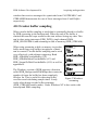
4.8 Circular buffer sampling .............................................................. 41
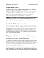
4.9 Streaming to disk.......................................................................... 42
4.9.1 How the Windows streamer works ................................. 42
4.10 Software triggering (Windows 3.1x/95 only) ............................ 43
4.10.1 Setting channel trigger details....................................... 44
4.10.2 Trigger notification ....................................................... 44
4.10.3 Setting the global trigger type (mode) .......................... 45
4.10.4 Performance................................................................... 48
4.10.5 Quick reference ............................................................. 48
4.11 Using XMS memory (DOS) and memory blocks
(Windows) .......................................................................................... 48
4.12 Aborting sampling with a keypress (DOS only)........................ 49
4.13 Using parallel boards to access more than 16 channels............. 49
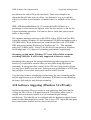
4.14 Using PC81A expansion boards to address more than 16
channels .............................................................................................. 50
5. Measuring temperatures..........................................................53
5.1 Reading thermocouple and CJC voltages .................................... 53
5.2 Converting a CJC voltage into the ambient temperature............. 53
5.3 Converting a TC voltage into a temperature................................ 54
5.4 Converting a RTD voltage into a temperature ............................. 54
5.5 Using a non-TC board to measure temperatures.......................... 54
6. Generating voltages and waveforms.......................................55
6.1 D/A Channel numbers .................................................................. 55
6.2 Generating voltages on D/A channels.......................................... 55
6.2.1 Parallel update ................................................................. 55
6.2.2 Converting microvolt values to binary ........................... 55
6.3 Generating waveforms on D/A channels ..................................... 56
6.3.1 Setting the transfer mode................................................. 56
6.3.2 Choosing channels for the waveforms ............................ 56
6.3.3 Data format ...................................................................... 56
6.3.4 Waveform frequency ....................................................... 57
6.3.5 Generating the waveform ................................................ 57
6.3.6 Background waveform generation .................................. 57
7. Configuration functions ...........................................................58
7.1 EDR_AllocBoardHandle.............................................................. 58
7.2 EDR_CanBeDetected ................................................................... 59
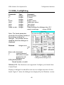
7.3 EDR_ConfigDialog ...................................................................... 60
7.4 EDR_DetectBoard........................................................................ 61
7.5 EDR_FreeBoardHandle................................................................ 62
7.6 EDR_GetADInGain ..................................................................... 63
7.7 EDR_GetADInRange ................................................................... 63
7.8 EDR_GetADInRangeMinMax..................................................... 64
7.9 EDR_GetADInType ..................................................................... 64
7.10 EDR_GetBase............................................................................. 65
7.11 EDR_GetBoardType .................................................................. 65
7.12 EDR_GetDAOutFixedRef.......................................................... 66
7.13 EDR_GetDAOutGain................................................................. 66
7.14 EDR_GetDAOutMode ............................................................... 67
7.15 EDR_GetDAOutRange .............................................................. 67
7.16 EDR_GetDAOutRangeMinMax ................................................ 68
7.17 EDR_GetDAOutTriggerSource ................................................. 68
7.18 EDR_GetDMALevels ................................................................ 69
7.19 EDR_GetIRQLevel .................................................................... 69
7.20 EDR_GetSysVersion.................................................................. 70
7.21 EDR_GetVxDVersion................................................................ 70
7.22 EDR_HasADGainJumper........................................................... 71
7.23 EDR_InitBoard........................................................................... 71
7.24 EDR_InitBoardType................................................................... 72
7.25 EDR_IsBaseAddressInUse......................................................... 73
7.26 EDR_LoadConfiguration ........................................................... 74
7.27 EDR_LoadConfigIni .................................................................. 74
7.28 EDR_ResetBoardNumber .......................................................... 75
7.29 EDR_RestoreDefaults ................................................................ 75
7.30 EDR_SaveConfiguration............................................................ 76
7.31 EDR_SaveConfigIni................................................................... 77
7.32 EDR_SetADInConfig................................................................. 77
7.33 EDR_SetADInGain .................................................................... 78
7.34 EDR_SetADInRange.................................................................. 79
7.35 EDR_SetADInType.................................................................... 79
7.36 EDR_SetBoardType ................................................................... 80
7.37 EDR_SetDAOutConfig .............................................................. 81
7.38 EDR_SetDAOutFixedRef .......................................................... 82
7.39 EDR_SetDAOutGain ................................................................. 82
7.40 EDR_SetDAOutMode................................................................ 83
7.41 EDR_SetDAOutRange ............................................................... 83
7.42 EDR_SetDAOutTriggerSource.................................................. 84
7.43 EDR_SetDMALevels ................................................................. 84
7.44 EDR_SetIRQLevel ..................................................................... 85
7.45 EDR_Version ............................................................................. 85
7.46 EDR_Version32 ......................................................................... 85
8. String functions.........................................................................87
8.1 EDR_ParseChanGainList............................................................. 88
8.2 EDR_StrADType.......................................................................... 89
8.3 EDR_StrBoardType ..................................................................... 89
8.4 EDR_StrDATriggerSource .......................................................... 89
8.5 EDR_StrDAUpdateMode............................................................. 90
8.6 EDR_StrError ............................................................................... 90
8.7 EDR_StrRange ............................................................................. 90
8.8 EDR_StrTCType .......................................................................... 90
8.9 EDR_StrTransferMode ................................................................ 90
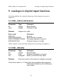
9. Analogue to digital input functions ........................................91
9.1 EDR_AddToADChanList ............................................................ 91
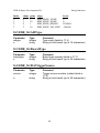
9.2 EDR_ADInBin ............................................................................. 91
9.3 EDR_ADInBinBackground ......................................................... 92
9.4 EDR_ADInBinCircularBuffer ..................................................... 93
9.5 EDR_ADInBinMem..................................................................... 94
9.6 EDR_ADInBinMemBackground ................................................. 95
9.7 EDR_ADInBinMemCircularBuffer ............................................. 96
9.8 EDR_ADInBinOneSample........................................................... 98
9.9 EDR_ADInBinToVoltage ............................................................ 98
9.10 EDR_ADInBinToVoltageBlock ................................................ 99
9.11 EDR_ADInOneVoltage............................................................ 100
9.12 EDR_ADInStreamBufStatus.................................................... 100
9.13 EDR_ADInVoltageToBin ........................................................ 101
9.14 EDR_AlignBuffer..................................................................... 101
9.15 EDR_BackgroundADInStatus ................................................. 102
9.16 EDR_BackgroundADInType ................................................... 103
9.17 EDR_BackgroundADInWraps................................................. 103
9.18 EDR_CalcCJCmC .................................................................... 104
9.19 EDR_CalcRTDmC ................................................................... 104
9.20 EDR_CalcTCmC ...................................................................... 105
9.21 EDR_ClearADTrigger.............................................................. 105
9.22 EDR_GetADBurstLen.............................................................. 106
9.23 EDR_GetADCClockTrigger .................................................... 106
9.24 EDR_GetADChanListIndex..................................................... 106
9.25 EDR_GetADChanListLen........................................................ 107
9.26 EDR_GetADChanTrigger ........................................................ 107
9.27 EDR_GetADChanTriggerType................................................ 108
9.28 EDR_GetADTransferMode...................................................... 108
9.29 EDR_GetADDisableAllInts ..................................................... 109
9.30 EDR_GetADKeyAbort............................................................. 109
9.31 EDR_GetADNoDelay .............................................................. 109
9.32 EDR_GetADTrigger................................................................. 110
9.33 EDR_GetADTriggerType ........................................................ 111
9.34 EDR_GetADUseTCInts ........................................................... 111
9.35 EDR_GetNotificationMsg........................................................ 112
9.36 EDR_GetNotificationWindow ................................................. 113
9.37 EDR_GetStreamBlockSize ...................................................... 113
9.38 EDR_GetStreamBuffer............................................................. 113
9.39 EDR_GetStreamFile................................................................. 114
9.40 EDR_PadFile ............................................................................ 114
9.41 EDR_SetADBurstLen .............................................................. 115
9.42 EDR_SetADCClockTrigger..................................................... 115
9.43 EDR_SetADChanListIndex ..................................................... 116
9.44 EDR_SetADChanListLen ........................................................ 116
9.45 EDR_SetADChanTriggerType ................................................ 117
9.46 EDR_SetADDisableAllInts...................................................... 117
9.47 EDR_SetADKeyAbort ............................................................. 118
9.48 EDR_SetADNoDelay............................................................... 118
9.49 EDR_SetADTransferMode ...................................................... 119
9.50 EDR_SetADTriggerType ......................................................... 120
9.51 EDR_SetADUseTCInts............................................................ 120
9.52 EDR_SetNotificationWindow.................................................. 121
9.53 EDR_SetStreamBlockSize ....................................................... 121
9.54 EDR_SetStreamBuffer ............................................................. 122
9.55 EDR_SetStreamFile ................................................................. 122
9.56 EDR_StopBackgroundADIn.................................................... 123
9.57 EDR_StreamToDisk................................................................. 123
9.58 EDR_StreamToDiskBackground ............................................. 124
9.59 EDR_StreamToDiskCircularBuffer ......................................... 125
9.60 EDR_UsesPCTimerInterrupts .................................................. 126
9.61 EDR_UVoltsToUAmps............................................................ 127
9.62 EDR_ValidADBurstLen .......................................................... 128
9.63 EDR_ValidADTransferMode .................................................. 128
10. Counter / Timer functions ...................................................129
10.1 EDR_CTClockSource .............................................................. 129
10.2 EDR_CTConfigure................................................................... 130
10.3 EDR_CTGateSource ................................................................ 131
10.4 EDR_CTRead........................................................................... 132
10.5 EDR_CTSoftGate..................................................................... 133
10.6 EDR_CTWrite .......................................................................... 133
10.7 EDR_Factorize ......................................................................... 134
10.8 EDR_GetADClockmilliHz....................................................... 134
10.9 EDR_GetCTClockSource ........................................................ 135
10.10 EDR_GetCTGateSource ........................................................ 135
10.11 EDR_GetCTInitialValue ........................................................ 136
10.12 EDR_GetCTInputFreqHz....................................................... 136
10.13 EDR_GetDAClockmilliHz..................................................... 136
10.14 EDR_CTLatchAll................................................................... 137
10.15 EDR_SetADClockmilliHz ..................................................... 137
10.16 EDR_SetCTInputFreqHz ....................................................... 138
10.17 EDR_SetDAClockmilliHz ..................................................... 139
11. Analogue output functions...................................................140
11.1 EDR_AddToDAChanList ........................................................ 140
11.2 EDR_BackgroundDAOutStatus............................................... 140
0.1. EDR_BackgroundDAOutType................................................. 141
11.4 EDR_DAOutBin....................................................................... 141
11.5 EDR_DAOutBinBackground................................................... 142
11.6 EDR_DAOutBinOneSample.................................................... 142
11.7 EDR_DAOutBinReadback....................................................... 143
11.8 EDR_DAOutBinToVoltage ..................................................... 143
11.9 EDR_DAOutUpdate................................................................. 144
11.10 EDR_DAOutVoltage.............................................................. 144
0.2. EDR_DAOutVoltageReadback ................................................ 145
11.12 EDR_DAOutVoltageToBin ................................................... 145
11.13 EDR_DAOutVoltageToBinBlock.......................................... 146
11.14 EDR_GetDAChanListIndex................................................... 146
11.15 EDR_GetDAChanListLen...................................................... 147
11.16 EDR_GetDADisableAllInts ................................................... 147
11.17 EDR_GetDAKeyAbort........................................................... 147
11.18 EDR_GetDATransferMode.................................................... 147
11.19 EDR_SetDAChanListIndex ................................................... 148
11.20 EDR_SetDAChanListLen ...................................................... 148
11.21 EDR_SetDADisableAllInts.................................................... 149
11.22 EDR_SetDAKeyAbort ........................................................... 149
11.23 EDR_SetDATransferMode .................................................... 150
11.24 EDR_StopBackgroundDAOut ............................................... 150
11.25 EDR_ValidDATransferMode ................................................ 151
12. Digital input/output functions .............................................152
12.1 EDR_DIOConfigurePort .......................................................... 152
12.2 EDR_DIOGetPortConfig ......................................................... 153
12.3 EDR_DIOLineInput ................................................................. 153
12.4 EDR_DIOLineOutput .............................................................. 154
12.5 EDR_DIOPortInput.................................................................. 154
12.6 EDR_DIOPortOutput ............................................................... 155
12.7 EDR_DIOPortInput16.............................................................. 155
12.8 EDR_DIOPortOutput16 ........................................................... 156
12.9 EDR_HasDOReadback ............................................................ 156
13. Memory functions (XMS) ....................................................157
13.1 EDR_AllocMem....................................................................... 157
13.2 EDR_CopyFromMem .............................................................. 158
13.3 EDR_CopyFromMemToMem.................................................. 158
13.4 EDR_CopyToMem................................................................... 159
13.5 EDR_DecimateIntArray ........................................................... 159
13.6 EDR_FreeMem......................................................................... 160
13.7 EDR_GetFreeMem................................................................... 160
13.8 EDR_GetMemBlockSize ......................................................... 160
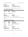
14. Validation functions .............................................................161
14.1 EDR_HasADInClock ............................................................... 161
14.2 EDR_HasBurstMode................................................................ 161
14.3 EDR_HasDAOutClock ............................................................ 161
14.4 EDR_HasDAOutIRQ ............................................................... 162
14.5 EDR_HasSHH .......................................................................... 162
14.6 EDR_GetDAOutNumBits ........................................................ 162
14.7 EDR_GetDAOutRefChannel ................................................... 163
14.8 EDR_NextADInGain ............................................................... 163
14.9 EDR_NextDAOutGain............................................................. 164
14.10 EDR_Num16BitDAOutputs................................................... 164
14.11 EDR_NumADInputs .............................................................. 164
14.12 EDR_NumCounters................................................................ 165
14.13 EDR_NumDAOutputs............................................................ 165
14.14 EDR_NumDIOPorts............................................................... 165
14.15 EDR_MaxADInThroughputHz.............................................. 166
14.16 EDR_MaxDAOutThroughputHz ........................................... 166
14.17 EDR_ValidADCClockTrigger ............................................... 166
14.18 EDR_ValidADInGain ............................................................ 167
14.19 EDR_ValidADInRange.......................................................... 167
14.20 EDR_ValidADInType............................................................ 167
14.21 EDR_ValidBoardType ........................................................... 167
14.22 EDR_ValidClockSource ........................................................ 168
14.23 EDR_ValidDAOutChan......................................................... 168
14.24 EDR_ValidDAOutFixedRef .................................................. 168
14.25 EDR_ValidDAOutGain.......................................................... 169
14.26 EDR_ValidDAOutMode ........................................................ 169
14.27 EDR_ValidDAOutRange ....................................................... 169
14.28 EDR_ValidDAOutTriggerSource .......................................... 170
14.29 EDR_ValidDMALevels ......................................................... 170
14.30 EDR_ValidDIOPortConfig .................................................... 170
14.31 EDR_ValidGateSource .......................................................... 171
14.32 EDR_ValidInterruptID........................................................... 171
14.33 EDR_ValidInterruptSource.................................................... 171
14.34 EDR_ValidIRQLevel ............................................................. 172
15. Default functions...................................................................173
15.1 EDR_DefaultADInGain ........................................................... 173
15.2 EDR_DefaultADInRange......................................................... 173
15.3 EDR_DefaultADInType........................................................... 173
0.3. EDR_DefaultDAOutFixedRef.................................................. 174
15.5 EDR_DefaultDAOutRange ...................................................... 174
15.6 EDR_DefaultDAOutTriggerSource ......................................... 174
15.7 EDR_DefaultDMALevels ........................................................ 174
15.8 EDR_DefaultIRQLevel ............................................................ 175
15.9 EDR_GetCJCChannelNumber................................................. 175
15.10 EDR_NumIOLocations .......................................................... 175
16. Interrupt functions ...............................................................176
0.4. EDR_EnableInterrupt ............................................................... 178
16.2 EDR_GetInterruptSource ......................................................... 178
16.3 EDR_InstallBoardISR .............................................................. 179
16.4 EDR_InstallISR........................................................................ 179
16.5 EDR_MaskBoardIRQ .............................................................. 180
16.6 EDR_MaskIRQ ........................................................................ 180
16.7 EDR_ResetInterrupt ................................................................. 181
16.8 EDR_SetInterruptSource.......................................................... 181
16.9 EDR_SetIntteruptMode............................................................ 182
16.10 EDR_UninstallBoardISR ....................................................... 182
16.11 EDR_UninstallISR ................................................................. 182
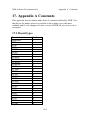
17. Appendix A Constants .........................................................184
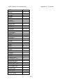
17.1 Board types ............................................................................... 184
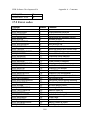
17.2 Error codes................................................................................ 186
17.3 Voltage ranges .......................................................................... 187
17.4 A/D input types......................................................................... 188
17.5 Transfer modes ......................................................................... 188
17.6 Burst settings ............................................................................ 188
17.7 ADC clock/trigger settings....................................................... 188
17.8 D/A update modes .................................................................... 188
17.9 D/A update trigger sources....................................................... 189
17.10 Counter/timer clock sources................................................... 189
17.11 Counter/timer gate sources..................................................... 189
17.12 Counter/timer gating .............................................................. 189
17.13 Counter/timer modes .............................................................. 189
17.14 Counter/timer numbers........................................................... 190
17.15 DIO port modes ...................................................................... 190
17.16 DIO port settings .................................................................... 190
17.17 Interrupt ID's........................................................................... 191
17.18 Interrupt enable and disable values........................................ 191
17.19 IRQ mask values..................................................................... 191
17.20 Notification codes .................................................................. 191
17.21 Thermocouple types ............................................................... 191
17.22 VxD flags................................................................................ 192
17.23 Trigger edge settings .............................................................. 192
17.24 Trigger mode settings............................................................. 192
18. Appendix B - Fine tuning EDRVXD.386 ...........................193
18.1 Single channel DMA ................................................................ 193
18.2 Dual channel DMA................................................................... 194
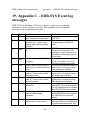
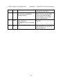
19. Appendix C – EDR.SYS Event log messages.....................196
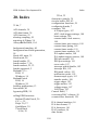
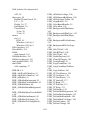
20. Index ......................................................................................198
EDR Software Development Kit
Introduction
1. Introduction
This manual is for the EDR software package. EDR is a powerful
application programming interface (API) between your data acquisition and
control application and Eagle Technologies line of plug in boards for PC's.
Your application can be written in any of several popular languages and can
run under DOS, Windows 3.1 (386 enhanced mode), Windows for
Workgroups 3.11 (386 enhanced mode), Windows 95 (16 and 32 bit) and
Windows NT 4.0. Source code for numerous demonstration programs is
provided for DOS and Windows in several different languages. The API
insulates you from the actual hardware details of the board(s) in use. This
makes it easier to write applications and to change boards as new models
are released.
EDR are supplied free with all supported boards and is available for
download on our web site. (http://www.eagle.co.za)
1.1 About EDR version 2.35
This release includes support for our new range of PC104-30FG boards.
These boards are based on our popular PC30FG boards. They are also
exactly compatible with them.
1.2 Feature EDR releases
The current EDR SDK will only support our ISA range boards and not our
newer PCI PnP range. The new EDR release will be known as EDR
Enhanced and can be used in conjunction with the current release. Please
note that EDR Enhanced will support the more popular ISA boards but is
mainly intended for the PCI boards. EDR Enhanced will have the same
functionality as EDR but will be easier to program and more powerful. It
will also only support the Windows 32 bit platform.
1.3 Boards supported
EDR currently supports the following boards (listed according to the
board’s primary function):
1
EDR Software Development Kit
Introduction
• The PC26*, PC30*, PC30B/C/D/DS/DS4/PGL/PGH, PC126* and
•
•
•
•
•
•
•
•
•
•
•
•
PC127* analogue to digital input boards.
The PC30FA, PC30FAS16, PC30FAS4, PC30F, PC30FS16, PC30FS4,
PC30GA, PC30GAS16, PC30GAS4, PC30G, PC30GS16 and PC30GS4
advanced analogue to digital input boards.
The PC30L†, PC30LA† and PC30LB† advanced 16 bit analogue to
digital input boards.
The PC166, PC166B, PC167, PC167A, PC167B and PC266 advanced
digital to analogue output boards.
The PC66, PC66A and PC66C digital to analogue output boards.
The PC63 and PC63C reed relay boards.
The PC73A and PC73C thermocouple and RTD boards.
The PC36, PC36B, PC36C, PC192 and PC192A digital IO boards.
The PC14, PC14A and PC14B digital IO and counter/timer boards.
The PC60 mV input and PC61 mA input boards.
The PC62B*, PC62C and PC65* optically isolated digital IO boards.
The PC104-72A Digital I/O Board
The PC104_30FG range of Analog Boards
* Not yet supported under Windows NT
† Only supported under Windows NT
As new boards are developed support will be added to the driver. Note that
some boards with different names (such as the PC36 / PC36B and the PC14
/ PC14A) are identical from a software perspective. These boards are given
the same ID number in the driver (PC36 and PC14 respectively).
The PC73A is unreliable in some fast computers (486+). It has been
replaced by the PC73C (8 TC or RTD inputs, 8 digital outputs and 8 digital
inputs).
1.4 Features
The major features of EDR include:
l
Extensive A/D, D/A, DIO and configuration functions are provided.
2
EDR Software Development Kit
l
l
l
l
l
l
l
l
l
l
l
l
l
l
Introduction
Polled, interrupt, single channel DMA and dual channel DMA data
acquisition fully supported at full throughput.
Software triggering (level + edge) on multiple A/D input channels
(Windows 3.1x and Windows 95 only).
Speed critical routines (such as polled sampling and waveform
generation) have been coded in assembler for maximum speed.
Streaming to disk and memory using only one DMA channel. This
allows unlimited amounts of data to be collected from all boards with
DMA.
Circular buffer sampling has now been extended to work with interrupt
sampling and streaming to memory and disk. This allows huge ring
buffers to be created in memory or on disk.
Interrupts are handled in a VxD under Windows 3.1x and Windows 95.
This minimises Windows interrupt latencies.
Interrupt and DMA sampling can be done completely in the background.
Status functions provide a "samples done" count for background
sampling operations. If 1000 samples have been acquired out of a block
of 200000 then these samples can be processed while the rest of the data
is acquired.
Parallel boards are fully supported allowing 32 or 48 channel systems to
be created.
Scaling functions convert binary values into voltages and visa versa.
IRQ functions make it easy to write and install interrupt handlers from C
and Pascal under DOS and Windows (16 bit only).
Thermocouple linearization functions are provided.
Driver functions provide extensive error reporting (45 different error
codes) and parameter checking making it easier to debug programs.
The DOS and Windows (16 and 32 bit) versions of EDR provide the
same API. You only need to learn one set of functions for DOS,
Windows and Windows NT.
1.5 EDR Driver structure
There are 3 main versions of EDR for DOS, Windows 3.1/95 and Windows
NT respectively.
3
EDR Software Development Kit
Introduction
1.5.1 DOS
The DOS versions of EDR consist of libraries of compiled code that are
linked into your executable at build time. The same library of functions is
provided in 3 different forms for C/C++, Borland/Turbo Pascal and Quick
Basic 4.5 respectively.
1.5.2 Windows 3.1 and Windows 95
The Windows 3.1x and Windows 95 version of EDR is split into three parts:
a 16 bit dynamic link library (EDR.DLL), a 32 bit DLL (EDR32.DLL) and a
VxD or virtual device driver (EDRVXD.386).
The VxD does interrupt and DMA data acquisition and the 16 bit DLL
handles all other functions. The 32 bit DLL is only used from 32 bit
applications running under Windows 95. It translates calls (thunks) down to
EDR.DLL to do most of its work. There is no real loss of speed due to this
thunking process as all the speed critical code is in the 32 bit VxD and not
the 16 bit DLL. Large parts of Windows 95 itself are implemented in
exactly the same way.
The distinction between EDR.DLL and EDRVXD.386 is usually invisible to
your applications as they call EDR.DLL (or EDR32.DLL) which in turn
calls the VxD if necessary. However some extra functions have been added
to optimise high speed DMA data acquisition using the VxD. The DLL’s
and VxD are in the C:\EDR\DLL directory.
1.5.3 Windows NT
The Windows NT version of EDR is split into two parts: a 32 bit dynamic
link library (EDR32.DLL) and a kernel mode device driver (EDR.SYS).
All direct access to hardware is done by EDR.SYS. The DLL checks
parameters and calls EDR.SYS to perform operations that require direct
hardware access. This is very different to the Windows 3.1x and Windows
95 DLL’s which access the hardware themselves.
4
EDR Software Development Kit
Introduction
Windows NT requires this scheme. It is slower than the direct access of
Windows 3.1x and Windows 95 but helps to maintain system integrity as
only trusted device drivers can access hardware.
Applications always call EDR32.DLL and never EDR.SYS.
1.6 Installation
To install the EDR SDK insert Disk 1 in drive A and run the windows
setup program. This will install the EDR SDK on your PC.
The paragraphs below contain operating system dependent installation
instructions.
1.6.1 Windows NT 4.0
Log on as Administrator (or another account with admin clearance) and run
SETUP.BAT found in the \EDR\WINNT directory. This will install the
kernel mode device driver (EDR.SYS) and EDR32.DLL. Setup will also
create the necessary registry keys and settings for you. After setup is done
you have to reboot your PC for the changes to take affect.
Setup runs a program called REGINI.EXE to create the registry entries for
EDR.SYS. You can use this when installing EDR.SYS on target systems for
your own applications. Just run REGINI with EDR.INI (found in
\EDR\WINNT).
When setup has completed go to Control Panel and choose "Eagle Board
Setup". Configure your boards and reboot. You need to know the exact
model number, base address and jumper settings for each board.
See 1.6.3 for more information on the Windows 95 and Windows NT
control panel applet and configuring boards.
The kernel mode device driver (EDR.SYS) reports errors (boards not found
etc.) to the system event log. Use the event viewer (in Start | Programs |
Admin tools) to view these. Appendix lists all possible event log errors with
explanations. If no boards have been configured or no boards can be found
5
EDR Software Development Kit
Introduction
EDR.SYS will not load and NT will display a "some services failed to start"
dialog box on boot.
Advanced users: You can avoid rebooting your PC when making further
changes to your board setup. You need to stop EDR.SYS (if it started),
change your configuration and restart it.
To stop EDR.SYS from the command line do:
To start EDR.SYS do:
net stop edr
net start edr
This only works if your PC has been rebooted at least once since
SETUP.EXE has completed successfully. NT caches registry entries
concerned with device drivers forcing the need to reboot.
1.6.2 Windows 3.1x, Windows 95 and DOS
The setup batch file in the EDR\WIN95 directory will install the win95
drivers by default. See instructions below for Windows 3.11 In this manual
C:\EDR will be used to refer to this directory. If you installed to drive D:
then take all references to C:\EDR to mean D:\EDR.
1.6.2.1 Windows 3.1 or 3.11
Run WIN31.EXE (found in your C:\EDR\WIN95 directory). This will mark
EDR.DLL as a Windows 3.1 executable. Copy EDR.DLL and
EDRVXD.386 from the C:\EDR\WIN95 directory to your
WINDOWS\SYSTEM directory.
Add the following line to SYSTEM.INI (found in your WINDOWS
directory) in the [386Enh] section:
device=edrvxd.386
If you are not using interrupt or DMA data acquisition functions then you
can omit this line. If you call a function that requires EDRVXD.386 the
function will return an appropriate error code. You will need to restart your
computer for this change to take effect.
6
EDR Software Development Kit
Introduction
1.6.2.2 Windows 95
Run WIN95.EXE (found in your C:\EDR\WIN95 directory). This will mark
EDR.DLL as a Windows 4.0 executable. If you do not do this 16 bit
applications will work but 32 bit apps will not load. Then copy EDR.DLL,
EDR32.DLL, EAGLE.CPL and EDRVXD.386 to your
WINDOWS\SYSTEM directory.
Add the following line to SYSTEM.INI (found in your WINDOWS
directory) in the [386Enh] section:
device=edrvxd.386
If you are not using interrupt or DMA data acquisition functions then you
can omit this line. If you call a function that requires EDRVXD.386 the
function will return an appropriate error code. You will need to restart your
computer for this change to take effect. Once you have restarted your
computer refer to 1.6.3 for information on how to configure your board(s).
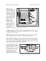
1.6.3 Windows 95 and NT Control Panel applet
Going to Control Panel and selecting “Eagle Board Setup” runs the Control
panel applet. This applet allows you to configure each of the boards in your
computer. If you add or remove boards, change jumper settings or want to
change software selectable settings use this utility.
1.6.3.1 Windows 95 specific information
Remember that this utility only configures boards for use with 32 bit
applications. The settings for each board are stored in the Windows 95
registry and the boards are initialised when EDR32.DLL is first loaded by a
32 bit application. The boards are not initialised when EDR.DLL is loaded
by a 16 bit application. This allows 16 bit applications to run and initialise
boards configured for 32 bit applications so long as no 32 bit applications
have loaded EDR32.DLL.
If a 16 bit application is running and has initialised a board configured in
Control Panel then that board cannot be accessed from 32 bit applications
loaded after the 16 bit application.
7
EDR Software Development Kit
Introduction
If a 32 bit application is running then no 16 bit application loaded after it
can initialise the same board. However 16 bit applications loaded after the
32 bit application can access the board using its board number instead of
allocating and initialising a board handle.
1.7 DOS languages supported
Each of the DOS languages has its own version of the EDR library and a
header or interface file. The header file tells the compiler what functions are
in the library and the calling syntax for each function. The library provides
the actual code that is placed in you application at link time. Each DOS
language has its own directory that contains its library, header file and demo
programs. The following DOS languages are supported:
• Borland C/C++ 3.x or 4.x (C:\EDR\EXAMPLES\C\DOS directory)
• Microsoft C/C++ 6.0 or 7.0 (C:\EDR\EXAMPLES\C\DOS directory)
• Borland Pascal/Turbo Pascal version 6.0 or 7.0
(C:\EDR\EXAMPLES\C\DOS directory)
Newer versions of these languages may also work but have not been tested.
Other languages (especially C compilers) may be able to use a version of the
driver meant for a different language.
1.8 Windows languages supported
The Windows languages all use the same version of the EDR library, only
the header files differ. They call functions in EDR.DLL (16 bit applications
under Windows 3.1x and Windows 95) or EDR32.DLL (two different
versions: one for Windows 95 and one for Windows NT).
Demo programs for each of the languages are in separate directories off the
Examples directory. The header files for Windows 3.1x, Windows 95 and
Windows NT are in the INCLUDE directory. As the API is the same as for
the DOS version of EDR the DOS demos may also be useful.
The following languages are supported:
• Microsoft C/C++ 6.0 or 7.0 (C:\EDR\EXAMPLES\C\WIN16 directory)
8
EDR Software Development Kit
Introduction
• Microsoft Visual C++ 4.0 (C:\EDR\EXAMPLES\C\WIN32 directory)
• Borland C/C++ 3.x or 4.x (C:\EDR\EXAMPLES\C\WIN16 directory
•
•
•
and C:\EDR\EXAMPLES\C\WIN32 directory)
Borland Pascal/Turbo Pascal version 6.0 or 7.0
(C:\EDR\EXAMPLES\TPAS directory)
Delphi version 1.0 and 2.0 (C:\EDR\EXAMPLES\DELPHI directory)
Microsoft Visual Basic 3.0 and 4.0 (C:\EDR\EXAMPLES\VB directory)
The 32 bit demos (in \EDR\EXAMPLES\C\WIN32) run under Windows 95
and Windows NT.
EDR can be used from any language that can call DLL functions just by
creating an appropriate header file.
1.9 Compiled demo programs
Some of the demo programs have compiled and are ready to run. If your
application is simple you may be able to use one of the following demos as
is:
1.9.1 Windows 95 and Windows NT (32 bit)
• \EDR\EXAMPLES\C\WIN32\NOTDEM32.EXE - GUI app - Samples
waveforms from selected A/D channels (in the background if possible)
and saves the data in a text file. This is a port of the 16 bit NOTDEMO.
• There are a number of console mode ports of the DOS demos. Have a
look in \EDR EXAMPLES\C\WIN32 and check the .c files for details on
what each demo does.
• There are two Visual Basic 4.0 demos in \EDR\EXAMPLES\VB.
LOGGER32 and WAVEIN32 are ports of the 16 bit applications listed
below. You need the Visual Basic 4.0 runtime DLL’s to run these demos.
The required files are in \EDR\EXAMPLES\VB. You need to copy
VB40032.DLL and GRAPH32.OCX to your \WINDOWS\SYSTEM
directory.
• \EDR\EXAMPLES\DELPHI\STREAM32\STREAMER.EXE. This is a
port of the 16 bit streamer application.
9
EDR Software Development Kit
Introduction
1.9.2 Windows 95 (16 bit) and Windows 3.1x
• C:\EDR\EXAMPLES\DELPHI\SCOPE\SCOPE.EXE -Powerful
•
•
•
•
•
•
•
oscilloscope application. Demonstrates the power of the new triggering
functions.
C:\EDR\ EXAMPLES\DELPHI\STREAMER\STREAMER.EXE Streams data from A/D channels to a disk file.
C:\EDR\ EXAMPLES \DELPHI\TEMPLOG\TEMPLOG.EXE - Logs
temperatures from TC’s and RTD’s to disk and displays them on screen.
C:\EDR\ EXAMPLES\C\WIN16\NOTDEMO.EXE - Samples waveforms
from selected A/D channels (in the background if possible) and saves the
data in a text file.
C:\EDR\ EXAMPLES\VB\LOGGER\LOGGER.EXE - Simple voltmeter
type application. Measures and displays the voltage on selected A/D
channels at specific intervals. If you do not have Visual Basic installed on
your system you will need to copy VBRUN300.DLL from the C:\EDR\
EXAMPLES \VB directory into your WINDOWS\SYSTEM directory.
C:\EDR\EXAMPLES\VB\WAVEIN\WAVEIN.EXE - Samples
waveforms from selected A/D channels (in background if possible) and
graphs the data using Visual Basic's graph control. If you do not have
Visual Basic installed on your system you will need to copy
VBRUN300.DLL, GSW.EXE and GRAPH.VBX from the C:\EDR\
EXAMPLES\VB directory into your WINDOWS\SYSTEM directory.
C:\EDR\EXAMPLES\VB\DIO\DIO.EXE - Allows all DIO ports to be
individually configured as input or output ports. Displays all ports and
allows values to be sent to output ports. If you do not have Visual Basic
installed on your system you will need to copy VBRUN300.DLL and
GRID.VBX from the C:\EDR\DLL\VB directory into your
WINDOWS\SYSTEM directory.
C:\EDR\ EXAMPLES\VB\LOGGER\TEMPMETR.EXE - Measures and
displays the temperature on selected A/D channels at specific intervals. If
you do not have Visual Basic installed on your system you will need to
copy VBRUN300.DLL from the C:\EDR\DLL\VB directory into your
WINDOWS\SYSTEM directory.
10
EDR Software Development Kit
Introduction
1.9.3 DOS
All of these demos accept the base address of the card to use as a command
line parameter. Generally they assume that the board is jumpered for the
factory default settings. They do display a configuration dialogue that
allows many of these settings to be changed if your board is jumpered
differently.
• C:\EDR\EXAMPLES\TPAS\ADINDEMO.EXE - Samples all A/D
•
•
•
•
•
•
•
•
•
•
•
channels at 10 KHz and dumps the data to a text file.
C:\EDR\EXAMPLES\TPAS\BITWALK.EXE - Walks a bit through all
digital output (or IO) ports on a board.
C:\EDR\EXAMPLES\TPAS\INIT.EXE - Detects what card is at the
specified base address.
C:\EDR\EXAMPLES\TPAS\STREAM.EXE - Streams data from all A/D
channels to disk (stream.dat) at 20 KHz.
C:\EDR\EXAMPLES\TPAS\VOLTGEN.EXE - Interactive program
allowing the voltage (and range and gain) on any D/A channel to be set.
C:\EDR\EXAMPLES\TPAS\VOLTMETR.EXE - Continuously displays
the voltage on each A/D channel.
C:\EDR\EXAMPLES\TPAS\WAVEGEN.EXE - Generates a saw tooth
waveform on a D/A channel.
C:\EDR\EXAMPLES\TPAS\WAVEGEN2.EXE - Generates a saw tooth
and square wave on two different D/A channels.
C:\EDR\EXAMPLES\TPAS\XMS.EXE - Samples waveforms into XMS
using streaming to memory or dual channel DMA. The first and last 512
samples are converted to text and dumped to a file.
C:\EDR\EXAMPLES\TPAS\TEMPMETR.EXE = Interactive program
that continuously displays the temperature on all input channels. The TC
type for each channel can be set.
C:\EDR\EXAMPLES\TPAS\RTDMETER.EXE = Interactive program
that continuously displays the temperature on all input channels. The
RTD type for each channel can be set.
C:\EDR\EXAMPLES\C\DOS\TCLOGGER.EXE = Batch program to log
TC temperatures from multiple boards to a comma delimited text file.
This is a complete application and not just a simple demo.
11
EDR Software Development Kit
Introduction
• C:\EDR\EXAMPLES\TPAS\DIOLOOP.EXE - Walks a bit through
digital output port 0 and reads all other digital input ports. Lines from
port 0 can be looped back to the other ports as a test.
• C:\EDR\EXAMPLES\TPAS\FREQCNT.EXE - Simple frequency counter
for the PC14B only. Measures the input frequency of channels 1 and 2 of
the counter/timer chip by using channel 0 to generate periodic interrupts.
Can be used to measure your PC's bus clock speed!
• C:\EDR\EXAMPLES\TPAS\EXTINT.EXE - Counts external interrupts
for boards with an external interrupt input.
1.10 How this manual is organised
• Chapter 2 has a section for each language that explains how to create an
•
•
•
•
•
•
•
•
•
•
•
•
•
•
application that uses EDR and gives a summary of the demos provided
for the language. You should read the section for your language before
looking at the other parts of this manual.
Chapter 3 gives general information on programming using the API. It is
important that you read and understand this chapter.
Chapter 4 describes how to use the A/D input functions.
Chapter 5 describes how to measure temperatures.
Chapter 6 describes how to use the D/A output functions.
Chapter 7 is a reference for functions for configuring and initialising
boards.
Chapter 8 is a reference for functions that convert numeric error codes,
board names and so on into strings.
Chapter 9 is a reference for functions for analogue to digital input.
Chapter 10 is a reference for counter / timer functions.
Chapter 11 is a reference for functions for do digital to analogue output.
Chapter 12 is a reference for functions for digital input and output.
Chapter 13 is a reference for functions for working with blocks of
memory (XMS for DOS).
Chapter 14 is a reference for validation functions.
Chapter 15 is a reference for default functions.
Chapter 16 is a reference for functions that install interrupt routines and
control interrupt generation.
12
EDR Software Development Kit
Introduction
• Appendix A lists all the constants used by EDR.
• Appendix B provides detailed information how to configure the VxD for
maximum performance under windows.
13
EDR Software Development Kit
Building applications using EDR
2. Building applications using EDR
This chapter explains how to build an application that uses EDR in all of the
supported languages.
2.1 DOS languages
When the application is compiled a header file is used to tell the compiler
what functions are in the driver and the parameters they expect. When the
application is linked code from EDR (in a library) is combined with your
code to form your executable file.
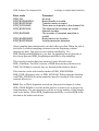
2.1.1 Borland C/C++
Follow these steps:
1. Make sure you are using the large memory model.
2. Include C:\EDR\INCLUDE\DOS\EDR.H in all files that call EDR
functions or use constants defined in EDR.H. You can do this by putting
the following line at the top of each file:
#include "c:\edr\inlcude\dos\edr.h"
3. Link your application with C:\EDR\LIB\DOS\EDR.LIB (if you are
using the IDE you can just add it to your project).
C++ users need not add extern "C" { } around EDR.H as this has been done
inside the file.
If you get any "Fixup overflow" errors when linking then one or more of
your files have been compiled for a different memory model. Rebuild all
files using the large memory model.
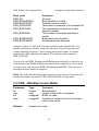
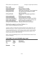
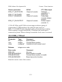
Project files have been provided for all of the demo programs. A makefile
(MAKEFILE.BC) is also provided to build all of the demos using Borland
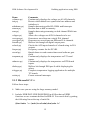
C/C++. The demos in the C:\EDR\EXAMPLES\C\DOS directory are as
follows:
14
EDR Software Development Kit
Demo
voltmetr.prj
init.prj
adindemo.prj
stream.prj
xms.prj
voltgen.prj
wavegen.prj
wavegen2.prj
bitwalk.prj
xcheck.prj
freqcnt.prj
ctread.prj
tempmetr.prj
rtdmeter.prj
dioloop.prj
tclogger.prj
extint.prj
Building applications using EDR
Comments
Continuously displays the voltage on all A/D channels.
Detects which board is at a particular base address and
initialises it.
Samples data using polled IO, DMA and Interrupts.
Streams data to disk or memory.
Samples data using streaming or dual channel DMA into
XMS.
Allows the voltages on all D/A channels to be set.
Generates a waveform on a single D/A channel.
Generates two waveforms on different D/A channels.
Walks a bit through all digital output ports.
Checks the A/D input channels of a board using its D/A
outputs.
Frequency counter for the PC14B.
Simple demo to read counter/timers and software gate
them.
Continuously displays the temperature on TC board
inputs.
Continuously displays the temperature on RTD board
inputs.
Walks a bit through DIO port 0 while displaying the
others.
Complete temperature logging application for multiple
TC boards.
Counts external interrupts.
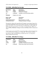
2.1.2 Microsoft C/C++
Follow these steps:
4. Make sure you are using the large memory model.
5. Include \EDR\INCLUDE\DOS\EDR.H in all files that call EDR
functions or use constants defined in EDR.H. You can do this by putting
the following line at the top of each file:
#include "c:\edr\include\dos\edr.h"
15
EDR Software Development Kit
Building applications using EDR
6. Link your application with C:\EDR\LIB\DOS\EDR.LIB (if you are
using the Programmers Workbench you can just add it to your program
list).
C++ users need not add extern "C" { } around EDR.H as this has been done
inside the file.
If you get any "Fixup overflow" errors when linking then one or more of
your files have been compiled for a different memory model. Rebuild all
files using the large memory model.
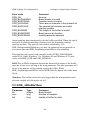
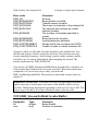
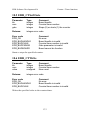
Program list files (PWB makefiles) have been provided for all of the demo
programs. A makefile (MAKEFILE.MSC) is also provided to build all of
the demos using Microsoft C/C++. The demos in the
C:\EDR\EXAMPLES\C\DOS directory are as follows:
Demo
voltmetr.mak
init.mak
adindemo.mak
stream.mak
xms.mak
voltgen.mak
wavegen.mak
wavegen2.mak
bitwalk.mak
xcheck.mak
freqcnt.mak
ctread.mak
tempmetr.mak
rtdmeter.mak
Comments
Continuously displays the voltage on all A/D channels.
Detects which board is at a particular base address and
initialises it.
Samples data using polled IO, DMA and Interrupts.
Streams data to disk or memory.
Samples data using streaming or dual channel DMA into
XMS.
Allows the voltages on all D/A channels to be set.
Generates a waveform on a single D/A channel.
Generates two waveforms on different D/A channels.
Walks a bit through all digital output ports.
Checks the A/D input channels of a board using its D/A
outputs.
Frequency counter for the PC14B.
Simple demo to read counter/timers and software gate
them.
Continuously displays the temperature on TC board
inputs.
Continuously displays the temperature on RTD board
inputs.
16
EDR Software Development Kit
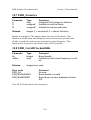
dioloop.mak
tclogger.mak
extint.mak
Building applications using EDR
Walks a bit through DIO port 0 while displaying the
others.
Complete temperature logging application for multiple
TC boards.
Counts external interrupts.
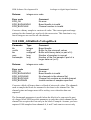
2.1.3 Borland / Turbo Pascal
Follow these steps:
7. Copy EDR60.TPU or EDR70.TPU from C:\EDR\LIB to your units
directory as EDR.TPU. EDR60 for version 6.0 and EDR70 is for version
7.0.
8. Add EDR to the uses clause of each program or unit in your application
that uses EDR procedures, functions or constants (e.g. uses DOS,
EDR; )
If you get a "unit file format" error when compiling you application then
you are using the wrong version of EDR. Contact us if you get this error
when using a version of Turbo/Borland Pascal newer than 7.0. Note that
Turbo Pascal version 5.5 or earlier is not supported.
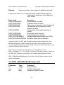
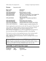
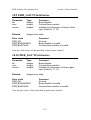
The demos in the C:\EDR\EXAMPLES\TPAS directory are as follows:
Demo
voltmetr.pas
init.pas
adindemo.pas
stream.pas
xms.pas
voltgen.pas
wavegen.pas
wavegen2.pas
bitwalk.pas
xcheck.pas
Comments
Continuously displays the voltage on all A/D channels.
Detects which board is at a particular base address and
initialises it.
Samples data using polled IO, DMA and Interrupts.
Streams data to disk or memory.
Samples data using streaming or dual channel DMA into
XMS.
Allows the voltages on all D/A channels to be set.
Generates a waveform on a single D/A channel.
Generates two waveforms on different D/A channels.
Walks a bit through all digital output ports.
Checks the A/D input channels of a board using its D/A
outputs.
17
EDR Software Development Kit
freqcnt.pas
ctread.pas
tempmetr.pas
rtdmeter.pas
dioloop.pas
extint.pas
Building applications using EDR
Frequency counter for the PC14B.
Simple demo to read counter/timers and software gate
them.
Continuously displays the temperature on TC board
inputs.
Continuously displays the temperature on RTD board
inputs.
Walks a bit through DIO port 0 while displaying the
others.
Counts external interrupts.
2.2 Windows languages (16 and 32 bit)
When the application is compiled a header file is used to tell the compiler
what functions are in the driver and the parameters they expect. When the
application is linked the linker inserts references to functions in EDR.DLL
(or EDR32.DLL for 32 bit apps) into your code - the actual code is not
added.
These references are only resolved to call EDR.DLL or EDR32.DLL at load
or run time, hence the term dynamic link library. Thus while your
applications .EXE file will be smaller, you need to distribute EDR.DLL and
EDRVXD.386 (Windows 3.1x and Windows 95) or EDR32.DLL and
EDR.SYS (Windows NT) with your application and install them on target
systems. 32 bit Windows 95 apps also need the Windows 95 version of
EDR32.DLL.
2.2.1 Borland & Microsoft C/C++ (16 and 32 bit)
Follow these steps:
1. Include C:\EDR\INCLUDE\EDR.H in all files that call EDR functions
or use constants defined in EDR.H. You can do this by putting the
following line at the top of each file:
#include "c:\edr\include\edr.h"
16 bit:
18
EDR Software Development Kit
Building applications using EDR
2. Link your application with C:\EDR\LIB\EDR.LIB (if you are using the
Borland IDE or the Microsoft Programmers Workbench you can just
add it to your project or program list). This library does not contain any
code. It is just an import library that tells the linker that the functions in
it are in EDR.DLL.
32 bit:
2. Microsoft Visual C++ users need to link with EDR32.LIB (this is a
COFF format library). Borland C/C++ users need to link with
EDR32OMF.LIB (this is OMF format library). If you are using another
compiler you will probably need to use EDR32OMF.LIB. If you are
using an integrated development environment (IDE) you can just add
the appropriate library to your project.
C++ users need not add extern "C" { } around EDR.H as this has been done
inside the file.
Note that you can use any 16 bit memory model but the large memory
model is recommended. 32 bit apps can be built as GUI or CONSOLE.
One 16 bit demo (NOTDEMO.EXE in C:\EDR\EXAMPLES\C\WIN16) and
4 32 bit demo’s are provided (NOTDEM32.EXE et al in
C:\EDR\EXAMPLES\WIN32). NOTDEM32 is a port of the 16 bit
NOTDEMO application. This is a full Windows application. It can be used
to sample data and save as text for later import into a spreadsheet. It
demonstrates features unique to the Windows version of EDR such as
notification messages sent when background sampling operations complete.
The demo programs provided for the DOS version of the driver in the
C:\EDR\EXAMPLES\C\DOS directory can be built as 16 bit EASYWIN
apps and 32 bit CONSOLE apps and will work with small modifications.
They are also simpler and shorter than a full Windows application written in
C and make better demos.
To build one of these as an EASYWIN application just load the project file
for the demo into Borland's Windows IDE or Microsoft's PWB and run it as
a Windows application.
19
EDR Software Development Kit
Building applications using EDR
Two of the DOS demos (STREAM and ADINDEMO) have been built as
32 bit CONSOLE mode apps with very few changes. They are in
\EDR\EXAMPLES\WIN16.
2.2.2 Borland / Turbo Pascal and Delphi
Follow these steps:
1. Copy EDR.TPW or EDR.DCU or EDR32.DCU from C:\EDR\LIB to
your units directory. EDR.TPW is for Borland Pascal 7.0, EDR.DCU is
for Delphi 1.0 and EDR32.DCU is for Delphi 2.0. These units are just
import units that tell the compiler that the functions are in EDR.DLL or
EDR32.DLL.
2. Add EDR or EDR32 (for Delphi 2.0) to the uses clause of each program
or unit in your application that uses EDR procedures/functions or
constants (e.g. uses wincrt, EDR; ).
If you get a "unit file format" error when compiling you application then
you are using the wrong version of EDR. Contact us if you get this error
when using a version of Turbo/Borland Pascal newer than 7.0 or Delphi
newer than 3.0.
The DOS demos in the C:\EDR\EXAMPLES\TPAS directory can be
recompiled as Windows applications by adding wincrt to the uses clause
of each one and rebuilding them using the Windows compiler.
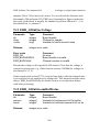
2.2.3 Visual Basic (16 and 32 bit)
If you are using VB (16 bit) you just have to add
\EDR\INCLUDE\EDR.BAS to your project. If you are using VB (32 bit)
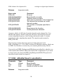
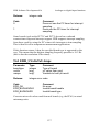
just add EDR32.BAS to your project. The following demos each in
directories off C:\EDR\EXAMPLES\VB show how to use EDR from Visual
Basic.
Demo
wavein
wavein32
Comments
16 bit: Acquires and graphs waveforms from A/D channels.
32 bit: Port of 16 bit wavein
20
EDR Software Development Kit
logger
logger32
dio
tempmetr
Building applications using EDR
16 bit: Simple voltmeter type application.
32 bit: Port of 16 bit logger
16 bit: Input values from and output values to DIO ports
16 bit: Simple temperature meter type application
21
EDR Software Development Kit
Programming guidelines
3. Programming guidelines
This chapter gives the basic information you will need to know to
successfully program using EDR. You should read this chapter before
reading the rest of the manual.
3.1 Board handles and board numbers
All EDR functions that program boards or work with configuration
information require a board handle or board number as their first
parameter. The board handle or board number defines which board is
affected by the function call. This scheme has several advantages:
l
l
l
l
There is no need for a "select board" function.
Working with parallel boards is much easier.
The Windows API itself uses handles for many of its own objects.
Different applications using EDR at the same time cannot interfere with
each other (Windows).
3.1.1 Board handles
Board handles are integers obtained by calling EDR_AllocBoardHandle
(see 7.1). 32 bit applications running under Windows 95 should use board
numbers instead (see 3.1.2). Applications running under Windows NT
have to use board numbers. For compatibility reasons
EDR_AllocBoardHandle always returns 1 under Windows NT.
Windows NT: Ignore the rest of this section. Read 3.1.2 on board numbers
instead.
Once allocated a board handle must be initialised to a particular board
before the board can be accessed. This is done by calling EDR_InitBoard
(7.23) or EDR_InitBoardType (7.24) with the base address or
EDR_LoadConfiguration (7.26). These functions link the board handle to
the board and fill in configuration information for it. The board handle can
now be used to access the board using EDR functions.
22
EDR Software Development Kit
Programming guidelines
EDR_InitBoard attempts to detect what board is present at the base
address specified. It is not possible to do this with simple digital IO boards
(such as the PC36) without changing the state of the outputs. This is not
safe as the board may be controlling external equipment!
EDR_InitBoardType takes an extra parameter specifying the type of board
installed and does not make any attempt to check if it is present or not. In
addition EDR_LoadConfiguration does not attempt to check the board type
if the board was originally initialised using EDR_InitBoardType.
All board handles allocated must be released using EDR_FreeBoardHandle
(7.57) before the application terminates. If a board handle is not freed then it
is lost and any board initialised to it cannot be accessed using EDR. The
current version EDR supports up to 8 board handles.
When a board handle is initialised using EDR_InitBoard or
EDR_InitBoardType the driver assumes that the board detected at the base
address is jumpered for the factory default settings. If any of the jumpers
have been changed then the configuration functions in chapter 7 must be
used to inform EDR of the correct settings.
3.1.2 Board numbers
Board numbers refer to boards configured via our control panel applet (see
1.6.3). They are normally only available to 32 bit applications running under
Windows 95 and Windows NT. A board number can be used in place of a
board handle when calling EDR functions.
When accessing a board via a board number there is no need to initialise the
board using EDR_InitBoard. The board is initialised and configured with
information stored in the system registry when EDR32.DLL is first loaded
(Windows 95) or when EDR.SYS is loaded (Windows NT). Applications
can restore the board to its registry defined state by calling
EDR_ResetBoardNumber (see x).
3.1.2.1 Windows 95
If a 16 bit application is running and has initialised a board configured in
Control Panel then that board cannot be accessed from 32 bit applications
loaded after the 16 bit application.
23
EDR Software Development Kit
Programming guidelines
If a 32 bit application is running then no 16 bit application loaded after it
can initialise the same board. However 16 bit applications loaded after the
32 bit application can access the board using its board number instead of
allocating and initialising a board handle.
3.2 Software register copies
Many boards have some registers that are write only. EDR keeps a copy of
the last value written to these registers using an EDR function for use in
future calls that may need this value. This means that if you sometimes
bypass EDR and program the board directly problems may occur when you
do use EDR functions.
Example: When configuring the direction of a port on an 8255 it is
necessary to set the direction and mode of all 3 ports on the chip
simultaneously. EDR allows the direction of all programmable DIO ports to
be set independently of each other. To do this it needs to know the last
configuration byte that was written to the chip. EDR has no way of knowing
this if you program the chip directly and then use an EDR function to
change something later.
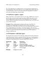
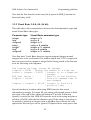
3.3 Parameters and data types
The function descriptions in the following chapters all list their parameters
in the same format. Generic names are used for the type of each parameter
rather than having a separate table for each language. Here is a parameter
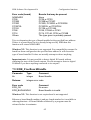
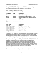
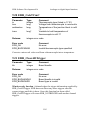
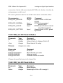
listing for a hypothetical driver function called EDR_Function:
Parameter
i16
sparam
uarray
i16ptr
i32
Type
integer
string
unsigned*
integer*
long
Comment
16 bit integer
Character string
Array of unsigned integers
Variable to hold a 16 bit integer
32 bit integer
Returns:
integer error code
24
EDR Software Development Kit
Programming guidelines
Each of the following sections will show how to call this function from a
different language and any special techniques required. Note that the header
files provided for each language are also useful references for the
parameters required for each function and the calling syntax.
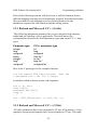
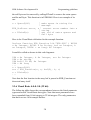
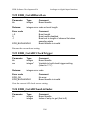
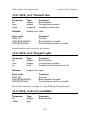
3.3.1 Borland and Microsoft C/C++ (16 bit)
The following information assumes that you are using the large memory
model and are building a 16 bit application. This table shows the
correspondence between the listed parameter types and actual C/C++ data
types:
Parameter type
integer
long
unsigned
string
integer*
long*
unsigned*
C/C++ parameter type
int
long
unsigned
char far *
int far *
long far *
unsigned far *
Here is the C prototype for the example function:
int far pascal EDR_Function(int, char far
*,unsigned far *,int far *,long);
It could be called as shown in this code fragment:
int a, b, err;
char s[80];
unsigned buf[100];
long c;
...
err = EDR_Function(a, s, buf, &b, c);
...
3.3.2 Borland and Microsoft C/C++ (32 bit)
All value parameters have been expanded to 32 bits. All pointers to 16 bit
quantities except actual samples have been expanded to 32 bits. This table
25
EDR Software Development Kit
Programming guidelines
shows the correspondence between the listed parameter types and actual
C/C++ data types:
Parameter type
integer
long
unsigned
string
integer*
long*
unsigned*
C/C++ parameter type
int
int
unsigned
char *
int *
int *
unsigned *
Pointers to sample buffers are left in 16 bit form. This means that an
integer* becomes a short* and an unsigned* becomes an
unsigned short*.
Here is the C prototype for the example function:
int far pascal EDR_Function(int, char*, unsigned
short*, int*, long);
It could be called as shown in this code fragment:
int a, b, err;
char s[80];
unsigned short buf[100];
int c;
...
err = EDR_Function(a, s, buf, &b, c);
...
3.3.3 Borland/Turbo Pascal and Delphi 1.0 (16 bit)
This table shows the correspondence between the listed parameter types and
actual pascal data types:
26
EDR Software Development Kit
Parameter type
integer
long
unsigned
string
integer*
long*
unsigned*
Programming guidelines
Borland/Turbo Pascal parameter type
integer
longint
word
string
var integer
var longint
var word
Here is the pascal function prototype for the example function:
function EDR_Function( p1:integer; p2:string; var
p3:word; var p4:integer; p5:longint) :integer;
It could be called as shown in this code fragment:
var
var
var
var
...
err
...
a, b, err :integer;
s :string;
buf :array[0..99] of word;
c :longint;
:= EDR_Function(a, s, buf[0], b, c);
Note that the first location in the array buf is passed to EDR_Function not
the actual array itself.
3.3.4 Delphi 2.0 & 3.0 (32 bit)
All value parameters have been expanded to 32 bits. All pointers to 16 bit
quantities except actual samples have been expanded to 32 bits. This table
shows the correspondence between the listed parameter types and actual
Delphi 2.0 data types:
27
EDR Software Development Kit
Parameter type
integer
long
unsigned
string
integer*
long*
unsigned*
Programming guidelines
Delphi 2.0 parameter type
integer
integer
cardinal
PChar
var integer
var integer
var cardinal
Pointers to sample buffers are left in 16 bit form. This means that an
unsigned* becomes a var word.
Special care has to be taken when using EDR functions that return
information in strings. You need to use a long string variable
(AnsiString) to hold the result. By default variables declared as
string are long strings ($H compiler option). You also need to call
SetLength to make sure the string has enough space to hold the result.
For EDR functions a length of 80 is fine. Example:
var s :string;
// use AnsiString if using $HSetLength(s,80); // space for result
EDR_StrBoardType(PC30F,PChar(s));
// now s = ‘PC30F’ with a chr(0) appended to it
Here is the pascal function prototype for the example function:
function EDR_Function( p1:integer; p2:PChar; var
p3:word; var p4:integer; p5:integer) :integer;
It could be called as shown in this code fragment:
var a, b, err, c :integer;
var s :string;
var buf :array[0..99] of word;
...
SetLength(s,80);
err := EDR_Function(a, PChar(s), buf[0], b, c);
...
28
EDR Software Development Kit
Programming guidelines
Note that the first location in the array buf is passed to EDR_Function not
the actual array itself.
3.3.5 Visual Basic 3.0 & 4.0 (16 bit)
This table shows the correspondence between the listed parameter types and
actual Visual Basic data types:
Parameter type
integer
long
unsigned
string
integer*
long*
unsigned*
Visual Basic parameter type
integer or %
long or &
integer or %
string or $ variable
integer or % variable
long or & variable
integer or % variable
Note that since Visual Basic does not support unsigned integers normal
integers have to be used instead. If a number higher that 32767 is required it
has to be converted to a negative integer before being passed to the function
as in the following code fragment:
Dim longvar As Long, intvar As Integer
longvar = 40000 ' Assign the number to a long var
intvar = longvar - 65536 ' Convert it to a negative
' integer
EDR_Sub( intvar )
' Pass it to the function
longvar = intvar
' This bit assumes that it
' was changed
longvar = longvar + 65536 ' Convert it back to a
' positive long
Special care has to be taken when using EDR functions that return
information in strings. You must fill your string with enough spaces to hold
the result of the call before calling the function. The built in function
Space$() is useful for this. EDR will store the result in the string and place a
null byte (Chr$(0)) after the last character used. If the string is just going to
be printed or passed to a function such as MsgBox this is fine as the extra
spaces after this null byte will be ignored. If required these extra spaces and
29
EDR Software Development Kit
Programming guidelines
the null byte can be removed by calling RTrimZ to remove the extra spaces
and the null byte. This function is in EDR.BAS. Here is an example of its
use:
s = Space$(80)
' make space in string for
' message
EDR_StrError error, s ' convert error number into a
' string
s = RTrimZ(s)
' get rid of extra spaces and
' null byte
Here is the Visual Basic definition for the example function:
Declare Function EDR_Function Lib "EDR.DLL" ( BYVAL
a As Integer, BYVAL s As String, buf as Integer, b
as Integer, BYVAL c as Long) As Integer
It could be called as shown in this code fragment:
DIM
DIM
DIM
DIM
...
s =
err
s =
...
a As Integer, b As Integer, err As Integer
s As string
buf(0 TO 99) As Integer
c As Long
Space$(80)
= EDR_Function(a, s, buf(0), b, c)
RTrimZ(s)
Note that the first location in the array buf is passed to EDR_Function not
the actual array itself.
3.3.6 Visual Basic 4.0 & 5.0 (32 bit)
The following table shows the correspondence between the listed parameter
types and actual Visual Basic data types. Note that most parameters have
been expanded from 16 bit integers to 32 bit integers. The only parameters
that have not are 16 bit sample buffers.
30
EDR Software Development Kit
Parameter type
integer
long
unsigned
string
integer*
long*
unsigned*
Programming guidelines
Visual Basic parameter type
long or &
long or &
long or &
string or $ variable
long or & variable
long or & variable
long or & variable
Special care has to be taken when using EDR functions that return
information in strings. You must fill your string with enough spaces to hold
the result of the call before calling the function. The built in function
Space$() is useful for this. EDR will store the result in the string and place a
null byte (Chr$(0)) after the last character used. If the string is just going to
be printed or passed to a function such as MsgBox this is fine as the extra
spaces after this null byte will be ignored. If required these extra spaces and
the null byte can be removed by calling RTrimZ. This function is in
EDR.BAS. Here is an example of its use:
s = Space$(80)
' make space in string for
' message
EDR_StrError error, s ' convert error number into a
' string
s = RTrimZ(s)
' get rid of extra spaces and
' null byte
Here is the Visual Basic definition for the example function:
Declare Function EDR_Function Lib "EDR32.DLL" (
BYVAL a As Long, BYVAL s As String, buf as Integer,
b as Long, BYVAL c as Long) As Long
It could be called as shown in this code fragment:
DIM
DIM
DIM
DIM
...
s =
a As Long, b As Long, err As Long
s As string
buf(0 TO 99) As Integer ‘ 100 16 bit samples
c As Long
Space$(80)
31
EDR Software Development Kit
Programming guidelines
err = EDR_Function(a, s, buf(0),b, c)
s = RTrimZ(s)
...
Note that the first location in the array buf is passed to EDR_Function not
the actual array itself.
32
EDR Software Development Kit
Acquiring analogue data
4. Acquiring analogue data
The EDR API provides several different ways to collect A/D data. This
chapter reviews the issues, problems and functions involved with each
method. Which method you choose will depend on your board(s) and
application. The A/D functions are described in detail in chapter 9.
4.1 A/D data format
When raw data is read from a board it is stored in the binary format used by
that board. This format varies depending on the board in use and you should
consult your board manual for details. The exception is data from the PC126
and PC127 which is converted from two’s complement to offset binary by
EDR before being stored in memory.
The binary data is usually scaled to voltages before processing. EDR
provides 2 scaling functions to convert from binary to voltages.
EDR_ADInBinToVoltage (9.9) converts single binary values into voltages.
EDR_ADInBinToVoltageBlock (9.10) converts blocks of binary values
from multiple channels into voltages. These scaling functions use the
configuration information for the board (input ranges, gains etc.) to do the
conversion so it is important that these settings are correct.
These functions actually return microvolt values instead of floating point
data (e.g. 1.5 V is returned as 1500000 µV). This avoids the problems
associated with the different floating point formats used by various
languages. Also integer values are faster to work with than floating point
values.
4.2 Simple A/D
EDR provides two simple functions that get the voltage on a single A/D
input channel. EDR_ADInOneVoltage (9.11) reads the data and converts it
to a voltage while EDR_ADInBinOneSample (9.8) returns the binary data.
Use these functions when exact timing is not important or when very slow
sampling is required.
33
EDR Software Development Kit
Acquiring analogue data
4.3 Sampling blocks of A/D data
The block sampling functions samples blocks of accurately timed A/D data
using the timing hardware on the board. EDR supports 5 different ways of
transferring data from the card to memory: polled IO, interrupts, single
channel DMA, dual channel DMA and streaming. All of the transfer modes
except polled IO can be used for background sampling.
Data is stored in the same order as the channels are
sampled. Figure 14 shows how data would be placed in
an array if channels 4, 7 and 8 were sampled.
Channel
(sample)
4 (0)
7 (0)
8 (0)
4 (1)
7 (1)
8 (1)
...
Positio
n in
array
0
1
2
3
4
5
...
There are two main block sampling functions:
EDR_ADInBin (9.2) and EDR_ADInBinBackground
(9.3). A number of other functions are used to select the
transfer mode, sampling frequency and so on and to
monitor the status of background transfers. Streaming
Figure 1.
to disk and sampling into XMS (or Windows global
memory blocks) are started by different functions. These functions are
discussed in the sections below.
4.4 Selecting the transfer mode
EDR_SetADTransferMode (9.49) selects the transfer mode to use for future
block A/D on the board. EDR_GetADTransferMode (9.28) returns the
current transfer mode. The transfer mode constants are listed in 17.5.
Each transfer mode is discussed below:
4.4.1 Polled IO (EDR_POLLED)
With polled IO EDR continually monitors the board waiting for conversions
to complete. When each conversion has completed the data is read by the
processor and stored in memory. This process requires the full attention of
the processor and cannot be done in the background.
To avoid missing samples while interrupts are processed all interrupts
should be disabled if the A/D frequency is greater than 1000 Hz. This will
shut down the keyboard, mouse, real time clock and any serial port activity
34
EDR Software Development Kit
Acquiring analogue data
for the duration of the sampling operation. The EDR_SetADDisableAllInts
(9.46) function can be used to control this behaviour. The Windows version
of EDR ignores this function hence this transfer mode should not be used
from Windows applications if any of the other modes are available.
A maximum of 32000 samples can be captured in one block using this mode
for DOS and Windows.
Windows NT: Polled sampling for a block of data is not supported under
Windows NT.
4.4.2 Interrupts (EDR_INTR)
Interrupt sampling is excellent for low speed applications (<10 KHz) as it
works very well in the background allowing the PC to get on with other
work. The board generates an interrupt when each conversion completes.
The processor suspends the currently executing program and calls an
interrupt service routine which reads the data from the board and stores it in
memory. The program that was running is resumed on exit from the service
routine.
A maximum of 32000 samples can be captured in one block using this mode
for DOS and Windows. There is no limit for Windows NT.
EDR will emulate interrupt sampling using the PC’s counter/timer interrupts
for some boards that do not have interrupt hardware. The PC73 and PC73C
are supported in this manner. See EDR_UsesPCTimerInterrupts (9.60) for
more information.
DOS: The data buffer must be in conventional memory. On fast machines
higher transfer rates may be possible (> 30 KHz).
Windows: On fast machines fairly high sample rates can be achieved. The
Windows version of EDR has been tested at up to 17 KHz on a 33 MHz 486
using a PC30D. The interrupts are handled in the VxD minimising latency
time and allowing the high speed to be maintained. However if a DOS box
is opened while interrupt sampling is taking place some data may be
lost. Windows shuts down all interrupts for about 1 ms while opening a
DOS box.
35
EDR Software Development Kit
Acquiring analogue data
4.4.3 Single channel DMA (EDR_SINGLEDMA)
Single channel DMA is a very efficient way to sample data. It requires very
little work on the part of the processor and supports the maximum transfer
rate of the board (even on slow machines). The PC's DMA controller is
programmed to transfer data from the card to memory without going
through the processor. The transfer can proceed in the background. If you
need to transfer less than 32000 samples and your board has DMA use
this mode as you first choice for DOS and Windows.
DOS: The data buffer must have space for at least twice as many samples as
are required. This is necessary to deal with limitations imposed by the DMA
controller hardware. DMA transfers cannot cross physical page boundaries.
These boundaries occur every 64K or 128K depending on the DMA level. If
a page boundary lies within the buffer the transfer has to start at the
boundary. Once the transfer has completed the data is copied down to the
start of the buffer. This copying process is handled transparently by EDR.
Note that the buffer can be in XMS memory.
Windows: The data buffer need only be big enough for the number of
samples required. EDR uses internal buffers for the transfer if it crosses a
page boundary or is not physically contiguous. The data is copied out of the
internal buffer as needed. This process is described in more detail in
appendix B.
Windows NT: Single channel DMA and streaming are handled in exactly
the same way. There is essentially no difference between them.
A maximum of 32000 samples can be captured in one block using this mode
for DOS and Windows. There is no limit under Windows NT.
4.4.4 Dual channel DMA (EDR_DUALDMA)
Dual channel DMA uses 2 DMA channels to transfer data continuously
from the card to memory. As each channel finishes a block of data, the
board automatically starts transferring using the other channel. The first
channel can now be reprogrammed to transfer the next block. Thus dual
36
EDR Software Development Kit
Acquiring analogue data
channel DMA can be used to capture as many samples as will fit into
memory at full board throughput.
Windows NT: Dual channel DMA is not supported. Streaming is more
reliable.
DOS: The buffer needs only to have enough space for the data, it does not
have to be bigger as for single channel DMA. The buffer can also be in
XMS memory allowing megabytes of data to be collected in one block. This
mode can be used for background sampling.
Windows: This mode can be used very efficiently under Windows but
streaming is more reliable. The 2 channels can be used to cope with noncontiguous areas of the buffer. This means that dual channel transfers are
not normally buffered and are therefore more efficient. However dual
channel DMA does require the processor to reprogram the DMA controller
between blocks. If you need to sample at throughputs of more that 40 KHz
you should read appendix B and configure EDRVXD.386 and your board
accordingly.
4.4.5 Streaming (EDR_STREAM)
Streaming uses a single DMA channel programmed for circular buffer
mode. In circular buffer mode the buffer is continuously filled with data
looping back to the start of the buffer when the end is reached. As data is
transferred into the buffer from the board it is copied to somewhere else in
memory or to a disk file. Unlimited amounts of data can be captured using
this method even from boards without dual channel DMA. If you are using
Windows and need to capture more than 32000 samples in a block you
should use this mode even if you only want to transfer to memory - it is
more reliable than dual channel DMA.
Software triggering on A/D input channels only works with
EDR_STREAM.
Windows NT uses this streaming mechanism for both single channel DMA
and interrupt sampling. Software triggering is not currently supported under
Windows NT. When it is it will work with single DMA, streaming and
interrupts.
37
EDR Software Development Kit
Acquiring analogue data
The remainder of this section discusses issues common to streaming to
memory and disk. Section 4.9 deals with disk streaming in particular.
The streamer writes data out to disk or memory in fixed size blocks. You
can set the size of these blocks using EDR_SetStreamBlockSize (9.53). If
you are doing high speed streaming to disk under DOS you should use a
block size equal to the cluster size of the destination disk.
The streamer always waits until a full block of data has been collected
before writing it out. If you are doing slow streaming you may want to use a
small block size. This will reduce the number of extra samples that are taken
at the end to fill up the last block. These extra samples are discarded but still
take time to collect. An alternative way to avoid this effect is to collect a
total number of samples that is a multiple of the block size.
DOS: You must give the streamer a second buffer to use for streaming to
memory or disk. This buffer is used to hold the data before it gets copied to
disk or the destination buffer. EDR_SetStreamBuffer (9.54) must be used to
set this buffer (which cannot be in XMS).
Windows: Read section 4.9 for more important information on disk
streaming.
4.5 Selecting channels to sample
EDR maintains a channel list for the board. This list can hold up to 32
channels to sample. In general the channels can be in any order and can be
repeated (when using the PC127 the channels must be in ascending order
and cannot be repeated). EDR_SetADChanListLen (9.44) and
EDR_AddToADChanList (9.1) are used to put channels into the channel
list.
38
EDR Software Development Kit
Acquiring analogue data
4.6 Setting the sampling frequency
The A/D conversion or sample frequency can be set using
EDR_SetADClockmilliHz (10.15). Normally one channel is converted on
each strobe, however some boards support
burst/block mode or simultaneous sample
and hold.
4.6.1 Burst/block mode and
simultaneous sample and hold
When sampling in burst mode each strobe
triggers a series of conversions done at
the maximum speed of the board. This is
useful when the skew between sampled
channels must be minimised.
Simultaneous sample and hold also only
takes place in burst/block mode on boards
that support it. EDR_SetADBurstLen
(9.41) can be used to enable and disable
burst/block mode.
Figure 2. Burst/block mode
and SSH
Figure 2 shows the spacing between samples taken from channels 0,1,2 and
3 on a PC30D at 25 KHz in normal and burst mode. The latter part of the
diagram shows how the samples would be spaced if taken on a PC30DS
which uses simultaneous sampling and hold in burst mode. The PC30D has
a maximum throughput of 200 KHz.
4.7 Background sampling
Background sampling can be done using any transfer mode except polled.
EDR_ADInBinBackground (9.3) is used to start sampling.
EDR_BackgroundADInStatus (9.15) can be used to check how many
samples have been acquired so far. These samples will be in the buffer or
file and can be processed or graphed while the rest of the data is acquired.
When all (or enough) of the data has been acquired
EDR_StopBackgroundADIn (9.56) must be called to stop sampling. This
39
EDR Software Development Kit
Acquiring analogue data
function makes sure that all acquisition is stopped and releases DMA/IRQ
levels and buffers.
DOS: When the transfer mode is set to EDR_DUALDMA or
EDR_STREAM then EDR_BackgroundADInStatus must be called
periodically so that the DMA controller can be reprogrammed or data
copied out of the stream buffer. When doing dual channel DMA at 200 KHz
the status function must be called at least every 150 ms or sampling will
stop. How often the status function needs to be called when doing streaming
depends on the size of the stream buffer. Using a 16384 sample buffer at
200 KHz allows up to about 80 ms between calls. Slower speeds and bigger
buffers allow proportionately more time. For high speed disk streaming it is
best to call the function as often as possible.
Windows: The status function does not need to be called at any particular
rate or even called at all (if notification messages are used). The VxD takes
care of this task if configured correctly (see appendix B). Note that other
programs may cause background streaming and dual channel DMA to fail if
they are ill behaved and do not release the CPU for long periods of time.
EDRVXD.386 has been written so as to minimise this possibility but it is
best to test your application with other programs it may run with to make
sure that this does not happen.
Windows NT: The status function does not need to be called at any
particular rate or even called at all.
4.7.1 Windows notification messages
EDR can send messages to your application when background sampling
operations complete and when channels trigger. Unfortunately this feature
cannot be used from languages (such as Visual Basic) that do not let you
process messages directly.
Windows NT: Notification messages are not yet supported.
These messages are sent to a window in your application.
EDR_GetNotificationMsg (9.35) gets the ID number used for all EDR
messages. See the description of this function for details on how the
messages are formatted. EDR_SetNotificationWindow (9.36) sets the
40
EDR Software Development Kit
Acquiring analogue data
window that receives messages for a particular board. NOTDEMO.C and
STREAMER demonstrate the use of these messages from C and Delphi
respectively.
4.8 Circular buffer sampling
When circular buffer sampling is used data is continually placed in a buffer
by EDR (operating in the background). When the end of the buffer is
reached the transfer loops around to the start without losing any data. This
can be done using interrupts (EDR_INTR), single channel DMA
(EDR_SINGLEDMA) and streaming to disk or memory (EDR_STREAM).
When using streaming to disk or memory in circular
buffer mode huge ring buffers (megabytes of data)
can be created. Circular buffer sampling can be used
very effectively with software triggering. Read
EDR_ADInBinCircularBuffer (9.4),
EDR_ADInBinMemCircularBuffer (9.7) and
EDR_StreamToDiskCircularBuffer (9.59) as well as
appendix B.
The Windows version of EDR supports a function
called EDR_BackgroundADInWraps that counts the
number of times the buffer has been completely
filled so far. This is useful for detecting buffer
Figure 3.Windows
overflows and calculating sample times. It only
streaming
works when doing circular buffer streaming
(EDR_STREAM transfer mode). Under Windows NT it also works with
interrupt and DMA sampling.
41
EDR Software Development Kit
Acquiring analogue data
4.9 Streaming to disk
Streaming to disk is done by setting the transfer mode to EDR_STREAM
and calling EDR_StreamToDiskBackground (9.58) or
EDR_StreamToDiskCircularBuffer (9.59). Once streaming has started you
can call EDR_BackgroundADInStatus to check on its progress. This
function will return an error if any buffers overflow. You must call
EDR_StopBackgroundADIn once streaming has completed.
Windows 95 32 bits only: You must call EDR_BackgroundADInStatus at
regular intervals to ensure data is written to disk and the buffers do not
overflow. When doing high speed streaming in interval of 10 ms is OK. The
easiest way to do this is to set up a Windows timer to do the calls.
4.9.1 How the Windows streamer works
Streaming to disk under Windows uses two buffers as shown in figure 3.
The first small buffer is filled by the DMA controller and emptied into the
second larger buffer by a routine in the VxD or kernel mode device driver.
Data is dumped from the second buffer to the disk file by the DLL. The
second buffer has to be big so that it does not overflow when Windows is
busy and no data can be dumped to disk. This also overcomes the problem
posed by lazy writing disk caches.
The size and memory for second buffer can be set using
EDR_SetStreamBuffer. If you do not specify a buffer the driver will allocate
a 256 KB buffer and free it when sampling is stopped. You will generally
need at least a 1024 KB buffer for high speed streaming.
The streamer writes data from the second buffer to disk in blocks. The size
of these blocks can be set using EDR_SetStreamBlockSize (9.53) and
should be a multiple of the cluster size of the destination disk for high speed
streaming. When doing circular buffer streaming to disk the size of the
buffer must be a multiple of the block size.
The streamer always waits until a full block of data has been collected
before writing it out. If you are doing slow speed streaming you may want
to use a small block size. This will reduce the number of extra samples that
42
EDR Software Development Kit
Acquiring analogue data
are taken at the end to fill up the last block. These extra samples are
discarded but still take time to collect. An alternative way to avoid this
effect is to collect a total number of samples that is a multiple of the block
size.
EDR_ADInStreamBufStatus (9.12) returns the buffer fullness as a
percentage. It also returns the highest value for this statistic so far for the
current streaming operation. You can use this to check that your second
buffer is big enough.
The streamer has been tested on a 486 DX50 with a VESA local bus IDE
controller running Windows 95 and maintained 200 KHz throughput with a
1024 KB buffer. It has been tested on a similar machine with a 100 MHz
DX4 processor running Windows for Workgroups 3.11. This machine
achieved 330 KHz easily. Using 32-bit file access (an option in Windows
for Workgroups 3.11) improves streaming performance significantly.
Streaming to disk under Windows NT is not fully reliable at speeds
exceeding 100 KHz. It will be fully supported in the next release.
Streaming takes place in the background allowing other programs to run.
However you should be careful what you run while doing high speed
streaming. If a program takes control of the CPU for a long period of time
you may get a buffer overrun error. Starting a new application or a DOS box
may produce a lot of disk activity and cause a buffer overrun.
You also need to have enough physical memory for your streaming buffer
and the applications you run while streaming. If Windows starts thrashing
the heavy disk activity may disrupt streaming.
4.10 Software triggering (Windows 3.1x/95 only)
Software triggering allows you start or stop capturing data based on the
voltage on one or more A/D input channels. This feature allows you to
sample data in a manner similar to a conventional digital storage
oscilloscope. This should not be confused with the hardware trigger feature
found on most data acquisition cards. This is just a TTL input line that gates
the counter/timer channel used to clock conversions.
43
EDR Software Development Kit
Acquiring analogue data
Software triggering only works with the Windows version of EDR and only
with the streaming transfer mode. Streaming requires a board with DMA or
REPSTRING to work. Using an A/D card and software triggering may be
slower than a digital storage scope but unlimited amounts of data can be
collected. EDR can even trigger on data being streamed to disk!
The oscilloscope demo program (in \EDR\EXAMPLES\DELPHI\SCOPE)
demonstrates software triggering using EDR. You can use this program to
experiment with different trigger modes and to find the best trigger settings
for your input signals.
4.10.1 Setting channel trigger details
You can specify a trigger level
(voltage) and edge for each channel
you are going to sample. This is done
by calling
EDR_SetADChanTriggerType (9.45)
for each channel with one of the
constants shown in Figure 4 and a level
value in microvolts.
Constant
EDR_EDGE_NONE
Value
0
EDR_EDGE_RISING
1
EDR_EDGE_FALLING
2
Explanation
Do not trigger
on channel
Trigger on
rising edge
Trigger on
falling edge
Figure 4. Channel trigger settings
The edge detection algorithm is simple and fast and can give incorrect
results on noisy signals. It is best to pick a voltage level that lies on a
rapidly rising or falling portion of the input signal. This reduces the
possibility of a noise spike giving an incorrect edge. Use the oscilloscope
program to examine your input and pick a good level and edge.
4.10.2 Trigger notification
Whenever a channel triggers EDR sends a message to the notification
window for the board (if any). See 4.7.1 for details on notification
messages. This is done regardless of the current trigger mode.
You can also find out if a channel has triggered by calling
EDR_GetADTrigger (9.32). This function returns the trigger sample and
channel number or an error code if no triggers have been detected so far.
EDR stops detecting triggers once one has been found until
EDR_ClearADTrigger (9.21) has been called.
44
EDR Software Development Kit
Acquiring analogue data
4.10.3 Setting the global trigger type (mode)
EDR supports 4 different trigger
modes. Call EDR_SetADTriggerType
(9.50) with one of the constants shown
in Figure 5 to select the mode you
require. Each mode is discussed in
detail in the following paragraphs.
No triggering (EDR_TRIG_NONE)
This is the default setting. All
individual channel trigger settings are
ignored and no triggering is done.
Constant
EDR_TRIG_NONE
Value
0
EDR_TRIG_PRE
1
EDR_TRIG_MID
2
EDR_TRIG_POST
3
EDR_TRIG_USER
4
Explanation
No triggering
(normal)
Trigger
precedes data
Trigger is in
middle of data
Trigger
follows data
Triggers are
reported but
are ignored
Figure 5. Trigger modes
Pre triggering (EDR_TRIG_PRE)
With pre triggering the trigger precedes the data (see
Figure 6). EDR only starts putting data in your buffer
once one of the sampled channels has triggered. This is
the simplest trigger mode. The following pseudo code
shows how to setup a pre triggering operation:
Figure 6. Pre
triggering
...Set the transfer mode to EDR_STREAM, set sampling
frequency, channels, gains etc. as normal...
EDR_SetADChanTriggerType(bh,0,EDR_EDGE_RISING,4000000)
EDR_SetADChanTriggerType(bh,2,EDR_EDGE_FALLING,2000000)
Trigger on a rising edge at 4000000 µv (4V) on channel 0 or a falling edge
at 2V on channel 2. This assumes that channels 0 and 2 are among those
being sampled.
EDR_SetADTriggerType(bh,EDR_TRIG_PRE,0)
Trigger precedes the data.
EDR_ADInBinBackground(bh,...)
Start background sampling ... data will only appear in the buffer after either
channel 0 or 2 has triggered.
Mid triggering (EDR_TRIG_MID)
45
EDR Software Development Kit
Acquiring analogue data
Mid triggering is more flexible than pre triggering. The
trigger can be anywhere in the waveform you want to
capture (see Figure 7). This mode should be used with
circular buffer streaming as EDR continuously transfers
data into your buffer while looking for a trigger. You
specify the number of samples that must be captured after
a channel has triggered. Once these have been captured
and stored in your buffer sampling stops and you have
data before and after the trigger.
Figure 7. Mid
triggering
You should set the size of your circular buffer to the number of samples you
want to capture in total. Remember that the buffer size must be a multiple of
the streamer block size or you will get an error from
EDR_ADInBinCircularBuffer. You can use EDR_SetStreamBlockSize
(9.53) to change this.
Use the postsamples parameter of EDR_SetADTriggerType to set the
number of samples to capture on and after the scan containing trigger. Note
that the scan containing the trigger is included in this count. The following
pseudocode example shows how to do this:
...Set the transfer mode to EDR_STREAM, set sampling frequency, gains
etc. as normal...
EDR_SetADChanListLen(bh,0)
EDR_AddToADChanList(bh,1)
EDR_AddToADChanList(bh,3)
Sample channels 1 and 3.
EDR_SetADChanTriggerType(bh,3,EDR_EDGE_FALLING,1000000)
Trigger on a falling edge at 1000000 µv (1V) on channel 3.
EDR_SetADTriggerType(bh,EDR_TRIG_MID,30000)
Capture 30000 samples after the start of the trigger scan.
EDR_SetStreamBlockSize(bh,1000)
Note that the buffer size (100000) is a multiple of the block size and also of
the number of channels being sampled.
EDR_ADInBinCircularBuffer(bh,100000,...)
Start circular buffer background sampling into a 100 000 sample circular
buffer. When sampling stops 30000 samples will be on and after the trigger
scan and 70000 before it.
46
EDR Software Development Kit
Acquiring analogue data
Normally it is easiest to use buffer sizes and postsample figures that are
multiples of the number of channels being sampled. This avoids any messy
half scans in the buffer.
You can call EDR_GetADTrigger (9.32) to find out if a channel has
triggered yet and the position of the trigger (if any) in the buffer. This
information can be used to decide when sampling has completed i.e. when
the required number of samples have been captured after the trigger. The
following pseudocode example shows this calculation:
if EDR_GetADTrigger(bh, trig, chan)=EDR_OK then
trig = trig-(trig mod EDR_GetADChanListLen(bh))
done = EDR_BackgroundADInStatus(bh)-trig
if done<0 then done=done+100000
else done=0
Note how the trigger sample position (trig) is adjusted to the start of the
scan containing the trigger. EDR captures postcount samples from this point
not from the trigger sample itself. Once the done value reaches your
postcount value you can call EDR_StopBackgroundADIn.
EDR_AlignBuffer (9.14) can be used to move all the data in the buffer
around so that the oldest sample is in the first position in the buffer. This
simplifies working with the data.
It is possible that a trigger will occur soon after sampling starts i.e. before
the buffer has been completely filled once. In this case you will get less data
before the trigger. You can call EDR_BackgroundADInWraps to find out
how many times the buffer has been filled to check for this.
Post triggering (EDR_TRIG_POST)
This mode is identical to mid triggering with a
postsamples value of 0. The trigger immediately follows
the data (see Figure 8). Note that this means that the scan
containing the trigger sample is not stored in the buffer.
User triggering (EDR_TRIG_USER)
47
Figure 8. Post
triggering
EDR Software Development Kit
Acquiring analogue data
When triggering in this mode EDR does not start or stop sampling when
channels trigger. It just looks for triggers and reports them using notification
messages. You can also check by calling EDR_GetADTrigger (9.32).
Remember that once a trigger has been detected EDR disables trigger
detection until you call EDR_ClearADTrigger (9.21). Triggers closely
following the first trigger may be missed.
4.10.4 Performance
Naturally sampling with trigger detection uses more CPU cycles than
normal streaming. This effect is not noticeable on today’s machines. A 133
MHz Pentium sampling at 200 KHz with trigger detection on all channels
only spends about 10% of CPU doing the acquisition.
4.10.5 Quick reference
Function
EDR_SetADTriggerType
EDR_GetADTriggerType
EDR_SetADChanTriggerType
EDR_GetADChanTriggerType
EDR_GetADTrigger
EDR_GetADChanTrigger
EDR_ClearADTrigger
Ref.
9.50
9.33
9.45
9.27
9.32
9.26
9.21
Description
Set global trigger mode
Get global trigger mode
Set channel trigger edge + level
Get channel trigger edge + level
Get trigger sample and channel
Get trigger sample for channel
Clear trigger info and look again
4.11 Using XMS memory (DOS) and memory blocks
(Windows)
EDR provides functions to access XMS memory from DOS and global
memory blocks from Windows. These functions behave in the same way to
provide compatibility.
EDR_ADInBinMem (9.5) and EDR_ADInBinMemBackground (9.6) are
equivalent to the normal ADInBin... functions except that they transfer data
into a memory block.
48
EDR Software Development Kit
Acquiring analogue data
4.12 Aborting sampling with a keypress (DOS only)
DOS programs can set a flag that allows users to abort non-background
sampling operations by pressing a key. The data collected up to the keypress
is left in the buffer and can be used normally. This feature is controlled by
EDR_SetADKeyAbort (see 9.47).
4.13 Using parallel boards to access more than 16
channels
EDR supports the use of multiple boards in parallel when using background
sampling. Each board must be jumpered for a different DMA level. For
example 3 PC30D’s (or PC30Dxx, PC30PGx, PC30Fxx and PC30Gxx)
could be used in parallel on DMA levels 5, 6 and 7 respectively. It is
possible to synchronise the boards by setting jumpers so one operates as the
master and the others as slaves all off the same A/D clock.
The master should
PC30Dxx and PGx PC30Fxx and PC30Gxx
Jumpers
EDR_SetADCClockTrigger
be jumpered so that
W18 W19 W20
parameter
the clock strobes for
in
in
out
EDR_ADC_MASTER
Master
the ADC converter
Out in out
EDR_ADC_SLAVE
Slave
are outputted on the
Figure 9. Master / slave configuration
external trigger line
on the connector (see figure 9). Each of the slaves should be jumpered for
external clocking (see figure 9) and the external trigger lines of all boards
connected together. The master board clocks the slave boards. The newer
PC30Fxx and PC30Gxx boards do not require any jumper changes as
EDR_SetADCClockTrigger (9.42) can be used to configure ADC strobes as
required.
All the normal sampling parameters for each board should then be set
normally with the exception of the sampling frequency. This only has to be
set on the master as all the slave boards will use this clock. Then start
sampling on the slave boards (using EDR_ADInBinBackground or one of
the other background sampling functions) and then on the master. The slave
boards will only begin converting when the master starts and stop when the
master stops. Each conversion strobe from the master will result in one
49
EDR Software Development Kit
Acquiring analogue data
channel being converted on each board. The FIFO’s on each board ensure
that any conflict for DMA cycles does not result in lost data.
When doing parallel board sampling under Windows it may be necessary to
increase the size of the VxD’s DMA buffer. Each 32000 sample single
DMA transfer and each streaming operation requires 64K of space. The
background sampling functions return error EDR_NOFREEDMABUF (-36)
if there is not enough free space in the buffer. Increasing the size of the
buffer is described in appendix B.
Also remember that the DMA controller has a theoretical maximum
transfer rate of about 900 000 samples/second in an AT class machine. If
the maximum throughput of your system is close to this you may lose data.
4.14 Using PC81A expansion boards to address
more than 16 channels
The PC81A is an input expander board for the PC30 series A/D boards. It
consists of a comparator and four 16 way muxes connected to 64 input
terminals. The comparator compares an 8 bit address against a PC81A board
number set on a dip switch. This allows multiple PC81A's to be connected
in parallel each addressing 64 channels.
The mux inputs for each PC81A and the comparator inputs are normally
connected to the digital lines of the A/D board in use. All the muxes share
common input lines so 4 of the 64 channels are available at a time. Jumpers
on the PC81A allow the 4 selected A/D signals to be mapped to channels 03, 4-7, 8-11 or 12-15 of the A/D board.
This allows 4 PC81A’s to be accessed at the same time using all 16 A/D
input channels. Each of the PC81A’s would have the same dip switch
setting and be jumpered for a different block of PC30 A/D inputs.
The PC81A includes a header containing all the cable signals. This allows
multiple boards to be stacked on top of each other so that only the bottom
board needs to be connected to the PC30 via a cable.
50
EDR Software Development Kit
Acquiring analogue data
EDR provides
functions to directly
access the channels
on up to 16 PC81A's
connected in parallel.
These functions only
work if the PC81A's
are wired to the A/D
board as shown in
figure 11 (the
standard cable
configuration). Of
course you can use
any connection
Figure 10. Standard PC81A connection scheme
scheme you wish and
use EDR DIO
functions to select PC81's and muxes yourself.
In addition the first 4 PC81A’s must have their dip switches set to 0. The
second 4 must be set to 1, the next 4 to 2 and the last 4 to 3. You may use
less than 16 PC81A boards.
EDR_FindPC81Channel returns the value to output to port 0 (A) and the
A/D board input to read to access a multiplexed input channel.
EDR_ADInPC81Voltage returns the voltage on a particular multiplexed
input (it calls the find function and outputs to port 0). You must configure
port 0 as output before calling EDR_ADInPC81Voltage. Figure 11 shows
the encoding used by EDR_FindPC81Channel.
The comparator on the PC81
compares the PC81 number
field to the number set on the
PC81's dip switches. Switch
1 on the PC81 is the least
significant. Switches 5, 6, 7
and 8 must all be off as
unconnected address inputs
Figure 11. Multiplexed channel encoding
51
EDR Software Development Kit
Acquiring analogue data
to the PC81A are pulled low.
For example: If you call EDR_ADInPC81Voltage with a channel number of
132 and your board is jumpered for single ended A/D inputs then the PC81
with (517/256)=2 set on its dip switches will be selected (switch 3 on, all
others off). The voltage could be read on channel 0 of the PC30.
52
EDR Software Development Kit
Measuring temperatures
5. Measuring temperatures
This chapter describes EDR support for thermocouple linearization, cold
junction compensation and RTD measurement. It is assumed that you have
some knowledge of these concepts. If not please refer to the hardware
manual for your board before reading this chapter.
5.1 Reading thermocouple and CJC voltages
The voltage on each thermocouple in a system is read using the normal
simple A/D input functions such as EDR_ADInOneVoltage (9.11). The
voltage from a cold junction compensation channel is read in the same
manner.
EDR also supports interrupt sampling from the PC73 and PC73C. This is
done using the PC’s timer tick interrupt. You need to call
EDR_SetADClockmilliHz (10.15) to set the frequency,
EDR_SetADTransferMode (9.49) with EDR_INTR to use interrupt
sampling and then EDR_ADInBinBackground (9.3) or
EDR_ADInBinCircularBuffer (9.4) to start sampling data. You may want to
use EDR_SetADBurstLen (9.41) as well to scan multiple channels on each
“strobe”.
EDR_GetCJCChannelNumber (15.9) returns the channel number of a
boards CJC input or -1 if the board has none. This is normally one more
than the number of the highest TC channel available on the board. For
example on the PC73A this function returns 8 as this board has 8 TC
channels numbered from 0 to 7. Use this function rather than hard coding 8
into your code. If we bring out a TC board with more or less channels then
you should be able to run your program unchanged using the new board.
5.2 Converting a CJC voltage into the ambient
temperature
EDR_CalcCJCmC (9.18) converts a microvolt value read from the board's
CJC channel into a value in milli °C. Milli °C values are used to avoid
having to use floating point numbers. To convert to °C just divide by 1000.
53
EDR Software Development Kit
Measuring temperatures
5.3 Converting a TC voltage into a temperature
EDR_CalcTCmC (9.20) converts a microvolt value read from a TC channel
into a temperature in milli °C compensating for the ambient temperature at
the junction block. It requires that you specify what type of thermocouple is
being used and the ambient temperature. EDR supports 8 different TC types
listed in 17.21.
5.4 Converting a RTD voltage into a temperature
EDR_CalcRTDmC (9.19) converts a microvolt value read from a RTD
channel into a temperature in milli °C. This function assumes that you are
using our RTD auxiliary board.
5.5 Using a non-TC board to measure temperatures
There is nothing to stop you from using a board with enough gain (such as a
PC30GA) to measure temperature. You can still use EDR_CalcTCmC to
convert the voltages from the thermocouples into temperatures. A channel
connected to a CJC chip is not necessary if you can control the temperature
of the junction block or have some other means of measuring it.
54
EDR Software Development Kit
Measuring temperatures
6. Generating voltages and waveforms
EDR provides functions to set the voltages on D/A channels and to generate
waveforms. Note that many boards do not support hardware clocked
waveform generation on their DAC's (e.g. PC30 series).
6.1 D/A Channel numbers
8 bit and 12 bit D/A channels (DACS) are numbered from 0. 16 bit channels
are numbered from 16 even if the board only has 16 bit channels (e.g.
PC266). For example the PC167B has 8 12 bit channels (numbered 0 to 7)
and one 16 bit channel (numbered 16).
6.2 Generating voltages on D/A channels
The easiest way to generate a voltage on a D/A channel is to call
EDR_DAOutVoltage (11.10). This function sets the voltage on a single
DAC.
6.2.1 Parallel update
If a D/A channel has been configured for preload (parallel) update mode
then the voltage set on the DAC will only be reflected on the output pin
when an update trigger is received. This feature is used to change the
voltage on several channels simultaneously. Update triggers can be
generated from software by calling EDR_DAOutUpdate (11.9). Note that
not all boards support preload mode.
6.2.2 Converting microvolt values to binary
The simple voltage output function, EDR_DAOutVoltage (11.10), converts
the microvolt value it is given to a binary value before outputting it. If you
need quick updates from within a loop use EDR_DAOutVoltageToBin
(11.12) to convert the microvolt value to binary outside of the loop. Then
call EDR_DAOutBinOneSample (11.6) to set the voltage inside loop.
EDR_DAOutBinToVoltage (11.8) can be used to reverse the process.
55
EDR Software Development Kit
Measuring temperatures
The actual binary format used depends on the board in use (see your board
manual for details). The exception is data for the PC30 series boards. The
DAC's on these boards require that data for a DAC be inverted if the DAC
is jumpered for bipolar operation. EDR inverts the binary data for bipolar
DAC's before writing it out.
6.3 Generating waveforms on D/A channels
If your board has hardware clocked D/A then you can use EDR functions to
generate waveforms. The following points describe the function calls
necessary for waveform generation.
6.3.1 Setting the transfer mode
The transfer mode defines how EDR transfers data from the PC to the
DAC's when generating waveforms. With the present version of EDR only
program transfer (polled IO) is supported. With this mode the CPU has to
transfer the data to the D/A channels and cannot do anything else. The
transfer mode is set by calling EDR_SetDATransferMode (11.23) with
EDR_POLLED.
Windows: Glitch free high speed waveform generation is not possible
under Windows as control of the CPU may not be maintained for long
periods of time. DOS boxes always get to run.
6.3.2 Choosing channels for the waveforms
EDR maintains a channel list containing the channels that waveforms will
be generated on. EDR_SetDAChanListLen (11.20) can be used to empty the
channel list. EDR_AddToDAChanList (11.1)
Position
Waveform:
is used to add channels to the end of the list.
in array
DAC # voltage #
6.3.3 Data format
The waveform generation functions only
accept binary data. You need to convert the
voltage steps that make up the waveform into
binary values before calling these functions.
The microvolt values for the waveform for
56
0
1
2
3
4
5
...
DAC 1 voltage 0
DAC 2 voltage 0
DAC 5 voltage 0
DAC 1 voltage 1
DAC 2 voltage 1
DAC 5 voltage 1
...
Figure 12. Waveform
format
EDR Software Development Kit
Measuring temperatures
each channel must be interleaved. Figure 12. shows how voltages for
waveforms for channels 1,2 and 5 would be interleaved.
EDR_DAOutVoltageToBinBlock (11.13) can then be called to convert
these microvolt waveforms into binary waveforms. The binary data is
interleaved in the same way. The actual format for each binary voltage
depends on the board in use (see your board manual for details).
6.3.4 Waveform frequency
The frequency of the waveform depends on the D/A update frequency set
using EDR_SetDAClockmilliHz (10.17) and the number of voltage steps
making up the waveform. EDR_SetDAClockmilliHz sets the frequency of
D/A update strobes. One step is done for each D/A update strobe so the
frequency of the waveform is the strobe rate / number of steps.
6.3.5 Generating the waveform
EDR_DAOutBin (11.4) will generate the waveform. This function can
generate the waveform a set number of times or continuously until a key is
pressed. For glitch free high frequency waveform generation (> 1 KHz) all
interrupts must be turned off. This behaviour is controlled using
EDR_SetDADisableAllInts (11.21).
Windows: Glitch free high speed waveform generation is not possible
under Windows as control of the CPU may not be maintained for long
periods of time. DOS boxes always get to run no matter what is done to the
interrupts in the system VM.
6.3.6 Background waveform generation
This feature is not supported by this version of EDR. The background D/A
functions are present in the reference section but have not been
implemented.
57
EDR Software Development Kit
Configuration functions
7. Configuration functions
EDR keeps information on all jumper settings and programmable features
for each board handle. Storing this information in the driver simplifies
programming using the API. It reduces the number of parameters functions
required and removes the burden of managing this information from your
application. It also makes high level functions that need to know how the
board has been jumpered and programmed possible (e.g. scaling functions
to convert binary codes to voltages need to know the current voltage ranges,
gains and so on).
Functions are also provided to return the factory default settings for a board
and to validate board settings against a particular board type. Most
applications will only have to use a small subset of these functions.
7.1 EDR_AllocBoardHandle
Returns: integer board handle
Allocates a new board handle and returns it. If no board handles are
available then 0 is returned. All board handles allocated must be released
using EDR_FreeBoardHandle (7.5) before the program terminates. Once a
board handle has been obtained it can be used to initialise a board for data
acquisition and other EDR functions.
Windows NT: This function is not required. It always returns 1 (board
number 1) for compatibility reasons.
Windows: Any board handles not released when the program terminates
will be lost until Windows is restarted or EDR.DLL is unloaded. Any
boards initialised to these handles will be unavailable to all applications.
You can avoid having to restart Windows by using a tool such as WPS to
unload EDR.DLL. If you do this make sure that no programs that use EDR
are running.
Demos:
INIT.PAS, INIT.C, INIT.BAS
58
EDR Software Development Kit
Configuration functions
7.2 EDR_CanBeDetected
Parameter
boardtype
Type
integer
Returns:
integer result
Error code
-1
0
1
2
Comment
Board type code
Comment
Invalid boardtype parameter
Cannot be detected from software
Can be detected but several different
models are detected as the same model
Can be detected
Checks if the specified board model can be reliably detected from software.
If 1 is returned then the board can be detected but several models are
detected as the same board (e.g. PC26 and PC30).
59
EDR Software Development Kit
Configuration functions
7.3 EDR_ConfigDialog
Parameter
bh
x
y
bordc
winc
textc
keyc
hwnd or setc
Type
integer
integer
integer
integer
integer
integer
integer
integer
Comment
Board handle
X coord
Y coord
Border colour
Inside win colour
Text colour
Key colour
Parent window for dialogue box (0 if
none) or settings
colour (DOS)
Note: The hwnd parameter
should be the window handle of
the window creating the
dialogue. This window will be
disabled while the dialogue is
displayed.
Returns:
integer error
cod
e
Error code Comment
0
Cancel pressed
1
OK button or enter
pressed to exit
dialogue box
EDR_BADHANDLE
Board handle is invalid
Figure 13. Windows EDR
configuration dialogue box
Windows NT: This function is not supported. Configure your boards from
Control Panel.
Displays a dialogue box that allows the user to configure the driver for his
board. Figure 13 shows the dialogue box displayed by the Windows version
60
EDR Software Development Kit
Configuration functions
of this function. This DOS dialogue box is less comprehensive due to
memory restrictions.
You should call EDR_LoadConfiguration or EDR_InitBoard before calling
this function. If this is not done then the base address field will be 0 and this
may confuse the user.
DOS: It is important that your programs stack size be at least 1200 bytes
greater than what you need if you call this function as EDR stores the screen
under the dialogue box on the stack. If the PC crashes when you call this
function then you most likely need to increase the stack size. The dialogue
will pop up in mono and colour text modes. Do not call this function when
in a graphics mode.
Demos: Nearly all of the DOS demos (.C, .BAS and .PAS) and
NOTDEMO.C.
7.4 EDR_DetectBoard
Parameter
baseaddr
Type
integer
Returns:
integer error code or board number
Error code
>= 0
EDR_BADHANDLE
Comment
Base address to check
Comment
No error (the number is the type of board
found - see below)
Board handle is invalid
61
EDR Software Development Kit
Error code (board)
NOBOARD
PC26
PC30B
PC30D
PC30PGL
PC126
PC66
PC14
Others
Configuration functions
Boards that may be present
None
PC26 or PC30
PC30B or PC30C
PC30D, PC30DS or PC30DS4
PC30PGL or PC30PGH
PC126 or PC126A
PC66, PC66A or PC63
PC14, PC14A, PC36 or PC36B
The type given is probably present
Tries to determine the type of board installed at the specified base address.
If there is a board there but it is already being used by EDR then this
function will return NOBOARD.
Windows NT: This function is not supported. For compatibility reasons if a
board has been configured at the specified base address it will return the
type of board installed. It does not actually attempt to detect anything.
Important note: It is not possible to detect digital IO boards without
changing the state of the boards outputs. Do not attempt to detect a digital
IO board if you have anything connected to its outputs!
7.5 EDR_FreeBoardHandle
Parameter
bh
Type
integer
Returns:
integer error code
Error code
EDR_OK
EDR_BADHANDLE
Comment
Board handle
Comment
No errors.
Board handle is invalid.
Windows NT: This function is not required and is not supported.
Releases a board handle making it and any board attached to it available to
other applications. All board handles allocated by a program must be
released before it terminates.
62
EDR Software Development Kit
Demos:
Configuration functions
INIT.PAS, INIT.C, INIT.BAS
7.6 EDR_GetADInGain
Parameter
bh
chan
gain
Type
integer
integer
integer*
Returns:
integer error code
Error code
EDR_OK
EDR_BADHANDLE
EDR_BADCHAN
Comment
Board handle
Channel
Variable to hold gain
Comment
No error
Board handle is invalid
Channel number is invalid
Gets the gain of the A/D input.
7.7 EDR_GetADInRange
Parameter
bh
chan
range
Type
integer
integer
integer*
Returns:
integer error code
Error code
EDR_OK
EDR_BADHANDLE
EDR_BADCHAN
Comment
Board handle
Channel
Variable to hold range code (listed in
17.3)
Comment
No error
Board handle is invalid
Channel number is invalid
Gets the range code for the A/D channel specified.
63
EDR Software Development Kit
Configuration functions
7.8 EDR_GetADInRangeMinMax
Parameter
bh
chan
uvmin
Type
integer
integer
long*
uvmax
long*
Returns:
integer error code
Error code
EDR_OK
EDR_BADHANDLE
EDR_BADCHAN
Comment
Board handle
Channel
Variable to hold lower end of range in
microvolts
Variable to hold upper end of range in
microvolts
Comment
No error
Board handle is invalid
Invalid channel
Gets the microvolt range of an A/D channel. This function considers the
jumpered range and the gain.
Example: If a channel is programmed with a gain of 10 on a PC30PGL
jumpered for the -5 to +5v range then this function will return a range of 500000 µV to 500000 µV (-0.5 V to +0.5 V).
7.9 EDR_GetADInType
Parameter
bh
chan
adtype
Type
integer
integer
integer*
Returns:
integer error code
Error code
EDR_OK
EDR_BADHANDLE
EDR_BADCHAN
Comment
Board handle
Channel
Variable to hold type
Comment
No error
Board handle is invalid
Channel number is invalid
64
EDR Software Development Kit
Configuration functions
Gets the type of the A/D input (either EDR_SINGLEENDED or
EDR_DIFFERENTIAL).
7.10 EDR_GetBase
Parameter
bh
baseaddr
Type
integer
integer*
Returns:
integer error code
Error code
EDR_OK
EDR_BADHANDLE
Comment
Board handle
Variable to hold the base address
Comment
No error
Board handle is invalid
Gets the base address of the board.
7.11 EDR_GetBoardType
Parameter
bh
boardtype
Type
integer
integer*
Returns:
integer error code
Error code
EDR_OK
EDR_BADHANDLE
Comment
Board handle
Variable to hold board type (listed in
17.1)
Comment
No error
Board handle is invalid
Gets the board type.
65
EDR Software Development Kit
Configuration functions
7.12 EDR_GetDAOutFixedRef
Parameter
bh
uvolts
Type
integer
long*
Returns:
integer error code
Error code
EDR_OK
EDR_BADHANDLE
Comment
Board handle
Variable to hold microvolt reference
value.
Comment
No error
Board handle is invalid
Gets the reference voltage used to convert voltages into binary codes for
D/A channels. This is only used when the D/A channel range is set to
EDR_RANGEFVU or EDR_RANGEFBU (pot selectable) as with the
PC66.
7.13 EDR_GetDAOutGain
Parameter
bh
chan
gain
Type
integer
integer
integer*
Returns:
integer error code
Error code
EDR_OK
EDR_BADHANDLE
EDR_BADCHAN
Comment
Board handle
Channel
Variable to hold the gain for the channel
Comment
No error
Board handle is invalid
Channel number is invalid
Gets the gain of the specified D/A channel.
66
EDR Software Development Kit
Configuration functions
7.14 EDR_GetDAOutMode
Parameter
bh
chan
tmode
Type
integer
integer
integer*
Returns:
integer error code
Error code
EDR_OK
EDR_BADHANDLE
EDR_BADCHAN
Comment
Board handle
Channel
Variable to hold the update mode (listed
in 17.8)
Comment
No error
Board handle is invalid
Channel number is invalid
Gets the update mode of the specified D/A channel.
7.15 EDR_GetDAOutRange
Parameter
bh
chan
range
Type
integer
integer
integer*
Returns:
integer error code
Error code
EDR_OK
EDR_BADHANDLE
EDR_BADCHAN
Comment
Board handle
Channel
Variable to hold range code ((listed in
17.8)
Comment
No error
Board handle is invalid
Channel number is invalid
Gets the range code for the specified D/A channel.
67
EDR Software Development Kit
Configuration functions
7.16 EDR_GetDAOutRangeMinMax
Parameter
bh
chan
uvmin
Type
integer
integer
long*
uvmax
long*
Returns:
integer error code
Error code
EDR_OK
EDR_BADHANDLE
EDR_BADCHAN
Comment
Board handle
Channel
Variable to hold lower end of range in
microvolts
Variable to hold upper end of range in
microvolts
Comment
No error
Board handle is invalid
Invalid channel
Gets the microvolt range of an A/D channel. This function considers the
range and the gain of the channel.
7.17 EDR_GetDAOutTriggerSource
Parameter
bh
source
Type
integer
integer*
Returns:
integer error code
Error code
EDR_OK
EDR_BADHANDLE
Comment
Board handle
Variable to hold source for update
triggers (listed in 17.9)
Comment
No error
Board handle is invalid
Gets the source of D/A update triggers for channels configured for
EDR_PRELOAD mode.
68
EDR Software Development Kit
Configuration functions
7.18 EDR_GetDMALevels
Parameter
bh
pri
sec
Type
integer
integer*
integer*
Returns:
integer error code
Error code
EDR_OK
EDR_BADHANDLE
Comment
Board handle
Variable to hold primary DMA level
Variable to hold secondary DMA level
Comment
No error
Board handle is invalid
Gets the boards DMA level(s). If the board has no primary and/or secondary
DMA level then the corresponding variables will be set to 0.
7.19 EDR_GetIRQLevel
Parameter
bh
id
irq
Type
integer
integer
integer*
Returns:
integer error code
Error code
EDR_OK
EDR_BADHANDLE
EDR_BADINTID
Comment
Board handle
Interrupt ID number (listed in17.19)
Variable to hold hardware IRQ number
Comment
No error
Board handle is invalid
Interrupt ID number is invalid
Gets the hardware IRQ level for the interrupt ID specified.
69
EDR Software Development Kit
Configuration functions
7.20 EDR_GetSysVersion
Parameter
major
minor
build
Type
integer*
integer*
integer*
Returns:
integer error code
Error code
EDR_OK
EDR_BADPARAM
EDR_VXDNOTPRESENT
Comment
Variable to hold major version number
Variable to hold minor version number
Variable to hold build number
Comment
No error
Running under Windows 95 and not NT
EDR.SYS is not loaded
Gets the version information for EDR.SYS. EDR.SYS is the Windows NT
kernel mode device driver half of the NT version of EDR. This function
always returns EDR_BADPARAM under Windows 95.
7.21 EDR_GetVxDVersion
Parameter
installed
needed
Type
integer*
integer*
Returns:
integer error code
Error code
EDR_OK
Comment
Variable to hold installed version number
Variable to hold version required
Comment
No error
Gets the version number of EDRVXD.386. EDRVXD.386 is the 32 bit
virtual device driver part of the Windows 3.1x and Windows 95 version of
EDR. The installed parameter is set to the version number of the VxD or 0 if
it is not installed or is old (version mismatch with EDR.DLL). If
EDRVXD.386 is old then needed is set to the version required. If it is not
present at all or we are running under Windows NT then installed and
needed will both be 0.
70
EDR Software Development Kit
Configuration functions
7.22 EDR_HasADGainJumper
Parameter
boardtype
Type
integer
Returns:
integer result
Error code
0
1
Comment
Board type code
Comment
Does not have a gain jumper
Does have a gain jumper
Checks if the specified board type has an A/D gain jumper (e.g. PC73C) that
sets the gain for all A/D inputs.
7.23 EDR_InitBoard
Parameter
bh
baseaddr
Type
integer
integer
Returns:
integer error code
Error code
EDR_OK
EDR_BADHANDLE
Comment
Board handle
Base address of board
Comment
No errors.
Board handle is invalid.
Initialises a board and attaches it to a board handle. Once a board has been
initialised to a board handle it cannot be initialised to any other board
handle until the handle is released using EDR_FreeBoardHandle (7.5) or a
different board is attached to the handle. When running under Windows the
board is unavailable to other applications that use EDR. You can use
EDR_GetBoardType (7.11) to find out what board (if any) was detected at
the base address and EDR_SetBoardType (7.36) to set the correct board
type.
Windows NT: This function resets the specified board back to its factory
default state. This may be different to its configuration as set in Control
Panel. It does make any attempts at detection.
71
EDR Software Development Kit
Configuration functions
Important note: The board detection process cannot detect simple digital
IO boards without changing the state of the boards outputs. You should use
EDR_InitBoardType (7.24) instead if this is a problem. This function just
initialises the board by programming all DIO ports as inputs (as on power
up) and does not output anything.
EDR sets all its configuration information on the board to the factory
default settings. You should call the appropriate functions if you have
changed any of the boards jumpers. EDR_ConfigDialog (7.3) displays a
dialogue box that allows the user to select many board settings.
EDR_LoadConfiguration can be used to initialise a board from a
configuration file.
Demos:
INIT.PAS, INIT.C, INIT.BAS
7.24 EDR_InitBoardType
Parameter
bh
baseaddr
boardtype
Type
integer
integer
integer
Returns:
integer error code
Error code
EDR_OK
EDR_BADHANDLE
EDR_BADPARAM
EDR_BADTYPE
Comment
Board handle
Base address of board
Type of board present at the base
address
Comment
No errors.
Board handle is invalid.
A board has already been initialised at
the base address
The board type parameter is invalid
Initialises a board and attaches it to a board handle. Once a board has been
initialised to a board handle it cannot be initialised to any other board
handle until the handle is released using EDR_FreeBoardHandle or a
different board is attached to the handle. When running under Windows the
board is unavailable to other applications that use EDR.
72
EDR Software Development Kit
Configuration functions
Windows NT: This function checks that the base address and type of
specified board number match the input parameters. If they do not an error
is returned. The board is reset to its factory default state. This may be
different to its configuration as set in Control Panel.
Unlike EDR_InitBoard this function does not attempt to detect what board
is actually present at the base address as it is not possible to detect simple
digital IO boards without changing the state of the boards outputs. This
could have serious consequences if the board was controlling some sort of
equipment. The board is only initialised - all digital IO ports are
programmed as inputs (as on power up).
EDR maintains a flag that is set when a board is initialised with this
function. This flag is saved by EDR_SaveConfiguration so
EDR_LoadConfiguration will not attempt to check the board type parameter
(by board detection) when loading the configuration info.
EDR sets all its configuration information on the board to the factory
default settings. You should call the appropriate functions if you have
changed any of the boards jumpers. EDR_ConfigDialog (see Error!
Reference source not found.) displays a dialogue box that allows the user
to select many board settings. EDR_LoadConfiguration can be used to
initialise a board from a configuration file.
Demos:
DIOLOOP.C, DIOLOOP.PAS, DIOLOOP.BAS
7.25 EDR_IsBaseAddressInUse
Parameter
baseaddr
Type
integer
Comment
Base address to check
Returns:
integer (1 if base address is being used, 0 if not)
Checks to see if any boards initialised with EDR are using the specified IO
port address.
Windows NT: This function is not supported and always returns 0.
73
EDR Software Development Kit
Configuration functions
7.26 EDR_LoadConfiguration
Parameter
bh
filename
Type
integer
string
Returns:
integer error code
Error code
EDR_OK
EDR_BADHANDLE
EDR_NOFILE
EDR_READERR
Other < 0 codes
Comment
Board handle
Name of the file holding the config info
Comment
No error
Board handle is invalid
Unable to open file
Error reading from file
Configuration file is corrupt or does not
match card at base address
Windows NT: This function is not supported and always returns
EDR_NOTIMPLEMENTED.
Loads details of a board’s configuration from a file created by
EDR_SaveConfiguration. This function looks for a board at the specified
base address and attempts to detect its type. If the correct board is found at
the address then it is configured using the info in the file. If not whatever
board is at the address (if any) is initialised and the driver assumes factory
default configuration and returns an error code. This function can be used
instead of EDR_InitBoard to attach a board to a board handle.
If the configuration info in the file was originally saved after initialising a
board with EDR_InitBoardType then EDR_LoadConfiguration does not
attempt to detect what board is present at the base address.
7.27 EDR_LoadConfigIni
Parameter
bh
filename
section
Type
integer
string
string
Comment
Board handle
Name of ini file with config info
Section name in ini file
74
EDR Software Development Kit
Returns:
Configuration functions
integer error code
Error code
EDR_OK
EDR_BADHANDLE
EDR_READERROR
Comment
No error
Board handle is invalid
Error reading from ini file
Windows NT: This function is not supported and always returns
EDR_NOTIMPLEMENTED.
Windows 3.1x and Windows 95 only function. This function is similar to
EDR_LoadConfiguration but reads the info from a Windows ini file section
and not a binary file.
7.28 EDR_ResetBoardNumber
Parameter
bh
Type
integer
Returns:
integer error code
Error code
EDR_OK
EDR_BADHANDLE
EDR_READERROR
Comment
Board number
Comment
No error
Board handle is invalid
Error reading from ini file
32 bits only. Reconfigures the specified board number from its information
the registry (i.e. as configured in control panel).
7.29 EDR_RestoreDefaults
Parameter
bh
Type
integer
Comment
Board handle
Returns:
integer error code
75
EDR Software Development Kit
Error code
EDR_OK
EDR_BADHANDLE
Configuration functions
Comment
No error
Board handle is invalid
Restores the factory default configuration for the board attached to the
handle. All the settings saved by EDR_SaveConfiguration are reset to their
default values.
Windows NT and Windows 95: This is not the same as the boards Control
Panel configuration.
7.30 EDR_SaveConfiguration
Parameter
bh
filename
Type
integer
string
Returns:
integer
Comment
Board handle
Name of file for config info
Windows NT: This function is not supported and always returns
EDR_NOTIMPLEMENTED.
Windows NT: This function is not supported and always returns
EDR_NOTIMPLEMENTED.
Writes configuration information to a file for later loading with
EDR_LoadConfiguration. The following board details are saved to the file:
Base address, board type, DMA level(s), IRQ level(s), A/D ranges, A/D
types, A/D gains, A/D use TC ints flag, D/A ranges, D/A modes, D/A gains,
D/A fixed reference, D/A trigger source, counter clock and gate sources,
programmable interrupt source and A/D clock trigger setting. Note that the
voltages currently set on D/A channels are not saved. The file is a binary
file and the file format is reserved as it may change with future versions of
EDR. Future versions of EDR will be able to detect and convert
configuration files written using previous versions.
Demos: NOTDEMO.C
76
EDR Software Development Kit
Configuration functions
7.31 EDR_SaveConfigIni
Parameter
bh
filename
section
Type
integer
string
string
Returns:
integer error code
Error code
EDR_OK
EDR_BADHANDLE
EDR_WRITEERROR
Comment
Board handle
Name of ini file for config info
Section name in ini file
Comment
No error
Board handle is invalid
Error writing to ini file
Windows NT: This function is not supported and always returns
EDR_NOTIMPLEMENTED.
Windows 3.1x and Windows 95 only function. This function is similar to
EDR_SaveConfiguration but writes the info to a Windows ini file section
and not to a binary file.
7.32 EDR_SetADInConfig
Parameter
bh
chan
range
adtype
gain
Type
integer
integer
integer
integer
integer
Comment
Board handle
Channel to configure
Input voltage range code (listed in 17.3)
Input type code (listed in 17.4)
Input gain value
Returns:
integer error code
77
EDR Software Development Kit
Error code
EDR_OK
EDR_BADHANDLE
EDR_BADTYPE
EDR_BADCHAN
EDR_BADRANGE
EDR_BADGAIN
Configuration functions
Comment
No error
Board handle is invalid
Type is invalid
Channel number is invalid
Range is invalid
Gain is invalid
Configures an A/D channel. Note that for all A/D boards currently
supported EDR, only the gain can be individually set. This means that
changing the type setting for one channel changes the type for all channels.
On the older series boards (PC30B, PC30D et al) most of these parameters
are set by jumpers and cannot be changed from software. This function still
needs to be called if you are using non-default jumper settings to tell the
driver what the settings are.
The newer PC30Fxx and PC30Gxx boards allow the A/D input range to be
toggled between unipolar and bipolar mode from software. A jumper is still
used to select the span (10V or 20V). If this jumper is in the 10V position
the range can be set to 0 to +10V (EDR_RANGE10U) or +-5V
(EDR_RANFE5B) using this function.
7.33 EDR_SetADInGain
Parameter
bh
chan
gain
Type
integer
integer
integer
Returns:
integer error code
Error code
EDR_OK
EDR_BADHANDLE
EDR_BADCHAN
EDR_BADGAIN
Comment
Board handle
Channel to configure
Gain value
Comment
No error
Board handle is invalid
Channel number is invalid
Gain is invalid
Configures the gain for an A/D channel. For boards with programmable
gain (e.g. PC30PGL, PC30PGH, PC30FA, PC30F, PC30GA and PC30G)
78
EDR Software Development Kit
Configuration functions
the gain registers for the specified channel are programmed. Note that this
function uses actual gain values (e.g. 1,10,100 or 1000) not gain codes.
7.34 EDR_SetADInRange
Parameter
bh
chan
range
Type
integer
integer
integer
Returns:
integer error code
Error code
EDR_OK
EDR_BADHANDLE
EDR_BADCHAN
EDR_BADRANGE
Comment
Board handle
Channel to configure
Input voltage range code (listed in 17.3)
Comment
No error
Board handle is invalid
Channel number is invalid
Range is invalid
Configures the range for an A/D channel. Note that for all A/D boards
currently supported by EDR there is one jumper to control the range for all
A/D channels. This means that changing the range setting for one channel
changes the range for all channels.
The newer PC30Fxx and PC30Gxx boards allow the A/D input range to be
toggled between unipolar and bipolar mode from software. A jumper is still
used to select the span (10V or 20V). If this jumper is in the 10V position
the range can be set to 0 to +10V (EDR_RANGE10U) or +-5V
(EDR_RANFE5B) using this function.
7.35 EDR_SetADInType
Parameter
bh
chan
adtype
Type
integer
integer
integer
Comment
Board handle
Channel to configure
Input type code (listed in 17.4)
Returns:
integer error code
79
EDR Software Development Kit
Error code
EDR_OK
EDR_BADHANDLE
EDR_BADTYPE
EDR_BADCHAN
Configuration functions
Comment
No error
Board handle is invalid
Type is invalid
Channel number is invalid
Configures the type for an A/D channel (EDR_SINGLEENDED or
EDR_DIFFERENTIAL). Note that for all A/D boards currently supported
EDR there is one jumper (or register bit) to control the type for all A/D
channels. This means that changing the type setting for one channel changes
the type for all channels.
On the older series boards (PC30B, PC30D et al) the type is set by jumpers
and cannot be changed from software. This function still needs to be called
for non-default settings to tell the driver what the settings are. The newer
PC30Fxx and PC30Gxx boards allow the A/D input type to be set from
software.
7.36 EDR_SetBoardType
Parameter
bh
boardtype
Type
integer
integer
Returns:
integer error code
Error code
EDR_OK
EDR_BADHANDLE
EDR_BADPARAM
Comment
Board handle
New board type
Comment
No error
Board handle is invalid
The new type is not possible given the
current type
Changes the type of board attached to a board handle. It is not always
possible to determine exactly what board is installed at a base address from
software so you may have to use this function to set the correct type
(EDR_ConfigDialog can also be used). The board code table in
EDR_DetectBoard lists the boards that may be present for different software
detected board types
80
EDR Software Development Kit
Configuration functions
Example: If EDR_GetBoardType returns PC30B and you are using a
PC30C then you need to call this function to change the type.
7.37 EDR_SetDAOutConfig
Parameter
bh
chan
range
tmode
Type
integer
integer
integer
integer
gain
integer
Returns:
integer error code
Error code
EDR_OK
EDR_BADHANDLE
EDR_BADCHAN
EDR_BADRANGE
EDR_BADGAIN
EDR_BADMODE
Comment
Board handle
Channel to configure
Output voltage range (listed in 17.3)
Update mode for the channel (listed in
17.5)
Gain value
Comment
No error
Board handle is invalid
Channel number is invalid
Range is invalid
Gain is invalid
Mode is invalid
Configures a D/A channel. On some boards some these settings are software
programmable and on others they are set using jumpers. The values used
here must always match the jumper settings in this case. Check your board
manual before trying to change a setting with software.
The update mode setting can be EDR_IMMEDIATE or EDR_PRELOAD. If
immediate mode is selected then any writes to the D/A channels are
immediately reflected as voltage changes on the outputs. If preload (or
parallel) mode is used then the output voltage is only updated when an
update trigger occurs. This trigger can come from several hardware sources
(see EDR_SetDAOutTriggerSource) or can be generated by software. This
feature can be used to change the voltage on several channels
simultaneously.
The gain parameter is an actual gain value (e.g. 1 or 2) not a gain code.
81
EDR Software Development Kit
Configuration functions
7.38 EDR_SetDAOutFixedRef
Parameter
bh
uvolts
Type
integer
long
Returns:
integer error code
Error code
EDR_OK
EDR_BADHANDLE
EDR_BADPARAM
Comment
Board handle
Fixed reference voltage in microvolts
Comment
No error
Board handle is invalid
Reference voltage is invalid
Sets the reference voltage used to convert voltages into binary codes for
D/A channels. This is only used when the D/A channel range is set to
EDR_RANGEFVU or EDR_RANGEFBU (pot selectable) as with the
PC66.
7.39 EDR_SetDAOutGain
Parameter
bh
chan
gain
Type
integer
integer
integer
Returns:
integer
Error code
EDR_OK
EDR_BADHANDLE
EDR_BADCHAN
EDR_BADGAIN
Comment
Board handle
Channel number
Gain value
Comment
No error
Board handle is invalid
Channel number is invalid
Gain is invalid
Configures the gain for a D/A channel. Note that this function uses actual
gain values (e.g. 1 or 2) and not gain codes.
82
EDR Software Development Kit
Configuration functions
7.40 EDR_SetDAOutMode
Parameter
bh
chan
tmode
Type
integer
integer
integer
Returns:
integer error code
Error code
EDR_OK
EDR_BADHANDLE
EDR_BADCHAN
EDR_BADMODE
Comment
Board handle
Channel to configure
Update mode for the channel (listed in
17.5)
Comment
No error
Board handle is invalid
Channel number is invalid
Mode is invalid
Configures the update mode for a D/A channel. See EDR_SetDAOutConfig
for an explanation of D/A update modes.
7.41 EDR_SetDAOutRange
Parameter
bh
chan
range
Type
integer
integer
integer
Returns:
integer error code
Error code
EDR_OK
EDR_BADHANDLE
EDR_BADCHAN
EDR_BADRANGE
Comment
Board handle
Channel to configure
Output voltage range (listed in 17.3)
Comment
No error
Board handle is invalid
Channel number is invalid
Range is invalid
Configures the voltage range for a D/A output channel.
83
EDR Software Development Kit
Configuration functions
7.42 EDR_SetDAOutTriggerSource
Parameter
bh
source
Type
integer
integer
Returns:
integer error code
Error code
EDR_OK
EDR_BADHANDLE
EDR_BADPARAM
Comment
Board handle
Source for update triggers (codes listed
in 17.9)
Comment
No error
Board handle is invalid
Update source is invalid.
Sets the source of update triggers for D/A channels configured for
EDR_PRELOAD mode.
7.43 EDR_SetDMALevels
Parameter
bh
pri
sec
Type
integer
integer
integer
Returns:
integer error code
Error code
EDR_OK
EDR_BADHANDLE
EDR_BADPARAM
Comment
Board handle
Primary DMA level or 0 if none
Secondary DMA level or 0 if none
Comment
No error
Board handle is invalid
The DMA level(s) specified are not valid
Sets the DMA level(s) EDR will use for the board. These must match the
boards jumper settings. If DMA sampling does not work then there may be a
mismatch.
84
EDR Software Development Kit
Configuration functions
7.44 EDR_SetIRQLevel
Parameter
bh
id
irq
Type
integer
integer
integer
Returns:
integer error code
Error code
EDR_OK
EDR_BADHANDLE
EDR_BADINTID
EDR_BADPARAM
Comment
Board handle
Interrupt ID number (listed in 17.17)
New hardware IRQ level
Comment
No error
Board handle is invalid
Interrupt ID number is invalid
The IRQ level specified is not valid
Sets the IRQ level EDR will use for the interrupt ID specified. Interrupt ID's
are used as some boards have several independent IRQ settings for different
functions. Using ID's avoids having a separate function for each type of
interrupt. This setting must match the boards jumper settings.
7.45 EDR_Version
Returns: integer version
Gets EDR's version number as an integer. Divide by 100 to get the major
version number. The remainder is the minor version number.
Example: If EDR_Version returns 201 then you are using EDR version
2.01.
Demos:
INIT.PAS, INIT.C, INIT.BAS
7.46 EDR_Version32
Returns: integer version of EDR32.DLL
85
EDR Software Development Kit
Configuration functions
Gets EDR32's version number as an integer. Divide by 100 to get the major
version number. The remainder is the minor version number. This should
be the same as EDR_Version.
86
EDR Software Development Kit
String functions
8. String functions
Each of these function convert numeric codes (for ranges, board types etc.)
into strings. They are useful for displaying error messages and so on. If the
numeric code passed to the function is invalid the string returned is always
"Error".
There is also a 32 bit only function to parse a channel/gain/edge/level string
into arrays of values.
QuickBasic: You must fill your string with enough spaces to hold the result
of the call before calling the function. The built in function SPACE$() is
useful for this. Afterwards use the RTRIM$() function to remove excess
spaces. Here is part of a subroutine to print error messages taken from
INIT.BAS.
s = SPACE$(80)
' make space in string for
' message
EDR.StrError error, s ' convert error number into a
' string
s = RTRIM$(s)
' get rid of extra spaces
Visual Basic: You must fill your string with enough spaces to hold the
result of the call before calling the function. The built in function SPACE$()
is useful for this. EDR will store the result in the string and place a null byte
(CHR$(0)) after the last character used. If the string is just going to be
printed or passed to a function such as MsgBox this is fine as the extra
spaces after this null byte will be ignored. If required these extra spaces and
the null byte can be removed by calling RTrimZ to remove the extra spaces
and the null byte. This function is in EDR.BAS. Here is an example of its
use:
s = Space$(80)
'
'
EDR_StrError error, s'
'
s = RTrimZ(s)
'
'
make space in string for
message
convert error number into a
string
get rid of extra spaces and
null byte
87
EDR Software Development Kit
String functions
8.1 EDR_ParseChanGainList
Parameter
s
maxlen
chans
gains
edges
levels
count
Type
string
long
long*
long*
long*
long*
long*
Returns:
integer error code
Error code
EDR_OK
EDR_TOOMANYCHANS
EDR_BADPARAM
Comment
Channel list string
Maximum number of channels to parse
Array for channel numbers
Array for gain values
Array for trigger edge values
Array for trigger level µV values
Variable to hold number of channels
parsed
Comment
No error
Number of channels parsed exceeds
maxlen
Syntax error in channel list
32 bits only. This function parses a string list of channels with optional
gain, trigger edge and trigger level values into arrays. The format of the
channel list is as follows:
<chan> [ '(' <gain> [ ',' <edge> [ ',' <level> ] ] ')' ] [ ',' <chan> ...
<chan> = decimal integer channel number
<gain> = decimal integer channel gain
<edge> = 'r' or 'R' for a rising edge, 'f' or 'F' for a falling edge
<level> = floating point voltage e.g. 1.75 or -3.1
If <gain> is not present then a gain of 1 is assumed. If <edge> is not present
then an edge of EDR_EDGE_NONE (0) is assumed. If <level> is not
present then a level of 0 µV is assumed.
Example: s = “0, 3(10), 4(1,R,2.3), 5(10,F,-0.1)”
Result:
count = 4
88
EDR Software Development Kit
Index
0
1
2
3
chans
0
3
4
5
gains
1
10
1
10
String functions
edges
EDR_EDGE_NONE
EDR_EDGE_NONE
EDR_EDGE_RISING
EDR_EDGE_FALLING
levels
0
0
2300000
-100000
8.2 EDR_StrADType
Parameter
adtype
s
Type
integer
string
Comment
Type code (listed in 17.4)
String to hold result (up to 15 characters)
8.3 EDR_StrBoardType
Parameter
boardtype
s
Type
integer
string
Comment
Board type number (listed in 17.1)
String to hold result (up to 20 characters)
8.4 EDR_StrDATriggerSource
Parameter
source
Type
integer
s
string
Comment
Trigger source number (codes listed in
17.9)
String to hold result (up to 20 characters)
89
EDR Software Development Kit
String functions
8.5 EDR_StrDAUpdateMode
Parameter
tmode
s
Type
integer
string
Comment
Update mode number (listed in 17.8)
String to hold result (up to 15 characters)
8.6 EDR_StrError
Parameter
enumber
s
Type
integer
string
Comment
Error code (listed in 17.2)
String to hold the result (up to 80
characters)
8.7 EDR_StrRange
Parameter
r
s
Type
integer
string
Comment
Range code (listed in 17.3)
String to hold the result (up to 20
characters)
8.8 EDR_StrTCType
Parameter
tctype
s
Type
integer
string
Comment
Thermocouple type code (listed in 17.21)
String to hold result (up to 3 characters)
8.9 EDR_StrTransferMode
Parameter
tmode
s
Type
integer
string
Comment
Error code (listed in 17.5)
String to hold the result (up to 30
characters)
90
EDR Software Development Kit
Analogue to digital input functions
9. Analogue to digital input functions
General guidelines for using the functions in this chapter are given in
chapter 4.
9.1 EDR_AddToADChanList
Parameter
bh
chan
Type
integer
integer
Returns:
integer error code
Error code
EDR_OK
EDR_BADHANDLE
EDR_TOOMANYCHANS
EDR_BADCHAN
Comment
Board handle
Channel to add
Comment
No error
Board handle is invalid
Too many channels in the list
Channel number is invalid
Adds a channel to the end of the channel list increasing its length by 1.
9.2 EDR_ADInBin
Parameter
bh
num
buf
Type
integer
long
unsigned*
Comment
Board handle
Number of samples to acquire
Buffer to hold the binary data
Returns:
long error code or the number of samples acquired
If the return value is >= 0 then that many samples were acquired.
Otherwise it holds one of the following
error codes:
91
EDR Software Development Kit
Error code
EDR_BADHANDLE
EDR_BADTRANS
EDR_NOCHANS
EDR_BADCHAN
EDR_BADNUM
EDR_BADBOARD
EDR_BADPARAM
Analogue to digital input functions
Comment
Board handle is invalid
Transfer mode is invalid
There are no channels in the channel list
The channel list contains an invalid
channel number
The number of samples specified is
invalid
Board cannot do function
Invalid parameter detected
Acquires a block of A/D data from the channels in the channel list. You
should read chapter 4 before using this function. This function uses the
current sampling frequency, burst setting and transfer mode and only returns
when the data has been collected.
EDR_ADInBinBackground is a more flexible function and is better suited
to Windows.
DOS: The buffer for the binary data must be at least twice as big as for the
number of samples required if EDR_SINGLEDMA is being used. The
number of samples acquired may be less than the number specified if
EDR_SetADKeyAbort is on and the user pressed a key.
9.3 EDR_ADInBinBackground
Parameter
bh
num
buf
Type
integer
long
unsigned*
Comment
Board handle
Number of samples to acquire
Buffer to hold the binary data
Returns:
long error code
92
EDR Software Development Kit
Error code
EDR_OK
EDR_BADHANDLE
EDR_BADTRANS
EDR_NOCHANS
EDR_BADCHAN
EDR_BADNUM
EDR_BADBOARD
EDR_BADPARAM
Analogue to digital input functions
Comment
No error
Board handle is invalid
Transfer mode is invalid
There are no channels in the channel list
The channel list contains an invalid
channel number
The number of samples specified is
invalid
Board cannot do function
Invalid parameter detected
Acquires a block of A/D data from the channels in the channel list. You
should read chapter 4 before using this function. This function uses the
current sampling frequency, burst setting and transfer mode. It returns
immediately after sampling has started. The transfer mode cannot be
EDR_POLLED.
You need to call EDR_BackgroundADInStatus periodically to check to see
if the transfer has finished. When the transfer has completed or if you need
to stop it early you must call EDR_StopBackgroundADIn. This process is
described in more detail in chapter 4.
DOS: The buffer for the binary data must be at least twice as big as for the
number of samples required if EDR_SINGLEDMA is being used.
9.4 EDR_ADInBinCircularBuffer
Parameter
bh
num
buf
start
Type
integer
long
unsigned*
unsigned*
Comment
Board handle
Length of the buffer in samples
Buffer for data
Variable to hold position of first sample
used in the buffer
Returns:
integer error code
93
EDR Software Development Kit
Error code
EDR_OK
EDR_BADHANDLE
EDR_BADTRANS
EDR_NOCHANS
EDR_BADCHAN
EDR_BADNUM
EDR_BADBOARD
EDR_BADPARAM
Analogue to digital input functions
Comment
No error
Board handle is invalid
Transfer mode is invalid
There are no channels in the channel list
The channel list contains an invalid
channel number
The length of the buffer is invalid
Board cannot do function
Invalid parameter detected
Starts sampling data continuously into the buffer specified. When the end of
the buffer is reached sampling continues from the beginning without
missing any data. This process can continue indefinitely. Use
EDR_BackgroundADInStatus to see how far sampling has progressed on
the current pass and EDR_StopBackgroundADIn to stop sampling.
This function only works with a transfer mode of EDR_SINGLEDMA
under DOS. Under Windows 3.1x, Windows 95 and Windows NT it also
works with EDR_INTR and EDR_STREAM.
DOS: Due to DMA alignment restrictions discussed in chapter 4 the buffer
must be at least twice as long as the num parameter. The start parameter will
be set to the number of first sample used in the buffer. When
EDR_StopBackgroundADIn is called EDR shifts the data in the buffer back
down.
Windows: The buffer need not be any bigger than the num parameter and
the start variable will always be set to 0.
9.5 EDR_ADInBinMem
Parameter
bh
num
buf
Type
integer
long
long
Comment
Board handle
Number of samples
Handle of buffer for data
94
EDR Software Development Kit
Returns:
Analogue to digital input functions
long error code or the number of samples acquired
If the return value is >= 0 then that many samples were acquired.
Otherwise it holds one of the following
error codes:
Error code
EDR_BADHANDLE
EDR_BADTRANS
EDR_NOCHANS
EDR_BADCHAN
Comment
Board handle is invalid
Transfer mode is invalid
There are no channels in the channel list
The channel list contains an invalid
channel number
EDR_BADNUM
The number of samples specified is
invalid
EDR_BADBOARD
Board cannot do function
EDR_BADPARAM
Invalid parameter detected
EDR_NOSTREAMBUF
Stream buffer has not been set (DOS)
EDR_BUFFEROVERRUN Streamer buffer has overflowed
Acquires a block of A/D data from the channels in the channel list. You
should read chapter 4 before using this function. This function uses the
current sampling frequency, burst setting and transfer mode and only returns
when the data has been collected.
This function transfers data into memory blocks allocated with
EDR_AllocMem (13.1). For DOS versions of EDR these memory blocks are
in XMS. For Windows versions they are normal global memory blocks.
EDR_ADInBinMemBackground is a more flexible function and is better
suited to Windows.
9.6 EDR_ADInBinMemBackground
Parameter
bh
num
buf
Type
integer
long
long
Comment
Board handle
Number of samples
Handle of buffer for data
95
EDR Software Development Kit
Returns:
Analogue to digital input functions
long error code
Error code
EDR_OK
EDR_BADHANDLE
EDR_BADTRANS
EDR_NOCHANS
EDR_BADCHAN
EDR_BADNUM
EDR_BADBOARD
EDR_BADPARAM
Comment
No error
Board handle is invalid
Transfer mode is invalid
There are no channels in the channel list
The channel list contains an invalid
channel number
The number of samples specified is
invalid
Board cannot do function
Invalid parameter detected
Acquires a block of A/D data from the channels in the channel list. You
should read chapter 4 before using this function. This function uses the
current sampling frequency, burst setting and transfer mode. It returns
immediately after sampling has started. The transfer mode cannot be
EDR_POLLED.
This function transfers data into memory blocks allocated with
EDR_AllocMem (13.1). For DOS versions of EDR these memory blocks are
in XMS. For Windows versions they are normal global memory blocks.
You need to call EDR_BackgroundADInStatus periodically to check to see
if the transfer has finished. When the transfer has completed or if you need
to stop it early you must call EDR_StopBackgroundADIn This process is
described in more detail in chapter 4.
9.7 EDR_ADInBinMemCircularBuffer
Parameter
bh
num
buf
Type
integer
long
long
Comment
Board handle
Number of samples
Handle of buffer for data
Returns:
long error code
96
EDR Software Development Kit
Error code
EDR_OK
EDR_BADHANDLE
EDR_BADTRANS
EDR_NOCHANS
EDR_BADCHAN
EDR_BADNUM
EDR_BADBOARD
EDR_BADPARAM
Analogue to digital input functions
Comment
No error
Board handle is invalid
Transfer mode is invalid
There are no channels in the channel list
The channel list contains an invalid
channel number
The number of samples specified is
invalid
Board cannot do function
Invalid parameter detected
Starts sampling data continuously into the buffer specified. When the end of
the buffer is reached sampling continues from the beginning without
missing any data. This process can continue indefinitely. Use
EDR_BackgroundADInStatus to see how far sampling has progressed on
the current pass and EDR_StopBackgroundADIn to stop sampling.
This function transfers data into memory blocks allocated with
EDR_AllocMem. For DOS versions of EDR these memory blocks are in
XMS. For Windows versions they are normal global memory blocks.
This function works with transfer modes of EDR_SINGLEDMA.,
EDR_INTR (Windows only) or EDR_STREAM. When using this function
with EDR_STREAM the num parameter must be a multiple of the current
streamer block size.
DOS: Due to DMA alignment restrictions (discussed in chapter 4) when
EDR_SINGLEDMA is used the buffer must be at least twice as long as the
num parameter. The start parameter will be set to the number of first sample
used in the buffer. When EDR_StopBackgroundADIn is called EDR shifts
the data in the buffer back down.
97
EDR Software Development Kit
Analogue to digital input functions
9.8 EDR_ADInBinOneSample
Parameter
bh
chan
bin
Type
integer
integer
unsigned*
Returns:
integer error code
Error code
EDR_OK
EDR_BADHANDLE
EDR_BADCHAN
Comment
Board handle
Channel to sample
Variable to hold the binary value
Comment
No error
Board handle is invalid
Channel number is invalid
Returns the voltage on the specified A/D channel in raw binary format. See
your board manual for details on the format of the data. Note that data from
the PC126 and PC127 is converted from 2s complement to offset binary by
EDR. Data from the PC73A is converted to 2s complement by EDR. You
can use EDR_ADInBinToVoltage to convert the binary value to a microvolt
value.
Some boards (such as the PC73A) require long delays after the channel mux
is set to allow for the multiplexor’s setting time. This function includes
these delays. EDR_SetADNoDelay for details on how to overlap these
delays with other processing.
9.9 EDR_ADInBinToVoltage
Parameter
bh
chan
uvolts
bin
Type
integer
integer
long*
unsigned
Comment
Board handle
Channel number
Variable to hold microvolt value
Raw binary data from the board
98
EDR Software Development Kit
Returns:
Analogue to digital input functions
integer error code
Error code
EDR_OK
EDR_BADHANDLE
EDR_BADCHAN
Comment
No error
Board handle is invalid
Channel number is invalid
Converts a binary sample to a microvolt value. The current gain and range
settings for the channel are used to do the conversion. This function is very
fast as integers are used for all calculations.
9.10 EDR_ADInBinToVoltageBlock
Parameter
bh
uvolts
bin
num
firstsample
Type
integer
long*
unsigned*
long
long
Returns:
integer error code
Error code
EDR_OK
EDR_BADHANDLE
EDR_NOCHANS
EDR_BADCHAN
EDR_BADNUM
Comment
Board handle
Buffer for the microvolt values
Buffer with binary data (or part of it)
Number of samples to convert
Number of the first sample if part of a
larger data set (or 0)
Comment
No error
Board handle is invalid
No channels in the channel list
Channel list contains an invalid channel
Invalid number of samples specified
Converts a block of binary data to a block of microvolt values. The channels
used to sample the block are assumed to be those in the channel list. The
channel gains and ranges must all be as they were when the data was
captured.
The firstsample parameter is useful when the block to be converted is part
of a larger block. EDR uses this parameter to calculate which channel in the
channel list occupies the first entry in the block. Example: Assume you have
captured 1000 samples from channels 4, 6 and 7 and want to convert only
99
EDR Software Development Kit
Analogue to digital input functions
samples 500 to 749 to microvolt values. You would call this function with
firstsample=500 and num=250. EDR uses firstsample to figure out that the
first entry in the block is actually the channel in position 500 mod 3 = 2 in
the channel list i.e. channel 7.
9.11 EDR_ADInOneVoltage
Parameter
bh
chan
uvolts
Type
integer
integer
long*
Returns:
integer error code
Error code
EDR_OK
EDR_BADHANDLE
EDR_BADCHAN
Comment
Board handle
Channel to sample
Variable to hold microvolt value
Comment
No error
Board handle is invalid
Channel number is invalid
Returns the voltage on the specified A/D channel. Note that the voltage is
returned in microvolts (e.g. if this function returns 2300000 the voltage on
the channel is 2.3 V).
Some boards (such as the PC73A) require long delays after the channel mux
is set to allow for the multiplexor's setting time. This function includes these
delays. EDR_SetADNoDelay for details on how to overlap these delays
with other processing.
9.12 EDR_ADInStreamBufStatus
Parameter
bh
percent
worst
Type
integer
integer*
integer*
Comment
Board handle
Variable to hold percent full for buffer
Variable to hold worst percent full so far
Returns:
integer error code
100
EDR Software Development Kit
Error code
EDR_OK
EDR_NOBACKGROUND
EDR_BADBOARD
Analogue to digital input functions
Comment
No error
No background streaming is in progress
Board cannot do function
Reports on how full the streamer buffer is as a percentage. It also keeps
track of the most full the buffer has been during the current streaming
operation. You can use this figure to decide if the buffer is big enough.
9.13 EDR_ADInVoltageToBin
Parameter
bh
chan
uvolts
bin
Type
integer
integer
long
unsigned*
Returns:
integer error code
Error code
EDR_OK
EDR_BADHANDLE
EDR_BADCHAN
EDR_BADPARAM
Comment
Board handle
Channel number
µV value to convert
Variable to hold binary result
Comment
No error
Invalid board handle
Invalid channel number
uVolts param is out of range
Converts a microvolt value into a binary code that could have been read
from the specified A/D input channel. This is useful in situations where you
need to work with binary data for speed or space reasons.
9.14 EDR_AlignBuffer
Parameter
buf
num
first
Type
unsigned*
long
long
Comment
Buffer holding data to be aligned
Number of samples in buf
Sample number to place first in buf
Returns:
integer error code
101
EDR Software Development Kit
Error code
EDR_OK
EDR_MEMERROR
Analogue to digital input functions
Comment
No error
Not enough memory for temp buffer
Windows only. This function shifts all the data in the specified buffer
around so the sample specified by the first parameter occupies the first
position in the buffer. This is useful when doing circular buffer sampling
where the oldest sample is often somewhere in the middle of the buffer.
9.15 EDR_BackgroundADInStatus
Parameter
bh
Type
integer
Comment
Board handle
Returns:
long number of samples collected so far or negative
error code
If the return value is < 0 then an error has occurred and the return
value holds the error code.
Error code
EDR_BADHANDLE
EDR_BADPARAM
EDR_WRITEERROR
EDR_BUFFEROVERRUN
Comment
Board handle is invalid
Undefined error
Error writing to streamer file
Streamer buffer has overflowed
Reports the number of samples that have been collected for the background
A/D transfer in progress on the board. If no transfer is in progress then 0 is
returned. These samples are actually present in the buffer and can be
processed or graphed as required. When the required number of samples
have been collected EDR_StopBackgroundADIn must be called. See
chapter 4 for more information on using this function.
Windows: When dual channel DMA is used the number of samples
collected will rise in jumps as blocks are completed. These blocks may be
up to 65536 samples in size so long pauses between increases in samples
collected are possible.
102
EDR Software Development Kit
Analogue to digital input functions
Windows 95 32 bit streaming to disk only: You must call
EDR_BackgroundADInStatus at regular intervals to ensure data is written
to disk and the buffers do not overflow. When doing high speed streaming
in interval of 10 ms is OK. The easiest way to do this is to set up a Windows
timer to do the calls.
9.16 EDR_BackgroundADInType
Parameter
bh
Type
integer
Returns:
integer transfer mode or error code
Error code
EDR_INTR
EDR_SINGLEDMA
EDR_DUALDMA
EDR_STREAM
EDR_OK
EDR_BADHANDLE
Comment
Board handle
Comment
Interrupt sampling in progress
Single channel DMA sampling in
progress
Dual channel DMA sampling in progress
Streaming in progress
No background sampling
Board handle is invalid
Returns the type of A/D sampling in progress on the board as a transfer
mode code.
9.17 EDR_BackgroundADInWraps
Parameter
bh
Type
integer
Comment
Board handle
Returns:
long number of wraps
Windows only function. For circular buffer streaming operations (to disk
or memory) this function returns the number of times the transfer has
completely filled the destination buffer i.e. wrapped round to the start from
the end of the buffer. For other transfers and DOS the return value is
undefined.
103
EDR Software Development Kit
Analogue to digital input functions
Note: You must call EDR_BackgroundADInStatus before calling this
function or the wrap count will be incorrect.
9.18 EDR_CalcCJCmC
Parameter
bh
cjcuv
ambientmc
Type
integer
long
long*
Returns:
integer error code
Error code
EDR_OK
EDR_BADHANDLE
Comment
Board handle
Voltage from CJC chip in microvolts
Variable to hold temperature of junction
block in milli °C
Comment
No error
Board handle is invalid
Converts a microvolt value read from a cold junction compensation chip
into a temperature. This temperature is needed to compensate for the effect
of the junction block temperature on the voltages read from thermocouples
connected to it.
9.19 EDR_CalcRTDmC
Parameter
rtduv
rtdmc
Type
long
long*
Returns:
integer error code
Error code
EDR_OK
Comment
Voltage from RTD channel in microvolts
Variable to hold temperature of RTD in
milli °C
Comment
No error
Converts a microvolt value read from a RTD channel into a temperature.
The value is divided by 10 to get the resistance of the RTD in accordance
with the auxiliary boards supplied with the PC73B and PC73C.
104
EDR Software Development Kit
Analogue to digital input functions
9.20 EDR_CalcTCmC
Parameter
tc
tcuv
ambientmc
Type
integer
long
long
tcmc
long*
Returns:
integer error code
Error code
EDR_OK
EDR_BADPARAM
Comment
Thermocouple type (listed in 17.21)
Voltage from thermocouple in microvolts
Temperature of the junction block in milli
°C
Variable to hold temperature of
thermocouple in milli °C
Comment
No error
Invalid thermocouple type specified
Converts a microvolt value read from a thermocouple into a temperature.
9.21 EDR_ClearADTrigger
Parameter
bh
Type
integer
Returns:
integer error code
Error code
EDR_OK
EDR_BADHANDLE
EDR_BADBOARD
Comment
Board handle
Comment
No error
Board handle is invalid
Board type is invalid
Windows only function. Acknowledges the trigger information supplied by
EDR_GetADTrigger. EDR does not detect any more triggers after the
current trigger until this is done. Once this function has been called
EDR_GetADTrigger will return EDR_NOTRIGGER until another channel
triggers.
105
EDR Software Development Kit
Analogue to digital input functions
9.22 EDR_GetADBurstLen
Parameter
bh
Type
integer
Returns:
integer error code or burst length
Error code
>0
0
-1
EDR_BADHANDLE
Comment
Board handle
Comment
Burst length
Burst mode disabled
Burst set to length of channel list when
sampling starts
Board handle is invalid
Returns the current burst setting.
9.23 EDR_GetADCClockTrigger
Parameter
bh
src
Type
integer
integer*
Returns:
integer error code
Error code
EDR_OK
EDR_BADHANDLE
Comment
Board handle
Variable to hold clock trigger setting
(listed in 17.7)
Comment
No error
Board handle is invalid
Gets the current A/D clock source setting.
9.24 EDR_GetADChanListIndex
Parameter
bh
i
Type
integer
integer
Comment
Board handle
Index of entry to get (first is 0)
106
EDR Software Development Kit
Returns:
Analogue to digital input functions
integer error code or the channel number at the
specified position
Error code
>= 0
EDR_BADHANDLE
EDR_BADINDEX
Comment
Channel number
Board handle is invalid
Index is invalid
Gets an entry from the channel list.
9.25 EDR_GetADChanListLen
Parameter
bh
Type
integer
Returns:
integer error code or the length of the channel list
Error code
>= 0
EDR_BADHANDLE
Comment
Board handle
Comment
Length of channel list
Board handle is invalid
Gets the number of channels currently in the channel list.
9.26 EDR_GetADChanTrigger
Parameter
bh
chan
sample
Type
integer
integer
long*
Comment
Board handle
Channel number
Variable to hold sample number
Returns:
integer error code
107
EDR Software Development Kit
Error code
EDR_OK
EDR_BADHANDLE
EDR_NOTRIGGER
EDR_BADCHAN
EDR_BADBOARD
Analogue to digital input functions
Comment
No error
Board handle is invalid
No trigger has been detected yet
Invalid channel number
Board type is invalid
Returns the trigger sample number for a particular channel. If more than one
channel triggers within the same streamer block EDR detects all the
triggering channels. You can use this function to get trigger details for each
sampled channel.
9.27 EDR_GetADChanTriggerType
Parameter
bh
chan
edge
level
Type
integer
integer
integer*
long*
Returns:
integer error code
Error code
EDR_OK
EDR_BADHANDLE
EDR_BADCHAN
Comment
Board handle
Channel number
Variable to hold edge type
Variable to hold level in µv
Comment
No error
Board handle is invalid
Invalid channel number
Gets the trigger settings for a channel.
9.28 EDR_GetADTransferMode
Parameter
bh
Type
integer
Comment
Board handle
Returns:
integer error code or transfer mode
108
EDR Software Development Kit
Error code
>= 0
EDR_BADHANDLE
Analogue to digital input functions
Comment
Transfer mode constant (listed in 17.5)
Board handle is invalid
9.29 EDR_GetADDisableAllInts
Parameter
bh
Type
integer
Returns:
integer error code or the status of the flag
Error code
0
1
EDR_BADHANDLE
Comment
Board handle
Comment
Flag is off
Flag is on
Board handle is invalid
Gets the status of the interrupt disable flag (see 17.22).
9.30 EDR_GetADKeyAbort
Parameter
bh
Type
integer
Returns:
integer error code or the status of the flag
Error code
0
1
EDR_BADHANDLE
Comment
Board handle
Comment
Flag is off
Flag is on
Board handle is invalid
Gets the status of the keyboard abort flag.
9.31 EDR_GetADNoDelay
Parameter
bh
Type
integer
Comment
Board handle
109
EDR Software Development Kit
Returns:
Analogue to digital input functions
integer error code or the status of the flag
Error code
0
1
EDR_BADHANDLE
Comment
Flag is off
Flag is on
Board handle is invalid
Gets the status of the no A/D delay flag.
9.32 EDR_GetADTrigger
Parameter
bh
chan
sample
Type
integer
integer*
long*
Returns:
integer error code
Error code
EDR_OK
EDR_BADHANDLE
EDR_BADCHAN
EDR_NOTRIGGER
EDR_BADBOARD
Comment
Board handle
Variable to hold trigger channel
Variable to hold trigger sample
Comment
No error
Board handle is invalid
Invalid channel number
No channel has triggered yet
Invalid board type
This function checks to see if any A/D channels have triggered since the
start of sampling or the last call to EDR_ClearADTrigger. If at least one
channel has triggered then this function returns EDR_OK and sets chan and
sample to the channel number and trigger sample respectively of the first
channel to trigger. If not then it returns EDR_NOTRIGGER.
Remember that when a trigger is detected further trigger checking is
disabled until EDR_ClearADTrigger is called.
110
EDR Software Development Kit
Analogue to digital input functions
9.33 EDR_GetADTriggerType
Parameter
bh
postsamples
Type
integer
long*
Returns:
negative integer error code or trigger type code
Code
EDR_TRIG_NONE
EDR_TRIG_PRE
EDR_TRIG_MID
EDR_TRIG_POST
EDR_TRIG_USER
Comment
Board handle
Variable to hold postsamples value
Comment
Do not do any triggering
Pre triggering
Mid triggering: capture postsamples after
the trigger
Post triggering
User defined triggering
If the return value is < 0 then it is one of the following error codes:
Error code
EDR_BADHANDLE
Comment
Board handle is invalid
Returns the type of triggering in use. Remember that even if this function
indicates a particular type of triggering nothing will happen unless at least
one of the sampled channels is set to trigger as well.
9.34 EDR_GetADUseTCInts
Parameter
bh
Type
integer
Returns:
integer error code or the status of the flag
Error code
0
1
EDR_BADHANDLE
Comment
Board handle
Comment
Flag is off
Flag is on
Board handle is invalid
Gets the status of the TC ints flag (see 17.22).
111
EDR Software Development Kit
Analogue to digital input functions
9.35 EDR_GetNotificationMsg
Returns:
unsigned message ID
Returns the message number that gets sent to the notification window for a
board. This number is not a constant. It is allocated when EDR.DLL is
loaded (EDR calls the Windows API function RegisterWindowMessage)
and may be different each time EDR is loaded. Notification messages sent
by EDR are formatted as follows:
• The UINT message ID is the value returned by this function.
• The WPARAM value is the event code.
• The low word of LPARAM contains the board handle that the message
applies to.
• The high word is reserved for future use. Do not assume that it will hold
any particular value.
The event codes are as follows:
• EDR_MSG_ADINDONE is sent when a background A/D operation
completes.
• EDR_MSG_ADINERROR is sent when a background A/D operation
fails due to an error (for example EDR_BUFFEROVERRUN).
EDR_BackgroundADInStatus can be called to find out what the error
was.
• EDR_MSG_ADTRIGGER is sent when an A/D channel has triggered.
Call EDR_GetADTrigger to find out which channel triggered and the
trigger sample number.
See chapter 4 for more information and NOTDEMO.C or STREAMER for
demo programs that use these messages.
Notification messages cannot be used from languages (such as Visual Basic)
that do not allow messages to be processed directly.
112
EDR Software Development Kit
Analogue to digital input functions
9.36 EDR_GetNotificationWindow
Parameter
bh
hwnd
Type
integer
unsigned*
Returns:
integer error code
Error code
EDR_OK
EDR_BADHANDLE
Comment
Board handle
Variable to hold handle of window to
receive messages
Comment
No error
Board handle is invalid
Gets the handle of the window to receive notification messages for the
board.
9.37 EDR_GetStreamBlockSize
Parameter
bh
blocksize
Type
integer
integer*
Returns:
integer error code
Error code
EDR_OK
EDR_BADHANDLE
Comment
Board handle
Variable to hold the streamer block size
Comment
No error
Board handle is invalid
Returns the size of blocks used by the streamer when streaming to disk or
memory.
9.38 EDR_GetStreamBuffer
Parameter
bh
buf
Type
Comment
integer
Board handle
unsigned** Variable to hold a pointer to the
streaming buffer.
113
EDR Software Development Kit
Returns:
Analogue to digital input functions
integer error code
Error code
EDR_OK
EDR_BADHANDLE
Comment
No error
Board handle is invalid
Gets a pointer to the streamer buffer. This function cannot be used from
QuickBasic or Visual Basic as these languages do not support pointers.
9.39 EDR_GetStreamFile
Parameter
bh
filename
Type
integer
string
Returns:
integer error code
Error code
EDR_OK
EDR_BADHANDLE
Comment
Board handle
Variable to hold the filename
Comment
No error
Board handle is invalid
Gets the name of the current stream file.
9.40 EDR_PadFile
Parameter
filename
filelen
Type
string
long
Returns:
integer error code
Error code
EDR_OK
EDR_BADHANDLE
EDR_CANTOPENFILE
EDR_WRITEERROR
Comment
Name of file to pad
Required length of file in samples
Comment
No error
Board handle is invalid
Unable to open/create the file
Error padding the file
Expands or contracts the file as needed.
114
EDR Software Development Kit
Analogue to digital input functions
9.41 EDR_SetADBurstLen
Parameter
bh
burst
Type
integer
integer
Returns:
integer error code
Error code
EDR_OK
EDR_BADHANDLE
EDR_BADBURST
Comment
Board handle
Burst length or constant (listed in 17.6)
Comment
No error
Board handle is invalid
Burst length is invalid
Sets the burst length for sampling blocks of A/D data. Note that
simultaneous sample and hold only takes place when sampling in burst
mode. If the burst length given is EDR_ADNOBURST or 0 then burst
sampling is disabled. If it is EDR_ADBURSTNUMCHANS then the burst
length is set to the number of channels in the channel list when sampling
starts. See chapter 4 for more details.
9.42 EDR_SetADCClockTrigger
Parameter
bh
src
Type
integer
integer
Returns:
integer error code
Error code
EDR_OK
EDR_BADHANDLE
EDR_BADPARAM
Comment
Board handle
Clock trigger setting (listed in 17.7)
Comment
No error
Board handle is invalid
Src parameter is invalid
This function controls the action of the ETRIG line on the PC30Fxx and
PC30Gxx boards and sets the source of strobes for the ADC converter. This
function can be used to configure multiple boards so that their clocks are
synchronised and to enable external triggering and clocking of ADC
115
EDR Software Development Kit
Analogue to digital input functions
conversions. On the older series boards (PC30D et al) this has to be done by
setting jumpers on the board.
The source parameter must be one of the codes shown in the table below:
Src parameter
EDR_ADC_MASTER
ETRIG
Output
EDR_ADC_NORMAL
EDR_ADC_SLAVE
Input
Internal
Input
EDR_ADC_EXTTRIG
Input
Comment
Internal clock to ADC and
ETRIG
ETRIG disconnected,
clock to ADC
ETRIG as A/D clock, Internal
clock disconnected
Internal clock to ADC, gated
by ETRIG
9.43 EDR_SetADChanListIndex
Parameter
bh
i
chan
Type
integer
integer
integer
Returns:
integer error code
Error code
EDR_OK
EDR_BADHANDLE
EDR_BADINDEX
EDR_BADCHAN
Comment
Board handle
Index of entry to change (first is 0)
New channel for entry
Comment
No error
Board handle is invalid
Index is invalid
Channel number is invalid
Changes the specified entry in the channel list.
9.44 EDR_SetADChanListLen
Parameter
bh
listlen
Type
integer
integer
Comment
Board handle
New length of list or 0 to empty it
116
EDR Software Development Kit
Returns:
Analogue to digital input functions
integer error code
Error code
EDR_OK
EDR_BADHANDLE
EDR_TOOMANYCHANS
Comment
No error
Board handle is invalid
Length is invalid
Sets the number of channels in the boards channel list. If the this number is
0 then the list is emptied. If it is greater than the channel count then the list
is padded with channel 0. The maximum length is 31.
9.45 EDR_SetADChanTriggerType
Parameter
bh
chan
edge
level
Type
integer
integer
integer
long
Returns:
integer error code
Error code
EDR_OK
EDR_BADHANDLE
EDR_BADCHAN
EDR_BADTRIGEDGE
EDR_BADTRIGLEVEL
Comment
Board handle
Channel number
Edge type code
Level in µv
Comment
No error
Board handle is invalid
Invalid channel number
Edge parameter is invalid
Level parameter is out of range
Sets the trigger settings for an A/D input channel. These settings are ignored
unless a global trigger mode has been set. Read 4 for more details.
9.46 EDR_SetADDisableAllInts
Parameter
bh
onflag
Type
integer
integer
Comment
Board handle
0 = turn off, 1 = turn on
117
EDR Software Development Kit
Returns:
Analogue to digital input functions
integer error code
Error code
EDR_OK
EDR_BADHANDLE
Comment
No error
Board handle is invalid
If this flag is on then all interrupts are disabled when doing EDR_POLLED
mode sampling.
Windows: This flag has no effect on Windows sampling operations.
9.47 EDR_SetADKeyAbort
Parameter
bh
onflag
Type
integer
integer
Returns:
integer error code
Error code
EDR_OK
EDR_BADHANDLE
Comment
Board handle
0 = turn off, 1 = turn on
Comment
No error
Board handle is invalid
Turns keyboard aborting of sampling on or off. When on sampling of data
with EDR_ADInBin can be interrupted by a keypress.
Windows: This flag has no effect on Windows sampling operations.
9.48 EDR_SetADNoDelay
Parameter
bh
onflag
Type
integer
integer
Comment
Board handle
0 = turn off, 1 = turn on
Returns:
integer error code
118
EDR Software Development Kit
Error code
EDR_OK
EDR_BADHANDLE
Analogue to digital input functions
Comment
No error
Board handle is invalid
Some boards (such as the PC73A) require long delays after the channel
selection multiplexor is programmed to allow inputs to settle. If this flag is
on then these delays are skipped. This means that the channel must have
already been programmed or the data may be invalid. If you are only
sampling from one channel or need to overlap the settling time with some
other processing then use this function to skip the delays.
The general procedure is as follows:
1. Call EDR_ADInBinOneSample to select the correct channel and discard
the (invalid) data received.
2. Do whatever processing you need to do but make sure you delay long
enough for the mux to settle (check your hardware manual).
3. Call EDR_ADInOneVoltage or EDR_ADInBinOneSample to read the
correct data.
9.49 EDR_SetADTransferMode
Parameter
bh
tmode
Type
integer
integer
Returns:
integer error code
Error code
EDR_OK
EDR_BADHANDLE
EDR_BADTRANS
Comment
Board handle
Transfer mode (listed in 17.5)
Comment
No error
Board handle is invalid
Transfer mode is invalid
Changes the transfer mode for the board.
119
EDR Software Development Kit
Analogue to digital input functions
9.50 EDR_SetADTriggerType
Parameter
bh
tp
postsamples
Type
integer
integer
long
Returns:
integer error code
Error code
EDR_OK
EDR_BADHANDLE
EDR_BADTRIGTYPE
Comment
Board handle
Type of triggering to do
Number of samples to capture after the
trigger (EDR_TRIG_MID only).
Comment
No error
Board handle is invalid
Invalid trigger type specified
Sets the type of triggering to do. Remember that unless at least one of the
sampled channels is set to trigger, no triggers will be detected. Read chapter
4 for more details on trigger types (modes).
9.51 EDR_SetADUseTCInts
Parameter
bh
onflag
Type
integer
integer
Returns:
integer error code
Error code
EDR_OK
EDR_BADHANDLE
Comment
Board handle
0 = turn off, 1 = turn on
Comment
No error
Board handle is invalid
If this flag is on then all EDR will use TC (terminal count) interrupts to
detect the end of blocks when doing dual channel DMA. The board must be
configured correctly for this to work. On the new PC30Fxx and PC30Gxx
series EDR_SetInterruptSource (see ) can be used to configure the board to
generate TC interrupts. On older boards (PC30D et al) this has to be done
by changing jumpers on the board.
120
EDR Software Development Kit
Analogue to digital input functions
DOS: This flag has no effect on DOS sampling operations.
9.52 EDR_SetNotificationWindow
Parameter
bh
hwnd
Type
integer
unsigned
Returns:
integer error code
Error code
EDR_OK
EDR_BADHANDLE
Comment
Board handle
Handle of window to receive messages
Comment
No error
Board handle is invalid
Sets the window that will receive notification messages for the board. If the
hwnd parameter is 0 then no notification messages are sent. Please note that
you must call this function with 0 or another window handle before you
destroy the window.
9.53 EDR_SetStreamBlockSize
Parameter
bh
blocksize
Type
integer
integer
Returns:
integer error code
Error code
EDR_OK
EDR_BADHANDLE
Comment
Board handle
Size of a streamer block in samples
Comment
No error
Board handle is invalid
Sets the size of blocks written out by the streamer. If the size given is 0 then
EDR chooses a default size. EDR may adjust the size when streaming starts
depending on the size of the streaming buffer.
121
EDR Software Development Kit
Analogue to digital input functions
9.54 EDR_SetStreamBuffer
Parameter
bh
buf
bufsize
Type
integer
unsigned*
long
Returns:
integer error code
Error code
EDR_OK
EDR_BADHANDLE
EDR_BADPARAM
Comment
Board handle
Buffer for streaming
Size of buffer in samples
Comment
No error
Board handle is invalid
One of the parameters is invalid
DOS: Sets the buffer used for streaming to disk and memory. This buffer
must be in conventional memory. If you are doing high speed streaming to
disk using a big buffer (16384 samples and up) reduces the risk of an
overflow. Using a bigger buffer also helps when doing streaming to disk in
the background as the status function EDR_BackgroundADInStatus can be
called less often.
Windows: This buffer is only used when streaming to disk. If this function
is called with a buf parameter of 0 then the driver allocates a default 256K
buffer (Windows 3.1x and Windows 95) or 1024K (Windows NT) before
streaming and frees it afterwards. If you provide your own buffer then it is
not freed after streaming completes.
9.55 EDR_SetStreamFile
Parameter
bh
filename
Type
integer
string
Comment
Board handle
Name of the file to stream to
Returns:
integer error code
122
EDR Software Development Kit
Error code
EDR_OK
EDR_BADHANDLE
Analogue to digital input functions
Comment
No error
Board handle is invalid
Sets the name of the file to hold streamed data.
9.56 EDR_StopBackgroundADIn
Parameter
bh
Type
integer
Comment
Board handle
Returns:
long number of samples collected or negative error
code
If the return value is < 0 then an error has occurred and the return
value holds the error code.
Error code
EDR_BADHANDLE
EDR_BADPARAM
EDR_WRITEERROR
EDR_BUFFEROVERRUN
Comment
Board handle is invalid
Undefined error
Error writing to streamer file
Streamer buffer has overflowed
Stops background A/D on the board and returns the total number of samples
collected.
9.57 EDR_StreamToDisk
Parameter
bh
num
Type
integer
long
Comment
Board handle
Number of samples to capture
Returns:
long error code
If the return value is >= 0 then that many samples were acquired.
Otherwise it holds one of the following
error codes:
123
EDR Software Development Kit
Analogue to digital input functions
Error code
EDR_BADHANDLE
EDR_BADTRANS
EDR_NOCHANS
EDR_BADCHAN
Comment
Board handle is invalid
Transfer mode is invalid
There are no channels in the channel list
The channel list contains an invalid
channel number
EDR_BADNUM
The number of samples specified is
invalid
EDR_BADBOARD
Board cannot do function
EDR_BADPARAM
Invalid parameter detected
EDR_NOSTREAMBUF
Stream buffer has not been set (DOS)
EDR_CANTOPENFILE
Unable to open or create streamer file
EDR_WRITEERROR
Error writing to streamer file
EDR_BUFFEROVERRUN Streamer buffer has overflowed
This function cannot be used from Windows. Use
EDR_StreamToDiskBackground instead.
Acquires a block of A/D data from the channels in the channel list. You
should read chapter 4 before using this function. This function uses the
current sampling frequency, burst setting, transfer mode, streamer buffer
and block size and only returns when the data has been collected. The
transfer mode must be EDR_STREAM.
EDR_StreamToDiskBackground is a more flexible function and is better
suited to Windows.
9.58 EDR_StreamToDiskBackground
Parameter
bh
num
Type
integer
long
Returns:
long
Comment
Board handle
124
EDR Software Development Kit
Error code
EDR_OK
EDR_BADHANDLE
EDR_BADTRANS
EDR_NOCHANS
EDR_BADCHAN
EDR_BADNUM
EDR_BADBOARD
EDR_BADPARAM
EDR_NOSTREAMBUF
EDR_CANTOPENFILE
Analogue to digital input functions
Comment
No error
Board handle is invalid
Transfer mode is invalid
There are no channels in the channel list
The channel list contains an invalid
channel number
The number of samples specified is
invalid
Board cannot do function
Invalid parameter detected
Stream buffer has not been set (DOS)
Unable to open or create streamer file
Acquires a block of A/D data from the channels in the channel list. You
should read chapter 4 before using this function. This function uses the
current sampling frequency, burst setting, transfer mode, streamer buffer
and block size. It returns immediately after sampling has started. The
transfer mode must be EDR_STREAM.
You need to call EDR_BackgroundADInStatus periodically to check to see
if the transfer has finished or an error has occurred. When the transfer has
completed or if you need to stop it early you must call
EDR_StopBackgroundADIn. This process is described in more detail in
chapter 4.
Windows 95 32 bits only: You must call EDR_BackgroundADInStatus at
regular intervals to ensure data is written to disk and the buffers do not
overflow. When doing high speed streaming in interval of 10 ms is OK. The
easiest way to do this is to set up a Windows timer to do the calls.
9.59 EDR_StreamToDiskCircularBuffer
Parameter
bh
num
Type
integer
long
Comment
Board handle
Number of samples
125
EDR Software Development Kit
Returns:
Analogue to digital input functions
long error code
Error code
EDR_OK
EDR_BADHANDLE
EDR_BADTRANS
EDR_NOCHANS
EDR_BADCHAN
EDR_BADNUM
EDR_BADBOARD
EDR_BADPARAM
EDR_NOSTREAMBUF
EDR_CANTOPENFILE
Comment
No error
Board handle is invalid
Transfer mode is invalid
There are no channels in the channel list
The channel list contains an invalid
channel number
The number of samples specified is
invalid
Board cannot do function
Invalid parameter detected
Stream buffer has not been set (DOS)
Unable to open or create streamer file
Starts sampling data continuously into the disk file specified. When the end
of the buffer is reached sampling continues from the beginning without
missing any data. This process can continue indefinitely. Use
EDR_BackgroundADInStatus to see how far sampling has progressed on
the current pass and EDR_StopBackgroundADIn to stop sampling.
This function uses the current sampling frequency, burst setting, transfer
mode, streamer buffer and block size. The transfer mode must be
EDR_STREAM and the num parameter must be a multiple of the current
streamer block size.
Windows 95 32 bits only: You must call EDR_BackgroundADInStatus at
regular intervals to ensure data is written to disk and the buffers do not
overflow. When doing high speed streaming in interval of 10 ms is OK. The
easiest way to do this is to set up a Windows timer to do the calls.
9.60 EDR_UsesPCTimerInterrupts
Parameter
boardtype
Type
integer
Comment
Type of board
126
EDR Software Development Kit
Returns:
Analogue to digital input functions
integer code
Code
0
Comment
Does not use the PC timer for interrupt
sampling
Does use the PC timer for interrupt
sampling
1
Some boards (such as the PC73C and PC73) do not have onboard
counter/timer chips and interrupt support. EDR supports interrupt sampling
from these cards by using the PC’s timer tick interrupts to time sampling.
This is ideal for slow temperature measurement applications.
If this function returns 1 then the specified board type is supported in this
way. This means that the highest sampling frequency possible is 18.2 Hz
(this is also the resolution of the timer).
9.61 EDR_UVoltsToUAmps
Parameter
boardtype
uvolts
uamps
Type
integer
long
long*
Returns:
integer error code
Code
EDR_OK
EDR_BADHANDLE
EDR_BADBOARD
Comment
Type of board
µV value from card
Variable to hold µA result
Comment
No error
Invalid board handle
Invalid board type
Converts microvolt values read from mA boards (e.g. the PC61) to actual
microamp units.
127
EDR Software Development Kit
Analogue to digital input functions
9.62 EDR_ValidADBurstLen
Parameter
bh
burst
Type
integer
integer
Returns:
integer error code
Error code
1
0
EDR_BADHANDLE
Comment
Board handle
Burst length or constant (listed in 17.6)
Comment
Burst length is valid
Burst length is not valid
Board handle is invalid
Checks the validity of a burst length.
9.63 EDR_ValidADTransferMode
Parameter
bh
tmode
Type
integer
integer
Returns:
integer error code or result
Error code
0
1
EDR_BADHANDLE
Comment
Board handle
Transfer mode to check (listed in 17.5)
Comment
Transfer mode is not valid
Transfer mode is valid
Board handle is invalid
Tests to see if a particular transfer mode is valid for the board in its current
configuration.
128
EDR Software Development Kit
Counter / Timer functions
10. Counter / Timer functions
These functions program the counter/timer chips found on most boards.
They allow sampling frequencies to be set by calling a function with a value
in milli Hz. The function calculates the correct values to write to the
counter/timer registers. Note that most of these functions work with milli Hz
values to avoid having to use floating point numbers.
All the counter/timer channels on a board are numbered consecutively from
0 in chip order. The channels on the first chip will be 0,1 and 2 and those on
the second 3,4 and 5 for a board with two counter timer chips. For
convenience some constants have been defined that give the channels
names. These are listed in 17.11.
10.1 EDR_CTClockSource
Parameter
bh
num
source
Type
integer
integer
integer
Returns:
integer error code
Error code
EDR_OK
EDR_BADHANDLE
EDR_BADCHAN
EDR_BADPARAM
EDR_BADBOARD
Comment
Board handle
Counter/timer number
Source of timers clock input (listed in
17.10)
Comment
No error
Board handle is invalid
Counter/timer number is invalid
Source parameter is invalid
Board cannot do function
Sets the source the specified counter/timer channels clock input. Note that
currently the only boards supported by EDR that supports this function are
the PC14B, the PC30Fxx and PC30Gxx. On the PC30Fxx and PC30Gxx the
valid source settings and their effects on the clock source and ECLK line are
shown in the following table. Note that the num parameter must be 0 or 2
for these boards. Also remember that the EDR_CTGateSource function sets
the direction of the ECLK line.
129
EDR Software Development Kit
Counter / Timer functions
When setting the source of counter 0, the ECLK and other bits in the
CLKSRC register are not altered. It is important to remember that when
counter 2 is programmed to use the 2 MHz or 8 MHz clock it shares a
common input with counter 0. That is if you program counter 2 to use the 2
MHz clock then so will counter 0 and visa versa. If counter 2 is
programmed for a source other than 2 MHz or 8 MHz then the source for
counter 0 is unchanged and likewise changing the source for counter 0 has
no effect on the source for counter 2.
Source parameter
counter
EDR_CS_2MHZ
EDR_CS_8MHZ
EDR_CS_EXT
ECLK
Clock input of
Output of counter
Output of counter
Input
EDR_CS_GND
Output of counter
EDR_CS_DIVIDER
Output of counter
2 MHz
8 MHz
ECLK line (counter 2
only)
Ground - counter does
not count (counter 2
only)
Divider: output of
counter 1 (counter 2
only)
10.2 EDR_CTConfigure
Parameter
bh
num
cmode
bcd
Type
integer
integer
integer
integer
Comment
Board handle
Counter/timer number
Mode (listed in 17.5)
Count in binary (0) or BCD (1)
Returns:
integer error code
130
EDR Software Development Kit
Error code
EDR_OK
EDR_BADHANDLE
EDR_BADCHAN
EDR_BADMODE
EDR_BADPARAM
EDR_BADBOARD
Counter / Timer functions
Comment
No error
Board handle is invalid
Counter/timer number is invalid
Mode is invalid
BCD parameter is invalid
Board cannot do function
Configures a counter/timer. Note that it is not necessary to configure any
counter/timers when using the SetXXClockmillHz functions.
10.3 EDR_CTGateSource
Parameter
bh
num
source
Type
integer
integer
integer
Returns:
integer error code
Error code
EDR_OK
EDR_BADHANDLE
EDR_BADCHAN
EDR_BADPARAM
EDR_BADBOARD
Comment
Board handle
Counter/timer number
Source of gating for timer (listed in
17.12
)
Comment
No error
Board handle is invalid
Counter/timer number is invalid
Source parameter is invalid
Board cannot do function
Sets the source of gate control for the specified counter/timer channel. Note
that most boards do not support this function (check your board manual). If
the gate source is set to software then EDR_CTSoftGate can be used to start
and stop the counter.
On the PC30Fxx and PC30Gxx the valid source settings and their effects on
the clock source and ECLK line are shown in the following table. Note that
the num parameter must be 2 for these boards. Also remember that the
EDR_CTClockSource function also sets the direction of the ECLK line.
131
EDR Software Development Kit
Counter / Timer functions
Source parameter
EDR_CT_SOFTGATE
ECLK
Output of counter
EDR_CT_EXTGATE
EDR_CT_ENABLED
Input
Output of counter
EDR_CT_DIVOUTPUT
Output of counter
CT 2 Gate input
Software
controlled (*)
ECLK line
Pulled high
(counter always
counts)
Divider output
(counter 1)
(*) The PC30Fxx and PC30Gxx do not support software gating of
counter/timer 2. EDR emulates it by setting the gate source to
EDR_CT_ENABLED and using clock source to start and stop counting.
When counting is stopped using EDR_CTSoftGate the clock input is
connected to ground. When counting is started the clock source is restored.
10.4 EDR_CTRead
Parameter
bh
num
value
Type
integer
integer
unsigned*
Returns:
integer error code
Error code
EDR_OK
EDR_BADHANDLE
EDR_BADCHAN
EDR_BADBOARD
Comment
Board handle
Counter/timer number
Variable to hold current count
Comment
No error
Board handle is invalid
Counter/timer number is invalid
Board cannot do function
Reads the current value of the counter.
132
EDR Software Development Kit
Counter / Timer functions
10.5 EDR_CTSoftGate
Parameter
bh
num
gate
Type
integer
integer
integer
Returns:
integer error code
Error code
EDR_OK
EDR_BADHANDLE
EDR_BADCHAN
EDR_BADPARAM
EDR_BADBOARD
Comment
Board handle
Counter/timer number
Stops (0) or starts (1) the counter
Comment
No error
Board handle is invalid
Counter/timer number is invalid
Gate parameter is invalid
Board cannot do function
Starts or stops the specified counter.
10.6 EDR_CTWrite
Parameter
bh
num
value
Type
integer
integer
unsigned
Returns:
integer error code
Error code
EDR_OK
EDR_BADHANDLE
EDR_BADCHAN
Comment
Board handle
Counter/timer number
New count
Comment
No error
Board handle is invalid
Counter/timer number is invalid
Writes the specified value to the counter/timer.
133
EDR Software Development Kit
Counter / Timer functions
10.7 EDR_Factorize
Parameter
n
f1
f2
Type
long
unsigned*
unsigned*
Comment
Unsigned 32 bit integer to factorize
Variable to hold first factor
Variable to hold second factor
Returns:
integer (1 = successful, 0 = cannot factorize)
Breaks an unsigned 32 bit number down into two 16 bit factors. This
function is useful when calculating the correct values for a prescaler and
divider (cascaded) counter setup to generate a given frequency. This
function tries to preserve the current value of f1 if possible.
10.8 EDR_GetADClockmilliHz
Parameter
bh
millihz
Type
integer
long*
Returns:
integer error code
Error code
EDR_OK
EDR_BADHANDLE
EDR_BADBOARD
Comment
Board handle
Variable to hold current frequency in milli
Hz
Comment
No error
Board handle is invalid
Board does not have hardware clocked
A/D
Gets the A/D conversion clock frequency.
134
EDR Software Development Kit
Counter / Timer functions
10.9 EDR_GetCTClockSource
Parameter
bh
num
source
Type
integer
integer
integer*
Returns:
integer error code
Error code
EDR_OK
EDR_BADHANDLE
EDR_BADCHAN
Comment
Board handle
Counter/timer number
Variable to hold source of timers clock
input (listed in 17.10)
Comment
No error
Board handle is invalid
Counter/timer number is invalid
Gets the clock source of the specified counter/timer channel.
10.10 EDR_GetCTGateSource
Parameter
bh
num
source
Type
integer
integer
integer*
Returns:
integer error code
Error code
EDR_OK
EDR_BADHANDLE
EDR_BADCHAN
Comment
Board handle
Counter/timer number
Variable to hold source of timers gate
input (listed in 17.11)
Comment
No error
Board handle is invalid
Counter/timer number is invalid
Gets the gate source of the specified counter/timer channel.
135
EDR Software Development Kit
Counter / Timer functions
10.11 EDR_GetCTInitialValue
Parameter
bh
num
value
Type
integer
integer
unsigned*
Returns:
integer error code
Error code
EDR_OK
EDR_BADHANDLE
EDR_BADCHAN
Comment
Board handle
Counter/timer number
Variable to hold value
Comment
No error
Board handle is invalid
Counter/timer number is invalid
Returns the last value written to the counter.
10.12 EDR_GetCTInputFreqHz
Parameter
bh
num
hz
Type
integer
integer
long*
Returns:
integer error code
Error code
EDR_OK
EDR_BADHANDLE
EDR_BADCHAN
Comment
Board handle
Counter/timer number
Variable to hold frequency in Hz
Comment
No error
Board handle is invalid
Counter/timer number is invalid
Returns the frequency currently set using EDR_SetCTInputFreqHz.
10.13 EDR_GetDAClockmilliHz
Parameter
bh
millihz
Type
integer
long*
Comment
Board handle
136
EDR Software Development Kit
Returns:
Counter / Timer functions
integer error code
Error code
EDR_OK
EDR_BADHANDLE
EDR_BADBOARD
Comment
No error
Board handle is invalid
Board does not have hardware clocked
D/A
Gets the D/A update clock frequency.
10.14 EDR_CTLatchAll
Parameter
bh
Type
integer
Returns:
integer error code
Error code
EDR_OK
EDR_BADBOARD
Comment
Board handle
Comment
No error
Board does not support this feature.
Latches all counter/timers on a board. Reading from each counter will return
the count at the time the counters were latched.
10.15 EDR_SetADClockmilliHz
Parameter
bh
millihz
Type
integer
long
Comment
Board handle
Conversion frequency in milli Hz
Returns:
integer error code
137
EDR Software Development Kit
Error code
EDR_OK
EDR_BADHANDLE
EDR_BADBOARD
EDR_BADFREQ
Counter / Timer functions
Comment
No error
Board handle is invalid
Board does not have hardware clocked
A/D
Frequency specified is invalid
Programs the appropriate counter/timer channels to achieve the A/D
conversion frequency specified. The counter/timer channels are configured
by this routine so there is no need to call EDR_CTConfigure. Note that the
frequency programmed may differ slightly from the requested frequency.
Call EDR_GetADClockmilliHz to get the actual programmed frequency.
This effect is most noticeable when setting high or very low frequencies.
Note that on some boards (e.g. PC126 and PC127) the A/D and D/A timing
circuitry share a common prescaler. This means that a change in the A/D
frequency may affect the D/A frequency and visa versa. EDR tries not to
change the prescaler but this is not always possible if the A/D and D/A
frequencies are far apart.
Some boards (such as the PC26 and PC30) do not have an onboard
oscillator. These boards divide the PC's bus clock speed and use this as an
input to the counter/timer chip. EDR assumes the bus clock speed is 8 MHz.
If yours is different then you need to call EDR_SetCTInputFreqHz or this
routine will not produce correct frequencies. The bus clock speed is not the
same as the CPU clock speed. Normally there is a BIOS setup option that
lets you choose the bus clock speed as a function of the CPU clock speed
(e.g. CPU clock / 5). Look for this option to calculate what your bus clock
speed is.
10.16 EDR_SetCTInputFreqHz
Parameter
bh
num
hz
Type
integer
integer
long
Comment
Board handle
Counter/timer number
Input frequency in Hz
Returns:
integer error code
138
EDR Software Development Kit
Error code
EDR_OK
EDR_BADHANDLE
EDR_BADCHAN
Counter / Timer functions
Comment
No error
Board handle is invalid
Counter/timer number is invalid
Tells EDR what the input frequency of the specified counter/timer (usually
the prescaler or counter 0) is. This value is used by the
EDR_SetXXClockmilliHz functions. Most cards have an onboard oscillator
and this function need not be used. However if you are using a board which
does not or are using an external clock source you need to call this function.
10.17 EDR_SetDAClockmilliHz
Parameter
bh
millihz
Type
integer
long
Returns:
integer error code
Error code
EDR_OK
EDR_BADHANDLE
EDR_BADBOARD
EDR_BADFREQ
Comment
Board handle
Update frequency in milliHz for waveform
generation
Comment
No error
Board handle is invalid
Board does not have hardware clocked
D/A output
Frequency specified is invalid
Programs the appropriate counter/timer channels to achieve the D/A update
frequency specified. The counter/timer channels are configured by this
routine so there is no need to call EDR_CTConfigure. Note that the
frequency programmed may differ slightly from the requested frequency.
Call EDR_GetDAClockmilliHz to get the actual programmed frequency.
This effect is most noticeable when setting high or very low frequencies.
Note that on some boards (e.g. PC126 and PC127) the A/D and D/A timing
circuitry share a common prescaler. This means that change the D/A
frequency may affect the A/D frequency and visa versa. EDR tries not to
change the prescaler but this is not always possible if the D/A and A/D
frequencies are far apart.
139
EDR Software Development Kit
Analogue output functions
11. Analogue output functions
11.1 EDR_AddToDAChanList
Parameter
bh
chan
Type
integer
integer
Returns:
integer error code
Error code
EDR_OK
EDR_BADHANDLE
EDR_TOOMANYCHANS
EDR_BADCHAN
Comment
Board handle
Channel
Comment
No error
Board handle is invalid
Too many channels in the list
Channel number is invalid
Adds a channel to the end of the channel list increasing its length by 1.
11.2 EDR_BackgroundDAOutStatus
Parameter
bh
num
cycles
Type
integer
integer*
unsigned*
Returns:
integer error code
Error code
EDR_OK
EDR_BADHANDLE
Comment
Board handle
Variable to hold position in waveform
Variable to hold number of cycles done
Comment
No error
Board handle is invalid
This function is not supported by this version of EDR.
140
EDR Software Development Kit
11.3 0.1.
Analogue output functions
EDR_BackgroundDAOutType
Parameter
bh
Type
integer
Returns:
integer transfer mode or error code
Error code
EDR_INTR
EDR_OK
EDR_BADHANDLE
Comment
Board handle
Comment
Interrupt waveform generation in
progress
No background waveform generation
Board handle is invalid
This function is not supported by this version of EDR.
11.4 EDR_DAOutBin
Parameter
bh
num
buf
cycles
Type
integer
integer
unsigned*
unsigned
numdone
integer*
cyclesdone
unsigned*
Returns:
integer error code
Error code
EDR_OK
EDR_BADHANDLE
EDR_NOCHANS
EDR_BADCHAN
EDR_BADTRANS
EDR_BADNUM
EDR_BADBOARD
Comment
Board handle
Number of samples in each waveform
Interleaved binary waveform(s)
Number of times to repeat waveforms
(-1 for continuous)
Variable to hold number of samples done
in last cycle
Variable to hold number of cycles done
Comment
No error
Board handle is invalid
No channels in channel list
Invalid channel in channel list
Invalid transfer mode
Invalid number of samples
Board cannot do requested function
141
EDR Software Development Kit
Analogue output functions
Generates a waveform on one or more D/A channels. Note that each
channel’s waveform must have the same number of steps. The values of
numdone and cyclesdone parameters are undefined on exit if continuous
generation is selected. EDR_SetDAKeyAbort (see 11.22) should be turned
on if continuous mode is used.
11.5 EDR_DAOutBinBackground
Parameter
bh
num
buf
cycles
Type
integer
integer
unsigned*
unsigned
Returns:
integer error code
Error code
EDR_OK
EDR_BADHANDLE
EDR_NOCHANS
EDR_BADCHAN
EDR_BADTRANS
EDR_BADNUM
EDR_BADBOARD
Comment
Board handle
Number of samples in each waveform
Interleaved binary waveform(s)
Number of times to repeat waveforms (-1
for continuous)
Comment
No error
Board handle is invalid
No channels in channel list
Invalid channel in channel list
Invalid transfer mode
Invalid number of samples
Board cannot do requested function
This function is not supported by this version of EDR.
11.6 EDR_DAOutBinOneSample
Parameter
bh
chan
bin
Type
integer
integer
unsigned
Comment
Board handle
Channel number
Binary voltage for channel
Returns:
integer error code
142
EDR Software Development Kit
Error code
EDR_OK
EDR_BADHANDLE
EDR_BADCHAN
Analogue output functions
Comment
No error
Board handle is invalid
Channel number is invalid
Sets the voltage on the specified D/A channel using a binary voltage.
11.7 EDR_DAOutBinReadback
Parameter
bh
chan
bin
Type
integer
integer
unsigned*
Returns:
integer error code
Error code
EDR_OK
EDR_BADHANDLE
EDR_BADCHAN
Comment
Board handle
Channel number
Variable to hold binary voltage
Comment
No error
Board handle is invalid
Channel number is invalid
Gets the last voltage set on the specified D/A channel in binary form. Note
that some boards do not support readback from the D/A registers and EDR
returns the last value written using EDR_DAOutBinOneSample or
EDR_DAOutVoltage instead.
11.8 EDR_DAOutBinToVoltage
Parameter
bh
chan
uvolts
bin
Type
integer
integer
long*
unsigned
Comment
Board handle
Channel number
Variable to hold microvolt value
Binary voltage to convert
Returns:
integer error code
143
EDR Software Development Kit
Error code
EDR_OK
EDR_BADHANDLE
EDR_BADCHAN
Analogue output functions
Comment
No error
Board handle is invalid
Invalid channel in channel list
Converts a single binary voltage for a DAC into a microvolt value.
11.9 EDR_DAOutUpdate
Parameter
bh
Type
integer
Returns:
integer error code
Error code
EDR_OK
EDR_BADHANDLE
Comment
Board handle
Comment
No error
Board handle is invalid
Updates the voltages on all D/A channels programmed for parallel (preload)
update.
11.10 EDR_DAOutVoltage
Parameter
bh
chan
uvolts
Type
integer
integer
long
Returns:
integer error code
Error code
EDR_OK
EDR_BADHANDLE
EDR_BADCHAN
Comment
Board handle
Channel number
Microvolt value for channel
Comment
No error
Board handle is invalid
Channel number is invalid
Sets the voltage on the specified D/A channel using a microvolt value.
144
EDR Software Development Kit
11.11 0.2.
Analogue output functions
EDR_DAOutVoltageReadback
Parameter
bh
chan
uvolts
Type
integer
integer
long*
Returns:
integer error code
Error code
EDR_OK
EDR_BADHANDLE
EDR_BADCHAN
Comment
Board handle
Channel number
Variable to hold channel voltage in
microvolts
Comment
No error
Board handle is invalid
Channel number is invalid
Gets the last voltage set on the specified D/A channel as a microvolt value.
Note that some boards do not support readback from the D/A registers and
EDR returns the last value written using EDR_DAOutBinOneSample or
EDR_DAOutVoltage instead.
11.12 EDR_DAOutVoltageToBin
Parameter
bh
chan
uvolts
bin
Type
integer
integer
long
unsigned*
Returns:
integer error code
Error code
EDR_OK
EDR_BADHANDLE
EDR_BADCHAN
EDR_BADPARAM
Comment
Board handle
Channel number
Microvolt value
Variable to hold binary value
Comment
No error
Board handle is invalid
Channel number is invalid
Voltage is out of range
Converts a microvolt value for a specific DAC into a binary value for the
DAC.
145
EDR Software Development Kit
Analogue output functions
11.13 EDR_DAOutVoltageToBinBlock
Parameter
bh
uvolts
bin
num
Type
integer
long*
unsigned*
integer
Returns:
integer error code
Error code
EDR_OK
EDR_BADHANDLE
EDR_NOCHANS
EDR_BADNUM
EDR_BADCHAN
EDR_BADPARAM
Comment
Board handle
Interleaved microvolt waveform(s)
Buffer for interleaved binary waveform(s)
Total number of steps in all waveforms
Comment
No error
Board handle is invalid
No channels in the channel list
Invalid number of steps
Invalid channel in channel list
Out of range voltage found
Converts microvolt waveforms into binary waveforms ready for
EDR_DAOutBin. The channel for each waveform must be in the channel
list.
11.14 EDR_GetDAChanListIndex
Parameter
bh
i
Type
integer
integer
Returns:
integer error code or the channel number at the
specified position
Error code
>= 0
EDR_BADHANDLE
EDR_BADINDEX
Comment
Board handle
Index of entry to get (first is 0)
Comment
Channel number
Board handle is invalid
Index is invalid
Gets an entry from the channel list.
146
EDR Software Development Kit
Analogue output functions
11.15 EDR_GetDAChanListLen
Parameter
bh
Type
integer
Returns:
integer error code or the length of the channel list
Error code
>= 0
EDR_BADHANDLE
Comment
Board handle
Comment
Length of channel list
Board handle is invalid
Gets the number of channels currently in the channel list.
11.16 EDR_GetDADisableAllInts
Parameter
bh
Type
integer
Comment
Board handle
Returns:
integer: 0 = flag is off, 1 = flag is on
Gets the status of the disable all ints flag.
11.17 EDR_GetDAKeyAbort
Parameter
bh
Type
integer
Comment
Board handle
Returns:
integer: 0 = flag is off, 1 = flag is on
Gets the status of the key abort flag.
11.18 EDR_GetDATransferMode
Parameter
bh
Type
integer
Comment
Board handle
147
EDR Software Development Kit
Returns:
Analogue output functions
integer error code or transfer mode
Error code
>= 0
EDR_BADHANDLE
Comment
Transfer mode constant (listed in
17.5)
Board handle is invalid
Gets the current D/A transfer mode.
11.19 EDR_SetDAChanListIndex
Parameter
bh
i
chan
Type
integer
integer
integer
Returns:
integer error code
Error code
EDR_OK
EDR_BADHANDLE
EDR_BADINDEX
EDR_BADCHAN
Comment
Board handle
Index of entry to change (first is 0)
New channel for entry
Comment
No error
Board handle is invalid
Index is invalid
Channel number is invalid
Changes the specified entry in the channel list.
11.20 EDR_SetDAChanListLen
Parameter
bh
listlen
Type
integer
integer
Comment
Board handle
New length of list or 0 to empty it
Returns:
integer error code
148
EDR Software Development Kit
Error code
EDR_OK
EDR_BADHANDLE
EDR_TOOMANYCHANS
Analogue output functions
Comment
No error
Board handle is invalid
Length is invalid
Sets the number of channels in the boards channel list. If the this number is
0 then the list is emptied. If it is greater than the channel count then the list
is padded with channel 0. The maximum length is 20.
11.21 EDR_SetDADisableAllInts
Parameter
bh
onflag
Type
integer
integer
Returns:
integer error code
Error code
EDR_OK
EDR_BADHANDLE
Comment
Board handle
0 = Turn off, 1 = turn on
Comment
No error
Board handle is invalid
Changes the disable all interrupts flag for waveform generation. If this flag
is on then all interrupts are disabled when waveforms are generated. This
flag should be turned on for high speed waveform generation (> 1 KHz).
Windows: This flag is ignored by the Windows version of EDR.
11.22 EDR_SetDAKeyAbort
Parameter
bh
onflag
Type
integer
integer
Comment
Board handle
0 = Turn off, 1 = turn on
Returns:
integer error code
149
EDR Software Development Kit
Error code
EDR_OK
EDR_BADHANDLE
Analogue output functions
Comment
No error
Board handle is invalid
Changes the key abort flag for waveform generation. If this flag is on then
any keypress will stop waveform generation.
11.23 EDR_SetDATransferMode
Parameter
bh
tmode
Type
integer
integer
Returns:
integer error code
Error code
EDR_OK
EDR_BADHANDLE
Comment
Board handle
Transfer mode (listed in 17.5)
Comment
No error
Board handle is invalid
Changes the transfer mode used by the waveform generation functions.
11.24 EDR_StopBackgroundDAOut
Parameter
bh
num
cycles
Type
integer
integer*
unsigned*
Returns:
integer error code
Error code
EDR_OK
EDR_BADHANDLE
Comment
Board handle
Variable to hold position in waveform
Variable to hold number of cycles done
Comment
No error
Board handle is invalid
This function is not supported by this version of EDR.
150
EDR Software Development Kit
Analogue output functions
11.25 EDR_ValidDATransferMode
Parameter
bh
tmode
Type
integer
integer
Returns:
integer error code
Error code
1
0
EDR_BADHANDLE
Comment
Board handle
Transfer mode (listed in 17.5)
Comment
Transfer mode is valid
Transfer mode is not valid
Board handle is invalid
Checks the validity of a transfer mode given the current board setup.
151
EDR Software Development Kit
Digital input/output functions
12. Digital input/output functions
These functions provide access to digital input and output ports. The ports
are numbered from 0 up. On a board with 2 8255's ports A, B and C of the
first 8255 are numbered 0,1 and 2 and ports A, B and C of the second 8255
are numbered 3, 4 and 5. EDR only directly supports mode 0
(EDR_DIO_SIMPLE) although the configuration function can be used to
program ports for other modes.
The PC166x, PC167x and PC266 have 3 lines that can be used as digital
inputs (EXDO, EXG1 and EXG2). These lines are treated as a 3 bit digital
input port by EDR. This port is number 0 and bit 0 is EXDO, bit 1 is EXG1
and bit 2 is EXG2.
12.1 EDR_DIOConfigurePort
Parameter
bh
portnum
dmode
io
Type
integer
integer
integer
integer
Returns:
integer error code
Error code
EDR_OK
EDR_BADHANDLE
EDR_BADPORT
EDR_BADPORTCFG
Comment
Board handle
Port number
Mode (listed in 17.5)
Direction (0=output, 1=input)
Comment
No error
Board handle is invalid
Port number is invalid
Port configuration is invalid
Configures a digital port for a particular mode and direction. Note that ports
on some boards may be fixed as inputs or outputs. EDR only directly
supports mode 0 (EDR_DIO_SIMPLE) with driver functions. Other modes
can be used but you will need to write your own support code.
152
EDR Software Development Kit
Digital input/output functions
12.2 EDR_DIOGetPortConfig
Parameter
bh
portnum
dmode
io
Type
integer
integer
integer*
integer*
Returns:
integer error code
Error code
EDR_OK
EDR_BADHANDLE
EDR_BADPORT
Comment
Board handle
Port number
Variable to hold mode (listed in 17.15)
Variable to hold direction (0=output,
1=input)
Comment
No error
Board handle is invalid
Port number is invalid
Gets the current configuration for the port.
12.3 EDR_DIOLineInput
Parameter
bh
portnum
linenum
value
Type
integer
integer
integer
integer*
Returns:
integer error code
Error code
EDR_OK
EDR_BADHANDLE
EDR_BADPORT
EDR_BADLINE
Comment
Board handle
Port number
Line number (or bit number)
Variable to hold value of the line (bit)
either 0 or 1
Comment
No error
Board handle is invalid
Port number is invalid
Line number is invalid
Gets the status of a single line (bit) in a digital input port. If the port is an
output port then the last value written to the line (bit) is returned.
153
EDR Software Development Kit
Digital input/output functions
12.4 EDR_DIOLineOutput
Parameter
bh
portnum
linenum
value
Type
integer
integer
integer
integer
Returns:
integer error code
Error code
EDR_OK
EDR_BADHANDLE
EDR_BADPORT
EDR_BADLINE
EDR_BADPORTCFG
Comment
Board handle
Port number
Line number (or bit number)
Value for line (0 or 1)
Comment
No error
Board handle is invalid
Port number is invalid
Line number is invalid
Not an output port
Changes a single line (bit) in a digital output port.
12.5 EDR_DIOPortInput
Parameter
bh
portnum
value
Type
integer
integer
integer*
Returns:
integer error code
Error code
EDR_OK
EDR_BADHANDLE
EDR_BADPORT
Comment
Board handle
Port number
Variable to hold data from port
Comment
No error
Board handle is invalid
Port number is invalid
Reads a byte of data from a digital input port. If the port is an output port
then the last value written to the port is returned.
154
EDR Software Development Kit
Digital input/output functions
12.6 EDR_DIOPortOutput
Parameter
bh
portnum
value
Type
integer
integer
integer
Returns:
integer error code
Error code
EDR_OK
EDR_BADHANDLE
EDR_BADPORT
EDR_BADPORTCFG
Comment
Board handle
Port number
Byte of data for port
Comment
No error
Board handle is invalid
Port number is invalid
Not an output port
Writes a byte of data to a digital output port.
12.7 EDR_DIOPortInput16
Parameter
bh
portnum
value
Type
integer
integer
integer*
Returns:
integer error code
Error code
EDR_OK
EDR_BADHANDLE
EDR_BADPORT
Comment
Board handle
Port number
Variable to hold data from port
Comment
No error
Board handle is invalid
Port number is invalid
Reads a word of data from a digital input port. If the port is an output port
then the last value written to the port is returned.
155
EDR Software Development Kit
Digital input/output functions
12.8 EDR_DIOPortOutput16
Parameter
bh
portnum
value
Type
integer
integer
integer
Returns:
integer error code
Error code
EDR_OK
EDR_BADHANDLE
EDR_BADPORT
EDR_BADPORTCFG
Comment
Board handle
Port number
Byte of data for port
Comment
No error
Board handle is invalid
Port number is invalid
Not an output port
Writes a word of data to a digital output port.
12.9 EDR_HasDOReadback
Parameter
boardtype
Type
integer
Returns:
integer result
Result code
0
1
Comment
Type of board
Comment
Board does not support readback of
digital output ports
Digital output ports can be read back
Indicates if a particular board type's digital output ports can be read back or
not. If the board supports readback from DIO ports then doing
EDR_DIOPortInput or EDR_DIOLineInput on an output port will read the
last value written to the port from a board register. If readback is not
supported then EDR returns its software copy of the last value written using
EDR_DIOPortOutput or EDR_DIOLineOutput.
156
EDR Software Development Kit
Memory functions (XMS)
13. Memory functions (XMS)
These functions work with blocks of memory. In the DOS versions of EDR
they work with XMS memory blocks. In the Windows version of EDR the
functions just call the normal Windows API global memory functions. They
are still useful for languages like Visual Basic that do not have built in
dynamic memory allocation functions.
The memory blocks are accessed using memory block handles (long
integers) that identify the block to EDR. The sampling functions
EDR_ADInBinMem (9.5) and EDR_ADInBinMemBackground (9.6)
recognise these handles and will capture data into these buffers
transparently. All of these functions accept all parameters in samples and
not bytes. A sample is 2 bytes long. This does not mean that you cannot
store other forms of data in these memory blocks.
Under Windows 3.1x and 16 bit Windows 95 apps these handles are just far
pointers to the data block. Under 32 bit Windows 95 apps and Windows NT
they are 32 bit flat pointers (near) to the data block. You can freely cast
them to pointers to access the data.
13.1 EDR_AllocMem
Parameter
num
Type
long
Comment
Number of samples
Returns:
long memory block handle or 0 if not enough memory
Allocates a block of memory and returns its handle. The size of the block
will be at least num*2 bytes.
157
EDR Software Development Kit
Memory functions (XMS)
13.2 EDR_CopyFromMem
Parameter
handle
first
Type
long
long
num
buf
long
unsigned*
Returns:
integer error code
Error code
EDR_OK
EDR_BADMEMHANDLE
EDR_NOXMS
Comment
Handle of memory block
Starting sample to copy (first in block is
0)
Number of samples to copy
Buffer for the samples
Comment
No error
Memory handle is invalid
No XMS driver has been installed
Copies data from the memory block into a buffer. This is useful when you
need to extract part of a data set to work on. Note that all the parameters are
in samples and the actual byte offsets and sizes will be double these.
13.3 EDR_CopyFromMemToMem
Parameter
srchandle
srcfirst
num
desthandle
destfirst
Type
long
long
long
long
long
Returns:
integer error code
Error code
EDR_OK
EDR_BADMEMHANDLE
EDR_NOXMS
Comment
Handle of source memory block
Starting sample in source
Number of samples to copy
Handle of destination memory block
Starting sample in dest
Comment
No error
Memory handle is invalid
No XMS driver has been installed
158
EDR Software Development Kit
Memory functions (XMS)
Copies data from one memory block to another or to another location in the
same block. Note that all the parameters are in samples and the actual byte
offsets and sizes will be double these.
13.4 EDR_CopyToMem
Parameter
handle
first
Type
long
long
num
buf
long
unsigned*
Returns:
integer error code
Error code
EDR_OK
EDR_BADMEMHANDLE
EDR_NOXMS
Comment
Handle of memory block
Starting sample to copy to (first in block
is 0)
Number of samples top copy
Buffer holding the samples
Comment
No error
Memory handle is invalid
No XMS driver has been installed
Copies data from a buffer into a memory block. Note that all the parameters
are in samples and the actual byte offsets and sizes will be double these.
13.5 EDR_DecimateIntArray
Parameter
src
dest
first
skip
num
Type
long*
long*
long
long
long
Comment
Source array
Destination array
First value to copy
Interval between values to copy
Total number of values in src
32 bits only. Extracts a series of 32 bit values from an array into another
array. Example for a src array containing num values:
dest[0]=src[first]
dest[1]=src[first+skip]
dest[2]=src[first+skip*2]
159
EDR Software Development Kit
Memory functions (XMS)
…
dest[(num-first)/skip]=src[first+skip*((num-first)/skip)]
13.6 EDR_FreeMem
Parameter
handle
Type
long
Returns:
integer error code
Error code
EDR_OK
EDR_BADMEMHANDLE
Comment
Handle of memory block
Comment
No error
Memory handle is invalid
Frees a block of memory allocated with EDR_AllocMem.
13.7 EDR_GetFreeMem
Returns:
long free memory in samples
Returns the amount of free memory in samples. The byte size is double this.
13.8 EDR_GetMemBlockSize
Parameter
handle
Type
long
Comment
Handle of memory block
Returns:
long size of block in samples
Returns the size of a block in samples. The byte size is double this.
160
EDR Software Development Kit
Validation functions
14. Validation functions
The functions listed in this chapter are used internally by EDR for parameter
checking. They are useful in interactive programs (for checking user input)
and in programs that work with different types of boards (to find out what
features a board has). Most of these functions accept a board type number
instead of a board handle.
14.1 EDR_HasADInClock
Parameter
boardtype
Type
integer
Comment
Board type
Returns:
integer, 0=has no A/D clock, 1=has A/D clock
Checks if a board supports hardware clocked A/D using counter/timers on
the board.
14.2 EDR_HasBurstMode
Parameter
boardtype
Type
integer
Comment
Board type
Returns:
integer, 0=does not have burst mode, 1=does have
burst mode
Checks to see if the board supports burst/block mode A/D input.
14.3 EDR_HasDAOutClock
Parameter
boardtype
Type
integer
Comment
Board type
Returns:
integer, 0=has no D/A clock, 1=has D/A clock
Checks if a board supports hardware clocked D/A using counter/timers on
the board. If it does then it can be used for waveform generation.
161
EDR Software Development Kit
Validation functions
14.4 EDR_HasDAOutIRQ
Parameter
boardtype
Type
integer
Comment
Board type
Returns:
integer, 0=has no D/A IRQ, 1=has D/A IRQ
Checks if a board can be programmed to generate an interrupt after each
D/A update trigger.
14.5 EDR_HasSHH
CParameter
boardtype
chan
Type
integer
integer
omment
Board type
Channel number
Returns:
integer, 0=no SSH on channel, channel has SSH
Checks to see if a channel is sampled simultaneously with other SSH
channels when doing burst/block mode A/D. If it is not then it is sampled
just like non SSH channels.
14.6 EDR_GetDAOutNumBits
Parameter
boardtype
chan
bits
Type
integer
integer
integer*
Returns:
integer error code
Error code
EDR_OK
EDR_BADBOARD
Comment
Board type
D/A channel number
Variable to hold the number of bits for
the channel
Comment
No errors
Invalid channel number
Gets the number of significant bits for a D/A channel.
162
EDR Software Development Kit
Validation functions
14.7 EDR_GetDAOutRefChannel
Parameter
boardtype
chan
Type
integer
integer
Returns:
integer number of the channels reference channel or
error code
Error code
EDR_BADBOARD
EDR_BADCHAN
Comment
Board type
Channel number
Comment
Board does not have programmable
references
Invalid channel number
Some boards (e.g. PC167x) use their 16 bit D/A channel(s) as
programmable references for their 12 bit D/A channels. This function
returns the reference channel number for a particular 12 bit channel.
14.8 EDR_NextADInGain
Parameter
boardtype
gain
Type
integer
integer
Comment
Board type
Gain value
Returns:
integer next gain value or 0
Steps to the next (higher) valid gain value for a A/D channel. If no higher
gain value exists 0 is returned.
163
EDR Software Development Kit
Validation functions
14.9 EDR_NextDAOutGain
Parameter
boardtype
chan
gain
Type
integer
integer
integer
Comment
Board type
Channel number
Gain value
Returns:
integer next gain value or 0
Steps to the next (higher) valid gain value for the D/A channel. If no higher
gain value exists or the channel number is invalid 0 is returned.
14.10 EDR_Num16BitDAOutputs
Parameter
boardtype
Type
integer
Comment
Board type
Returns:
integer number of 16 bit D/A output channels
Gets the number of 16 bit D/A outputs a board has.
14.11 EDR_NumADInputs
Parameter
boardtype
adtype
Type
integer
integer
Comment
Board type
Type of inputs (EDR_SINGLEENDED or
EDR_DIFFERENTIAL)
Returns:
integer number of A/D input channels
Gets number of A/D inputs a board has.
164
EDR Software Development Kit
Validation functions
14.12 EDR_NumCounters
Parameter
boardtype
Type
integer
Comment
Board type
Returns:
integer number of counter/timer channels
Gets the number of counter/timer channels a board has. Note that several of
these channels may have dedicated functions such as timing A/D input and
so on. Check your board manual for the exact function of each counter/timer
channel.
14.13 EDR_NumDAOutputs
Parameter
boardtype
Type
integer
Comment
Board type
Returns:
integer number of D/A output channels
Gets the total number of D/A outputs a board has (8 bit, 12 bit and 16 bit).
14.14 EDR_NumDIOPorts
Parameter
boardtype
Type
integer
Comment
Board type
Returns:
integer number of digital input/output ports
Gets the number of DIO ports a board has.
165
EDR Software Development Kit
Validation functions
14.15 EDR_MaxADInThroughputHz
Parameter
boardtype
Type
integer
Comment
Board type
Returns:
long max A/D throughput in Hz
Gets the maximum throughput of a boards A/D system in Hz. If the board
does not support hardware clocked A/D then 0 is returned.
14.16 EDR_MaxDAOutThroughputHz
Parameter
boardtype
Type
integer
Comment
Returns:
long max D/A throughput in Hz
Gets the maximum throughput of a boards D/A system in Hz. If the board
does not support hardware clocked D/A then 0 is returned. Note that the
settling time may be a more important figure - check your board manual for
details.
14.17 EDR_ValidADCClockTrigger
Parameter
boardtype
src
Type
integer
integer
Comment
Board type
Clock / trigger source (listed in 17.7)
Returns:
integer, 0=invalid, 1=valid
Checks if the supplied A/D clock trigger setting is valid.
166
EDR Software Development Kit
Validation functions
14.18 EDR_ValidADInGain
Parameter
boardtype
gain
Type
integer
integer
Comment
Board type
Gain value
Returns:
integer, 0=invalid, 1=valid
Checks an A/D gain value.
14.19 EDR_ValidADInRange
Parameter
boardtype
r
Type
integer
integer
Comment
Board type
Range code (listed in 17.3)
Returns:
integer, 0=invalid, 1=valid
Checks an A/D input range.
14.20 EDR_ValidADInType
Parameter
boardtype
adtype
Type
integer
integer
Comment
Board type
A/D input type code (listed in 17.4)
Returns:
integer, 0=invalid, 1=valid
Checks an A/D input type.
14.21 EDR_ValidBoardType
Parameter
boardtype
newtype
Type
integer
integer
Comment
Current or detected board type
New board type
167
EDR Software Development Kit
Returns:
Validation functions
integer, 0=invalid, 1=valid
Checks a board type parameter against a given type. For example: If a
PC30D is detected at a base address the actual board may be a PC30DS (this
function returns 1) but is definitely not a PC126 (this function returns 0).
14.22 EDR_ValidClockSource
Parameter
boardtype
num
src
Type
integer
integer
integer
Comment
Board type
Counter / timer channel number
Clock source (listed in 17.10)
Returns:
integer, 0=invalid, 1=valid
Checks if the specified clock source constant is valid for a particular counter
/ timer channel and board.
14.23 EDR_ValidDAOutChan
Parameter
boardtype
chan
Type
integer
integer
Comment
Board type
D/A channel number
Returns:
integer, 0=invalid, 1=valid
Checks an D/A channel number.
14.24 EDR_ValidDAOutFixedRef
Parameter
boardtype
uvolts
Type
integer
long
Comment
Board type
Fixed reference value in microvolts
Returns:
integer, 0=invalid, 1=valid
Checks a D/A channel's fixed reference value.
168
EDR Software Development Kit
Validation functions
14.25 EDR_ValidDAOutGain
Parameter
boardtype
chan
gain
Type
integer
integer
integer
Comment
Board type
Channel number
Gain value
Returns:
integer, 0=invalid, 1=valid
Checks a D/A gain value.
14.26 EDR_ValidDAOutMode
Parameter
boardtype
chan
tmode
Type
integer
integer
integer
Comment
Board type
Channel number
Update mode (listed in 17.8)
Returns:
integer, 0=invalid, 1=valid
Checks a D/A update mode.
14.27 EDR_ValidDAOutRange
Parameter
boardtype
chan
r
Type
integer
integer
integer
Comment
Board type
Channel number
Range code (listed in 17.3)
Returns:
integer, 0=invalid, 1=valid
Checks a D/A channel range.
169
EDR Software Development Kit
Validation functions
14.28 EDR_ValidDAOutTriggerSource
Parameter
boardtype
trig
Type
integer
integer
Comment
Board type
Update trigger source code (codes listed
in 17.9)
Returns:
integer, 0=invalid, 1=valid
Checks a D/A update trigger source code.
14.29 EDR_ValidDMALevels
Parameter
boardtype
pri
sec
Type
integer
integer
integer
Comment
Board type
Primary DMA level (0 if none)
Secondary DMA level (0 if none)
Returns:
integer, 0=invalid, 1=valid
Checks validity of DMA jumper settings.
14.30 EDR_ValidDIOPortConfig
Parameter
boardtype
port
tmode
io
Type
integer
integer
integer
integer
Comment
Board type
Port number
Mode (listed in 17.5)
Direction (0=output, 1=input)
Returns:
integer, 0=invalid, 1=valid
Checks the configuration of a digital port.
170
EDR Software Development Kit
Validation functions
14.31 EDR_ValidGateSource
Parameter
boardtype
num
src
Type
integer
integer
integer
Comment
Board type
Counter / timer channel number
Gate source (listed in 17.11)
Returns:
integer, 0=invalid, 1=valid
Checks if the specified gate source constant is valid for a particular counter
/ timer channel and board.
14.32 EDR_ValidInterruptID
Parameter
boardtype
id
Type
integer
integer
Comment
Board type
Interrupt ID number
Returns:
integer, 0=invalid, 1=valid
Checks to see if the board supports the ID specified.
14.33 EDR_ValidInterruptSource
Parameter
boardtype
id
Type
integer
integer
Comment
Board type
Interrupt ID number
Returns:
integer, 0=invalid, 1=valid
Checks to see if the board supports the interrupt source specified.
171
EDR Software Development Kit
Validation functions
14.34 EDR_ValidIRQLevel
Parameter
boardtype
id
irq
Type
integer
integer
integer
Comment
Board type
Interrupt ID number (listed in 17.17 )
Hardware IRQ level
Returns:
integer, 0=invalid, 1=valid
Checks an IRQ level.
172
EDR Software Development Kit
Default functions
15. Default functions
The functions listed in this chapter return the factory default settings for
different boards. These functions all take a board type code as their first
parameter. Note that EDR_RestoreDefaults (see 7.29) can be used to restore
default settings to a board handle.
15.1 EDR_DefaultADInGain
Parameter
boardtype
Type
integer
Comment
Board type
Returns:
integer A/D gain
Returns the default gain of A/D inputs.
15.2 EDR_DefaultADInRange
Parameter
boardtype
Type
integer
Comment
Board type
Returns:
integer range code
Returns the default range for A/D input channels.
15.3 EDR_DefaultADInType
Parameter
boardtype
Type
integer
Comment
Board type
Returns:
integer A/D input type code (EDR_SINGLEENDED or
EDR_DIFFERENTIAL)
Returns the default type of A/D inputs.
173
EDR Software Development Kit
15.4 0.3.
Default functions
EDR_DefaultDAOutFixedRef
Parameter
boardtype
Type
integer
Comment
Board type
Returns:
long microvolt value
Return the default reference value for boards with pot selectable references.
15.5 EDR_DefaultDAOutRange
Parameter
boardtype
chan
Type
integer
integer
Comment
Board type
Channel number
Returns:
integer range code
Returns the default output range for the specified D/A channel.
15.6 EDR_DefaultDAOutTriggerSource
Parameter
boardtype
Type
integer
Comment
Board type
Returns:
integer trigger source code (codes listed in 17.9)
Returns the default source of D/A update triggers.
15.7 EDR_DefaultDMALevels
Parameter
boardtype
pri
Type
integer
integer*
sec
integer*
Comment
Board type
Variable to hold default primary DMA
level
Variable to hold default secondary DMA
level
174
EDR Software Development Kit
Default functions
Gets default DMA settings for board. If the board does not have DMA then
pri and sec are set to 0.
15.8 EDR_DefaultIRQLevel
Parameter
boardtype
id
Type
integer
integer
Comment
Board type
Interrupt ID number
Returns:
integer hardware IRQ level (or 0 if none)
Returns 0 if the board does not support the specified interrupt function (ID).
15.9 EDR_GetCJCChannelNumber
Parameter
boardtype
Type
integer
Comment
Board type
Returns:
integer number of boards CJC channel or -1 if it has
none
Returns the number of the boards cold junction compensation channel if it
has one or -1 if it does not.
15.10 EDR_NumIOLocations
Parameter
boardtype
Type
integer
Comment
Board type
Returns:
integer number of IO locations
Returns the number of IO locations (addresses) a board uses in the IO
address space of the processor.
175
EDR Software Development Kit
Interrupt functions
16. Interrupt functions
These functions can only be used from C/C++, Borland/Turbo Pascal and
Delphi. They cannot be used from 32 bit applications under Windows
95 or Windows NT. These routines make it easy to set up a function that
gets called when the board generates a particular interrupt. The routine must
be an interrupt service routine (ISR) and must preserve all registers.
The general procedure for installing an ISR for a board interrupt is as
follows:
1. Install the ISR with EDR_InstallBoardISR.
2. Unmask the IRQ by calling EDR_MaskBoardIRQ with a mask value of
0.
3. Interrupts from the board can now be enabled/disabled using
EDR_EnableInterrupt.
The following steps must be done to uninstall the ISR before the application
terminates:
1. Make sure the board will not generate interrupts by calling
EDR_EnableInterrupt with 0.
2. Mask the IRQ by calling EDR_MaskBoardIRQ with a mask value of 1.
3. Uninstall the ISR with EDR_UninstallBoardISR.
The ISR itself must call EDR_ResetInterrupt (16.7) just before it returns.
This function resets the interrupt latch on the card (if any) and sends an EOI
(end of interrupt) command to the PC's interrupt controller.
Most of these functions use
interrupt ID numbers rather
than IRQ levels. These
interrupt ID's are listed in
17.17. ID's provide a board
independent interface. For
example EDR_INT_ADIN
always refers to the
interrupt generated by a
PC14B Interrupt
External input
Counter/timer 0
Counter/timer 1
Counter/timer 2
1st 8255 Port A (port 0)
1st 8255 Port B (port 1)
2nd 8255 Port A (port 3)
2nd 8255 Port B (port 4)
ID number
EDR_INT_EXTINPUT
EDR_INT_COUNTER
EDR_INT_COUNTER+1
EDR_INT_COUNTER+2
EDR_INT_DIO
EDR_INT_DIO+1
EDR_INT_DIO+3
EDR_INT_DIO+4
Figure 14. PC14B interrupt IDs
176
EDR Software Development Kit
Interrupt functions
board when it has completed a conversion even if the board can generate
several other interrupts. Counter timer (or digital IO) generated interrupts
are handled by adding the counter timer channel number (or DIO port
number) to the base interrupt ID. Figure 14 lists the interrupt ID's for the
PC14B interrupts. The demo programs FREQCNT and EXTINT show how
to install ISRs for counter/timer and external interrupts.
PC30Fxx/Gxx Interrupt source
ID number
Some boards (such as the
End
of
A/D
conversion
EDR_INT_ADIN
PC30Fxx and PC30Gxx) allow the
End of DMA block (TC)
EDR_INT_TC
source of interrupts to be set from
Counter/timer pulse
EDR_INT_COUNTER
software. To use this feature from
Do not generate interrupts
-1
EDR call
Figure 15. PC30Fxx/Gxx interrupt
EDR_SetInterruptSource (16.8)
sources
with an interrupt ID corresponding
to the interrupt type you want to receive. Figure 15 lists interrupt ID’s and
types.
DOS: Generally the only thing you should do in an ISR is update global
variables. You should not call any DOS functions (this includes runtime
library functions that call DOS) from within the ISR unless you really know
what you are doing. You can call most EDR functions safely. Do not call
any EDR functions that do disk access as these functions use DOS.
Windows: Any interrupt handlers installed by these functions must be in a
fixed code segment. The easiest way to do this is to put the ISR in a fixed
code segment in a DLL. Note that interrupt latencies for interrupts handled
in this way (ring 3) may exceed 1 millisecond. The interrupt service routines
built in to EDR are in a VxD (EDRVXD.386) mainly to reduce this latency
time.
Windows: Also remember that the only Windows API function you can
safely call from an ISR is PostMessage. You can call most EDR functions
except those that do disk access. If you are using the PC73A you should
turn off all sampling delays as explained in EDR_SetADNoDelay (9.48).
EDR does a PeekMessage loop if it has to delay for a while. This causes
Windows to crash if done from an ISR.
177
EDR Software Development Kit
16.1 0.4.
Interrupt functions
EDR_EnableInterrupt
Parameter
bh
id
onflag
Type
integer
integer
integer
Returns:
integer error code
Error code
EDR_OK
EDR_BADHANDLE
EDR_BADINTID
EDR_BADPARAM
Comment
Board handle
Interrupt ID number (listed in 17.17)
Enable (1) or disable (0) flag
Comment
No error
Board handle is invalid
Interrupt ID number is invalid
Onflag parameter is invalid
Enables or disables the specified interrupt on the board. Note that this
function just programs the boards registers so that it will/will not generate
the interrupt. If the interrupt is masked then interrupts from the board will
be blocked.
Disabling interrupts or enabling interrupts when they are already enabled
may generate extra interrupts on some boards. Make sure your ISRs are
prepared to handle these rogue interrupts.
16.2 EDR_GetInterruptSource
Parameter
bh
id
Type
integer
integer*
Comment
Board handle
Variable to hold interrupt ID number
(listed in 17.17)
Returns:
integer error code
178
EDR Software Development Kit
Error code
EDR_OK
EDR_BADHANDLE
Interrupt functions
Comment
No error
Board handle is invalid
Gets the source of interrupts from the board for boards with a programmable
interrupt source (such as the PC30F/G models).
16.3 EDR_InstallBoardISR
Parameter
bh
id
isr
Type
integer
integer
void*
Returns:
integer error code
Error code
EDR_OK
EDR_BADHANDLE
EDR_BADPARAM
Comment
Board handle
Interrupt ID number (listed in 17.17)
Pointer to ISR for the interrupt ID
Comment
No error
Board handle is invalid
Interrupt ID number is invalid
Installs an ISR for a particular type of interrupt on a board. EDR retrieves
the IRQ level from its internal configuration information.
EDR_UninstallBoardISR must be called for each ISR installed using this
function before the application terminates.
16.4 EDR_InstallISR
Parameter
irq
isr
Type
integer
void*
Comment
Hardware IRQ level
Pointer to the ISR for the IRQ
Returns:
integer error code
179
EDR Software Development Kit
Error code
EDR_OK
EDR_BADPARAM
EDR_IRQINUSE
Interrupt functions
Comment
No error
Hardware IRQ level is invalid
Hardware IRQ level is in use
Installs an ISR for the specified hardware IRQ. EDR saves the pervious ISR
for the IRQ. EDR_UninstallISR.
16.5 EDR_MaskBoardIRQ
Parameter
bh
id
maskbit
Type
integer
integer
integer
Returns:
integer error code
Error code
EDR_OK
EDR_BADHANDLE
EDR_BADPARAM
Comment
Board handle
Interrupt ID number (listed in 17.17)
Mask (1) or unmask (0) flag
Comment
No error
Board handle is invalid
Interrupt ID number is invalid
Masks or unmasks a particular board interrupt. EDR gets the IRQ level from
its internal configuration information.
16.6 EDR_MaskIRQ
Parameter
irq
maskbit
Type
integer
integer
Returns:
integer error code
Error code
EDR_OK
EDR_BADPARAM
Comment
Hardware IRQ level
Mask (1) or unmask (0) flag
Comment
No error
Hardware IRQ level is invalid
Masks or unmasks a particular IRQ level.
180
EDR Software Development Kit
Interrupt functions
16.7 EDR_ResetInterrupt
Parameter
bh
id
Type
integer
integer
Returns:
integer error code
Error code
EDR_OK
EDR_BADHANDLE
EDR_BADINTID
Comment
Board handle
Interrupt ID number (listed in 17.17)
Comment
No error
Board handle is invalid
Interrupt ID number is invalid
Resets any interrupt latch on the board and sends an EOI (end of interrupt)
command to one of the PC's interrupt controllers to signal completion of the
interrupt. You should call this function just before returning from your ISR.
16.8 EDR_SetInterruptSource
Parameter
bh
id
Type
integer
integer
Returns:
integer error code
Error code
EDR_OK
EDR_BADHANDLE
EDR_BADINTID
Comment
Board handle
Interrupt ID number (listed in 17.17)
Comment
No error
Board handle is invalid
Interrupt ID number is invalid
Sets the source of interrupts from the board if this can be done from
software. At present only the PC30Fxx and PC30Gxx boards support this
feature. See the comments at the beginning of this chapter for more
information.
181
EDR Software Development Kit
Interrupt functions
16.9 EDR_SetIntteruptMode
Parameter
bh
modearray
Type
integer
*integer
Returns:
integer error code
Error code
EDR_OK
Comment
Board handle
IRQ array list
Comment
No error
The array specifies the board’s IRQ list. This function is used to set muxes
to a specific IRQ level for each interrupt line.
16.10 EDR_UninstallBoardISR
Parameter
bh
id
Type
integer
integer
Returns:
integer error code
Error code
EDR_OK
EDR_BADPARAM
Comment
Board handle
Interrupt ID number (listed in 17.17)
Comment
No error
Interrupt ID number is invalid
Removes an ISR installed with EDR_InstallBoardISR.
16.11 EDR_UninstallISR
Parameter
irq
Type
integer
Comment
Hardware IRQ level
Returns:
integer error code
182
EDR Software Development Kit
Error code
EDR_OK
EDR_BADPARAM
Interrupt functions
Comment
No error
Hardware IRQ level is invalid
Removes an ISR installed with EDR_InstallISR.
183
EDR Software Development Kit
Appendix A - Constants
17. Appendix A Constants
This appendix lists the names and values of constants defined by EDR. You
should use the names wherever possible as they make your code more
readable and if code changes in a new version of EDR all you need to do is
recompile.
17.1 Board types
Constant
NOBOARD
PC26
PC30
PC39
PC30B
PC30C
PC30D
PC30DS
PC30DS4
PC30PGL
PC30PGH
PC126
PC126A
PC127
PC166
PC166B
PC167
PC167A
PC167B
PC266
PC66
PC66A
PC63
PC63C
PC73
PC73A
PC73B
Number
0
1
2
3
4
5
6
7
8
9
10
11
12
13
14
15
16
17
18
19
20
21
22
23
24
25
26
184
EDR Software Development Kit
PC36
PC14
PC14B
PC192
PC62B
PC65
PC30FA
PC30FAS16
PC30FAS4
PC30F
PC30FS16
PC30FS4
PC30GA
PC30GAS16
PC30GAS4
PC30G
PC30GS16
PC30GS4
PC73C
PC192A
PC60
PC61
PC66C
PC36C
PC30L
PC30LA
PC30LB
PC62C
PC30FA_ADV
PC30FAS16_ADV
PC30FAS4_ADV
PC30GA_ADV
PC30GAS16_ADV
PC30GAS4_ADV
PC104_72A
PC104_30FA
PC104_30F
PC104_30GA
Appendix A - Constants
27
28
29
30
31
32
33
34
35
36
37
38
39
40
41
42
43
44
45
46
47
48
49
50
51
52
53
54
55
56
57
58
59
60
61
62
63
64
185
EDR Software Development Kit
PC104_30G
NUMBOARDTYPES
Appendix A - Constants
65
66
17.2 Error codes
Constant
EDR_OK
EDR_BADPARAM
EDR_HARDERR
EDR_BADBOARD
EDR_NOFILE
EDR_READERROR
EDR_WRITEERROR
EDR_BADTRANS
EDR_CANTDO
EDR_TOOMANYCHANS
EDR_BADINDEX
EDR_BADBURST
EDR_NOCHANS
EDR_BADNUM
EDR_NOBACKGROUND
EDR_BADCHAN
EDR_BADPORT
EDR_BADLINE
EDR_BADPORTCFG
EDR_BADGAIN
EDR_KEYPRESSED
EDR_BUFFEROVERRUN
EDR_BADHANDLE
EDR_NOXMS
EDR_NOSTREAMBUF
EDR_CANTOPENFILE
EDR_BADFREQ
EDR_PRECHANGED
EDR_BADRANGE
EDR_BADMODE
EDR_BADMEMHANDLE
EDR_BADTYPE
Number
0
-1
-2
-3
-4
-5
-6
-7
-8
-9
-10
-11
-12
-13
-14
-15
-16
-17
-18
-19
-20
-21
-22
-23
-24
-25
-26
-27
-28
-29
-30
-31
186
Comment
no error
invalid parameter detected
hardware error detected
board cannot do requested function
file does not exist
error reading from file
error writing to file
transfer mode is bad
cannot do function with current setup
channel list too long
channel list index is invalid
invalid burst mode selected
no channels in channel list
invalid number of samples
no background operation in progress
invalid channel number
invalid DIO port number
invalid DIO line number
invalid DIO port configuration
invalid gain value or code specified
user pressed a key
DMA buffer overrun during streaming
Board handle is invalid
No XMS memory found
streaming buffer has not been set
unable to open file
frequency is out of range
prescaler was changed
invalid range
invalid mode
memory handle is invalid
invalid type specified
EDR Software Development Kit
EDR_IRQINUSE
EDR_BADINTID
EDR_VXDNOTPRESENT
EDR_DMALVLINUSE
EDR_NOFREEDMABUF
EDR_NODMABUF
EDR_MEMERROR
EDR_MAPBUFTOOSMALL
EDR_NOFREETIMERS
EDR_BADTRIGTYPE
EDR_BADTRIGEDGE
EDR_BADTRIGLEVEL
EDR_NOTRIGGER
EDR_NOTIMPLEMENTED
EDR_BOARDNOTFOUND
EDR_BOARDINUSE
EDR_LASTERRORNUM
Appendix A - Constants
-32
-33
-34
-35
-36
-37
-38
-39
-40
-41
-42
-43
-44
-45
-46
-47
-47
hardware IRQ level is in use
invalid interrupt ID specified
VxD is not present or is wrong version
dma level is in use
not enough free DMA buffer space
DMA buffer not installed
Out of memory or lock failed
Not enough mapping pages
no free Windows timers for streamer
invalid trigger type
invalid channel trigger edge
invalid channel trigger level
no trigger detected
function not implemented
board is not present or is faulty
board is being used by another app
most negative error message number
17.3 Voltage ranges
Constant
EDR_NOTPRESENT
EDR_RANGE10U
EDR_RANGE10B
EDR_RANGE5U
EDR_RANGE5B
EDR_RANGE25U
EDR_RANGE25B
EDR_RANGEFVU
EDR_RANGEFVB
EDR_RANGEVU
EDR_RANGEVB
EDR_RANGE4096U
EDR_RANGE4096B
EDR_RANGE20U
EDR_RANGE20B
EDR_NUMRANGETYPES
Number
0
1
2
3
4
5
6
7
8
9
10
11
12
13
14
15
187
Comment
0 to +10
-10 to +10
0 to +5
-5 to +5
0 to +2.5
-2.5 to +2.5
Fixed variable (with pot)
Fixed variable (with pot)
Variable (programmable)
Variable (programmable)
0 to +4.096
-4.096 to +4.096
0 to +20
-20 to +20
EDR Software Development Kit
Appendix A - Constants
17.4 A/D input types
Constant
EDR_SINGLEENDED
EDR_DIFFERENTIAL
Number
0
1
17.5 Transfer modes
Constant
EDR_NA
EDR_POLLED
EDR_INTR
EDR_SINGLEDMA
EDR_DUALDMA
EDR_STREAM
EDR_NUMTRANSFERMODES
Number
0
1
2
3
4
5
6
Comment
sampling not available
polled IO
interrupts
single channel DMA
dual channel DMA
streaming to disk/mem
17.6 Burst settings
Constant
EDR_ADBURSTNUMCHANS
EDR_ADNOBURST
Number
-1
0
Comment
set burst to length of channel list
do not use burst mode
17.7 ADC clock/trigger settings
Constant
EDR_ADC_MASTER
EDR_ADC_INTERNAL
EDR_ADC_SLAVE
EDR_ADC_EXTTRIG
Number
0
1
2
3
Comment
Internal clock to ADC and ETRIG
Ext. trig disconnected, Internal clock
Ext. trig as A/D clock, Internal disc
Ext. triggering, Internal clocking
17.8 D/A update modes
Constant
EDR_IMMEDIATE
EDR_PRELOAD
Number
0
1
Comment
immediate update
buffered (parallel) update
188
EDR Software Development Kit
Appendix A - Constants
17.9 D/A update trigger sources
Constant
EDR_UTS_SOFTWARE
EDR_UTS_CLOCK
EDR_UTS_EXTCLOCK
Number
0
1
2
Comment
software triggering
hardware from internal clock
hardware from external clock
17.10 Counter/timer clock sources
Constant
EDR_CS_PCIO64
EDR_CS_PCIO4
EDR_CS_2MHZ
EDR_CS_EXT
EDR_CS_GND
EDR_CS_DIVIDER
Number
0
1
2
3
4
5
Comment
PC bus clock / 64 (PC14B)
PC bus clock / 4 (PC14B)
2 MHz internal clock
pin on external connector
ground (PC30Fxx/Gxx)
divider output (PC30Fxx/Gxx)
17.11 Counter/timer gate sources
Constant
EDR_CT_SOFTGATE
EDR_CT_EXTGATE
EDR_CT_ENABLED
EDR_CT_DIVOUTPUT
Number
0
1
2
3
Comment
normal - counting controlled by s/w
counting controlled by pin on edge con
counting always enabled (PC30Fxx/Gxx)
counter gated by divider output (PC30Fxx/Gxx)
17.12 Counter/timer gating
Constant
EDR_CT_STOP
EDR_CT_COUNT
Number
0
1
Comment
stop counter
start counter
17.13 Counter/timer modes
Constant
EDR_CT_INTONTC
EDR_CT_ONESHOT
Number
0
1
Comment
interrupt on terminal count
189
EDR Software Development Kit
EDR_CT_DIVIDEBYN
EDR_CT_SQUAREWAVE
EDR_CT_SOFTSTROBE
EDR_CT_HARDSTROBE
Constant
EDR_CT_BINARY
EDR_CT_BCD
Appendix A - Constants
2
3
4
5
normal mode for most AD and DA boards
strobe triggered by software
strobe triggered by hardware
Number
0
1
Comment
binary counter
bcd counter
17.14 Counter/timer numbers
Constant
EDR_CT_PRESCALER
EDR_CT_DIVIDER
EDR_CT_ADCLOCK
EDR_CT_USER
EDR_CT_DACLOCK
Number
0
1
1
2
2
17.15 DIO port modes
Constant
EDR_DIO_SIMPLE
EDR_DIO_STROBED
EDR_DIO_BISTROBED
Number
0
1
2
17.16 DIO port settings
Constant
EDR_OUTPUT
EDR_INPUT
EDR_03OUT_47IN
EDR_03IN_47OUT
Number
0
1
2
3
Comment
port is output
port is input
lower half out, upper half in
lower half in, upper half out
190
EDR Software Development Kit
Appendix A - Constants
17.17 Interrupt ID's
Constant
EDR_INT_ADIN
EDR_INT_DAOUT
EDR_INT_TC
EDR_INT_EXTINPUT
EDR_INT_DIO
EDR_INT_COUNTER
Number
0
1
2
8
16
48
Comment
A/D data ready
D/A buffer empty
TC interrupt for DMA
External interrupt input (8)
DIO port interrupt (24)
Counter/timer channel interrupt (24)
17.18 Interrupt enable and disable values
Constant
EDR_INT_DISABLED
EDR_INT_ENABLED
Number
0
1
Comment
Board interrupt is disabled
Board interrupt is enabled
17.19 IRQ mask values
Constant
EDR_IRQ_MASKED
EDR_IRQ_ENABLED
Number
1
0
Comment
IRQ level is masked
IRQ level is not masked
17.20 Notification codes
Constant
EDR_MSG_ADINDONE
EDR_MSG_DAOUTDONE
EDR_MSG_ADINERROR
EDR_MSG_ADTRIGGER
Number
1
2
3
4
17.21 Thermocouple types
Constant
EDR_TC_J
EDR_TC_K
EDR_TC_E
EDR_TC_T
Number
0
1
2
3
191
Comment
Background A/D has completed
Background D/A has completed
Background A/D stopped due to an error
An A/D trigger has happened
EDR Software Development Kit
EDR_TC_S
EDR_TC_R
EDR_TC_B
EDR_TC_N
EDR_NUMTCTYPES
Appendix A - Constants
4
5
6
7
8
17.22 VxD flags
Constant
EDR_VXD_ALWAYSBUFFERDMA
EDR_VXD_DIRECTDMA
Number
1
2
17.23 Trigger edge settings
Constant
EDR_EDGE_NONE
EDR_EDGE_RISING
EDR_EDGE_FALLING
Number
0
1
2
17.24 Trigger mode settings
Constant
EDR_TRIG_NONE
EDR_TRIG_PRE
EDR_TRIG_MID
EDR_TRIG_POST
EDR_TRIG_USER
Number
0
1
2
3
4
192
EDR Software Development Kit
Appendix B - Fine tuning EDRVXD.386
18. Appendix B - Fine tuning
EDRVXD.386
The SYSTEM.INI settings given in this section are used to fine tune the
VxD for maximum efficiency and performance. The default settings work
well for most tasks but may need to be changed for high speed dual channel
DMA, parallel board DMA, when every byte of memory must be conserved
or when the system crashes doing DMA. All of these settings go in the
[EDR] section of SYSTEM.INI and none of them have any effect until
Windows is restarted.
The following sections describe how different transfer modes work and the
settings that apply to each.
18.1 Single channel DMA
Single channel DMA uses a single DMA level to transfer data. If the data
buffer crosses a DMA page boundary, is not physically contiguous or is too
high in memory the DMA is done into a special buffer allocated by the
driver. As the samples are transferred into this buffer by the A/D board they
are copied out into the original buffer by the driver. This copying process
takes place whenever EDR_BackgroundADInStatus is called and at
specified millisecond intervals. The buffering process is completely
transparent to the calling application. The only effect is that the PC runs
very slightly slower while the acquisition takes place.
Variable
AlwaysBufferDMA =
Default
0
MaxPhysicalAddr =
16
Comments
Forces every DMA transfer to be buffered. Set
this option to 1 to see if your application still
runs quickly enough when the DMA transfers
have to be buffered.
Maximum physical address that your
motherboard can do DMA to in MB. If your PC
crashes when you try to do DMA set this to 1
and try again. The VxD will allocate its DMA
buffers below this address and will buffer any
transfers above it.
193
EDR Software Development Kit
DMABufferSize =
64
TimerInterval =
1
DMACopyInterval =
5
DirectDMA =
1
Appendix B - Fine tuning EDRVXD.386
KB of memory reserved for the drivers DMA
buffers. The default setting is enough for one
32000 sample single channel transfer. If you are
using parallel boards add 64K per additional
board to be safe. If all your transfers are small
you can save memory by reducing this figure. A
10000 sample transfer may require 20000 bytes
(about 20 KB) of buffer space. If you get error 36 (not enough free dma buffer space) you
need more.
Sets the resolution of the system (PC's) timer in
milliseconds. The fastest value is 1. This
increases the accuracy of all software timing.
This should be set to 5 or less when doing high
speed (>40 KHz) dual channel DMA without TC
interrupts.
Time in ms between copies for buffered
transfers and checks for non-TC dual channel
transfers. Note that the lower limit of this
variable is the TimerInterval value. This should
be set to 5 or less when doing high speed (>40
KHz) dual channel DMA without TC interrupts.
If this variable is 1 then the driver bypasses the
built in virtual DMA device (VDMAD) when
programming the DMA controller in certain
situations. This speeds up DMA operations.
Turn this off (0) if your machine crashes when
doing DMA and lowering MaxPhysicalAddr does
not help. This setting should be left on when
doing high speed dual channel DMA especially
when using TC interrupts.
18.2 Dual channel DMA
Normally dual channel DMA transfers are not buffered as the two DMA
channels are used in ping-pong mode to skip over non-contiguous areas in
the buffer. However if part of the buffer is too high in memory for the DMA
controller to access it that part of the transfer has to be buffered in the same
way as single channel DMA.
194
EDR Software Development Kit
Appendix B - Fine tuning EDRVXD.386
The driver still needs to know when a DMA channel has finished its part of
the transfer and can be reprogrammed with the next block. The most
efficient way to do this is to use TC (terminal count) interrupts. TC
interrupts are only generated if the board is jumpered or configured
correctly (they are not generated by the default factory jumper settings).
EDR_SetInterruptSource (see 16.8) can be used to configure the PC30Fxx
and PC30Gxx. The older PC30Dxx and PGx boards have to be configured
by changing jumpers on the board.
If TC interrupts cannot be used then the driver has to check on the transfer
periodically. At 200 KHz these checks have to be done at least every 10 ms
to prevent data loss.
195
EDR Software Development Kit
Appendix C – EDR.SYS Event log messages
19. Appendix C – EDR.SYS Event log
messages
EDR.SYS (the Windows NT device driver) reports errors and other
information in the system event log. This appendix lists all possible
messages with explanations of each.
Num
1
Type
Error
2
Error
4
Error
5
Error
6
Error
7
Error
8
Error
9
Warn
10
Error
12
Error
Text
Explanation
The allocation of the driver object
failed. Possibly not enough memory.
The name for this device could not
be created (%2). Another driver
using the same name may already
be running.
The driver could not create board
%2.
Not enough memory to load
EDR.SYS.
Some other driver has given a device
the same name as an EDR.SYS
board.
EDR.SYS was unable to create a
device for one of the boards. This
message is normally displayed along
with another message giving reasons
for the failure.
Unable to read board %2 details from The board’s settings in the registry are
the registry.
corrupt. You need to go to Control
Panel and reconfigure your boards.
Unable to map IO ports for board %2. The board’s port addresses clash with
There may be a conflict with another another device. Change your board
device.
base address and reconfigure.
Unable to connect interrupts for
The board’s IRQ levels clash with
board %2. There may be a conflict
another device. Change your board
with another device.
IRQ jumpers and reconfigure.
Unable to allocate DMA adapter for
The board’s DMA levels clash with
board %2. There may be a conflict
another device. Change your board
with another device.
DMA jumpers and reconfigure.
Only able to allocate 4K DMA buffer
You may get this message when
for board %2.
starting EDR.SYS from the command
line. A/D sampling will be less reliable.
Start EDR.SYS at boot time instead.
Unable to allocate DMA buffer for
You may get this message when
board %2. DMA sampling
starting EDR.SYS from the command
unavailable.
line. Start EDR.SYS at boot time
instead.
Resource conflict between board %2 One or more of the board’s port
and one or more other devices.
addresses, IRQ levels and DMA levels
is clashing with another device. Find
196
EDR Software Development Kit
Appendix C – EDR.SYS Event log messages
13
Error
Unable to detect board %2. Make
sure it is properly installed and
configured correctly.
14
Error
15
Info
Board %2 not yet supported. Contact
Eagle Technology
([email protected]) for an updated
driver.
Allocated %3K DMA buffer for board
%2.
197
free settings, jumper your board
accordingly and reconfigure.
Your board can be detected from
software and was not found. Make
sure your board model and base
address settings in Control Panel
match its jumper settings.
You may have an older version of
EDR.SYS.
Informs you of the size of the DMA
buffer allocated for your board. This
will normally be 16K.
EDR Software Development Kit
Index
32 bit, 32
channels to sample, 39
circular buffer A/D, 42
configuration functions, 59
configuring boards, 7
constants, 184
A/D input types, 187
ADC clock/trigger settings, 188
burst settings, 188
counter/timer clock sources,
189
counter/timer gate sources, 189
counter/timer gating, 189
counter/timer modes, 191
counter/timer numbers, 191
D/A update modes, 188
D/A update trigger sources, 189
DIO port modes, 191
DIO port settings, 191
error codes, 187
interrupt enable/disable, 192
interrupt ID's, 192
IRQ mask values, 192
notification codes, 192
thermocouple types, 193
transfer modes, 188
trigger edges, 193
trigger modes, 193
voltage ranges, 187
VxD flags, 193
Control Panel, 7
converting DAC voltages, 56
counter/timer functions, 129
20. Index
32 bit, 7
A/D channels, 39
A/D data format, 34
A/D functions, 91
aborting sampling, 50
acquiring A/D data, 34
AlwaysBufferDMA, 194
background sampling, 40
background waveform generation,
58
block A/D input, 35
block mode, 40
board handles, 22
board number, 7, 24
board numbers, 22, 23
boards supported, 2
Borland C/C++
DOS, 13
Windows, 18
Borland Pascal
DOS, 16
Windows, 20
building applications, 13
burst mode, 40
bypassing EDR, 24
calling EDR functions
Borland/Turbo Pascal, 26
C/C++, 25
Delpi 2.0, 27
QuickBasic, 29
Visual Basic
16 bit, 30
D/A channel numbers, 56
D/A data format, 57
D/A functions, 141
DAC numbers, 56
data format
198
EDR Software Development Kit
Index
A/D, 34
data types, 24
Borland/Turbo Pascal, 26
C/C++, 25
Delphi 2.0, 27
QuickBasic, 29
Visual Basic
16 bit, 30
32 bit, 32
demos
exe's, 9
DOS, 10
Windows (16 bit), 9
Windows (32 bit), 9
DIO functions, 153
DirectDMA, 195
DMA
dual channel, 195
DMABufferSize, 195
DMACopyInterval, 195
dual channel DMA, 195
dual DMA
A/D sampling, 37
EDR_ADInOneVoltage, 100
EDR_ADInStreamBufStatus, 100
EDR_ADInVoltageToBin, 101
EDR_AlignBuffer, 101
EDR_AllocBoardHandle, 59
EDR_AllocMem, 158
EDR_BackgroundADInStatus,
102
EDR_BackgroundADInType, 103
EDR_BackgroundADInWraps,
103
EDR_BackgroundDAOutStatus,
141
EDR_BackgroundDAOutType,
142
EDR_CalcCJCmC, 104
EDR_CalcRTDmC, 104
EDR_CalcTCmC, 105
EDR_CanBeDetected, 60
EDR_ClearADTrigger, 105
EDR_ConfigDialog, 61
EDR_CopyFromMem, 159
EDR_CopyFromMemToMem,
159
EDR_CopyToMem, 160
EDR_CTClockSource, 129
EDR_CTConfigure, 130
EDR_CTGateSource, 131
EDR_CTLatchAll, 137
EDR_CTRead, 132
EDR_CTSoftGate, 133
EDR_CTWrite, 133
EDR_DAOutBin, 142
EDR_DAOutBinBackground, 143
EDR_DAOutBinOneSample, 143
EDR_DAOutBinReadback, 144
EDR_DAOutBinToVoltage, 144
EDR_DAOutUpdate, 145
EDR_DAOutVoltage, 145
EDR.DLL, 4
EDR_AddToADChanList, 91
EDR_AddToDAChanList, 141
EDR_ADInBin, 91
EDR_ADInBinBackground, 92
EDR_ADInBinCircularBuffer, 93
EDR_ADInBinMem, 94
EDR_ADInBinMemBackground,
95
EDR_ADInBinMemCircularBuffe
r, 96
EDR_ADInBinOneSample, 98
EDR_ADInBinToVoltage, 98
EDR_ADInBinToVoltageBlock,
99
199
EDR Software Development Kit
Index
EDR_DAOutVoltageReadback,
146
EDR_DAOutVoltageToBin, 146
EDR_DAOutVoltageToBinBlock,
147
EDR_DecimateIntArray, 160
EDR_DefaultADInGain, 174
EDR_DefaultADInRange, 174
EDR_DefaultADInType, 174
EDR_DefaultDAOutFixedRef,
175
EDR_DefaultDAOutRange, 175
EDR_DefaultDAOutTriggerSourc
e, 175
EDR_DefaultDMALevels, 175
EDR_DefaultIRQLevel, 176
EDR_DetectBoard, 62
EDR_DIOConfigurePort, 153
EDR_DIOGetPortConfig, 154
EDR_DIOLineInput, 154
EDR_DIOLineOutput, 155
EDR_DIOPortInput, 155
EDR_DIOPortOutput, 156
EDR_DIOPortInput16, 156
EDR_DIOPortOutput16, 157
EDR_EnableInterrupt, 179
EDR_Factorize, 134
EDR_FreeBoardHandle, 63
EDR_FreeMem, 161
EDR_GetADBurstLen, 106
EDR_GetADCClockTrigger, 106
EDR_GetADChanListIndex, 106
EDR_GetADChanListLen, 107
EDR_GetADChanTrigger, 107
EDR_GetADChanTriggerType,
108
EDR_GetADClockmilliHz, 134
EDR_GetADDisableAllInts, 109
EDR_GetADInGain, 63
EDR_GetADInRange, 64
EDR_GetADInRangeMinMax, 64
EDR_GetADInType, 65
EDR_GetADKeyAbort, 109
EDR_GetADNoDelay, 109
EDR_GetADTransferMode, 108
EDR_GetADTrigger, 110
EDR_GetADTriggerType, 111
EDR_GetADUseTCInts, 111
EDR_GetBase, 65
EDR_GetBoardType, 66
EDR_GetCJCChannelNumber,
176
EDR_GetCTClockSource, 135
EDR_GetCTGateSource, 135
EDR_GetCTInitialValue, 136
EDR_GetCTInputFreqHz, 136
EDR_GetDAChanListIndex, 147
EDR_GetDAChanListLen, 148
EDR_GetDAClockmilliHz, 136
EDR_GetDADisableAllInts, 148
EDR_GetDAKeyAbort, 148
EDR_GetDAOutFixedRef, 66
EDR_GetDAOutGain, 67
EDR_GetDAOutMode, 67
EDR_GetDAOutNumBits, 163
EDR_GetDAOutRange, 68
EDR_GetDAOutRangeMinMax,
68
EDR_GetDAOutRefChannel, 164
EDR_GetDAOutTriggerSource,
69
EDR_GetDATransferMode, 148
EDR_GetDMALevels, 69
EDR_GetFreeMem, 161
EDR_GetInterruptSource, 179
EDR_GetIRQLevel, 70
EDR_GetMemBlockSize, 161
EDR_GetNotificationMsg, 112
200
EDR Software Development Kit
Index
EDR_GetNotificationWindow,
113
EDR_GetStreamBlockSize, 113
EDR_GetStreamBuffer, 113
EDR_GetStreamFile, 114
EDR_GetSysVersion, 70
EDR_GetVxDVersion, 71
EDR_HasADGainJumper, 71
EDR_HasADInClock, 162
EDR_HasBurstMode, 162
EDR_HasDAOutClock, 162
EDR_HasDAOutIRQ, 163
EDR_HasDOReadback, 157
EDR_HasSHH, 163
EDR_InitBoard, 72
EDR_InitBoardType, 72, 73
EDR_InstallBoardISR, 180
EDR_InstallISR, 180
EDR_IsBaseAddressInUse, 74
EDR_LoadConfigIni, 75
EDR_LoadConfiguration, 74
EDR_MaskBoardIRQ, 181
EDR_MaskIRQ, 181
EDR_MaxADInThroughputHz,
167
EDR_MaxDAOutThroughputHz,
167
EDR_NextADInGain, 164
EDR_NextDAOutGain, 165
EDR_Num16BitDAOutputs, 165
EDR_NumADInputs, 165
EDR_NumCounters, 166
EDR_NumDAOutputs, 166
EDR_NumDIOPorts, 166
EDR_NumIOLocations, 176
EDR_PadFile, 114
EDR_ParseChanGainList, 88
EDR_ResetBoardNumber, 76
EDR_ResetInterrupt, 182
EDR_RestoreDefaults, 76
EDR_RTDs
converting voltages, 104
EDR_SaveConfigIni, 77
EDR_SaveConfiguration, 77
EDR_SetADBurstLen, 115
EDR_SetADCClockTrigger, 115
EDR_SetADChanListIndex, 116
EDR_SetADChanListLen, 116
EDR_SetADChanTriggerType,
117
EDR_SetADClockmilliHz, 137
EDR_SetADDisableAllInts, 117
EDR_SetADInConfig, 78
EDR_SetADInGain, 79
EDR_SetADInRange, 79
EDR_SetADInType, 80
EDR_SetADKeyAbort, 118
EDR_SetADNoDelay, 118
EDR_SetADTransferMode, 119
EDR_SetADTriggerType, 120
EDR_SetADUseTCInts, 120
EDR_SetBoardType, 81
EDR_SetCTInputFreqHz, 138
EDR_SetDAChanListIndex, 149
EDR_SetDAChanListLen, 149
EDR_SetDAClockmilliHz, 139
EDR_SetDADisableAllInts, 150
EDR_SetDAKeyAbort, 150
EDR_SetDAOutConfig, 82
EDR_SetDAOutFixedRef, 83
EDR_SetDAOutGain, 83
EDR_SetDAOutMode, 84
EDR_SetDAOutRange, 84
EDR_SetDAOutTriggerSource, 85
EDR_SetDATransferMode, 151
EDR_SetDMALevels, 85
EDR_SetIRQLevel, 86
EDR_SetNotificationWindow, 121
201
EDR Software Development Kit
Index
EDR_SetStreamBlockSize, 121
EDR_SetStreamBuffer, 123
EDR_SetStreamFile, 122
EDR_StopBackgroundADIn, 123
EDR_StopBackgroundDAOut,
151
EDR_StrADType, 89
EDR_StrBoardType, 89
EDR_StrDATriggerSource, 89
EDR_StrDAUpdateMode, 90
EDR_StreamToDisk, 123
EDR_StreamToDiskBackground,
124
EDR_StreamToDiskCircularBuffe
r, 125
EDR_StrError, 90
EDR_StrRange, 90
EDR_StrTCType, 90
EDR_StrTransferMode, 90
EDR_TRIG_NONE, 46
EDR_UninstallBoardISR, 183
EDR_UninstallISR, 183
EDR_UsesPCTimerInterrupts, 126
EDR_UVoltsToUAmps, 127
EDR_ValidADBurstLen, 128
EDR_ValidADCClockTrigger,
167
EDR_ValidADInGain, 168
EDR_ValidADInRange, 168
EDR_ValidADInType, 168
EDR_ValidADTransferMode, 128
EDR_ValidBoardType, 168
EDR_ValidClockSource, 169
EDR_ValidDAOutChan, 169
EDR_ValidDAOutFixedRef, 169
EDR_ValidDAOutGain, 170
EDR_ValidDAOutMode, 170
EDR_ValidDAOutRange, 170
EDR_ValidDAOutTriggerSource,
171
EDR_ValidDATransferMode, 152
EDR_ValidDIOPortConfig, 171
EDR_ValidDMALevels, 171
EDR_ValidGateSource, 172
EDR_ValidInterruptID, 172
EDR_ValidInterruptSource, 172
EDR_ValidIRQLevel, 173
EDR_Version, 86
EDR_Version32, 86
EDR32.DLL, 4
EDRVXD.386, 4
fine tuning, 194
features, 2
frequency
A/D sampling, 40
generating voltages, 56
generating waveforms, 57
guidelines, 22
header file, 8
input expansion, 50, 51
interrupts
A/D sampling, 36
functions, 177
ID numbers, 177, 192
languages supported
DOS, 8
Windows, 8
MaxPhysicalAddr, 194
measuring temperatures, 54
memory functions, 158
Microsoft C/C++
202
EDR Software Development Kit
Index
DOS, 14
Windows, 18
Microsoft QuickBasic, 17
multiple boards, 50
multiplexors, 51
EDR_TRIG_NONE, 46
mode, 46
none, 46
performance, 49
quick ref, 49
throughput, 49
type, 46
software triggering, 44
streaming
to disk, 38
to memory, 38
streaming to disk, 43
Windows, 43
string functions, 87
supported boards, 2
supported languages
DOS, 8
Windows, 8
notification messages, 41, 45
parallel boards, 50
parallel update, 56
parameters, 24
Borland/Turbo Pascal, 26
C/C++, 25
Delphi 2.0, 27
QuickBasic, 29
Visual Basic
16 bit, 30
32 bit, 32
PC81, 51
polled IO
A/D, 35
A/D sampling, 35
temperature measurement, 54
thermocouples, 54
linearizing, 55
TimerInterval, 195
transfer modes, 35
dual DMA, 37
interrupts, 36
polled IO, 35
selecting, 35
single DMA, 37
streaming, 38
triggering
software
channels, 45
EDR_TRIG_NONE, 46
mode, 46
performance, 49
quick ref, 49
throughput, 49
type, 46
QuickBasic, 17
RTDs, 54, 104
converting voltages, 55
sampling frequency, 40
scaling DAC voltages, 56
setting D/A transfer mode, 57
simple A/D input, 34
simultaneous sample and hold, 40
single channel DMA, 194
single DMA
A/D sampling, 37
software register copies, 24
software triggering
channels, 45
203
EDR Software Development Kit
Index
triggering
software, 44
Turbo Pascal
DOS, 16
Windows, 20
using XMS functions, 50
Visual Basic, 20
voltage generation, 56
waveform frequency, 58
waveform generation, 57
Windows (32 bit)
demos, 9
Windows 95, 7
XMS functions, 158
XMS memory, 50
204