1
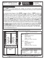
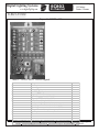
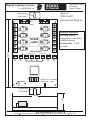
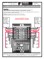
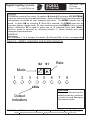
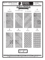
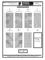
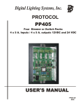
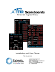
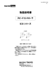
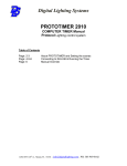
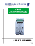
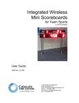
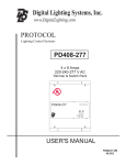
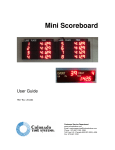
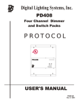
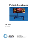
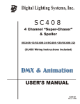
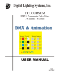
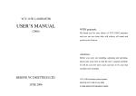
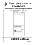
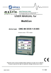
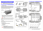
Digital Lighting Systems, Inc.
SC802
8 Channel “Mini-Fader/ Chaser ”
Cross Fader/ color mixing/ Animation chaser
SC802-12DC / SC802-24DC
DMX512 & Animation controllers
USER'S MANUAL
SC802-UM
10/15
Digital Lighting Systems
User's Manual - Page 1
16 Pattern
Fader / Chaser 1
SC802
www.digitallighting.com
8 channel
General Description
The SC802 is an Eight channel DC voltage only controller (Cross-Fader/Lighting
animation) capable of producing slow level changes( Color Mixing ) as well as Quick ON/
OFF ( Animation)
A functional block diagram of the SC802 is shown in Figure 1. SC802 contains the
equivalent of 2 sets of four solid-state relays (SSR) 8 dimmers, with two power line
feed. Each dimmer is rated at a maximum output current of 2.5 Amperes. The SSR
dimmers are controlled by low-voltage DC signals from the logic circuit on the board.
These signals are electrically-isolated by Optical couplers from all line voltage
elements. The SC802 logic board contains a microprocessor programmed to generate
16 user-selectable light sequences or patterns at an adjustable rate (the SC802 is also
available with a “SPELLER” pattern or custom patterns upon request). A rotary selector
is used to select the pattern and a second one is used to set the rate or speed. Patterns
and speed can be monitored by Eight LED's that represent the outputs of the SC802.
The SC802-12DC accepts two inputs from two 12 VDC power supplies 10Amps each.
The SC802-24DC accepts two inputs from two 24 VDC power supplies 10Amps each.
Please contact the factory for additional information by telephone 1-305-969-8442 or
email [email protected]
- +
- +
SSR6
SSR3
SSR7
SSR4
SSR8
6
SSR2
NAME
1,2,3,4
N1
P1
7
2 3 4
SSR5
Table 1 - Terminals Definition
5,6,7,8
8
N1 P1 P1 1
SSR1
5 P2 P2 N2
Figure 1 - SC802 Functional Block Diagram
N2
P2
DESCRIPTION
Output Of
Solid-State Relays #1,2,3,4
negative Feed For
Relays 1 , 2 , 3 & 4.
positive feed / Common Connections.
Output Of
Solid-State Relays #5,6,7,8
negative Feed For
Relays 5 , 6 , 7 & 8.
positive feed / Common Connections.
SSR's OPTICAL ISOLATORS
SC Logic Control
section
12302 SW 128th ct,UNIT 105, Miami, Fl. 33186
Copyright
Table 2 - Maximum Electrical Ratings
Electrical Characteristic Terminal
Relay Load Current
1 to 8
Input Current
P1,P2
Input Voltage depends on model
Tel: 305-969-8442
Fax: 305-969-8675
Maximum
2.5 Amps.
10 Amps.
12VDC or 24VDC
www.digitallighting.com
2015 Digital Lighting Systems, All rights Reserved Specifications are subject to change without notice. Printed in U.S.A.
Digital Lighting Systems
SC802
www.digitallighting.com
8 channel
User's Manual - Page 2
16 Pattern
Fader / Chaser 1
SC802-120 Detail
Figure 2 - SC802-xxDC
9
8
12
11
7
6
2
3
4
1
10
S2 S1
5
J1
Table 3 - SC802-XXDC Circuit Legend
1
2
3
4
5
6
7
8
9
10
11
12
J1
Microprocessor.
Not Used
Quartz Crystal.
Voltage Regulator.
Power Supply Capacitor.
Output LED Monitors.
Optical Couplers # 1,2,3,4,5,6,7,8
output MOSFETs # 1,2,3,4,5,6,7,8
Fuses 5mm, 10Amps
3 to 8 channel jumper selection
Input/ Outputs connection block for ch:1,2,3,4
Input/ Outputs connection block for ch:5,6,7,8
Jumper for crossfade and chase
S1
S2
Speed selector
Pattern Selector
12302 SW 128th ct,UNIT 105, Miami, Fl. 33186
Copyright
0 = Slowest ; F = fastest
Tel: 305-969-8442
Fax: 305-969-8675
www.digitallighting.com
2015 Digital Lighting Systems, All rights Reserved Specifications are subject to change without notice. Printed in U.S.A.
Digital Lighting Systems
User's Manual - Page 3
16 Pattern
Fader / Chaser 1
SC802
www.digitallighting.com
8 channel
Figure 3 SC802-xxDC
Dimensional Diagram
Mounting hole
For # 6 screw
10 A.
Fuse
Ch:
1
Ch:
5
Ch:
2
Ch:
6
SC802
-xxDC
Ch:
3
The SC802 modules
are designed to be mounted
in NEMA enclosures
Mounting Holes : 7” O.C.
( by others).
Ch:
7
Ch:
4
6.25 in
Mechanical Installation
Ch:
8
Optocouplers
1
2
3
4
5
6
7
8
Channel Indicators
Microprocessor
3 456
3 456
78
9A
F 0 12
9A
DE
BC
78
DE
BC
F 0 12
S2
S1
Jumper OFF = crossfade
Jumper ON = Chase
Mounting hole
For # 6 screw
1.50 in
4.30 in
12302 SW 128th ct,UNIT 105, Miami, Fl. 33186
Copyright
Tel: 305-969-8442
Fax: 305-969-8675
www.digitallighting.com
2015 Digital Lighting Systems, All rights Reserved Specifications are subject to change without notice. Printed in U.S.A.
Digital Lighting Systems
www.digitallighting.com
User's Manual - Page4
16 Pattern
Fader / Chaser 1
SC802
8 channel
Figure 4 - SC802-12DC & SC802-24DC Typical 12 VDC or 24 VDC Wiring.
Wiring Notes
0 DO NOT EXCEED 120W @ 24 VDC or 60 W @ 12 VDC (5 Amps.Max ) per switch output ;
total per each set of 4 outputs 240 W @24 VDC / 120 W @ 12 VDC ( 10 Amps)
0 All wiring between the controller and other switchs (DATA bus) is low voltage (NEMA Class 2) and may be run
with One, twisted pair, shielded #22 AWG wire.
0 SC802 switch Modules may be fed by 2 Class 2 Power supplies
0 CAUTION: DO NOT attempt to parallel outputs to increase capacity.
POWER
SUPPLY
12 VDC or
24 VDC
10 A. Max
+
- Negative
Negative Positive
Positive
Common +
-1
+ 1
POWER
SUPPLY
12 VDC or
24 VDC
10 A. Max
Common POSITIVE ( Anode )
Switched Negative (cathode)
Common +
5-
-2
-3
-4
6-
78-
- +
5
+ 2
- +
6
+ 3
- +
7
+ 4
- +
8
12302 SW 128th ct,UNIT 105, Miami, Fl. 33186
Copyright
+
Tel: 305-969-8442
Fax: 305-969-8675
www.digitallighting.com
2015 Digital Lighting Systems, All rights Reserved Specifications are subject to change without notice. Printed in U.S.A.
Digital Lighting Systems
User's Manual - Page 5
16 Pattern
Fader / Chaser 1
SC802
www.digitallighting.com
8 channel
Controls
The controls consist of two rotary 16-position (0-9 and A-F) selectors. S2 (PATTERN)
is used for selecting the desired Fade pattern. Positions 0 will scroll threw the patterns
automatically to provide an ever changing light show. The SC802 outputs can be
turned to static ON by selecting F. When 0 is selected, the SC802 goes into an
automatic pattern change mode. All other positions cause the SC802 to play a single
pattern indefinitely. S1 is used to select one of 16 individual Fade rates (Rate).
Minimum speed is achieved by selecting position 0. Speed doubles with each
subsequent selector position.
Indicators
LED indicators 1 to 4 indicate the status (On-Dimmed-Off) of their corresponding
Figure 5- SC802 Indicators and Control Selectors
S2
Rate
S1
Mode
1
2
3
4
5
6
7
8
LEDs
CAUTION
Use a small Screw driver for
adjusting selector positions
in order to avoid damaging
the Selectors slots.
Output
Indicators
12302 SW 128th ct,UNIT 105, Miami, Fl. 33186
Copyright
Tel: 305-969-8442
Fax: 305-969-8675
www.digitallighting.com
2015 Digital Lighting Systems, All rights Reserved Specifications are subject to change without notice. Printed in U.S.A.
Digital Lighting Systems
SC802
www.digitallighting.com
8 channel
User's Manual - Page6
16 Pattern
Fader / Chaser 1
SC802 Patterns
(Continued on Page 9)
1
1
2
Light Chase
Fill & Swipe Forward
2
3
Circuits
4 5 6
7
3
Fill & Swipe Back
4
Light Bounce
8
Step 1:
Step 2:
Step 3:
Step 4:
Step 5:
Step 6:
Step 7:
Step 8:
Step 9:
Step 10:
Step 11:
Step 12:
Step 13:
Step 14:
Step 15:
Step 16:
5
6
Dark Bounce
Dark Chase
KEY:
12302 SW 128th ct,UNIT 105, Miami, Fl. 33186
Copyright
7
Flip-Flop
8
Flash All
ON
OFF
Tel: 305-969-8442
Fax: 305-969-8675
www.digitallighting.com
2015 Digital Lighting Systems, All rights Reserved Specifications are subject to change without notice. Printed in U.S.A.
Digital Lighting Systems
SC802
www.digitallighting.com
8 channel
User's Manual - Page 7
16 Pattern
Fader / Chaser 1
Patterns for SC802
9
Flash Light Fade
1
2
3
Circuits
4 5 6
7
A
B
Spring Forward
Spring Back
C
Flash Dark Fade
8
Step 1:
Step 2:
Step 3:
Step 4:
Step 5:
Step 6:
Step 7:
Step 8:
Step 9:
Step 10:
Step 11:
Step 12:
Step 13:
Step 14:
Step 15:
Step 16:
D
E
Crawl Forward
Crawl Back
F
ALL ON
0
AUTO
Automatic Cycle
of Patterns 1-F
4 x each
then repeat
KEY:
12302 SW 128th ct,UNIT 105, Miami, Fl. 33186
Copyright
ON
OFF
Tel: 305-969-8442
Fax: 305-969-8675
www.digitallighting.com
2015 Digital Lighting Systems, All rights Reserved Specifications are subject to change without notice. Printed in U.S.A.
LIMITED WARRANTY
Digital Lighting Systems, warrants to the purFader that its
products have been carefully manufactured and inspected and
are warranted to be free from defects of workmanship and
materials when used as intended. Any abuse or misuse contrary
to normal operation shall void this warranty.
Upon request, replacement unit(s) will be shipped as soon as
available. Unless immediate shipment of replacement
merchandise is requested, Digital Lighting Systems will not
ship replacement merchandise until defective merchandise is
received, inspected, and determined to be defective.
Digital Lighting Systems' obligation under this warranty shall be
limited to replacement or repair of any units as shall within one
year of date of invoice from Digital Lighting Systems, prove
defective; and Digital Lighting Systems shall not be liable for
any other damages, whether direct or consequential. The
implied warranties of merchantability and fitness for a
particular purpose are limited to the duration of the
expressed warranty. Some states do not allow the exclusion of
the limitation of incidental or consequential damages, so the
above limitation or exclusion may not apply to you. This
warranty gives you specific legal rights, you may also have other
legal rights which vary from state to state.
No labor charges in connection with warranty problems will
be reimbursed by Digital Lighting Systems without prior
written approval from the factory.
Digital Lighting Systems distributors and representatives have
no authority to change this warranty without written permission.
Digital Lighting Systems reserves the right to determine the
best method of correcting warranty problems.
Defective merchandise may be returned to Digital Lighting
Systems, prepaid, after prior notification has been given and
approval obtained for the return. To obtain prior approval for the
return of the defective items, contact your local Digital Lighting
Systems distributor, representative, or:
Digital Lighting Systems, Inc.
Attn: Customer Service Department
12302 SW 128th ct, Unit # 105
Miami, FL 33186
(305) 264-8391
Digital Lighting Systems, Inc.
12302 SW 128th ct, Unit# 105
Miami, FL 33186
www.digitallighting.com
Tel 305-969-8442
Fax 305-969-8675
Printed in U.S.A.
October 2015