1
Installation
Form M500 V6
500 SERIES
Process Controllers
5 0 0
Hardware Installation
and Modification
Manual
for Electronic Products
Series 531, 532,
535, 545, 555
Model 2
Installation Guide
M500 V6, JUNE 2005
500 Series
1
Installation
INTRODUCTION
This technical brochure provides hardware installation and modification instructions for our controllers:
Series 531, 532, 535, 545, and 555. Use these instructions with the following kits:
Display Assembly Kits
531-632 ............... 531 Display
532-632 ............... 532 Display
535-632 ............... 535 Display
545-634 ............... 545 Display
555-632 ............... 555 Display
Assembly
Assembly
Assembly
Assembly
Assembly
Kit
Kit
Kit
Kit
Kit
Output and Communications Module Kits
532-600 ............... 531, 532 Analog Module Kit
535-600* .............. Mechanical Relay Module Kit
535-601* .............. Milliamp Module Kit
535-602* .............. SSR Module Kit
535-603* .............. SSR Drive Module Kit
535-604* .............. Loop Power Module Kit
535-705* .............. RS-485 Communications Module Kit
Power Supply Kit
535-730* .............. 90 to 250VAC Power Supply Kit
535-732 ............... 24VAC/VDC Power Supply Kit
Mounting Kit
535-761* .............. Mounting Kit
Miscellaneous Kits
532-100 ............... 531, 532 Bypass Board Kit
535-188* .............. Rear Terminal Upgrade Kit
535-660 ............... 531, 532, 535, 545, 555 Jumper Kit
535-662* .............. Gasket Kit
(1 Panel Gasket, 1 Bezel Gasket)
535-763* .............. Bezel Retention Screw Kit
535-664* .............. Module Retention Kit
(Retention Plate and Tie Wrap)
535-665* .............. Module Retention Tie Wrap Kit
093-128* .............. Lithium Battery
*
EPROM Kits
531-740 ................ 531 EPROM Kit
532-740 ............... 532 EPROM Kit
535-741 ................ 535 EPROM Kit (RSP)
535-775 ............... 535 Profiler EPROM Kit (No RSP)
535-776 ............... 535 Profiler EPROM Kit (RSP)
535-740 ................ 535 EPROM Kit (No RSP)
545-740 ................ 545 EPROM Kit (No RSP)
545-741 ................ 545 EPROM Kit (RSP)
555-740 ................ 555 EPROM Kit
Microcontroller (MCU) Board Kits
535-731 ............... MCU Board Kit
545-733 ............... MCU Board Kit with CE Option
Option Board Kits
535-720 ............... 531, 532, 535, 545 Option Board Kit
(No Options)
535-721 ............... 531, 532, 535, 545 Option Board Kit
(Digital Inputs)
535-722 ............... 535, 545 Option Board Kit
(Slidewire Feedback)
535-723 ............... 535, 545 Option Board Kit
(Digital Inputs and Slidewire Feedback)
545-724 ............... 531, 532, 535, 545, 555 Option Board Kit
(RSP)
545-725 ............... 531, 532, 535, 545, 555 Option Board Kit
(Digital Inputs and RSP)
545-726 ............... 535, 545, 555 Option Board Kit
(Slidewire Feedback and RSP)
545-727 ............... 535, 545, 555 Option Board Kit
(Digital Inputs, Slidewire Feedback,
and RSP)
Universal Kit (can be used with all 500 Series Controllers)
HOW TO USE THIS MANUAL:
A.
CAUTION: Static discharge will cause damage to equipment. Always ground yourself with a wrist grounding
strap when handling electronics to prevent static discharge.
B.
Before removing or inserting any hardware on the controller, copy down all configuration parameters. Also,
replacing the battery, EPROM or MCU Board will erase parameter settings and they will need to be reset.
C. For all hardware adjustments, perform steps 1, 2 and 3.
D. Follow the guide and complete any additional steps as required by your particular application.
E.
Complete your hardware adjustments with steps 15, 16, 17, 18, 19 & 20.
EQUIPMENT
To make any hardware changes to the units, you will need the following equipment:
•
2
Wrist grounding strap
• Phillips screwdriver (#2)
•
Small flat blade screwdriver
• Wire cutters
•
I.C. Extractor (if changing the EPROM)
500 Series
Installation Guide
Installation
INSTRUCTIONS
To Disassemble the Unit
For any hardware modifications, disassemble the unit.
1. With power off, loosen four captive front screws with
a Phillips screwdriver. Remove the four screws.
one of the larger two boards from the Option
Board (Photo 4). Be careful not to bend the
connector pins. Separate the other board in the
same manner.
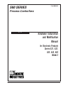
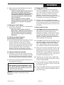
Figure 2 (opposite page) shows the Microcontroller
Board, Option Board and Power Supply Board.
To Add or Change Output Modules
The 500 Series units have provisions for four output
modules. The units come factory configured with
specified modules installed in appropriate locations.
You can make field modifications by properly removing and/or adding the modules into the appropriate
sockets.
Three of the output sockets are located on the Power
Supply Circuit Board. A fourth output socket is
located on the Option Board (refer to Figure 2).
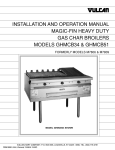
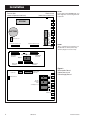
Figure 1
Location of Printed Circuit Boards for Hardware
Configuration
2. Slide the chassis out of the case by pulling on front
face plate assembly at the bezel (see Figure 1).
3. Locate the retention
clips holding the front
face assembly to the
rest of the chassis.
Pry apart these
retention clips gently
with a screwdriver to
separate the printed
circuit board group
from the front face
assembly (Photo 3).
Photo 3. Pry Clips
Take care not to
break the clips or
scratch the circuit board.
The Microcontroller Board and Power Supply Board
remain attached to the Operator Interface Assembly by wired connectors.
4. The Microcontroller
and Power Supply
board are attached
to either side of the
Option board by
male/female pin
connectors. Use a
gentle rocking motion
and carefully apply
pressure in a uniform
direction to separate
Installation Guide
5. A retention plate
and tie wrap hold
Output modules 1, 2,
and 3 (on the Power
Supply board) firmly
in place. To remove
the retention plate,
snip the tie wrap
with wire cutters
(Photo 5).
Photo 5.
Remove Retention Plate
CAUTION: Always snip the tie wrap on top of the
Retention Plate, as shown in photo 5, to prevent
damage to the surface mount components.
6. A disposable tie wrap
holds Output module
4 (on the Option
board) in place. To
remove the module,
snip the tie wrap
(Photo 6).
7. Inspect each module
before installation to
make sure the pins
are straight. Align
Photo 6.
the pins with the
socket holes and
Snip Tie Wrap on Mod. 4
carefully insert the
module. Press down on the module to seat it
firmly on the board.
Photo 4. Separate Boards
500 Series
3
Installation
Front of Unit
(toward Operator Interface)
Back of Unit
(toward rear terminals)
NOTE:
If you replace the EPROM chip, you
must align the notch facing the front
of the unit.
EPROM
TB2
5-Pin Connector
Female 22-Pin Connector
Female 22-Pin Connector
V
MA
TC
TC
RTD
PV1
BATTERY
2ND
V
MA
TC
TC
RTD
TB1
Male 22-Pin
Connector
Remote Setpoint Jumper
NOTE:
The 5- and 22-Pin connnectors on
the boards are all keyed so they
will only align one correct way.
Male 22-Pin
Connector
Output 4
22-Pin Female
Connector
NO J3 NC
12-Pin Female
Connector
Male 22-Pin
Connector
5-Pin Connector
Module
Retention
Plate
over Outputs 1,2,3
Figure 2
Microntroller Board,
Option Board, and
Power Supply Board
NO J1 NC NO J2 NC
Male 12-Pin
Connector
Jumpers
NO and NC
4
500 Series
Installation Guide
Installation
8. Replace tie wraps for the Retention Plate and for
Output Module 4 with new ones.
Failure to use these devices may result in a
loosening of the module and eventual
failure. If you ordered a module separately,
it should have come with a tie wrap. An
extra set of tie wraps is available by ordering Part #535-665.
Note: For greatest accuracy, milliamp
modules added for retransmission must be
calibrated per instructions in Operator's
Manual.
To Change the Option Board
9. (See Photos 3 and 4) Replace the existing Option
board with the NEW one.
Note: When adding Option board for 5
digital inputs, associated screw terminal in
the rear terminal block must be installed.
(See information on page 1 for ordering a
Screw Kit.)
To Change the Power Supply or
Microcontroller (CPU) Board
10. For the Microcontroller Board, disconnect the 5-pin
female connector that wires it to the Display
Assembly. Reattach the connector to the new
board. You can only orient the connector one way.
For the Power Supply Board, disconnect the 5-pin
female connector that wires it to the Display
Assembly. Reattach the connector to the new
board. You can only orient the connector one way.
To Change the Display Assembly
11. Disconnect the 5-pin female connector that wires
the Microcontroller Board to the Display Assembly.
Disconnect the 5-pin female connector that wires
the Power Supply Board to the Display Assembly.
12. Attach the new Display Assembly to the boards at
the appropriate connectors.
CAUTION
Static discharge will cause damage to equipment. Always ground yourself with a wrist
grounding strap when handling electronics
to prevent static discharge.
To Change the EPROM
13. The EPROM is located on the Microcontroller
Circuit board (Figure 2). It has a white label that
list the part number and software revision level.
Use an I.C. Extractor to carefully remove the
EPROM. If you do not have an I.C. extractor,
gently use a small flat blade screwdriver to pry up
the EPROM. DO Not bend the EPROM legs.
14. Carefully insert the new EPROM. To position
correctly, match the notched end of the EPROM to
the markings on the board. The notched end will
face towards the display. Make sure all pins are in
the socket.
To Reassemble the Unit
15. (See Figure 2) Align the connector pins on the
Option Board with the connector sockets on the
Microcontroller and Power Supply boards.
Squeeze them together, making certain all three
are properly seated against one another. Check
along the side edges for gaps. Make sure the
conector is properly aligned. Also, check that the
cable assemblies are not pinched.
16. (See Figure 2) Align the board assembly with the
front face assembly, with the Option board at the
bottom (see Figure 1). Reinstall the retention
clips. Align the boards into the slots of the front
face assembly and the clips will snap into place.
17. When you are ready to reassemble the unit, align
the boards in the chassis with the case's top and
bottom grooves. Press firmly to slide the chassis
into the case. If you have difficulty, check that you
have properly oriented the chassis, and there are
no screws interfering with the case.
18. Carefully insert and align screws. Tighten them
until the bezel is seated firmly against the gasket.
DO NOT OVERTIGHTEN.
19. If may be necessary to re-configure the software
features of your controller or station. Please refer
to your User’s Manual.
20. To maintain NEMA 4X Rating, you may need new
mounting gaskets, order part #535-662. Refer to
your user’s manual.
CAUTION
Do not scratch the boards or bend the pins of the
connectors.
Installation Guide
500 Series
5
Declaration of Conformity
EMC Directive 89/336/EEC
Manufacturer’s Name:
Manufacturer’s Address:
Moore Industries-International, Inc.
16650 Schoenborn Street
North Hills, CA 91343-6196
USA
Declares that the product(s):
Product Name:
500 Series
MODEL
Model Number(s):
500 Series
/
INPUT
*
/
OUTPUT
/
*
POWER
24 Vdc
/
OPTIONS
/
HOUSING
** H or J
*Indicates any input, output, option and housing as stated on the product data sheet.
**Indicates CE Compliant.
Conforms to the following EMC specifications:
EN61326-1, 1998, Electromagnetic Compatibility requirements for electrical equipment for control use.
Conforms to the following safety standard:
EN 61010-1, 2001
Supplemental Information:
CE option requires CE KIT PN 535-766.
Janurary 9, 2003
Date
______________________________
Fred Adt
Quality Assurance Director
_____________________________________
Robert Stockham
Moore Industries-International, Inc.
European Contact: Your Local Moore Industries Sales and Service Office
*
Declaration of Conformity
EMC Directive 89/336/EEC
Manufacturer’s Name:
Manufacturer’s Address:
Moore Industries-International, Inc.
16650 Schoenborn Street
North Hills, CA 91343-6196
USA
Declares that the product(s):
Product Name:
500 Series
MODEL
Model Number(s):
500 Series
/ INPUT / OUTPUT /
*
*
POWER
Universal Power
Supply
/
OPTIONS
/
** H or J
HOUSING
*
*Indicates any input, output, option and housing as stated on the product data sheet.
**Indicates CE Compliant.
Conforms to the following EMC specifications:
EN61326-1, 1998, Electromagnetic Compatibility requirements for electrical equipment for control use.
Conforms to the following safety standard:
EN 61010-1, 2001
Supplemental Information:
CE option requires CE KIT PN 535-765.
August 15, 2005
Date
______________________________
_____________________________________
Fred Adt
Quality Assurance Director
Robert Stockham
Moore Industries-International, Inc.
European Contact: Your Local Moore Industries Sales and Service Office
RETURN PROCEDURES
To return equipment to Moore Industries for repair, follow these four steps:
1. Call Moore Industries and request a Returned Material Authorization (RMA) number.
Warranty Repair –
If you are unsure if your unit is still under warranty, we can use the unit’s serial number
to verify the warranty status for you over the phone. Be sure to include the RMA
number on all documentation.
Non-Warranty Repair –
If your unit is out of warranty, be prepared to give us a Purchase Order number when
you call. In most cases, we will be able to quote you the repair costs at that time.
The repair price you are quoted will be a “Not To Exceed” price, which means that the
actual repair costs may be less than the quote. Be sure to include the RMA number on
all documentation.
2. Provide us with the following documentation:
a) A note listing the symptoms that indicate the unit needs repair
b) Complete shipping information for return of the equipment after repair
c) The name and phone number of the person to contact if questions arise at the factory
3. Use sufficient packing material and carefully pack the equipment in a sturdy shipping
container.
4. Ship the equipment to the Moore Industries location nearest you.
The returned equipment will be inspected and tested at the factory. A Moore Industries
representative will contact the person designated on your documentation if more information is
needed. The repaired equipment, or its replacement, will be returned to you in accordance with
the shipping instructions furnished in your documentation.
WARRANTY DISCLAIMER
THE COMPANY MAKES NO EXPRESS, IMPLIED OR STATUTORY WARRANTIES (INCLUDING ANY WARRANTY OF MERCHANTABILITY OR OF FITNESS
FOR A PARTICULAR PURPOSE) WITH RESPECT TO ANY GOODS OR SERVICES SOLD BY THE COMPANY. THE COMPANY DISCLAIMS ALL WARRANTIES ARISING FROM ANY COURSE OF DEALING OR TRADE USAGE, AND
ANY BUYER OF GOODS OR SERVICES FROM THE COMPANY ACKNOWLEDGES THAT THERE ARE NO WARRANTIES IMPLIED BY CUSTOM OR
USAGE IN THE TRADE OF THE BUYER AND OF THE COMPANY, AND THAT
ANY PRIOR DEALINGS OF THE BUYER WITH THE COMPANY DO NOT IMPLY THAT THE COMPANY WARRANTS THE GOODS OR SERVICES IN ANY
WAY.
ANY BUYER OF GOODS OR SERVICES FROM THE COMPANY AGREES
WITH THE COMPANY THAT THE SOLE AND EXCLUSIVE REMEDIES FOR
BREACH OF ANY WARRANTY CONCERNING THE GOODS OR SERVICES
SHALL BE FOR THE COMPANY, AT ITS OPTION, TO REPAIR OR REPLACE
THE GOODS OR SERVICES OR REFUND THE PURCHASE PRICE. THE
COMPANY SHALL IN NO EVENT BE LIABLE FOR ANY CONSEQUENTIAL OR
INCIDENTAL DAMAGES EVEN IF THE COMPANY FAILS IN ANY ATTEMPT
TO REMEDY DEFECTS IN THE GOODS OR SERVICES , BUT IN SUCH CASE
THE BUYER SHALL BE ENTITLED TO NO MORE THAN A REFUND OF ALL
MONIES PAID TO THE COMPANY BY THE BUYER FOR PURCHASE OF THE
GOODS OR SERVICES.
ANY CAUSE OF ACTION FOR BREACH OF ANY WARRANTY BY THE
COMPANY SHALL BE BARRED UNLESS THE COMPANY RECEIVES
FROM THE BUYER A WRITTEN NOTICE OF THE ALLEGED DEFECT OR
BREACH WITHIN TEN DAYS FROM THE EARLIEST DATE ON WHICH THE
BUYER COULD REASONABLY HAVE DISCOVERED THE ALLEGED DEFECT OR BREACH, AND NO ACTION FOR THE BREACH OF ANY WARRANTY SHALL BE COMMENCED BY THE BUYER ANY LATER THAN
TWELVE MONTHS FROM THE EARLIEST DATE ON WHICH THE BUYER
COULD REASONABLY HAVE DISCOVERED THE ALLEGED DEFECT OR
BREACH.
RETURN POLICY
For a period of thirty-six (36) months from the date of shipment, and under
normal conditions of use and service, Moore Industries ("The Company") will
at its option replace, repair or refund the purchase price for any of its manufactured products found, upon return to the Company (transportation charges
prepaid and otherwise in accordance with the return procedures established
by The Company), to be defective in material or workmanship. This policy
extends to the original Buyer only and not to Buyer's customers or the users
of Buyer's products, unless Buyer is an engineering contractor in which case
the policy shall extend to Buyer's immediate customer only. This policy shall
not apply if the product has been subject to alteration, misuse, accident, neglect or improper application, installation, or operation. THE COMPANY
SHALL IN NO EVENT BE LIABLE FOR ANY INCIDENTAL OR CONSEQUENTIAL DAMAGES.
United States • [email protected]
Tel: (818) 894-7111 • FAX: (818) 891-2816
Australia • [email protected]
Tel: (02) 8536-7200 • FAX: (02) 9525-7296
© 2006 Moore Industries-International, Inc.
Belgium • [email protected]
Tel: 03/448.10.18 • FAX: 03/440.17.97
The Netherlands • [email protected]
Tel: (0)344-617971 • FAX: (0)344-615920
China • [email protected]
Tel: 86-21-62491499 • FAX: 86-21-62490635
United Kingdom • [email protected]
Tel: 01293 514488 • FAX: 01293 536852
Specifications and Information subject to change without notice.


![ECT[DIN] [DIN] - Moore Industries International](http://vs1.manualzilla.com/store/data/005778735_1-93255c4f7d497ff32afcfe496e72d982-150x150.png)