1
JTLS Document 17
JTLS
Version Description Document
February 2006
U.S. Joint Forces Command
Joint Warfighting Center
116 Lake View Parkway
Suite 100
Suffolk, VA 23435-2697
JOINT THEATER LEVEL SIMULATION
(JTLS 3.1.0.0)
February 2006
JTLS Document 17
ABSTRACT
This JTLS Version Description Document (VDD) describes Version 3.1.0.0 of the configured
software suite identified as the Joint Theater Level Simulation (JTLS). JTLS 3.1.0.0 is a Major
release.
As a Major release, JTLS 3.1.0.0 includes a modified and enhanced Standard Database, as well as
extensive model functionality changes implemented as Enhancement Change Proposals (ECPs).
These ECPs are described in Chapter 2. Chapter 3 of this document describes the code modifications
that represent corrections to Software Trouble Reports (STRs). The remaining outstanding STRs are
described in Chapter 4.
This publication is updated and revised for each version release of the JTLS model. User corrections,
additions, or constructive recommendations for improvement must include justification and be
referenced to specific sections, pages, and paragraphs. Submissions must be written in Model Change
Request (MCR) format and forwarded to:
JTLS Configuration Management Agent
JFCOM/JWFC
116 Lake View Parkway
Test Bay 28
Suffolk, VA 23435-2697
Copyright 2005, ROLANDS & ASSOCIATES Corporation
JTLS 3.1.0.0
iii
Version Description Document
JTLS Document 17
February 2006
[Blank Page]
Version Description Document
iv
JTLS 3.1.0.0
February 2006
JTLS Document 17
TABLE of CONTENTS
1.0 INTRODUCTION
1.1 SCOPE .......................................................................................................................... 1-1
1.2 INVENTORY OF MATERIALS ................................................................................. 1-1
1.2.1 Obsolete/Outdated Documents ............................................................................ 1-1
1.2.2 Unchanged Documents ........................................................................................ 1-2
1.2.3 Updated Documents ............................................................................................. 1-2
1.2.4 New Documents ................................................................................................... 1-2
1.2.5 Released Software ................................................................................................ 1-2
1.2.6 Released Databases .............................................................................................. 1-3
1.3 INTERFACE COMPATIBILITY ................................................................................ 1-4
1.3.1 Support Software ................................................................................................. 1-4
1.3.2 HLA Compliance ................................................................................................. 1-5
1.3.3 Web Enabled Interface ......................................................................................... 1-6
1.4 INSTALLATION CONSIDERATIONS ...................................................................... 1-6
1.5 DATABASE MODIFICATIONS ................................................................................. 1-6
1.5.1 Interactive Database Upgrade .............................................................................. 1-6
1.5.2 Data Elements .................................................................................................... 1-10
1.5.3 Standard Database Changes ............................................................................... 1-17
1.6 INSTALLATION NOTES .......................................................................................... 1-17
1.6.1 Installation Instructions ...................................................................................... 1-17
1.6.2 GIAC Compatibility .......................................................................................... 1-18
1.6.3 Oracle Compatibility and Installation ................................................................ 1-18
2.0 ENHANCEMENT CHANGE PROPOSALS
2.1 JTLS-0028 NAMED MAP VIEWS .............................................................................. 2-1
2.1.1 Summary of Model Change Request ................................................................... 2-1
2.1.2 Design Summary .................................................................................................. 2-1
2.2 JTLS-0050 NEW SQUADRON SITREP ..................................................................... 2-4
2.2.1 Summary of Model Change Request ................................................................... 2-4
2.2.2 Design Summary .................................................................................................. 2-4
2.3 JTLS-0051 MULTIPLE ACO PROCESSING ............................................................. 2-5
2.3.1 Summary of Model Change Request ................................................................... 2-5
2.3.2 Design Summary .................................................................................................. 2-5
2.4 JTLS-0082 PASS AIRCRAFT TYPE CHANGES TO PLAYER GIACS .................. 2-6
2.4.1 Summary of Model Change Request ................................................................... 2-6
2.4.2 Design Summary .................................................................................................. 2-6
2.5 JTLS-0124 CHANGE CEP PORT WITHIN ICP ........................................................ 2-6
2.5.1 Summary of Model change Request .................................................................... 2-6
2.5.2 Design Summary .................................................................................................. 2-6
2.6 JTLS-0150 IFF IMPROVEMENT ............................................................................... 2-6
JTLS 3.1.0.0
v
Version Description Document
JTLS Document 17
February 2006
2.6.1 Summary of Model Change Request ................................................................... 2-6
2.6.2 Design Summary .................................................................................................. 2-7
2.7 JTLS-0154 TARGET FILTERING ............................................................................ 2-15
2.7.1 Summary of Model Change Request ................................................................. 2-15
2.7.2 Design Summary ................................................................................................ 2-15
2.7.3 Data Changes ..................................................................................................... 2-23
2.8 JTLS-0277 TARGET UNDERGROUND FLAG ...................................................... 2-24
2.8.1 Summary of Model Change Request ................................................................. 2-24
2.8.2 Design Summary ................................................................................................ 2-24
2.8.3 Data Changes ..................................................................................................... 2-27
2.8.4 Order Changes ................................................................................................... 2-27
2.8.5 FOM Changes .................................................................................................... 2-28
2.9 JTLS-0312 USER LINES ON MAP DISPLAYS ...................................................... 2-28
2.10 JTLS-0320 UTM/MGRS CONVERSION UTILITY ............................................... 2-29
2.10.1 Summary of Model Change Request ............................................................... 2-29
2.10.2 Design Summary .............................................................................................. 2-29
2.11 JTLS-0333 SEND GROUP ORDERS ...................................................................... 2-30
2.11.1 Summary of Model Change Request ............................................................... 2-30
2.11.2 Design Summary .............................................................................................. 2-30
2.12 JTLS-0334 DISPLAY COMPLETED MISSIONS .................................................. 2-33
2.12.1 Summary of Model Change Request ............................................................... 2-33
2.12.2 Design Summary .............................................................................................. 2-34
2.13 JTLS-0343 SORT MESSAGES BY UNIT /FACTION ........................................... 2-34
2.13.1 Summary of Model Change Request ............................................................... 2-34
2.13.2 Design Summary .............................................................................................. 2-35
2.14 JTLS-0347 UNITS IN COMBAT FLAG ................................................................. 2-36
2.14.1 Summary of Model Change Request ............................................................... 2-36
2.14.2 Design Summary .............................................................................................. 2-36
2.15 JTLS-0358 COLOR UNITS BY SUPPLY LEVEL ................................................. 2-37
2.15.1 Summary of Model Change Request ............................................................... 2-37
2.15.2 Design Summary .............................................................................................. 2-37
2.16 JTLS-0397 AIR MISSION SPEED FLEXIBILITY ................................................. 2-40
2.16.1 Summary of Model Change Request ............................................................... 2-40
2.16.2 Design Summary .............................................................................................. 2-40
2.16.3 Data Changes ................................................................................................... 2-43
2.16.4 Order Changes ................................................................................................. 2-43
2.17 JTLS-0398 PROCESS ATO-T CHANGES ............................................................. 2-43
2.17.1 Summary of Model Change Request ............................................................... 2-43
2.17.2 Design Summary .............................................................................................. 2-44
2.18 JTLS-0403 EXTERNAL GRAPHICS FILE ............................................................ 2-45
2.18.1 Summary of Model Change Request ............................................................... 2-45
2.18.2 Design Summary .............................................................................................. 2-45
2.19 JTLS-0411 MANUAL PAIR PROTECTION RADIUS OVERRIDE ..................... 2-46
Version Description Document
vi
JTLS 3.1.0.0
February 2006
JTLS Document 17
2.19.1 Summary of Model Change Request ............................................................... 2-46
2.20 JTLS-0442 DETACHED SQUADRON MAINTENANCE .................................... 2-46
2.20.1 Summary of Model Change Request ............................................................... 2-46
2.20.2 Malfunction Maintenance Model ..................................................................... 2-47
2.20.3 Data Changes ................................................................................................... 2-50
2.20.4 Order Changes ................................................................................................. 2-50
2.21 JTLS-0501 AAR IMPROVEMENTS ....................................................................... 2-50
2.21.1 Summary of Model Change Request ............................................................... 2-50
2.22 JTLS-0521 LINK JTLS TO TBMCS ....................................................................... 2-51
2.22.1 Summary of Model Change Request ............................................................... 2-51
2.22.2 Available Data ................................................................................................. 2-52
2.23 JTLS-0522 LINK JTLS TO JDLM ........................................................................... 2-52
2.23.1 Summary of Model Change Request ............................................................... 2-52
2.23.2 Design Summary .............................................................................................. 2-54
2.24 JTLS-0525 ENTITY LEVEL SIMULATION .......................................................... 2-55
2.24.1 Summary of Model Change Request ............................................................... 2-55
2.24.2 Design Summary .............................................................................................. 2-57
2.25 JTLS-0540 MAGIC REPLENISH AIR MISSION .................................................. 2-58
2.25.1 Summary of Model Change Request ............................................................... 2-58
2.25.2 Design Summary .............................................................................................. 2-58
2.25.3 Order Changes ................................................................................................. 2-59
2.26 JTLS-0554 MULTIPLE UNITS OF MEASURE ..................................................... 2-59
2.26.1 Summary of Model Change Request ............................................................... 2-59
2.26.2 Design Summary .............................................................................................. 2-59
2.27 JTLS-2005-1409 LINK JTLS TO MDST ................................................................. 2-61
2.27.1 Summary of Model Change Request ............................................................... 2-61
2.27.2 Design Summary .............................................................................................. 2-62
2.27.3 Data Changes ................................................................................................... 2-65
2.28 JTLS-2005-1480 LIFEBOAT REPRESENTATION ............................................... 2-66
2.28.1 Summary of Model Change Request ............................................................... 2-66
2.28.2 Design Summary .............................................................................................. 2-66
2.28.3 Data Changes ................................................................................................... 2-69
2.28.4 Order Changes ................................................................................................. 2-69
2.29 JTLS-2005-1484 TANKER STAY ON ORBIT ....................................................... 2-70
2.29.1 Design Summary .............................................................................................. 2-70
2.30 JTLS-2005-1535 WHIP ICON SIZE SELECTION ................................................. 2-70
2.30.1 Summary of Model Change Request ............................................................... 2-70
2.30.2 Design Summary .............................................................................................. 2-70
2.30.3 Order Changes ................................................................................................. 2-76
2.31 JTLS-2005-1536 MODEL RUNWAY DIRECTION .............................................. 2-76
2.31.1 Summary of Model Change Request ............................................................... 2-76
2.31.2 Publishing Supply Commitment Information .................................................. 2-79
2.31.3 Data Changes ................................................................................................... 2-79
JTLS 3.1.0.0
vii
Version Description Document
JTLS Document 17
February 2006
2.31.4 Order Changes ................................................................................................. 2-80
2.32 JTLS-2005-1537 TEMPLATE CREATION TOOL ................................................ 2-80
2.32.1 Summary of Model Change Request ............................................................... 2-80
2.33 JTLS-2005-1538 IMPROVED NAVAL DAMAGE ................................................ 2-80
2.33.1 Summary of Model Change Request ............................................................... 2-80
2.33.2 Data Changes ................................................................................................... 2-86
2.33.3 Order Changes ................................................................................................. 2-86
2.34 JTLS-2005-1539 IMPROVE FUEL REQUIRED DECISION ................................ 2-86
2.34.1 Summary of Model Change Request ............................................................... 2-86
2.35 JTLS-2005-1540 IMT SEARCH CAPABILITY ..................................................... 2-86
2.35.1 Summary of Model Change Request ............................................................... 2-86
2.36 JTLS-2005-1549 JTLS-RTM INTEGRATION ....................................................... 2-88
2.36.1 Summary of Model Change Request ............................................................... 2-88
2.36.2 Design Summary .............................................................................................. 2-88
2.37 JTLS-2005-1551 TBMCS IMPROVEMENTS ........................................................ 2-89
2.37.1 Design Summary .............................................................................................. 2-89
2.37.2 Order Changes ................................................................................................. 2-95
2.38 JTLS-2005-1552 REDUCE LANCHESTER DATA ............................................... 2-96
2.38.1 Summary of Model Change Request ............................................................... 2-96
2.38.2 Design Summary .............................................................................................. 2-96
2.38.3 Data Changes ................................................................................................. 2-100
2.39 JTLS-2005-1556 WEAPON LOAD RECOGNITION ........................................... 2-101
2.40 JTLS-2005-1557 MAINTAIN FEDERATION IF CEP GOES DOWN ................ 2-102
2.40.1 Design Summary ............................................................................................ 2-102
2.41 JTLS-2005-1578 PASSING CONTROL OF PROBLEMATIC ARUS ................. 2-107
2.41.1 Summary of Model Change Request ............................................................. 2-107
2.41.2 Design Summary ............................................................................................ 2-107
2.42 JTLS-2005-1596 CORRECT USMTF AIR MISSION REPORTS ....................... 2-109
2.42.1 Summary of Model Change Request ............................................................. 2-109
2.42.2 Design Summary ............................................................................................ 2-109
2.42.3 Data Changes ................................................................................................. 2-109
2.43 JTLS-0011 DEFAULT STATUS FOR HRU: COVERT UNIT REPORT ........... 2-109
2.44 JTLS-0065 INCLUDE WHETHER STATION IS TRUE OR RELATIVE ......... 2-110
2.45 JTLS-0122 SEARCH MPP MESSAGE TEXT FOR STRINGS .......................... 2-110
2.46 JTLS-0146 SETTING DESERT COLOR ............................................................. 2-110
2.47 JTLS-0164 VARIABLES AND JTLS RESTRICTED TERRAIN COLORS ...... 2-110
2.48 JTLS-0183 GENIS CLIENT REPORT HOST NAME REPORT ......................... 2-111
2.49 JTLS-0188 PROVIDE MPP ERROR MESSAGES FOR BAD STRINGS .......... 2-111
2.50 JTLS-0292 EXPAND COMMAND AUTHORITY REPORT ............................. 2-111
2.51 JTLS-0303 ALLOW MODEL TO REFUSE CLIENT CONNECTIONS ............ 2-111
2.52 JTLS-0319 JTLS PLAYBOX OUTLINE .............................................................. 2-112
2.53 JTLS-0444 UOM DISTANCE OPTION ............................................................... 2-112
2.54 JTLS-2005-1639 ADD SPEED TO HRU IMT PANEL ....................................... 2-112
Version Description Document
viii
JTLS 3.1.0.0
February 2006
JTLS Document 17
3.0 SOFTWARE TROUBLE REPORTS
3.1 INTRODUCTION ........................................................................................................ 3-1
3.2 ERRORS CORRECTED FOR THIS RELEASE ......................................................... 3-1
3.2.1 JTLS-0951 Air Missions Flying Backwards ........................................................ 3-1
3.2.2 JTLS-2006-1641 Unable To Cancel Holding Posture Missions .......................... 3-2
3.2.3 JTLS-2006-1663 NFS-Mounted File System Makefile Errors ............................ 3-2
3.2.4 JTLS-2006-1684 Crash Changing Air Mission Package Ingress Route .............. 3-2
3.2.5 JTLS-2006-1687 Incorrect Associated Unit On Air-Ground Attack Mission ..... 3-2
3.2.6 JTLS-2006-1688 Inconsistent Track ID Between JODA And GENIS ............... 3-3
3.2.7 JTLS-2006-1689 Aircraft Maintenance Records Not Deleted From IMT .......... 3-3
3.2.8 JTLS-2006-1690 Unable To Extend Aircraft Maintenance Times ...................... 3-3
3.2.9 JTLS-2006-1691 Missing Spaces In Message Strings ......................................... 3-4
3.2.10 JTLS-2006-1692 Unable To Change Transfer Aircraft Egress Route ............... 3-4
3.2.11 JTLS-2006-1693 Situation Report Truncated Location Coordinates ................ 3-4
3.2.12 JTLS-2006-1694 Missing Convoy Problem Report Sylesheet .......................... 3-4
3.2.13 JTLS-2006-1695 JODA Version SDC Used Modified Table Names ............... 3-5
3.2.14 JTLS-2006-1722 Improper Argument Modes In Routine Calls ........................ 3-5
4.0 REMAINING ERRORS
4.1 INTRODUCTION ........................................................................................................ 4-1
4.2 REMAINING ERRORS ............................................................................................... 4-1
4.2.1 JTLS-0639 Error Determining When Engineering Task Completed .................. 4-1
4.2.2 JTLS-0695 Shadow Distance Of Zero Overriding Protection Radius ................. 4-1
4.2.3 JTLS-0696 Missions Ignoring Assigned Altitude on Egress ............................... 4-2
4.2.4 JTLS-0697 Missions On The Ground With Invalid Destination ......................... 4-2
4.2.5 JTLS-0698 Cannot Re-Activate Destroyed Targets ............................................ 4-2
4.2.6 JTLS-0699 Targets That Require An Owner Are Disassociated ......................... 4-2
4.2.7 JTLS-0700 GIAC Not Displaying Current Runway Length ............................... 4-2
4.2.8 JTLS-0701 Air Movement Report Does Not Consider Hold Points ................... 4-2
4.2.9 JTLS-0702 Mission Waiting For Delayed Mission ............................................. 4-2
4.2.10 JTLS-0703 Periodic Report Other Side Airbases Lists No Activity ................. 4-3
4.2.11 JTLS-0704 Immediate Cancel Of Air Mission in Delay Status ........................ 4-3
4.2.12 JTLS-0705 Missions Launching With Fewer Aircraft Than Available ............. 4-3
4.2.13 JTLS-0843 Error 427 ......................................................................................... 4-3
4.2.14 JTLS-0846 Naval Unit Distance Calculation .................................................... 4-3
4.2.15 JTLS-0865 Incorrect External Program Order .................................................. 4-4
4.2.16 JTLS-0869 Continue Engage Determination ..................................................... 4-4
4.2.17 JTLS-0870 Number of Air-to-Air Combat Kills Allowed ................................ 4-4
4.2.18 JTLS-0871 AC Mission Weapon Drop Determination ..................................... 4-4
4.2.19 JTLS-0906 Change ADA pE To Per-Element pE ............................................. 4-4
4.2.20 JTLS-0907 Scud-Like SSM Representation ...................................................... 4-5
4.2.21 JTLS-0908 Naval IADS Link Representation ................................................... 4-5
4.2.22 JTLS-0909 Display Moderate And Severe Attrition Level ............................... 4-5
JTLS 3.1.0.0
ix
Version Description Document
JTLS Document 17
February 2006
4.2.23 JTLS-0910 HRU Patrol Intel Reports ................................................................ 4-6
4.2.24 JTLS-0911 Fire Artillery Wait Time Between Missions ................................... 4-6
4.2.25 JTLS-0928 Weapons Selection By Aircraft ...................................................... 4-6
4.2.26 JTLS-0929 Ship Changes Sides ......................................................................... 4-6
4.2.27 JTLS-0934 HRU Overwatch .............................................................................. 4-7
4.2.28 JTLS-0942 Air Transport Cannot Combine Wet And Dry Supplies ................. 4-7
4.2.29 JTLS-0948 Lanchester Double Kills ................................................................. 4-7
4.2.30 JTLS-0949 Destroyed Target SITREP Strength Incorrect ................................ 4-7
4.2.31 JTLS-0950 JTLS Radius Of Effects .................................................................. 4-7
4.2.32 JTLS-0952 Air Report ....................................................................................... 4-8
4.2.33 JTLS-0953 All Sides Informed About Supply Dump Error .............................. 4-8
4.2.34 JTLS-0954 Multiple Supply Storage Targets .................................................... 4-8
4.2.35 JTLS-0955 Air Lift Drop Report Message ........................................................ 4-8
4.2.36 JTLS-0956 MPP Messages For Canceled Missions In Error ............................ 4-8
4.2.37 JTLS-0957 Can’t Take Control Of Unowned Runways .................................... 4-8
4.2.38 JTLS-0958 Withdrawing Units Cannot Destroy Supply Targets ...................... 4-8
4.2.39 JTLS-0959 Logistics Report Problem ............................................................... 4-9
4.2.40 JTLS-0960 Can’t Magic Move Airbase To Existing Airbase Location ............ 4-9
4.2.41 JTLS-0961 Group Ground Move Delayed To Lead Unit .................................. 4-9
4.2.42 JTLS-0962 Pass Unit Intelligence Does Not Include Update Information ........ 4-9
4.2.43 JTLS-0963 IMT Supply Category Line Disappears When Value Is Zero ......... 4-9
4.2.44 JTLS-0964 Reporting Bridge Damage ............................................................ 4-10
4.2.45 JTLS-0965 Error In Time Report For SET SP CONVOY DELAYS ............. 4-10
4.2.46 JTLS-0966 Incorrect Mission Report Locations .............................................. 4-10
4.2.47 JTLS-0967 Fire Mission Not Deleted From GENIS ....................................... 4-10
4.2.48 JTLS-0968 Inconsistency Between Regular Run And Pusher ........................ 4-10
4.2.49 JTLS-0969 Changing Mission On Alert .......................................................... 4-11
4.2.50 JTLS-0970 Availability Of Aircraft ................................................................. 4-11
4.2.51 JTLS-0971 Ship Continuous Tracking Not Working ...................................... 4-11
4.2.52 JTLS-0972 Air Mission Find In Middle Of Ocean .......................................... 4-11
4.2.53 JTLS-0973 Periodic Report Air Supplies And Fuel Not Correct .................... 4-11
4.2.54 JTLS-0974 Submarine Detection By Ground Sensors .................................... 4-11
4.2.55 JTLS-0975 GDS Target Update Error ............................................................. 4-11
4.2.56 JTLS-0976 Manual Pairing And Protection Radius ........................................ 4-12
4.2.57 JTLS-0977 Slightly Inaccurate Runway Length Sometimes Used .................. 4-12
4.2.58 JTLS-0978 Air Missions Don't Completely Comply With Egress .................. 4-12
4.2.59 JTLS-0979 Halted Helo Squadrons Show “Mission” As MOVING ............... 4-12
4.2.60 JTLS-0980 SVP Warning 22 ........................................................................... 4-12
4.2.61 JTLS-0981 Formation With No Posture .......................................................... 4-12
4.2.62 JTLS-0982 GIAC Shows HRU Mission Moving After Move Complete ........ 4-13
4.2.63 JTLS-0983 IMT/GIAC Show Insert/Extract Mission Flying .......................... 4-13
4.2.64 JTLS-0984 IMT Doesn’t Add Unit Names ..................................................... 4-13
4.2.65 JTLS-0985 PSYOP Results Multiplier ............................................................ 4-13
Version Description Document
x
JTLS 3.1.0.0
February 2006
JTLS Document 17
4.2.66 JTLS-0987 Set Periodic Report Times ............................................................ 4-13
4.2.67 JTLS-0988 Can’t Repair Naval Catapults ....................................................... 4-14
4.2.68 JTLS-0989 Controller Damaged Aircraft Not In Periodic Reports ................. 4-14
4.2.69 JTLS-0993 Weapons Report on Mission Report ............................................. 4-14
4.2.70 JTLS-0994 HRU Creation Target Requirements Assessed Incorrectly .......... 4-14
4.2.71 JTLS-0999 Cancel Naval Mission Fails When A Unit Is Specified ................ 4-14
4.2.72 JTLS-1006 Clearing Player Orders Also Clears User Lines ........................... 4-14
4.2.73 JTLS-1010 Controller Cannot MM NEUTRAL Unit Onto Formation ........... 4-14
4.2.74 JTLS-1017 Airlift Mission Problem ................................................................ 4-15
4.2.75 JTLS-1090 GIAC Fields Allow Spaces ........................................................... 4-15
4.2.76 JTLS-1258 RECCE Mission Heading Off The Board ..................................... 4-15
4.2.77 JTLS-1260 EMCON Order Problem Subordinates of Embarked Units .......... 4-15
4.2.78 JTLS-1328 SAM/AAA Initial Issue ................................................................ 4-15
4.2.79 JTLS-1341 Assign Multi Attack Order ............................................................ 4-16
4.2.80 JTLS-1351 Air Missions Refuel And Fly At Zero Altitude ............................ 4-16
4.2.81 JTLS-1364 ROE Setting Unstable ................................................................... 4-16
4.2.82 JTLS-1368 Orbiting OAS Assign Target ........................................................ 4-16
4.2.83 JTLS-1375 Orbit Location In Ingress Route ................................................... 4-17
4.2.84 JTLS-1376 Fuel Chits ...................................................................................... 4-17
4.2.85 JTLS-1377 Attack Posture Heading Home ...................................................... 4-17
4.2.86 JTLS-1378 Mission Refuel Chit Retrieval Button Does Not Work ................ 4-17
4.2.87 JTLS-1379 Improve Mission Splitting Capability ........................................... 4-17
4.2.88 JTLS-1380 Intercept Stopped for Refuel Chit Time ........................................ 4-17
4.2.89 JTLS-1381 Mission Stops Moving After Break-off Intercept ......................... 4-17
4.2.90 JTLS-1382 TBMCS ATO ID Problems .......................................................... 4-17
4.2.91 JTLS-1383 Alert Missions Display On COP ................................................... 4-18
4.2.92 JTLS-1384 Area, Target, And Unit Report Documentation ............................ 4-18
4.2.93 JTLS-1385 Update Detection Time Error ........................................................ 4-18
4.2.94 JTLS-1386 Accept Ownership And Use For New Runway ............................ 4-18
4.2.95 JTLS-1387 TBMCS Not Updating ATO Change Missions ............................ 4-18
4.2.96 JTLS-1390 Orbiting OAS ................................................................................ 4-18
4.2.97 JTLS-1395 External Fuel Tank Refueling ....................................................... 4-18
4.2.98 JTLS-1402 HRU SAM/AAA Targets Remain When Unit Destroyed ............ 4-19
4.2.99 JTLS-1404 Crash While Computing WDC Impact ......................................... 4-19
4.2.100 JTLS-2005-1454 WSM Terminates When Xterm Closes ............................ 4-19
4.2.101 JTLS-2005-1455 Changing Support Unit Via Naval Move Incorrect .......... 4-19
4.2.102 JTLS-2005-1456 Improper Formation Arrive Time Message ...................... 4-19
4.2.103 JTLS-2005-1457 Target Auto Assign Errors In Orbiting OAS .................... 4-19
4.2.104 JTLS-2005-1458 CAS Damage Errors From Orbiting OAS ........................ 4-20
4.2.105 JTLS-2005-1459 Delay Order Not Executed Properly ................................. 4-20
4.2.106 JTLS-2005-1460 Ship Heading Inconsistency ............................................. 4-20
4.2.107 JTLS-2005-1461 Intercepting Escort Mission Keeps Intercept Speed ......... 4-20
4.2.108 JTLS-2005-1462 Chemical Cloud Ring Not Shown .................................... 4-20
JTLS 3.1.0.0
xi
Version Description Document
JTLS Document 17
February 2006
4.2.109 JTLS-2005-1463 Units in Combat While Embarked .................................... 4-20
4.2.110 JTLS-2005-1464 Location Fields Allow Invalid Location Formats ............. 4-21
4.2.111 JTLS-2005-1466 Incoming Messages Not In Correct Order ......................... 4-21
4.2.112 JTLS-2005-1467 Amphib Assault Attached Unit Listed As Detached ........ 4-21
4.2.113 JTLS-2005-1468 Perceived Aircraft Vectors Point In Wrong Direction ..... 4-21
4.2.114 JTLS-2005-1469 Shooting Side Has No Perception Of Shot Missile .......... 4-21
4.2.115 JTLS-2005-1470 Cannot Print From Solaris Machine ................................. 4-21
4.2.116 JTLS-2005-1471 Utilities Should Alter Group When Row Is Edited .......... 4-21
4.2.117 JTLS-2005-1472 Wrong IMT Screen Appears On Right Click Of Unit ...... 4-22
4.2.118 JTLS-2005-1473 Utilities Should Be Available For Deletion ...................... 4-22
4.2.119 JTLS-2005-1474 Weather Fronts Do Not Move .......................................... 4-22
4.2.120 JTLS-2005-1475 Improper Depiction Of Unit Transported By Convoy ...... 4-22
4.2.121 JTLS-2005-1476 Aircraft Orders Allowed After JCATS Has Control ........ 4-22
4.2.122 JTLS-2005-1477 WHIP Holds Open Socket Which Cannot Be Closed ...... 4-23
4.2.123 JTLS-2005-1478 Order Lines Change Position on Map .............................. 4-23
4.2.124 JTLS-2005-1479 Messages Not Deleted on Start or Restart ........................ 4-23
4.2.125 JTLS-2005-1582 OPFOR Planner ................................................................ 4-23
4.2.126 JTLS-2005-1598 Strip Alert Missions Unusable In Quick Manual Pair ...... 4-23
APPENDIX A. ABBREVIATIONS AND ACRONYMS ....................................................... A-1
APPENDIX B. COMBAT SYSTEM CATEGORY DEFINITIONS........................................B-1
APPENDIX C . VERSION 3.1 STANDARD DATABASE CHANGES..................................C-1
C.1 GENERAL MODIFICATIONS ...................................................................................C-1
C.2 ATLANTIS SCENARIO .............................................................................................C-3
C.3 EXTENDED COMBAT SYSTEM SUPPORT ...........................................................C-5
C.4 MODEL PARAMETERS ............................................................................................C-6
C.5 SCENARIO-SPECIFIC DATA ...................................................................................C-7
C.6 COMBAT SYSTEM UPGRADES ..............................................................................C-8
C.7 SUPPORTING EXISTING COMBAT SYSTEMS ...................................................C-13
C.8 REMAINING ENHANCEMENTS ...........................................................................C-14
Version Description Document
xii
JTLS 3.1.0.0
February 2006
JTLS Document 17
1.0 INTRODUCTION
1.1 SCOPE
This JTLS Version Description Document (VDD) describes Version 3.1.0.0 of the configured
software suite identified as the Joint Theater Level Simulation (JTLS). JTLS 3.1.0.0 represents the
follow-on capability to the JTLS 3.0 sequences of releases.
JTLS 3.1.0.0 is a complete Major release. It includes the Web Hosted Interface Program (WHIP), as
well as an updated Standard Database, sdbv31. Database modifications that were accomplished to
upgrade the Standard Database to this current version are summarized in this chapter. Detailed
descriptions of Enhancement Change Proposals (ECPs) implemented for this release are provided in
Chapter 2. The code maintenance modifications that represent corrections to Software Trouble
Reports (STRs) are described in Chapter 3 of this document. The remaining outstanding STRs are
described in Chapter 4.
The JTLS 3.1.0.0 release executes on the SUN/SPARC Solaris and the Linux operating systems.
1.2 INVENTORY OF MATERIALS
This section lists documents and software relevant to JTLS. JTLS documents can be obtained by
contacting the Configuration Management Agent (CMA) at the address listed in the Abstract on page
iii of this document. DoD Military Standards can be obtained through the appropriate military
channels.
1.2.1 Obsolete/Outdated Documents
Due to the replacement of the GIAC with the Web Hosted Interface Program (WHIP) as the JTLS
graphical user interface, these documents have been permanently removed from the JTLS
documentation suite.
a. JTLS Interface Training Manual (JTLS Document 10, Version 3.0.2.0)
This document has been replaced by the JTLS WHIP Training Manual (formerly JTLS
Document 10A).
b. D-J-00111-B, GIAC Release Notes (Release 1.9)
c. D-J-00134-C, GIAC User’s Manual (Release 1.9)
d. D-J-00137-B, GIAC Model Controller’s Guide (Release 1.9)
e. D-J-00138-B, GIAC G Data System Technical Manual (Release 1.9)
f. D-J-00142-A, GIAC Overview (Release 1.7)
JTLS 3.1.0.0
1-1
Version Description Document
JTLS Document 17
February 2006
1.2.2 Unchanged Documents
Due to the extensive changes made as part of JTLS 3.1.0.0, all remaining JTLS documents have been
revised as a part of this release.
1.2.3 Updated Documents
The documents listed in this section have been updated for JTLS 3.1.0.0 to reflect functional
enhancements or requirements to the JTLS system included in this release.
a.
b.
c.
d.
e.
f.
g.
h.
i.
j.
k.
l.
m.
n.
o.
p.
JTLS Analyst’s Guide (JTLS Document 01, Version 3.1.0.0)
JTLS ATOG User’s Guide (JTLS Document 02, Version 3.1.0.0)
JTLS ATOT User’s Guide (JTLS Document 03, Version 3.1.0.0)
JTLS Controller’s Guide (JTLS Document 04, Version 3.1.0.0)
JTLS Data Requirements Manual (JTLS Document 05, Version 3.1.0.0)
JTLS DDS User’s Guide (JTLS Document 06, Version 3.1.0.0)
JTLS Director’s Guide (JTLS Document 07, Version 3.1.0.0)
JTLS Executive Overview (JTLS Document 08, Version 3.1.0.0)
JTLS Installation Manual (JTLS Document 09, Version 3.1.0.0)
JTLS WHIP Training Manual (JTLS Document 10, Version 3.1.0.0)
JTLS Player’s Guide (JTLS Document 12, Version 3.1.0.0)
JTLS PPS User’s Guide (JTLS Document 13, Version 3.1.0.0)
JTLS Standard Database Description (JTLS Document 14, Version 3.1.0.0)
JTLS Software Maintenance Manual (JTLS Document 15, Version 3.1.0.0)
JTLS Technical Coordinator’s Guide (JTLS Document 16, Version 3.1.0.0)
JTLS Version Description Document (JTLS Document 17, Version 3.1.0.0)
1.2.4 New Documents
JTLS 3.1.0.0 includes the Entity Level Server, a new program designed to independently model the
movement of entities represented by aggregate JTLS units. The JTLS ELS User’s Manual (JTLS
Document 19, Version 3.1.0.0), which describes the functional requirements and user procedures
implemented for the JTLS Entity Level Server, is provided with this release.
1.2.5 Released Software
The JTLS Version 3.1.0.0 may be delivered either on a CD, or as a set of compressed tar files to be
downloaded. Either method includes the complete suite of software executable code and command
procedures. The following software elements are included in this release:
a.
b.
c.
d.
Combat Events Program (CEP)
Information Management Tool (IMT)
Message Processor Program (MPP)
Scenario Initialization Program (SIP)
Version Description Document
1-2
JTLS 3.1.0.0
February 2006
JTLS Document 17
e.
f.
g.
h.
i.
j.
k.
l.
m.
n.
o.
p.
q.
r.
s.
t.
u.
v.
w.
Interface Configuration Program (ICP)
Interface Configuration Program Login (IPCLogin)
Order Preprocessor Program (OPP)
Reformat Spreadsheet Program (RSP)
Database Development System (DDS)
Terrain Modification Utility (TMU)
Lanchester Development Tool (LDT)
ATO Generator Program (ATOG)
ATO Translator Program (ATOT)
ATO Retrieval Program (ATORET)
Convert Location Program (XCONVERT)
Count Critical Order Program (CCO)
Graphical Database Program (GDP)
HLA Interface Program (HIP)
Post-Processor System (PPS)
Scenario Data Client (SDC)
Order Verification Tool (OVT)
JTLS Object Distribution Authority (JODA)
Web-Hosted Interface Program (WHIP) and its component programs:
1. Apache Server (APACHE)
2. JTLS XML Serial Repository (JXSR)
3. Order Management Authority (OMA)
4. Synchronized Authentication and Preferences Service (SYNAPSE)
5. Web Services Manager (WSM)
6. XML Message Service (XMS)
x. Entity Level Server (ELS)
y. Template Building Tool (TBT)
Instructions for installing JTLS 3.1.0.0 are provided in the JTLS Installation Manual. It is not
necessary to install any previous version of JTLS prior to installing JTLS 3.1.0.0. No other upgrade
beyond installation of the compressed tar files (or CD) is required. The software that is provided is a
complete release that includes all files and code required to execute JTLS. therefor
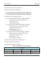
1.2.6 Released Databases
This release includes two sample unclassified databases:
The scenario named sdbv31 is a large, seven-sided, completely notional scenario database wherein
the forces are deployed on a fictitious island landmass and in the surrounding ocean. This example
scenario, developed and maintained for the Joint Warfighting Center (JWFC), is called Standard
Database Version 3.1.
JTLS 3.1.0.0
1-3
Version Description Document
JTLS Document 17
February 2006
The scenario blank31 is the sdbv31 database with all force structure data removed. It can be used as
the foundation to build your own database.
1.3 INTERFACE COMPATIBILITY
1.3.1 Support Software
JTLS 3.1.0.0 requires the following versions of support software, including operating systems,
compilers, scripting utilities, database tools, transfer protocols, and display managers.
a. Operating system for the model (one of the following):
1. Solaris 8 for use on Sun/SPARC Workstations
2. Solaris 9 for use on Sun/SPARC Workstations
3. Red Hat Linux Enterprise Edition Version 3.0 (ES)
4. Red Hat Linux Enterprise Edition Version 4.0 (ES)
b. Operating system for workstations (one of the following):
1. Solaris 8 for use on Sun/SPARC Workstations
2. Solaris 9 for use on Sun/SPARC Workstations
3. Red Hat Linux Enterprise Edition Version 3.0 (WS)
4. Red Hat Linux Enterprise Edition Version 4.0 (WS)
5. Windows 2000
6. Windows XP
Note: Although Solaris 8 and Solaris 9 are fully supported to operate JTLS
workstations, the Java-based Web-Hosted Interface Program
(WHIP) is noticeably more efficient on Linux-based or Windowsbased operating system machines.
c. Operating system for Support Software, such as HIP, SIP, etc:
1. Solaris 8 for use on Sun/SPARC Workstations (except for all HLA programs)
2. Solaris 9 for use on Sun/SPARC Workstations
3. Red Hat Linux Enterprise Edition Version 3.0 (ES)
4. Red Hat Linux Enterprise Edition Version 4.0 (ES)
d. Perl is used by the scripts that perform the DDS and PPS load/download functions. Perl is
delivered as part of the Solaris 8 OS, and is located in the /usr/bin directory. If Perl is installed
in a location other than /usr/bin, a link should be created from the /usr/bin directory to the Perl
program.
e. SIMSCRIPT II.5 Version 3.0.3 (SIMSCRIPT to C) translator/compiler: SIMSCRIPT is
required for recompiling JTLS code. It is not necessary to have a SIMSCRIPT compiler to
execute JTLS, because all JTLS software executables are statically linked with the
SIMSCRIPT libraries. The compiler is needed only if you are a U.S. Government
organization that can obtain source code and plan to re-compile JTLS SIMSCRIPT code. To
obtain a SIMSCRIPT compiler, contact CACI Inc.
Version Description Document
1-4
JTLS 3.1.0.0
February 2006
JTLS Document 17
f. ANSI C Compiler: It is not necessary to use a C compiler to execute JTLS. The compiler is
needed only if you are a U.S. Government organization that can obtain source code and plan
to re-compile any JTLS software program. If you need a C compiler, the following versions
will suffice:
1. SUN Solaris: ANSI C 5.2 or higher.
2. Linux - C Compiler as delivered with Red Hat Linux ES 3.0 or 4.0
g. C++ Compiler: It is not necessary to use a C++ compiler to execute JTLS. The compiler is
needed only if you are a U.S. Government organization that can obtain source code and plan
on re-compiling any of the JTLS HLA software programs. If you need a C++ compiler, the
following versions will suffice.
1. SUN Solaris: ANSI C++ 5.2 or higher
2. Linux - C++ Compiler as delivered with Red Hat Linux ES 3.0 or 4.0.
h. Windows software, X11R5 server, Motif 1.2 Library, Motif Window Manager. These items
are included as part of Solaris 8 or 9 and Linux ES 3.0 or 4.0
i. Adobe Acrobat Reader Version 4.0.5 or higher, is required to read the delivered JTLS
documentation. The JTLS 3.1.0.0 tar file (or CD) includes the freeware version of Acrobat
Reader.
j. JTLS database tools (DDS, PPS, GDP, SDR) requires the use of an Oracle database server and
the Oracle Form/Reports Developer 6i client/server runtime (with patchset 13 or higher).
Refer to Section 1.6.3, Oracle Compatibility and Installation of this chapter for additional
installation details.
k. TCP/IP is required for inter-process communication between the JODA data server and all
user interface programs. The version of TCP/IP included with Solaris 8 or 9, and Red Hat
Linux ES/WS 3.0 or 4.0 is sufficient.
l. Java Version 1.5 or higher is required for all platforms.
m. KDE Desktop support has been added to JTLS Version 3.1.0.0. Support of the GNOME
desktop is continuing, and use of the KDE environment is optional. Details regarding the
installation and use of KDE are provided in Section 4.4.3.2 of the JTLS Installation Manual.
1.3.2 HLA Compliance
The JTLS 3.1.0.0 release is fully High Level Architecture (HLA) compliant, and includes all the
programs required to run JTLS in an HLA mode on Solaris 8 or newer, or Redhat Linux ES 3.0 or
newer. The programs are the HLA Interface Program (HIP) and the PACER program. They are
executed only if the game is running in the HLA mode. The PACER is used during an HLA exercise
to control the advancement of federation time when the HIP “time management” option is enabled.
The HLA RTI (Run Time Infrastructure) executive program (rtiexec) recommended for use with this
release is RTI-NG-Pro-v3.0. However, this program is not included in the JTLS 3.1.0.0 delivery.
Users may obtain a full installation package of this RTI software from the vendor, Virtual Technology
Corporation, by contacting their web site at http://www.virtc.com. For information about executing
the HLA RTI Executive and other HLA-related software, refer to the appropriate HLA documentation
and user guides.
JTLS 3.1.0.0
1-5
Version Description Document
JTLS Document 17
February 2006
The HIP and PACER programs can be started by selecting their corresponding option buttons on the
ICPLogin Program. The HIP includes the capability to dynamically modify the lookahead time.
Lookahead time is an offset to future time from current time, and is the value used by each federate as
the earliest possible Time-Stamp-Ordered event it can generate. For information about procedures to
run the HIP and PACER programs using the ICPLogin Program, refer to the JTLS Technical
Coordinator’s Guide, Chapter 10.
1.3.3 Web Enabled Interface
The JTLS 3.1.0.0 release supports the WHIP and Web Enabled functionality only. The workstationbased Graphical Input Aggregate Control (GIAC) is no longer supported and cannot be used as a
Player or Controller interface for this version of JTLS.
1.4 INSTALLATION CONSIDERATIONS
The procedures for installing JTLS 3.1.0.0 depend on the hardware configuration at the installation
site. All installation considerations are addressed in the JTLS Installation Manual.
1.5 DATABASE MODIFICATIONS
This release includes the most current version of Standard Database (SDB), named sdbv31.
Significant database changes were made in conjunction with the upgrade from JTLS Version 3.0.0.0
to Version 3.1.0.0. These include the implementation of an interactive database modification process,
new data elements, and generic changes made to the previous Standard Database version The
following sections provide a detailed description of these changes.
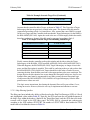
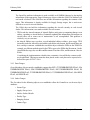
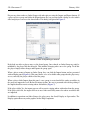
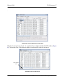
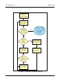
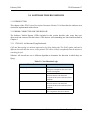
1.5.1 Interactive Database Upgrade
The JTLS Database Modify process has been enhanced to include an interactive feature that requires
user input while the upgrade process executes. This feature of the Database Development System
(DDS) process is accessed by a sequence of three JTLS Menu options: 1. Prepare or Alter a Scenario
Database > 1. Access the Database Development System Menu > 2. Access an Existing Database.
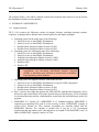
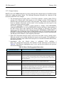
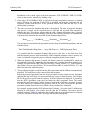
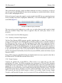
When the user selects and accesses a database that does not conform to the Standard Database 3.1
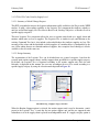
format, a Warning dialog box (Figure 1.1) queries the JTLS user to begin the upgrade process.
Version Description Document
1-6
JTLS 3.1.0.0
February 2006
JTLS Document 17
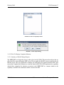
Figure 1.1 Starting the Database Upgrade
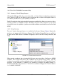
Selecting the Yes option executes a separate process, entitled Modifying Your JTLS Database, that
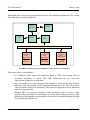
determines the existing format of the selected database, begins the upgrade, and displays its progress.
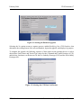
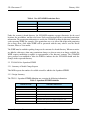
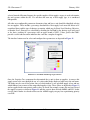
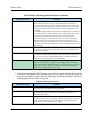
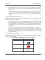
To complete the upgrade, the following sequence of three input screens prompts the user to select
desired base Unit Posture and Terrain Type values for the Command and Control Prototype (CCP),
and the base Lanchester coefficient sets for the Fire Lethality Prototype (FLP) and the Survivability
Prototype (SP).
Figure 1.2 Selecting the CCP Base Unit Posture
JTLS 3.1.0.0
1-7
Version Description Document
JTLS Document 17
February 2006
The Unit Posture entered for this prompt (Figure 1.2) becomes the base posture for new Command
and Control Prototype (CCP) base density values. The density values for the chosen posture will
become the base density values. The chosen posture is assigned a posture modifier of 1.0 and all other
posture modifiers will be computed according to their relationship with the selected posture. If your
database is a child of the Standard Database, you should choose the Defend posture.
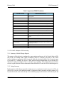
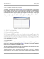
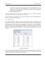
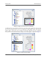
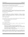
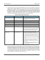
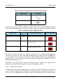
The Terrain Type entered for this prompt (Figure 1.3) will become the base terrain for new Command
and Control Prototype (CCP) base density values. The density values for the chosen terrain will
become the base density values. The chosen terrain is assigned a terrain modifier of 1.0 and all other
terrain modifiers will be computed according to their relationship with the selected terrain. If your
database is a child of the Standard Database, you should choose Open terrain.
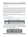
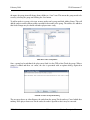
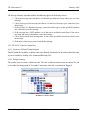
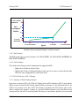
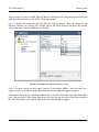
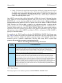
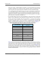
The Fire Lethality Prototype (FLP) and the Survivability Prototype (SP) entered for this prompt
(Figure 1.4) determine the Lanchester coefficient sets that will be retained. All FLPs are assigned an
FWL modifier to increase or decrease the relative lethality of the chosen coefficient sets. All SPs are
also assigned an FWL modifier to increase or decrease the relative vulnerability to the selected
coefficient sets. If your database is a child of the Standard Database, you should choose
BLOCK1_FLP and BLOCK1_SP.
Figure 1.3 Selecting the CCP Base Terrain Type
Version Description Document
1-8
JTLS 3.1.0.0
February 2006
JTLS Document 17
Figure 1.4 Selecting the FLP and SP Lanchester Sets
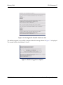
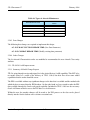
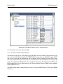
The database upgrade is successfully completed when the message shown in Figure 1.5 is displayed.
The terminal window should then be closed.
.
Figure 1.5 Database Upgrade Completed
JTLS 3.1.0.0
1-9
Version Description Document
JTLS Document 17
February 2006
Note: After the database is modified from Version 3.0 (or earlier) to Version 3.1
and downloaded to ASCII files, a successive scenario load is required to
properly create the check constraints in the database to include the new
illegal character set ( space " # & @ / { } < > ’ ). If any of your unit
names, target names, or other object names contain any of these
characters, they will be automatically removed from your database.
These symbols are incompatible with the JTLS 3.1.0.0 WHIP.
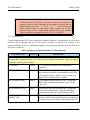
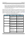
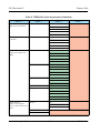
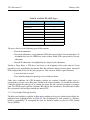
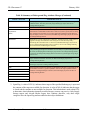
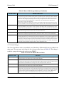
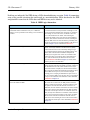
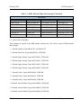
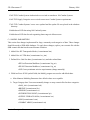
1.5.2 Data Elements
Currently implemented ECPs have required the addition, deletion, or modification of several data
elements. The description and use of the affected variables are presented in Chapter 2 and
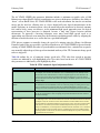
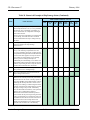
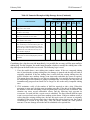
summarized below in Table 1. Detailed descriptions are provided in Appendix B of the JTLS Data
Requirements Manual.
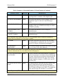
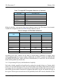
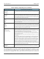
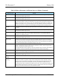
Table 1.Summary of Standard Database 3.1 Data Elements
VARIABLE NAME
CHANGE
DESCRIPTION
The new object IFF TRANSPONDER MODE (ITM) and the compound entity Air Control
Prototype/IFF Transponder Mode (ACP ITM) have been added to the database. These new objects
require the following new attributes.
ITM NAME
Added
The 15-character text name of the transponder
capability.
ITM CODE TYPE
Added
When an aircraft is assigned this Transponder Mode,
any air mission using the corresponding Aircraft Class
will output the Mode 1, Mode 2, Mode 3, Mode 4, or
Mode 5 codes indicated by this attribute.
AC ITM INDICATOR
Added
This attribute indicates whether the IFF Transponder
Mode (ITM) is onboard the member of the Aircraft
Class (AC).
ACP ITM INDICATOR
Added
This attribute indicates whether the IFF Transponder
Mode can be interpreted by a radar that belongs to a
Faction that uses this Air Control Prototype (ACP).
ACP ITM PROB
CORRECT ID
Added
This attribute indicates the probability that an air
mission with ITM onboard will be properly identified if
it is detected by a radar capable of interpreting this ITM.
Version Description Document
1-10
JTLS 3.1.0.0
February 2006
JTLS Document 17
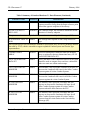
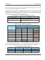
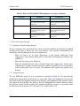
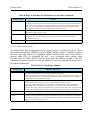
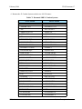
Table 1.Summary of Standard Database 3.1 Data Elements (Continued)
VARIABLE NAME
CHANGE
DESCRIPTION
These attributes were added to each Target Subcategory entity object, as appropriate, to indicate its
status as Underground or Open.
ST UNDERGROUND
FLAG
Added
This indicator is used to determine whether the Sensor
Type target is located underground.
SSA UNDERGROUND
FLAG
Added
This indicator is used to determine whether the Supply
Storage Area target is located underground.
SSM UNDERGROUND
FLAG
Added
This indicator is used to determine whether the SSM
launcher target is located underground.
FAT UNDERGROUND
FLAG
Added
This indicator is used to determine whether the Facility
target is located underground.
PS UNDERGROUND
FLAG
Added
This indicator is used to determine whether the Pumping
Station target is located underground.
JT UNDERGROUND
FLAG
Added
This indicator is used to determine whether the Jammer
Type target is located underground.
CC UNDERGROUND
FLAG
Added
This indicator is used to determine whether the
Communications Center target is located underground.
SSA OPEN FLAG
Added
This indicator is used to determine whether the Supply
Storage Area target is open and an overhead imagery
sensor can view its contents.
AS OPEN FLAG
Added
This indicator is used to determine whether the Aircraft
Shelter target is open and an overhead imagery sensor
can view its contents.
To improve the flexibility of the air mission speed specification and allow a user to manually
control the speed of an air mission during its flight profile, these attributes were added to the
Aircraft Class (AC) permanent entity.
AC STALL SPEED
Added
The slowest speed a member of this Aircraft Class can
safely fly.
AC STALL FUEL
MODIFIER
Added
This data parameter is a modifier for the amount of fuel
an air mission will consume per kilometers traveled
when the aircraft is flying at AC STALL SPEED.
JTLS 3.1.0.0
1-11
Version Description Document
JTLS Document 17
February 2006
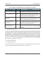
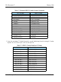
Table 1.Summary of Standard Database 3.1 Data Elements (Continued)
VARIABLE NAME
AC MAX FUEL
MODIFIER
CHANGE
Added
DESCRIPTION
This data parameter is a modifier for the amount of fuel
an air mission will consume per kilometers traveled
when the aircraft flies at AC MAX SPEED.
These Air Defense (AD) and Aircraft Class (AC) entity variables provide the specific USMTF
names by which all external USMTF programs and reports will refer to the objects defined by these
entities.
AD USMTF NAME
Added
This variable holds the United States Message Text
Format (USMTF) text name of the Air Defense object
type.
AC USMTF NAME
Modified
This variable holds the United States Message Text
Format (USMTF) text name of the Aircraft object type.
These Aircraft Class (AC) variables support enhancements to an aircraft malfunction maintenance
time algorithm that allows the average time for malfunction maintenance to be the same at both the
home base and at the detached squadron. The algorithm retains the current JTLS routine
maintenance computation as well as the status of preventive maintenance.
AC AVG
MALFUNCTION REPAIR
TIME
Added
The average time required to repair an aircraft that has
experienced a mechanical malfunction for which the
plane must be grounded and cannot fly until repaired.
AC AVG COMBAT
REPAIR TIME
Modified
The average time required to repair an aircraft that has
experienced combat damage for which the plane must
be grounded and cannot fly until repaired.
This database parameter was added to the Surface-to Surface Missile (SSM) prototype structure to
indicate whether an external model, such as MDST, will handle flight management. Based on this
parameter, an interface file can be prepared for MDST that lists all of the Targetable Weapons that
can be fired within JTLS and passed to MDST for flight.
SSM EXTERNAL
FLIGHT FLAG
Added
This flag indicates whether an external model,
presumably MDST, is responsible for the flight of the
missile from the time of launch to the time of impact.
These Ship Unit Prototype (SUP) attributes were added to support the representation of deploying
personnel onto lifeboats while a ship is sinking in a manner similar to the method used to represent
a downed JTLS aircrew.
Version Description Document
1-12
JTLS 3.1.0.0
February 2006
JTLS Document 17
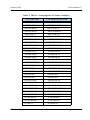
Table 1.Summary of Standard Database 3.1 Data Elements (Continued)
VARIABLE NAME
CHANGE
DESCRIPTION
SUP LIFEBOAT HUP
Added
When a ship that uses this SUP begins to sink, the HUP
specified by this data parameter is used to create
lifeboats for the ship’s personnel, personnel from
embarked squadrons, and personnel from carried units.
SUP LIFEBOAT MEAN
DEPLOY TIME
Added
When a ship that uses this SUP starts to sink, lifeboats
are created. A random process determines the time
interval between the deployments of individual
lifeboats. This deployment interval is selected from an
exponential distribution with a mean equal to the value
of this data parameter.
These attributes were added to the new Graphics Symbol (GS) permanent entity, which supports
the new DDS capability to process standard and customized object symbols (icons).
GS NAME
Added
This variable holds text name of the Graphics Symbol.
GS INDEX
Added
The variable holds the index of the Graphics Symbol.
This integer value is set for each object and used to
process object icons within the JODA data structure.
These attributes were added to the appropriate Target Class entities to define and display their
object symbols on the WHIP Map.
SLP CONVOY SYMBOL
Added
The symbol that should be used to display convoys that
are from Support Units that use this Sustainment
Logistics Prototype as specified in the Support Unit’s
Faction definition.
ATC TRACK SYMBOL
Added
The symbol that should be used to display a track or a
Cruise Missile that has been detected.
AD ICON SYMBOL
Added
The symbol that should be used to display a SAM/AAA
target that is a member of this Air Defense Class.
BC ICON SYMBOL
Added
The symbol that should be used to display a Bridge
target that is a member of this Bridge Class.
TUC ICON SYMBOL
Added
The symbol that should be used to display a Tunnel
target that is a member of this Tunnel Class.
ST ICON SYMBOL
Added
The symbol that should be used to display a Sensor
target that is a member of this Sensor Type.
JTLS 3.1.0.0
1-13
Version Description Document
JTLS Document 17
February 2006
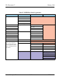
Table 1.Summary of Standard Database 3.1 Data Elements (Continued)
VARIABLE NAME
CHANGE
DESCRIPTION
RT ICON SYMBOL
Added
The symbol that should be used to display a Runway
target that is a member of this Runway Type.
IPT ICON SYMBOL
Added
The symbol that should be used to display an
Interdiction Point target that is a member of this
Interdiction Point Type.
SSA ICON SYMBOL
Added
The symbol that should be used to display a Supply
Storage target that is a member of this Supply Storage
Area.
SSM ICON SYMBOL
Added
The symbol that should be used to display a SSM target
that is a member of this Surface-to-Surface Missile.
FAT ICON SYMBOL
Added
The symbol that should be used to display a Facility
target that is a member of this Facility Type.
AST ICON SYMBOL
Added
The symbol that should be used to display an Aircraft
Shelter target that is a member of this Aircraft Shelter
Type.
MH ICON SYMBOL
Added
The symbol that should be used to display a MHE target
that is a member of this MHE Facility.
MFT ICON SYMBOL
Added
The symbol that should be used to display an MHE
target that is a member of this Minefield Type.
PS ICON SYMBOL
Added
The symbol that should be used to display a Pumping
Station target that is a member of this Pumping Station
Class.
JT ICON SYMBOL
Added
The symbol that should be used to display a Jammer
target that is a member of this Jammer Type.
CC ICON SYMBOL
Added
The symbol that should be used to display a Comm Site
target that is a member of this Communication Center.
CAT ICON SYMBOL
Added
The symbol that should be used to display a Combat
Arms target that is a member of this Combat Arms Type.
TC ICON SYMBOL
Added
The symbol that should be used to display a Vehicle
target that is a member of this Transportation Class.
SB ICON SYMBOL
Added
The symbol that should be used to display a Small Boat
target that is a member of this Small Boat Class.
Version Description Document
1-14
JTLS 3.1.0.0
February 2006
JTLS Document 17
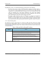
Table 1.Summary of Standard Database 3.1 Data Elements (Continued)
VARIABLE NAME
CHANGE
DESCRIPTION
SUT ICON SYMBOL
Added
The symbol that should be used to display a Supply
Type target that is a member of this Supply Type.
ACP MT ICON SYMBOL
Added
The symbol that should be used to display a Mission of
this Mission Type for each Air Control Prototype
(ACP).
ICON DMPI SYMBOL
Added
The symbol that should be used to display a DMPI,
regardless of the type of DMPI or the object to which
the DMPI is pointing.
ICON GENERAL UNIT
SYMBOL
Added
The symbol that should be used to display an
unidentified unit.
ICON GENERAL
TARGET SYMBOL
Added
The symbol that should be used to display an
unidentified target.
These attributes were added to the Unit Size (US) permanent entity to extend its capability to
support unit size indicators for JTLS object symbols.
US NAME
Added
The name associated with a specific Unit Size entity.
This name holds no significance, but is used to report
data to JTLS Players, and should be meaningful.
US MINIMUM
PERSONNEL
Added
The minimum number of personnel that can be in a unit
for it to use this UNIT SIZE definition.
These attributes were added to the appropriate Intelligence Information Prototype (IIP) compound
entities to determine the size of an object for detection purposes.
IIP TUT US DETECTION
MULTIPLIER
Added
A sensor’s baseline detection probability is multiplied
by this data parameter to determine the probability that
the sensor owned by an asset that uses the specified IIP
can detect a unit of Tactical Unit Type TUT (Airbase,
Ground, Squadron, Support, or FARP) with a specific
Unit Size (US).
IIP US SOF DETECTION
RATE
Added
This data parameter represents the rate at which a unit
from a Faction that uses the specified Intelligence
Information Prototype (IIP) and of the specified Unit
Size (US) detects foreign covert HRUs. The smaller the
value, the faster the unit will detect a covert HRU.
These Target entity (TG) attributes enhance the definition of Runway targets.
JTLS 3.1.0.0
1-15
Version Description Document
JTLS Document 17
February 2006
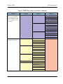
Table 1.Summary of Standard Database 3.1 Data Elements (Continued)
VARIABLE NAME
CHANGE
DESCRIPTION
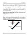
TG DIRECTION
Added
The value of this data parameter represents the direction
a person would be facing from the target reference point
toward the opposite endpoint of the runway.
TG DEC LAT and TG
DEC LONG
Modified
For a Runway target, this location is assumed to be the
location of a runway endpoint.
This parameter determines a typical sinking event duration for a Ship Unit Prototype (SUP).
SUP AVERAGE TIME TO
SINK
Added
The average time required to sink a ship of this SUP
type.
These parameters provide an alternative method to represent the force-on-force Lanchester attrition
data used by JTLS, which is intended to support expanded Combat System and Terrain Type
representations.
COMBAT INDEX
ARRAY
Deleted
This four-dimensional Lanchester Data Set identifier
array is replaced by the two-dimensional array UP UP
LANCHESTER DATA SET.
UP UP LANCHESTER
DATA SET
Added
This is the index of the Lanchester Data Set (FWL) that
should be used to compute force-on-force combat kills
when two units are within combat range.
CSP CS KILLER FWL
MODIFIER
Added
This attribute value represents a modifier to increase or
decrease the Lanchester kill rates for the killer Combat
System against all victim Combat Systems.
CSP CS VICTIM FWL
MODIFIER
Added
This attribute value represents a modifier to increase or
decrease the Lanchester kill rates for all killer Combat
Systems against the victim Combat System.
FLP FWL KILLER
MODIFIER
Added
The attribute value represents a modifier that will
increase or decrease the Lanchester kill rates for all
killer Combat Systems against all victim Combat
Systems when the killer unit uses the FLP.
SP FWL VICTIM
MODIFIER
Added
The attribute value represents a modifier that will
increase or decrease the Lanchester kill rates for all
killer Combat Systems against all victim Combat
System when the victim unit uses the Survivability
Prototype (SP).
Version Description Document
1-16
JTLS 3.1.0.0
February 2006
JTLS Document 17
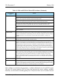
Table 1.Summary of Standard Database 3.1 Data Elements (Continued)
VARIABLE NAME
CHANGE
DESCRIPTION
CCP CS UP TT DENSITY
Deleted
This four-dimensional array is replaced by the following
Command Control Prototype (CCP) entity attributes.
CCP CS BASE DENSITY
Added
The baseline density with which a unit that uses the
specified CCP places its Combat Systems, regardless of
the unit’s current Terrain Type and Posture.
CCP CS TT DENSITY
MODIFER
Added
This data parameter is the multiplicative modifier that
should be applied to the base case density value when
the unit is located in the specified Terrain Type.
CCP CS UP DENSITY
MODIFIER
Added
The value held in this array is the multiplicative modifier
that should be applied to the base case density value
when the unit is in the specified Posture.
UT NIGHT
EFFECTIVENESS
Added
An attribute of the Unit entity, this multiplier is used in
Lanchester attrition calculations for combat during night
conditions.
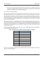
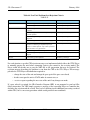
1.5.3 Standard Database Changes
The JTLS 3.1.0.0 Standard Database (SDB) includes extensive data item modifications implemented
since the SDB Version 3.0 release. If you have used sdbv30 has a basis for your existing scenarios,
you should review and evaluate the modifications included in sdbv31, the newest version of the
Standard Database. A significant enhancement included in sdbv31 is the addition of 57 new Combat
Systems, which enables the SDB to represent a total of 100 Combat Systems, which are described in
APPENDIX B. of this document. Reviewing your existing SDB-derived databases and upgrading
them to the new SDB format is strongly recommended. The detailed procedures required to upgrade
sdbv30 to sdbv31 are provided in APPENDIX C.
1.6 INSTALLATION NOTES
1.6.1 Installation Instructions
The JTLS Installation Manual (included in the documents compressed tar file that is part of this JTLS
release) provides detailed instructions for installing a new version of JTLS.
JTLS 3.1.0.0
1-17
Version Description Document
JTLS Document 17
February 2006
1.6.2 GIAC Compatibility
The Web Hosted Interface Program (WHIP) has replaced the GIAC in its entirety as the primary
JTLS Player and Controller graphical user interface. However, GIAC version 2.1.5+2 is provided as
part of this JTLS release to support the Graphical Database Program (GDP) capability. It is delivered
in the compressed tar files named GIAC.2.1.5.<platform_name>.tar.bz2. This version executes in
both Solaris and Linux environments.
1.6.3 Oracle Compatibility and Installation
This release of JTLS requires a complete installation of Oracle Forms/Reports Developer 6i client/
server runtime.
Developer 6i is the final version of the client/server development and deployment of Oracle Forms,
Reports, and Graphics. Oracle Corporation will provide only limited support for this Developer
version until January 2008, and Oracle10g will become the final certified database server compatible
with Developer 6i. Beginning with this release of JTLS 3.1.0.0, Oracle 10g iAS EE (Internet
Application Server Enterprise Edition) will be implemented to deploy JTLS database applications,
such as DDS Forms. The compatible database server version is Oracle 10g Standard Edition One or
newer. If these requirements are updated prior to a future JTLS release, they will be described in the
appropriate JTLS Version Description Document.
Utilizing the framework of iAS EE, which includes Forms Services, Reports Services, Portal, Single
Sign-On, Java, and other components, will enable the delivery of JTLS-specific data from a central
location. This will also allow the development of more scalable JTLS database applications, such as
the SDR and AAR.
Currently, the following combinations of Forms 6i runtime and the Oracle Server are approved for use
with JTLS:
a. Oracle database server 9.2.0.6, or 10g (Standard Edition One) for any platform
b. Forms 6i client/server runtime (with patch 13 or higher) for Solaris and/or Linux
c. iAS EE 10.1.2.0.2 full stack for Linux (optional)
Refer to Chapter 3, Section 3.6 of the JTLS Installation Manual for additional details regarding the
generic Solaris or Linux Oracle Forms/Reports Developer 6i client/server custom runtime
installation.
Version Description Document
1-18
JTLS 3.1.0.0
February 2006
JTLS Document 17
2.0 ENHANCEMENT CHANGE PROPOSALS
This chapter of the JTLS Version Description Document describes the model enhancement changes
implemented in JTLS Version 3.1.0.0. This version is a Major JTLS release that includes these
implemented Enhancement Change Proposals (ECPs).
2.1 JTLS-0028 Named Map Views
2.1.1 Summary of Model Change Request
This MCR requests the capability to save WHIP MAP configurations for later recall. The Map
component of the Web Hosted Interface Program (WHIP) provides a variety of configuration options
that permit the user to tailor the Map window to display simulation information of specific interest.
The configuration options include filters for Units, Terrain, OPAREAs, Networks, and National
Boundaries.
The Map component needs a capability to save the current location view and scale as well as the userselected filter configuration.
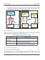
2.1.2 Design Summary
This design includes these proposed map display capabilities:
•
Saved views
•
Back/Forward views
•
Synchronized Authentication and Preferences (SYNAPSE) data-sharing enhancements
2.1.2.1 Saved Views
Users require the capability to save three types of information with respect to the current map display:
•
Location. Saved locations consist of the location center, current scale, and current
projection. Currently, the Map component has the capability to display Mercator, Lambert
Conformal, and Orthographic projections. The projection must be saved in conjunction with
the map location and scale to return the map view to a previous configuration. When a user
recalls a named and saved location setting, the location, scale, and projection of the map,
but not the filters, are altered.
•
Filters. Saved filters consist of all filter settings provided in the filter panel, including but not
limited to icon display filters, terrain filters, and icon size settings. If a map display
characteristic can be altered via the filter configuration panel, the current setting of the
characteristic are saved. When a user recalls a named and saved filter setting, all filters and
icon sizes are reset to the saved information, but the location of the map is not altered.
JTLS 3.1.0.0
2-1
Version Description Document
JTLS Document 17
•
February 2006
Views. A saved view consists of the union of the saved data for a saved location and a saved
filter. Thus, recalling a named and saved view will relocate the map to the saved location
and the reset the filters to the saved filter specification.
2.1.2.2 Back and Forward Scrolling
The Map requires a Back / Forward viewing feature to permit the user to return to a previous view.
This feature permits the user to sequentially traverse the recently viewed locations. Two mouseactivated controls, a back button and a forward button, have been added to the left Map control panel.
These buttons function in a manner similar to those of a Web browser. The back button sets the map
view to the previous location, scale and projection. The forward button sets the map view to the next
location, scale, and projection.
The information stored to accomplish this task consumes a minimal portion of memory resources.
The user’s previous 50 views are held, and the user can click the back button 50 times to display each
of these views. If the map location, scale, and projection is not changed, the forward button can also
be clicked to move forward in the view stack. If the user changes the location, scale, or projection, the
forward stack is cleared.
Consider the following example. Assume that a user opens a WHIP Map component and completes
the map adjustments listed in Table 2.
Table 2. Example Previous and Forward Map Component Capability
MAP VIEW
ADJUSTMENT
1
Open the Map component
2
Set the Project to Mercator
3
Zoom in
4
Zoom in
5
Scan up
6
Scan up
7
Scan up
8
Re-center on location X, Y
9
Re-center on a unit
10
Zoom out
Next, the user completes the following actions, listed in Table 3. The table indicates the map view
sequence that will be displayed.
Version Description Document
2-2
JTLS 3.1.0.0
February 2006
JTLS Document 17
Table 3. Use and Restriction of Forward and Back Button
USER ACTION
RESULTING MAP VIEW
Click back button
9
Click back button
8
Click back button
7
Click forward button
8
Click back button
7
Click back button
6
Zoom in on the display
This view replaces the previous map view 7
and the map views 8, 9, 10 are discarded.
2.1.2.3 SYNAPSE Modifications
The SYNAPSE Web service required design modifications to support saving locations, filters, and
views. In previous versions, the SYNAPSE provides three modes to the WHIP for storing
information. The WHIP could save data either privately for the named login (private data), shared to
the WHIP’s Side (Side-shared data), or shared to all WHIP users (world-shared data). This data
storage model is inadequate for managing saved data, since it is necessary that WHIP user has the
capability to specify multiple Sides permitted to access the data. Although not specifically required,
we decided to provide more flexibility by allowing the WHIP user to also limit access to saved data
according to specific WHIP names.
The new SYNAPSE data storage model implemented two storage types. Private storage is reserved
for data used only by a named WHIP, and Shared storage is used for data potentially available to be
shared among all WHIPs. These two storage areas are held in different directories under the
$JGAME/scenario_name directory.
•
Private storage functions as it did in previous versions of JTLS. Only the WHIP that owns
the private data is permitted to access it. Private data can never be shared.
•
Data intended or required to be shared must be placed in Shared storage to be accessible to
other WHIPs. This new Shared data area replaces the concepts of Side-shared data and
world-shared data. The named location, filter, and view files are all included in this Shared
storage area, even if the file can be viewed only by the owner or creator of the file. Each file
saved by a WHIP will require that permissions information be included to allow the
SYNAPSE to determine whether a specific WHIP is authorized to access the data. Table 4
describes this new permissions information.
JTLS 3.1.0.0
2-3
Version Description Document
JTLS Document 17
February 2006
Table 4. New SYNAPSE Permissions Data
NAME
DESCRIPTION
Owner
Name of the WHIP that saved the data
Side Read Permissions
List of Side names authorized to access the data
Player Read Permissions
List of WHIP names authorized to access the data
Under the scenario’s shared directory, the SYNAPSE maintains separate directories for the saved
locations, the saved filters, and the saved views. Each saved location will have associated permissions
information. The permissions information is used by the SYNAPSE to filter the directory contents for
each requesting WHIP. For example, if the permissions are set to allow Side Alpha read permission
for an entry, then a Side Alpha WHIP will be presented with the entry when it uses the Recall
Location, Filter, or View menus.
The WHIP must be notified regarding changes to the contents of a shared directory. When new entries
are added to a directory, when entry permissions change, or when an entry is no longer available, the
WHIP requires notification to update its representation of the directory contents. The SYNAPSE
query protocol was modified to allow the WHIP to indicate that the SYNAPSE should track the
changes in the requested directory.
2.2 JTLS-0050 New Squadron SITREP
2.2.1 Summary of Model Change Request
This MCR requests the number of available aircraft be added to the Squadron SITREP.
2.2.2 Design Summary
The JTLS 3.1 Squadron SITREP definition now contains the following information:
Table 5. Squadron SITREP Definition
VARIABLE NAME
VARIABLE DEFINITION
Name
Name of the unit
Object Class
Object Class of the unit
Location
Perceived location of the unit
Strength
Perceived strength of the unit
Homebase
The Short Name of the unit’s home base, if any
HHQ
The Short Name of this unit’s higher headquarters’ unit
AC Type
The name of the type of aircraft that this squadron owns
Version Description Document
2-4
JTLS 3.1.0.0
February 2006
JTLS Document 17
Table 5. Squadron SITREP Definition
VARIABLE NAME
VARIABLE DEFINITION
AC TOE
The number of aircraft authorized on the Table of Organization
and Equipment
AC Available
The number of aircraft currently available for us
Command Level
The level of the command assigned to the unit
Speed
The current speed of the unit
Destination
The last known location of the unit in latitude/longitude
Mission
The name of the unit’s ordered mission
Posture
The name of the current unit Posture
Side
The name of the Force Side to which the unit belongs
Faction
The name of the Faction to which the unit belongs
In Combat
Indicates if the unit is currently in combat
Support Unit
The name of the unit to support this squadron
Range
The maximum of the ranges of this units Direct/Indirect Fire
weapons
Maximum Speed
The unit’s maximum possible speed
Branch
The branch of the military to which the unit belongs
Max Sortie/cycle
The maximum number of sorties that the unit can sustain over a
prolonged period of time
AVN Fuel on Hand
The amount of fuel on available at this unit
Homebase AVN Fuel
The amount of fuel on available at the homebase
2.3 JTLS-0051 Multiple ACO Processing
2.3.1 Summary of Model Change Request
The purpose of this design is to enhance the representation and storage of Air Control Order (ACO)
data in the Air Tasking Order (ATO) Translation (ATO-T). Currently, processing a JTLS ATO
involves loading an appropriate ACO to properly define the mission locations. Due to operator error
or oversight, it is common for ACOs to omit mission location information for the current ATO.
Therefore, reading in multiple ACOs is a desirable user capability. This model enhancement allows
the user to gather mission location information from different ACOs into the ATO translation process.
2.3.2 Design Summary
Implementation of this design required a simple process to continuously read in successive ACOs. As
each ACO is read in, each mission location is compared to those currently stored in memory. If a
location that has the same name already exists within the program, that instance will be destroyed and
JTLS 3.1.0.0
2-5
Version Description Document
JTLS Document 17
February 2006
replaced with a new entry consisting of location information from the ACO currently being read. This
process continues until the user has read in all desired ACOs.
This process implies that the user must read in the ACOs from earliest to latest to ensure that the most
current location information is accessed.
2.4 JTLS-0082 Pass Aircraft Type Changes to Player GIACs
2.4.1 Summary of Model Change Request
If a controller changed the type of aircraft owned by a squadron, the GIAC did not have the capability
to alter its internal representation of the squadron. Thus many of the check made by the GIAC were
incorrectly being made based on the old vice the new squadron’s characteristics. The desire of this
ECP was to implement the WHIP so it could properly represent the adjusted squadron aircraft type.
2.4.2 Design Summary
When the Controller changes a squadron’s aircraft type, all programs including the JODA, WHIP, and
OMA are notified of the change. All internal representation of the squadron’s capabilities are properly
updated.
2.5 JTLS-0124 Change CEP Port Within ICP
2.5.1 Summary of Model change Request
This MCR requests the capability to change the service port number of the CEP.
2.5.2 Design Summary
The ICP now allows the user to edit the CEP port number. The default CEP port of 4244 is no longer
the mandatory port over which the CEP must communicate with the JODA. The port number is saved
to the .oex file of the scenario. When the CEP starts, it reads the specified port number from the .oex
file and uses it, rather than the default CEP port number.
2.6 JTLS-0150 IFF Improvement
2.6.1 Summary of Model Change Request
In previous versions, JTLS published a Mode 1, Mode 2, and Mode 3 squawk for all missions. This
information was published to real-world Command, Control, Communication, Computers, and
Information (C4I) systems, such as the Global Command Control System (GCCS), for reporting
purposes only. The representation of Identification Friend or Foe (IFF) was accomplished within
JTLS, but was unrelated to the existence or ability of the IFF hardware associated with the mission’s
aircraft.
Version Description Document
2-6
JTLS 3.1.0.0
February 2006
JTLS Document 17
The purpose of this Enhancement Change Proposal (ECP) is to more realistically represent the IFF
process within JTLS.
2.6.2 Design Summary
Currently, the Air Tasking Order (ATO) contains the Mode 1, Mode 2, and Mode 3 transponder codes
that the mission should use. This information is transmitted to JTLS by the ATO Translator (ATO-T)
and the data are published via the JTLS Object Distribution Authority (JODA) data server, and the
Joint Multi-Resolution Model (JMRM) High Level Architecture (HLA) feed. For non-ATO missions,
JTLS attempts to provide this information by accessing the squadron’s Mode 1 code and by
interpreting the mission name. If the assigned mission name is a legal IFF mode code (four-digit octal
number), this number is automatically assigned as the mission’s Mode 2 and Mode 3 code, or squawk.
If the mission name does not contain a legal code, the mission Mode 2 and Mode 3 squawks are
published as the general aviation Visual Flight Rule (VFR) reserved code of 1200.
JTLS now represents the IFF transponder equipment available on the aircraft, as well as the ability of
the detector to request and interpret the transponder-provided information. Each of these changes is
discussed separately.
2.6.2.1 Represent IFF Transponder Equipment
A new object called IFF TRANSPONDER MODE (ITM) has been added to the database, which has
the characteristics described in Table 6.
Table 6. IFF Transponder Mode Attribute Definitions
ATTRIBUTE
DESCRIPTION
ITM NAME
This is the 15-character name of the IFF transponder equipment.
ITM CODE TYPE
This is an enumerated type and can be set to MODE 1, MODE 2, MODE 2 CHANGEABLE,
MODE 3, MODE 3C, MODE 4, MODE 5, or UNNOWN OUTPUT. Table 13 describes the
rules established within the model for each of these enumerated types.
Table 7 contains sample data used throughout the remainder of this design discussion. These data are
completely hypothetical, but provide a framework for the user to understand the basic design
concepts. Note that several ITM objects are defined that have an ITM CODE TYPE of UNKNOWN
OUTPUT. These represent opposing force IFF capabilities for which IFF codes are not published, but
for which IFF identification probabilities would be held.
Table 7. Example IFF Transponder Mode Data
ITM NAME
JTLS 3.1.0.0
ITM CODE TYPE
IFF MODE 1
MODE 1
IFF MODE 2
MODE 2 CHANGEABLE
IFF MODE 2 OLD
MODE 2
2-7
Version Description Document
JTLS Document 17
February 2006
Table 7. Example IFF Transponder Mode Data (Continued)
ITM NAME
ITM CODE TYPE
IFF MODE 3
MODE 3
IFF MODE 3C
MODE 3C
IFF MODE 4
MODE 4
IFF MODE 5
MODE 5
OPFOR OLD
UNKNOWN OUTPUT
OPFOR CRYPT
NO OUPUT
Within the database, each Aircraft Class object indicates which of the ITM Modes it can transmit.
Consider the example data shown in Table 8 for three different aircraft.
Table 8. Example AC ITM INDICATOR Data
AIRCRAFT CLASS
ITM
F14
B2
MIG27
IFF MODE 1
YES
YES
NO
IFF MODE 2
NO
YES
NO
IFF MODE 2 OLD
YES
NO
NO
IFF MODE 3
YES
YES
YES
IFF MODE 3C
YES
YES
YES
IFF MODE 4
YES
YES
NO
IFF MODE 5
NO
YES
NO
OPFOR OLD
NO
NO
YES
OPFOR CRYPT
NO
NO
YES
According to these data, a MIG27 has the ability to transmit Mode 3 and Mode 3C altitude, which
will be published when the mission is flying. Additionally, the MIG27 transmits the OPFOR OLD
and OPFOR CRYPT modes, which will assist its identification by its own forces, but for which the
model will not publish any related code.
2.6.2.2 Representing IFF Query and Identification Capability
Each radar, whether ground based, naval based, or onboard an aircraft, belongs to a Faction, which
points to an Air Control Prototype (ACP). The ACP data indicate the IFF operation modes the Faction
can request. Once the radar detects an air mission, the model assumes that the radar requests its ACPallowed IFF operation modes. Based on the equipment onboard the aircraft, the mission will reply to
the requests. Each request answered increases the probability that the IFF correctly identifies the Side
Version Description Document
2-8
JTLS 3.1.0.0
February 2006
JTLS Document 17
that owns the aircraft. If the aircraft is correctly identified, the radar’s perception of the aircraft with
respect to owning Side and owning Faction is correctly set.
To implement this logic, another new compound entity similar to the Aircraft Class and IFF
Transponder Mode compound entity was added to the database. This new compound entity is the Air
Control Prototype and IFF Transponder Mode entity, which has two attributes described in Table 9.
Table 10 contains example data for this new compound entity.
Table 9. Summary of ACP ITM Compound Entity Attributes
ACP ITM ATTRIBUTE
MEANING
ACP ITM INDICATOR
This indicator determines that the Air Control Prototype (ACP) can
request the ITM when its detects an aircraft.
ACP ITM PROB CORRECT ID
This probability indicates whether a correct reply to the request will
result in a correct identification.
Table 10. Sample ACP ITM Compound Data
ACP
ITM
ACP_NATO
ACP_OPFOR
INDICATOR
PROBABILITY
INDICATOR
PROBABILITY
IFF MODE 1
YES
0.01
NO
IFF MODE 2
YES
0.01
NO
IFF MODE 2 OLD
YES
0.01
NO
IFF MODE 3
YES
0.02
YES
0.10
IFF MODE 3C
YES
0.05
YES
0.10
IFF MODE 4
YES
0.95
NO
IFF MODE 5
YES
1.0
NO
OPFOR OLD
NO
YES
0.05
OPFOR CRYPT
NO
YES
0.95
Assume a NATO radar (Side Alpha) detects a US (Side Charlie) F14 returning from escort duty as
part of a deep interdiction strike. Table 11 traces the calculation steps that are accomplished.
Table 11. Example of NATO Detecting F-14
MODE REQUEST
MODE REPLY
CUMULATIVE
PROBABILITY ID
IFF MODE 1
YES
YES
0.01
IFF MODE 2
YES
NO
0.01
MODE
JTLS 3.1.0.0
2-9
Version Description Document
JTLS Document 17
February 2006
Table 11. Example of NATO Detecting F-14 (Continued)
MODE REQUEST
MODE REPLY
CUMULATIVE
PROBABILITY ID
IFF MODE 2 OLD
YES
YES
0.0199
IFF MODE 3
YES
YES
0.039502
IFF MODE 3C
YES
YES
0.0875269
IFF MODE 4
YES
YES
0.954376345
IFF MODE 5
YES
NO
0.954376345
OPFOR OLD
NO
NO
0.954376345
OPFOR CRYPT
NO
NO
0.954376345
MODE
Following this computation, the model will draw a random variate to determine that the mission is
properly identified, which is highly likely. Next, consider the computation trace in Table 13, which
represents the OPFOR aircraft detecting the F14 during the deep interdiction strike.
Table 12. Example Of OPFOR Detecting F-14
MODE REQUEST
MODE REPLY
CUMULATIVE
PROBABILITY ID
IFF MODE 1
NO
NO
0.0
IFF MODE 2
NO
NO
0.0
IFF MODE 2 OLD
NO
NO
0.0
IFF MODE 3
YES
YES
0.1
IFF MODE 3C
YES
YES
0.19
IFF MODE 4
NO
NO
0.19
IFF MODE 5
NO
NO
0.19
OPFOR OLD
YES
NO
0.19
OPFOR CRYPT
YES
NO
0.19
MODE
Following this computation, the model will draw a random variate to determine whether the mission
is properly identified. Assume that a value of 0.65 is drawn. The model will not permit the OPFOR to
obtain a correct identification of this aircraft. Next, the model examines the IFF Friend or Foe state
change array that has existed in previous versions of JTLS. The correct identity of the air mission is
Side Charlie, and the probability that OPFOR will correctly “guess” this identity is 60%. The
probability that it will be labeled as a Side Delta air mission is 20%, and the probability that it will be
labeled as Unknown is 20%. If the mission is incorrectly identified, the IFF process is repeated when
the mission enters an adjacent hex. Once the mission is labeled correctly, the IFF procedure is
skipped.
Version Description Document
2-10
JTLS 3.1.0.0
February 2006
JTLS Document 17
Regarding these results, we recommend that database personnel observe the following:
•
As shown in the previous example, the IFF transponder equipment is primarily used by a
Side to determine whether it properly identifies its own aircraft. Because of this additional
computation, we recommend that database developers review their existing IFF Arrays and
reduce the probability that a Side properly identifies its own aircraft; this redundant
probability is determined after the detection fails the IFF computation. The result that
correct identification is 60% likely after this failure is unrealistic.
•
The database builder should note that if no ITM objects are present on an aircraft, its
probability of being correctly detected is zero, and the original IFF Array continues to
function as in previous JTLS versions. To quickly perform an update, the database builder
may consider only those IFF operation modes that will be reported to external C4I systems.
2.6.2.3 Mode Publishing Rules
The JODA data structure and the High Level Architecture (HLA) Run Time Infrastructure (RTI)
Federation Object Model (FOM) each have several air mission attributes used to represent the IFF
mode information transmitted by aircraft. These attributes and the rules that are used to evaluate them
are listed in Table 13.
Table 13. JODA and FOM Air Mission IFF Attributes
ENUMERATED
TYPE
MODE 1
RULES
This text attribute holds the two-digit code of the mission’s Mode 1 reply.
If the aircraft have an assigned ITM with an ITM CODE TYPE of MODE 1, the mission’s assigned
MODE 1 code us output to the JODA data structure and the HLA FOM.
If the mission order specified a Mode 1 IFF operation code, this code is passed to the JODA Mode 1
attribute for the output when the mission takes off and is cleared when the mission lands.
If the mission order did not include a Mode 1 IFF operation code, the operation code held by the
squadron is used.
If the squadron’s code is blank, a blank is passed to the JODA and the HLA FOM.
If the aircraft does not have an assigned ITM with an ITM CODE TYPE of MODE 1, the mission’s
MODE 1 code is left blank.
JTLS 3.1.0.0
2-11
Version Description Document
JTLS Document 17
February 2006
Table 13. JODA and FOM Air Mission IFF Attributes (Continued)
ENUMERATED
TYPE
MODE 2
RULES
This text attribute holds the four-digit code of the mission’s Mode 2 reply.
If the aircraft have an assigned ITM with an ITM CODE TYPE of MODE 2, the mission’s assigned
MODE 2 code is output to the JODA data structure and the HLA FOM.
If the mission order specified a Mode 2 IFF operation code, this code is passed to the JODA Mode 2
attribute for the output when the mission takes off and is cleared when the mission lands.
If the mission order did not include a Mode 2 IFF operation code, the model determines whether the
user-supplied mission name is a legal Mode 2 IFF code. If true, that Mode 2 IFF code is used.
If the mission name does not include a legal code, the code 1200 is passed to the JODA and the HLA
FOM.
If the aircraft does not have an assigned ITM with an ITM CODE TYPE of MODE 2, the MODE 2
attribute is left blank.
MODE 2
CHANGEABLE
The rules for this ITM CODE TYPE are the same as the enumerated type called MODE 2. The only
distinction between these ITMs is the user’s ability to alter the Mode 2 code published while the mission
is airborne. If the ITM has this enumerated type, the user is allowed to change the code via the Change
Air Mission Parameter order. If the ITM has an ITM CODE TYPE of MODE 2, a change is not
accepted.
MODE 3
The rules for this ITM CODE TYPE are the same as the enumerated type called MODE 2
CHANGEABLE except that the Mode 3 attribute is filled.
MODE 3C
The rules for this ITM CODE TYPE are the same as the enumerated type called MODE 2 except that
the Mode 3 attribute and the perceived altitude field for the JODA Air Mission object are filled. If
MODE 3C is not available as part of the detection, the perceived altitude will not be filled. Since filling
the altitude field now requires the existence of a MODE 3C capable transponder, we have provided a
new JODA attribute called “absolute altitude”. This attribute is not perceived data and will always be
available for display on the IMT by the Controller and the Side that owns the air mission. In this manner,
the JTLS player continues to have access to the mission’s current altitude, and the C4I systems attached
to JTLS are able to determine whether to show altitude for the contact.
MODE 4
The rules for this ITM CODE TYPE are different than the other modes discussed so far. The actual
output or code sent as a reply to a Mode 4 query is encrypted and highly classified. JTLS is not able to
output a realistic reply code for this equipment. Instead, JTLS simply sets the MODE 4 attribute to YES
(1), indicating that a proper encrypted and verified reply to a MODE 4 IFF query will be properly
answered. If the MODE 4 attribute is set to NO (0), the air mission is not MODE 4 capable. When a
Mode 4 capable air mission takes off, the MODE 4 characteristic is set to YES, then set to NO when the
mission lands.
MODE 5
The rules of this ITM CODE TYPE are the same as the rules and procedure described for MODE 4.
UNKNOWN OUTPUT
If the ITM CODE TYPE is set to UNKNOWN OUTPUT, then the equipment increases the probability
of correctly identifying your own aircraft as a friend, but no associated JODA attributes are filled, due to
the presence of the equipment onboard the air mission. This ITM CODE TYPE is designed to be used to
properly represent some unknown, presumably opposing force, IFF capability.
These attributes are useful for only one purpose—to display information on real-world C4I systems.
The only C4I systems linked to JTLS are those that represent the exercise audience capability.
Obviously, we do not link real-world opposing force C4I systems. In the cases of coalition exercises
Version Description Document
2-12
JTLS 3.1.0.0
February 2006
JTLS Document 17
to date, we believe that only one coalition partner has a C4I system linked to the game. For example,
we know of no situation in which US C4I systems and Japanese C4I systems are attached to the same
JTLS game. This is likely not true in the real world. During a coalition operation, the US, coalition
partners, and possibly the OPFOR will each have access to their separate real-world C4I system.
Thus, these IFF detections should realistically be considered perceived information. We have avoided
this definition, due to the modeling implications of sharing detections and sharing IFF information,
which are beyond the scope of this ECP. Thus, we define the IFF attributes shown in Table 13 as
common knowledge attributes. Detecting an air mission implies unlimited access to information held
in the common knowledge portion of the object data structure. By convention, we rely on the
interface programs to limit the access to this common knowledge information to realistic levels.
For example, Mission Type and Aircraft Type are two common knowledge air mission attributes. All
JTLS-delivered interface programs do not provide Mission Type information to a foreign Side upon
detection, but Aircraft Type is provided. We expect that the IFF common knowledge data is
judiciously provided to C4I systems in a similar and realistic manner. The US ability to query the
Mode 4 capability of an aircraft does not imply that Japan has the same capability; therefore, only
those interfaces that represent the US perception should access the Mode 4 common knowledge
attribute in the JODA and FOM. If Japan detects the mission, this information should not be made
available.
2.6.2.4 Rules for Turning Transponders On and Off
There are several reasons to justify a necessity to represent the ability to turn on and turn off the IFF
operation mode equipment represented by this design. Consider the following illustration:
1. As the design has been explained so far, having your transponder on will assist your own
Side to determine that you are a friendly mission, but there is no advantage to your enemy.
We are not aware of any disadvantage to keeping the transponder on in an encrypted IFF
operation mode. For non-encrypted IFF operation modes, especially MODE 3C, the
opposing force could obtain important information, especially your altitude. The problem is
that there are times when you would want the opposing force to know your altitude and
times when that would not be the desired circumstance. For example, consider the following
situations:
a. You are flying through an altitude-restricted no-fly zone area on a legal mission. The
Side enforcing the zone would need to know your altitude to ensure that the no-fly
constraints are observed. For this situation, you would want to transmit your altitude for
identification purposes. Currently, JTLS represents the enforcement of such no-fly
zones, but assumes that the enforcer can obtain altitude information for aircraft flying
through the area. How this altitude information is obtained is not considered.
b. You are an attack mission approaching a deep interdiction target. Any information
transmitted will facilitate the opposing force’s effort to intercept your mission and
realize your intentions prior to reaching the target. Currently, JTLS does not represent
altitude-related intercepting logic. Knowing the altitude of the intercepted track does not
affect an interceptor’s ability to conduct the intercept.
JTLS 3.1.0.0
2-13
Version Description Document
JTLS Document 17
February 2006
2. As we believe is correct, we assume that an encrypted IFF operation mode is an accurate
indicator of a friendly mission. We must represent malfunctioning IFF operation modes to
properly represent mis-identification within the exercise environment. The result of such a
malfunction would be that air defenses are required to follow different procedures to obtain
a confident assessment of the identification result. Currently, JTLS identification procedures
are not explicitly modeled. These procedures are assumed as part of the random process
represented by the IFF Probability Array.
Within the context of these examples, it is difficult to derive a reasonable and consistent set of rules to
automatically determine whether the IFF transponder equipment should be activated for a specific
situation. To represent some of these situations, we have provide the user an order capability to
manually turn on and turn off the equipment., However, we have maintain our current detection
assumptions in the majority of the JTLS air logic. If these are inappropriate, we recommend that
solutions be developed within other ECPs that address those assumptions explicitly. Table 14
summarizes the effect of each of these ITM CODE TYPEs within JTLS.
Table 14. Effect of ITM CODE TYPE Equipment Activation
ITM CODE
MODE 1
MODE 2
MODE 2 CHANGEABLE
MODE 3
MODE 3C
Version Description Document
TURNED ON
TURNED OFF
Mode 1 Code is transmitted.
Mode 1 Code is not transmitted.
Own Side is allowed to use its
associated probability of proper
identification.
Own Side is not allowed to use its
associated probability of proper
identification.
Mode 2 Code is transmitted.
Mode 2 Code is not transmitted.
Own Side is allowed to use its
associated probability of proper
identification.
Own Side is not allowed to use its
associated probability of proper
identification.
Mode 2 Code is transmitted.
Mode 2 Code is not transmitted.
Own Side is allowed to use its
associated probability of proper
identification.
Own Side is not allowed to use its
associated probability of proper
identification.
Mode 3 Code is transmitted.
Mode 3 Code is not transmitted.
Own Side is allowed to use its
associated probability of proper
identification.
Own Side is not allowed to use its
associated probability of proper
identification.
Mode 3 Code is transmitted.
Mode 3 Code is not transmitted.
Own Side is allowed to use its
associated probability of proper
identification.
Own Side is not allowed to use its
associated probability of proper
identification.
Altitude is transmitted. Aircraft
traveling through altitude-restricted nofly OPAREAs will cause an
interception only if the altitude
restrictions are violated.
Altitude is not transmitted. Such
aircraft will be identified as violating
altitude-restricted no-fly zones, causing
an interception. The track’s altitude will
be obtained upon visual identification.
Ability to intercept the mission is not
affected.
Ability to intercept the mission is not
affected.
2-14
JTLS 3.1.0.0
February 2006
JTLS Document 17
Table 14. Effect of ITM CODE TYPE Equipment Activation (Continued)
ITM CODE
MODE 4
MODE 5
UNKNOWN OUTPUT
TURNED ON
TURNED OFF
Mode 4 transmit flag is set to YES.
Mode 4 transmit flag is set to NO.
Own Side is allowed to use its
associated probability of proper
identification.
Own Side is not allowed to use its
associated probability of proper
identification.
Mode 5 transmit flag is set to YES.
Mode 5 transmit flag set to NO.
Own Side is allowed to use its
associated probability of proper
identification.
Own Side is not allowed to use its
associated probability of proper
identification.
Own Side is allowed to use its
associated probability of proper
identification.
Own Side is not allowed to use its
associated probability of proper
identification.
2.7 JTLS-0154 Target Filtering
2.7.1 Summary of Model Change Request
The user community has requested that the current static filter definition be dynamically modified
according to the types of objects that exist in the database. These specific recommendations for
dynamically generated filter panels have been implemented:
•
Filters for Targets are by Target Subcategory so that specific SAM/AAA Target
subcategories, such as Patriot, Hawk, ZSU-23, and others can be displayed or hidden by the
WHIP user.
•
Filters for Naval units are by Ship Class.
•
Filters for ground-based units, such as Ground Combat units, Support units, Airbase units,
and others are by graphics symbol for the object and these symbols have been categorized to
make the filter panel easier to traverse. The definition of the graphics icon groups is user
defined.
2.7.2 Design Summary
The new WHIP filter panel has been reorganized as described in Table 15. The major filtering
modifications implemented for this design are color-coded. Table cells highlighted green describe
filter panel features that support the desired Target filtering, cells highlighted yellow describe features
that support the desired Ship Class filtering, and cells highlighted blue describe filtering features
based on unit symbols. Details regarding these implemented filtering categories are presented within
the following sections: Section 2.7.2.1, Section 2.7.2.2, and Section 2.7.2.3.
JTLS 3.1.0.0
2-15
Version Description Document
JTLS Document 17
February 2006
Table 15. WHIP Filter Panel Organization
LEVEL 1
Object Type
LEVEL 2
LEVEL 3
LEVEL 4
Ground
Support
Airbase
...
Unidentified Target
General Characteristics
Strength
75% - 100%
50% - 74%
25% - 49%
0% - 24%
Unit Posture
Attack
Defend
Delay
...
Wiped Out
HLA Controlled
Land Units
Applies only to land-based
units, Ground Combat Units,
Airbases, Squadrons, FARPs,
Support, and High Resolution
Units (HRUs).
In Combat
Command Level
Squad
Section
Platoon
...
Army Group
Unit Symbol
Command
HQ_AIR_DEFENSE
JOINT_TF_HQ
HEADQUARTERS
...
HQ_CORPS
Version Description Document
2-16
JTLS 3.1.0.0
February 2006
JTLS Document 17
Table 15. WHIP Filter Panel Organization (Continued)
LEVEL 1
Land Units
Applies only to land-based
units, Ground Combat Units,
Airbases, Squadrons, FARPs,
Support, and High Resolution
Units (HRUs).
LEVEL 2
Unit Symbol
LEVEL 3
Combat
LEVEL 4
INFANTRY
INFANTRY_BIFB
INF_LIGHT
...
INF_MOTORIZE
Combat Service Support
ENGINEER
BRIDGING
CHEM_DECON
...
CHEMICAL
Support
FRWD_AREA_SUP_CTR
MEDICAL
TRANSPORTATION
LOGISTICS
Naval
Applies only to Naval units.
CARRIER
NIMITZ_US
KITTY.HAWK_US
CH.DEGAULLE_FR
KUZNETSOV_RS
COMBATANT
AVENGER_US
NANUCHKA.3_RS
NATYA.II_RS
...
OSA.II_IR
SUPPLY SHIP
CARGO_SHIP_GEN
CHILIKIN.B_RS
MERCHANT_GEN
TANKERSHIP_GEN
...
SUBMARINE
AKULA_2_RS
L.ANGELES_NV_US
L.ANGELES_LV_US
...
OSCAR_2_RS
JTLS 3.1.0.0
2-17
Version Description Document
JTLS Document 17
February 2006
Table 15. WHIP Filter Panel Organization (Continued)
LEVEL 1
Air Missions
Applies only to air missions.
LEVEL 2
Air Mission Type
LEVEL 3
LEVEL 4
Airlift
Transport
AWACS
...
Strategic Lift
Air Mission
(Continued)
Mission Posture
Flying
Orbiting
Attacking
...
Combat Delay
Targets/DMPIs
Applies only to Targets and
DMPIs.
SAM/AAA
AAA.GUN
SAM1
STINGER
...
ZSU23-4
Bridge
LRG.RAILBRDG
LRG.ROADBEDG
PONTOON.BRDG
...
SML.ROADBRDG
Tunnel
LRG_TUNNEL
MED_TUNNEL
SML_TUNNEL
...
Supply Type
AA_MSL
ART_TNK
CL.IV
...
WATER_BULK
Graphical Objects
Applies only to graphical
objects, as shown in the Level 2
entries.
Networks
Rail
Pipeline
IADS
OP Area
National Boundary
Version Description Document
2-18
JTLS 3.1.0.0
February 2006
JTLS Document 17
Some additional refinements are also a part of this reorganization:
•
Since unit Posture applies to all land-based and naval units, this filter category was
subsumed within a new General Characteristics filter item in conjunction with Strength. The
HLA Controlled filter, which applies to several different object types, such as Land-based
units, Naval units, Targets, and Air Missions; is also appropriately included within the
General Characteristics Level 1 category. The remaining Level 1 categories can now be
viewed as specific object type filters. The applicable object types are indicated under the
description of the meaning of the Level 1 filter category.
•
The graphics objects, such as Networks, OPAREAs, and National Boundaries were
combined within a Graphics Object Level 1 category to reduce the number of Level 1
categories and create a more compact and usable filter panel.The current Map Component
filter configuration file will be separated into two files; a static filter configuration file
($JGAME/data/mapfilters-conf.xml) and a dynamic filter configuration file ($JGAME/
<scenario>/webroot/mapfilters-dynamic.xml). The dynamic filter file must be generated
according to the contents of the scenario that is being run. For example, if there are no
Targets of type category SAM/AAA and Subcategory of SAM1, the corresponding filter
option should not appear in the filter panel. This allows the filter panel to be adaptable to the
specific scenario without becoming overburdened with options that do not exist in the
scenario.
The dynamic filter file is automatically generated as part of the scenario setup function for the
Scenario Initialization Program. Additionally, the dynamic filter file is regenerated if the existing filter
panel is no longer complete due to Player or Controller action.
The static Map filter configuration file contains the filter configurations for all filters except those that
are dynamic. The static filter file contains placeholders or indicators to designate placement of the
dynamic filter configuration data. When the WHIP reads the mapfilters-conf.xml and the mapfiltersdynamic.xml files, the WHIP splices the dynamic filters into these placeholders and then creates the
filter panel for the map component.
The user interface behavior for the Map Component filters has not change with the implementation of
this design. The user will still manipulate the filter setting in the same manner. At each Level, the
WHIP user has two options:
•
Change the filter setting for all options under the level. This is a global level filter alteration.
•
Open up the level to reveal the sub-level and change any one or multiple options within the
newly revealed sub-level. This is a specific filter alteration.
The only modification to the filter interface a WHIP user will notice is the additional options and
levels of filter detail that can be changed.
JTLS 3.1.0.0
2-19
Version Description Document
JTLS Document 17
February 2006
2.7.2.1 Target Filtering Specifics
The filter panel includes the Target subcategories, highlighted green within Table 15. The user is able
to turn on, turn off, highlight, or blink all Targets of a specific category, as is currently allowed.
Additionally, the user is able to alter the same characteristics according to the Target’s Subcategory.
This means the following situations can be represented for SAM/AAA Targets:
•
Display all SAM/AAA Targets and blink the SA-10s
•
Hide all SAM/AAA Targets, except SA-7s, SA-6s, and SA-10s
•
Show all SAM/AAA Targets, except AAA.GUNS
The same flexibility applies to all Target categories.
The listed Level 2 Target categories are part of the fixed map filters data file and will always appear.
These are based on the 21 different Target categories represented within JTLS. The filter panel lists
only those Target subcategories for which at least one Target or one Desired Mean Point of Impact
(DMPI) exists in the scenario. If no ALBATROS(3).L SAM/AAA Targets or DMPIs exist in the
database, this Subcategory will not appear on the Level 3 filter panel. To maintain a correct filter
representation, Technical Control should run the JTLS Setup procedure each time a new database is
used to run a scenario.
As the game executes, it is possible for the Controller to create new Targets or new DMPIs; therefore,
it would be possible for the scenario to actually contain an ALBATROS(3).L SAM/AAA Target and
this type of SAM/AAA Target would not appear on the filter panel. For this reason, the CEP must
determine whether a new filter panel must be created and regenerate the dynamic filter file as
appropriate. The following Target and DMPI situations represent rules that trigger the model to
generate a new filter file:
1. A new Target is created and no other Target or DMPI exists in the scenario with the
specified Target Subcategory.
2. A new DMPI is created and no other Target or DMPI exists in the scenario with the
specified Target Subcategory.
3. The Controller changes the Subcategory of an existing Target and no other Target or DMPI
exists in the scenario with the specified Target Subcategory. Note that when the Controller
changes the Subcategory of an existing Target, it is possible that a Subcategory on the
current filter panel no longer exists. Consider the following example. Assume that the
scenario has only four SAM/AAA Targets, as listed in Table 16.
Table 16. Example Scenario Target List
SCENARIO SAM/AAA TARGET
TG SUBCATGORY
UNITA_GUN
AAA.GUN
SHIP2_PROT
SAM1
HRU_TEAM1_STNGR
STINGER
Version Description Document
2-20
JTLS 3.1.0.0
February 2006
JTLS Document 17
Table 16. Example Scenario Target List (Continued)
SCENARIO SAM/AAA TARGET
BAD_ZSU
TG SUBCATGORY
ZSU23-4
Assume that the controller adds a Target, as shown in Table 17. This Target has a Target
Subcategory that has not previously existed in the game. The dynamic filter file must be
regenerated according to Rule 1 as stated above. Also, assume that a new DMPI is created
for this new Target and the Controller indicates that the Target Subcategory for the DMPI is
the ROLANDS3(SP+VAN). Again, the result is the use of a Subcategory within the model;
therefore, another new dynamic filter file must be generated according to Rule 2.
Table 17. Example Scenario Target List Including Added Target
SCENARIO SAM/AAA TARGET
TG SUBCATGORY
UNITA_GUN
AAA.GUN
SHIP2_PROT
SAM1
HRU_TEAM1_STNGR
STINGER
BAD_ZSU
ZSU23-4
RANDA_SITE
ROLAND2(SP+VAN)
Finally, assume that the controller realizes this mistake and decides to alter the Target
Subcategory of the RANDA_SITE from ROLAND2(SP+VAN) to ROLAND3(SP+VAN).
When this happens, the ROLAND2(SP+VAN) Target Subcategory no longer exists in the
game, and the filter option is unusable. This could be confusing to the user who realizes that
no ROLAND2(SP+VAN) SAM/AAA Targets should be in the order of battle. However,
removing the item from the filter panel once it has appeared may also cause confusion. The
design decision for this situation was to not change the filter panel in this case, but if a new
dynamic filter panel must be regenerated for any other reason, the new filter panel logic
would remove the ROLAND2(SP+VAN) SAM/AAA Target Subcategory from the filter
panel because it does not exist.
This logic seems inconsistent, but altering the dynamic filters will occur seldom, if ever,
during an exercise. However, this rule was easy to implement and efficient to execute.
2.7.2.2 Ship Filtering Specifics
The filter panel now includes the ability to filter based on the Ship Unit Prototype (SUP) of a Naval
unit, highlighted yellow within Table 15. Typically, the SUP represents the real-world designator of
the ship’s class within the database. Similar to the Target filter panel, only the SUPs that exist in the
scenario will be listed in the SUP filter panel. The SUPs will be separated into subcategories
according to the SUP attribute SUP TYPE. The number of SUP TYPEs is fixed within the JTLS
model and each is defined as shown in Table 18.
JTLS 3.1.0.0
2-21
Version Description Document
JTLS Document 17
February 2006
Table 18. Available JTLS SUP Types
SUP TYPE NAME
NUMERIC IDENTIFIER
CARRIER
1
COMBATANT
2
SUPPLY SHIP
3
AMPHIB
4
HELO CAPABLE
5
SUPPLY HELO CAPABLE
6
AMPHIB HELO CAPABLE
7
SUBMARINE
8
The user is able to set the following types of filter options:
•
Turn on all submarines.
•
Turn on all submarines, except submarine SUPs that represent diesel electric submarines. To
accomplish this task, the WHIP user needs to know which SUPs represent diesel electric
submarines.
•
Turn off all submarines, but highlight the Los Angeles class submarines.
Similar to Target filters, a SUP that is not in use at the beginning of the game when the Setup
procedure creates and publishes the dynamic filter file will not be displayed on the panel. An unused
SUP could possibly be used as the game progresses. This can occur in these typical situations:
•
A new naval unit is created.
•
The Controller changes the prototype of an existing naval unit.
Under these conditions, the CEP determines whether the resulting Controller action creates a
requirement to generate a new filter panel. Similar to the Target situations, it is feasible that when the
Controller changes the prototype of an existing naval unit, the unit’s previous prototype is no longer
used. The CEP does not regenerate a dynamic filter file for this circumstance, but when and if a filter
file is generated it will no longer include the unused SUP.
2.7.2.3 Unit Symbol Filtering Specifics
The filter panel includes a capability to filter units according to the type of symbol used to display the
land-based unit, highlighted blue in Table 15. The development of such symbols is a database
builder’s responsibility. To accomplish this task, the database builder accesses the JTLS Symbol
Server (JSYMS).
Version Description Document
2-22
JTLS 3.1.0.0
February 2006
JTLS Document 17
In addition to building these symbols, the database developer is also responsible for categorizing
them. The primary purpose of this categorization is to make the Map filter capability more useful.
Currently, JTLS utilizes more than 100 symbols, many of which do not apply to land-based units.
Therefore, there was a need to specify which symbols should be classified in the Level 3 filter for land
units.
The JTLS 3.1.0.0 delivery includes a default symbol categorization scheme. Users who choose to
modify the selected categories are fully capable of creating their own category scheme, which will
automatically be applied to the Map filter panel via the dynamic filter file. Each scenario can have its
own categorization scheme as desired. When a new scenario is created, the default scheme is used for
the scenario, but the database builder can alter the new scenario’s scheme specifically for that
scenario, or generally for all of a organization’s existing scenarios.
The Scenario Verification Program (SVP) checks for consistency and ensure that the symbol assigned
for each land unit, i.e. Ground Combat Unit, Airbase, Squadron, FARP, Support Unit, or HRU, has
been assigned a category. If the symbol is not included in a category, a Warning is generated to
indicate that control of the object by means of its symbol cannot be accomplished.
2.7.2.4 WHIP Filter File Notification
Another delivered ECP entitled JTLS-0028 Named Map Views defines a requirement for saving and
recalling map filter settings, as well as locations and views (combinations of a location and filter
settings). This design considers the dynamic nature of some of the filter configuration data and saves
the dynamic filter settings concurrently with the static filter settings when the user performs a save of
filters.
Because part of the map filter configuration is dynamic, a problem potentially exists if the saved
filters do not match the current dynamic filter configuration file as it was most recently written by the
SIP or the CEP. This problem is avoided by first loading the default filter settings prior to each recall
of save filters. This ensures that any new Target Subcategory filters are set to the default settings and
will not have an undetermined value after the save filters are recalled. If a Target Subcategory filter is
no longer in the dynamic filters, a possible but rare occurrence, the filter will be ignored by the filter
loading algorithm.
2.7.3 Data Changes
No Database Development System (DDS) data changes are required to support this ECP. Minor
modifications were made to the data file generated by the JTLS Symbol Server (JSYMS) that is used
by the DDS.
JTLS 3.1.0.0
2-23
Version Description Document
JTLS Document 17
February 2006
2.8 JTLS-0277 Target Underground Flag
2.8.1 Summary of Model Change Request
Within JTLS, military units, ships, small teams of personnel (High Resolution Units), air missions,
and convoys are modeled or represented as physical objects. The model also represents an additional
physical object referred to as a target. A JTLS target is defined as a militarily significant object not
included in any other physical object category. Unfortunately, the term target can confuse uninitiated
model users because all JTLS physical objects can be targeted. For example, a Player has the ability
to attack a specific military unit, such as an airbase or support depot. Ships can be attacked by various
means, including ship-to-ship gunfire or torpedoes. High Resolution Units (HRUs) can engage in
combat with each other and be killed by aggregate-level military units with which they come in
contact. The same is true for air missions and convoys. As their names suggest, targets can also be
targeted or attacked within JTLS.
The detection of targets in JTLS is currently determined by using the Target Category and
Subcategory multiplier held in the IIP TGC PROB DETECTION MULT ARRAY to adjust the
baseline PD of the sensor that attempts the detection. For a Target Subcategory that represents an
underground facility, the database is built in such a manner that value of the Target Subcategory
detection multiplier is very small. Thus, detecting and reporting the status of these targets in JTLS is
difficult.
This method has worked well for JTLS in the past, but within the Joint Multi-Resolution Model
(JMRM) other intelligence collection models such as Tactical Simulation (TACSIM) and Multiple
Unified Simulated Environment / Air Force Synthetic Environment for Reconnaissance and
Surveillance (MUSE/AFSERS) are linked to JTLS. For TACSIM and MUSE/AFSERS to properly
interpret an underground target, a specific attribute must be attached to the object within the FOM.
The JTLS representation of an underground target based on the PD is subject to undesirable
interpretation. For this reason, adding a dedicated attribute that indicates whether the target is
underground is desirable.
In addition there was a desire to add an attribute indicating whether an imagery collection sensor can
“see” or obtain information regarding the contents of the target. An illustrative example of this
concept is the Aircraft Shelter target, which can contain aircraft. Some Aircraft Shelter targets
represent concrete hangars and others can represent outdoor revetments which protect aircraft from
adjacent bomb damage. An overhead imagery sensor may or may not be able to determine whether
the Aircraft Shelter contains any aircraft, but it would be easy for the sensor to obtain information
regarding the aircraft held within a revetment.
2.8.2 Design Summary
Like many JTLS designs, this simple improvement concept can create opportunities for additional
improvements and expand the scope of the associated ECP. Due to time constraints, we have refrained
Version Description Document
2-24
JTLS 3.1.0.0
February 2006
JTLS Document 17
from expanding this capability, but have included several suggestions that the Government can
consider as future ECPs.
The implemented improvement is simple. We added two new attributes to each Target Subcategory
object for which the attributes are appropriate:
1. Underground Flag. A value of YES (1) indicates that a target of the specified subcategory is
underground. A value of NO (0) indicated an above-ground target. This flag is not used within
JTLS to determine whether a target is available for detection. JTLS continues to use the IIP
TGC PROB DETECTION MULT ARRAY to determine the probability that an imagery
sensor can collect information regarding the status of the target. This approach was selected
because this probability can implicitly represent many non-modeled concepts. For example,
although a Supply Storage target may be underground, it is possible that imagery sensors
detect activity near the target, which indicates the location of an actively used Supply Storage
area. Continuing to represent this type of situation by means of the PD is desirable.
The Underground Flag is used to alter the manner of indicating the status of an underground
facility within JTLS intelligence reports, and also is used to update the JMRM FOM attribute
to indicate to other federates that the facility is underground and to apply their unique logic for
this situation. Table 19 summarizes the Target Categories for which we added either an
Underground Flag, an Open Flag, or both. The reasons for each decision are described and
color-coded. Red cells indicate neither flag was added to the Target Category. Green cells
indicate that the labeled flag was added for the Target Category. A cell highlighted yellow
indicates a unique condition that was specifically considered.
Table 19. Summary of Underground Flag Attribute Changes
TARGET CATEGORY
UNDERGROUND FLAG
SAM/AAA
SAM/AAA sites do not have an Underground Flag attribute
BRIDGE
Bridges do not have an Underground Flag attribute.
TUNNEL
All tunnels are underground, but a reasonable assumption is that the entrances to the tunnels
are above ground and visible to imagery intelligence collection assets. Therefore, tunnels do
not have an Underground Flag attribute.
SENSOR SITE
Since sensor sites represent sonars as well as air search radars, Sensor Site Target
Subcategory objects do have an Underground Flag attribute. For shipboard sensors, the
Underground Flag indicates that the sensor is not top-side and the sensor’s current
functionality status cannot be determined through imagery data collection.
RUNWAY
Runways do not have an Underground Flag attribute.
INTERDICTION POINT
Interdiction point targets do not have an Underground Flag attribute.
SUPPLY STORAGE
Supply Storage targets can be underground; therefore, the Supply Storage Area Target
Subcategory object does have an Underground Flag attribute.
SSM
SSM targets can represent torpedoes as well as cruise missile launchers and TBM launchers.
Therefore, the SSM Target Subcategory objects does have an Underground Flag attribute for
the same reasons described for Sensor Sites.
JTLS 3.1.0.0
2-25
Version Description Document
JTLS Document 17
February 2006
Table 19. Summary of Underground Flag Attribute Changes (Continued)
TARGET CATEGORY
UNDERGROUND FLAG
FACILITY
Facility targets can represent a wide variety of underground facilities, such as underground
command centers. Therefore, the Facility Target Subcategory objects does have an
Underground Flag attribute.
AIRCRAFT SHELTER
Aircraft Shelters do not have an Underground Flag attribute.
MATERIEL HANDLING
EQUIPMENT
(MHE)
MHE is currently used within JTLS to load ships, aircraft, and convoys. Although we can
find situations in which MHE would be able to load convoys below ground, there are many
other problems associated with convoys being loaded and unloaded beyond the detection
range of imagery sensors. For this reason, the MHE Target Subcategory objects do not have
an Underground Flag attribute.
MINEFIELD
Minefields are typically underground or underwater; assuming otherwise would require an
upgrade to the logic associated with a unit moving into an area and unexpectedly
determining that a minefield exists. For this reason, Minefield Subcategory objects do not
have an Underground Flag attribute, but for consistency we do set the Underground Flag
that is held for each minefield target in the FOM.
PUMPING STATION
Since Supply Storage targets can be represented underground, Pumping Stations used to fill
underground supply storage areas should also have the ability to be placed underground. For
this reason, the Pumping Station Subcategory object do have an Underground Flag attribute.
It is legal for an underground pumping station to fill an above-ground supply storage target
and vice versa.
JAMMER
Jammers are similar to sensors, and consistency between these two Target Subcategory
objects should be maintained. Therefore, the Jammer Subcategory object has an
Underground Flag attribute.
COMM SITE
Some communication centers are underground; therefore, the Communication Site
Subcategory object has an Underground Flag attribute.
SHIP
These target sub-categories are used only as placeholders for PD data or occasionally for the
representation of some very specific capabilities. None of the target capabilities indicate
usefulness as underground targets. Therefore, these Subcategory objects do not have an
Underground Flag attribute.
COMBAT ARMS
VEHICLES
AIRCRAFT
SMALL BOAT
SUPPLY TYPE
2. Open Flag. A value of YES (1) indicates that a target of the specified Subcategory is open and
the contents of the target are available for detection. A value of NO (0) indicates that the target
is closed and the contents are not available for detection. This information is used within JTLS
to determine what information internally modeled imagery sensors can perceive. Only Supply
Storage targets and Aircraft Shelter targets have contents; therefore, only these target
categories have the Open Flag attribute added to their object definitions.
Version Description Document
2-26
JTLS 3.1.0.0
February 2006
JTLS Document 17
The Open Flag attribute information is made available to all JMRM federates by placing this
information on the appropriate Target Subcategory objects within the FOM. This attribute will
not benefit a federate if the FOM does not include information regarding the contents of the
target. This information is already available for Supply Storage targets, but is much more
difficult to access for Aircraft Shelters.
The JODA does not hold the information regarding the aircraft currently in each aircraft
shelter. This information is not made available for two reasons:
•
JTLS tracks the aircraft contents of Aircraft Shelters only prior to computing damage to an
airbase, squadron, or aircraft shelter. Continually updating this information each instance an
aircraft takes off or comes out of maintenance is not accomplished. This problem is
relatively easy to overcome.
•
An Aircraft Shelter target can have several individual shelters within a given target. JTLS
internally tracks the aircraft located within each shelter sub-element, but the model does not
have an object structure established to track this object within the JODA or the FOM. For
example, no efficient method exists for the CEP to pass to the JODA that Revetment 1 in the
Aircraft Shelter target has two B2s and Revetment 2 has three B2s, and Revetment 3 has six
FA18s.
Considering the implementation schedule time constraints, Aircraft Shelter contents could
not be published. This improvement has been placed on the work plan and is expected to be
delivered as part of JTLS 3.2.0.0.
2.8.3 Data Changes
Several database objects must be modified to support this ECP: ST UNDERGROUND FLAG, SSA
UNDERGROUND FLAG, SSM UNDERGROUND FLAG, FAT UNDERGROUND FLAG, PS
UNDERGROUND FLAG, JT UNDERGROUND FLAG, CC UNDERGROUND FLAG, SSA OPEN
FLAG, AS OPEN FLAG
2.8.4 Order Changes
The Set orders for the following objects were modified to allow the Controller to set the new object
attributes:
•
Sensor Type
•
Supply Storage Area
•
Surface Surface Missile
•
Facility Type
•
Pumping Station
•
Jammer Type
JTLS 3.1.0.0
2-27
Version Description Document
JTLS Document 17
•
Communication Center
•
Aircraft Shelter
February 2006
2.8.5 FOM Changes
A new Boolean attribute, Underground_Flag, was added to these objects:
•
Sensor_Site
•
Supply_Storage
•
Surface_To_Surface_Missile
•
Facility
•
Pumping_Station
•
Jammer
•
Communications_Site
A new Boolean attribute, Open_Flag, was added to these objects:
•
Supply_Storage
•
Aircraft_Shelter
2.9 JTLS-0312 User Lines On Map Displays
An improved set of graphics tools is provided in the WHIP to draw user lines and operational
graphics on the WHIP map display. This set of tools provides the user with typical drawing tool
functions, such as drawing lines, polygons, and circles. The majority of work accomplished in this
ECP was focussed upon the proper saving and recalling of saved graphics slides. These saved
graphics slides are formatted in documented Extensible Markup Language (XML). This means that
users have the ability to write their own programs to create and register their own graphics files.
The JTLS ATO-T operates in this manner, and reads the Air Control Order (ACO), developed by the
Air Operations Center (AOC). The ATO-T uses this information to create several XML graphics
slides that the user can choose to display. This fully automates the process of displaying the current
ACO.
The format of the XML slides is described in the JTLS Software Maintenance Manual.
Version Description Document
2-28
JTLS 3.1.0.0
February 2006
JTLS Document 17
2.10 JTLS-0320 UTM/MGRS Conversion Utility
2.10.1 Summary of Model Change Request
Although the MCR specified only a conversion utility, we believed that the underlying requirement
was to allow the WHIP user the ability to enter a location in either a latitude and longitude format or
as a Military Grid Reference System (MGRS) coordinates.
This ECP resulted in a built-in location field conversion capability that allows users to enter either a
Lat/Long coordinate or an MGRS coordinate. In addition, a separate utility component was developed
to provide the user the capability to perform as needed coordinate conversion between Lat/Lon and
MGRS.
2.10.2 Design Summary
The user’s location format preference is set within the Preferences Manager. Figure 1 depicts the
preference as it appears in the Preferences Manager. The Coordinate Format Preference is applied to
all places in the WHIP where a coordinate is displayed, such as the IMT, Message Browser, and
Sitrep.
FIGURE 1. Coordinate Format Preference
When entering coordinates into a location field, the user may enter either a Lat/Lon or a MGRS
coordinate. The location field converts the coordinate into an internal storage format. After the
coordinate is accepted the coordinate is displayed in the order field based on the "Coordinate Format"
preference. If the preference is "MilGrid" the coordinate is displayed in MGRS format (i.e.
32UNA7166639110), if the preference is "Lat/Lon" the coordinate is displayed in "Lat/Lon" format.
(i.e. 10-00-00N 50-00-00E).
JTLS 3.1.0.0
2-29
Version Description Document
JTLS Document 17
February 2006
2.10.2.1 Coordinate Conversion Utility Component
A Coordinate Conversion Utility component (Figure 2) is also provided to aid the user in converting
between coordinate systems. The need for a conversion utility is reduced in view of the incorporation
of the coordinate data entry into the various location field of the order panel. The Coordinate
Conversion Utility Window depicts an example of the Coordinate Conversion Utility. The user enters
the coordinate to be converted, then clicks the "Convert" button (or presses the Return key). The
utility converts the coordinate from Lat/Lon to Military Grid, or from Military Grid to Lat/Lon as the
case may be and inserts the two coordinates at the top of the conversion list.
FIGURE 2. Coordinate Conversion Utility Window
2.11 JTLS-0333 Send Group Orders
2.11.1 Summary of Model Change Request
This MCR provides the WHIP user with the means of sending orders in a group. The user is able to
create an Order Group which may be either sent immediately or saved and sent to the CEP later. The
user also have the ability to share Order Groups with other players. Verification of Order Groups is
flexible in that the user has the option of sending only verified orders or not sending any orders if one
or more orders in the group is rejected.
2.11.2 Design Summary
The WHIP provides a new tool for creating, sharing, verifying, and sending Order Groups. This new
tool is called the Order Group Editor, depicted in Figure 3. It provides a view of orders and utilities
that the player has created which may be added to groups.
The Order Group Editor is composed of two panes, one which displays orders and utilities in a sorted
tree and a Groups pane which shows a tree of Order Groups.
When the New button is clicked, a new group is created. Once created, a group may be renamed by
double clicking on the name of the group. When the group is changed in any way, including changing
Version Description Document
2-30
JTLS 3.1.0.0
February 2006
JTLS Document 17
the name, the group icon will change from a folder to a "new" icon. This means the group needs to be
saved by selecting the group and clicking the Save button.
To add an order to a group, select one or more orders and a group and click Add to Group. This will
add the order or orders and any utilities needed for that order to the group. The utilities are added so
that Order Groups may be shared with other players more easily.
FIGURE 3. Order Group Editor
Once a group has been defined, the player may Send it to the CEP or first Check the group. When a
group is verified and there are errors, the user is presented with an options dialog, depicted in
FIGURE 4.
FIGURE 4. Order Group Check Dialog
The user may choose to either Remove the order from the group, Fix the order or, Cancel which does
nothing. If the player chooses to Fix the order, the order is opened so that it may be corrected.
JTLS 3.1.0.0
2-31
Version Description Document
JTLS Document 17
February 2006
Players may share orders as Order Groups with other players using the Import and Export buttons. If
a player selects a group and clicks the Export button, they are presented with a dialog to select which
sides and players can access the shared order. This dialog is depicted in Figure 5.
FIGURE 5. Order Group Sharing Per missions
By default, no sides or players may see the shared group. Once shared, an Order Group may only be
modified by the player that first shared it. This includes changing who can see the group. To do this
the player simply makes changes and Exports the group again.
When a player wants to Import an Order Group, they can click the Import button and are presented
with an Import panel (Figure 6). This panel shows a tree of available order groups that the player may
access, sorted by the player which created the group.
When a player clicks Import from this panel, a new group is created and all the orders an utilities in
the group are imported as well. Before the import is done, the user is presented with a dialog asking if
the import should overwrite existing orders and utilities (Figure 7).
If the player clicks Yes, the import process will overwrite existing orders with orders from the group.
If the player click No, the import will create new Order and Utility names for orders an utilities that
are imported.
In addition to operations on Order Groups, the player may also Send, Display or Open orders. The
Display option draws any order graphics on the Map Component.
Version Description Document
2-32
JTLS 3.1.0.0
February 2006
JTLS Document 17
FIGURE 6. Order Group Import Panel
FIGURE 7. Order Import Dialog
2.12 JTLS-0334 Display Completed Missions
2.12.1 Summary of Model Change Request
The WHIP IMT was designed to always reflect what is in the JODA. This means that objects that are
deleted will be removed from the IMT screen. This is useful for all IMT screens accept for the Air
Mission screen. Once an Air Mission is complete, the CEP deletes the mission from the JODA. This
means that Completed Air Missions are removed from the IMT. This ECP implements the capability
which allows completed air missions to remain on the WHIP IMT in a manner similar to the
capability available in the workstation JODA version of the IMT.
JTLS 3.1.0.0
2-33
Version Description Document
JTLS Document 17
February 2006
2.12.2 Design Summary
The IMT Screen definition file format was enhanced to indicate that a screen should keep deleted
entries. This new capability can be applied to any IMT screen definition, but has been applied only to
the Air Mission IMT screen in response to this MCR. This has the effect of the Air Mission screen
keeping completed missions. The deleted missions do not appear on newly opened IMT screens and
are removed if the player modifies the filters or if an open Air Mission IMT screen receives a
download from the JXSR. The IMT could receive a download from the JXSR if the CEP, JODA, or
JXSR is restarted.
2.13 JTLS-0343 Sort Messages By Unit /Faction
2.13.1 Summary of Model Change Request
The JTLS Combat Events Program (CEP) sends two basic types of user messages, directed and
broadcast. A directed message is routed to a specific Web-Hosted Interface Program (WHIP) and is
typically a reply to a specific user’s WHIP request for information or a response to an order that was
entered from the WHIP. A broadcast message is available to any WHIP that indicates interest in the
purpose of the message. The WHIP Message Browser component provides user access to all message
types.
The Message Browser allows flexibility to indicate which types of messages are of interest and
provides a capability to request and display messages according to three characteristics:
•
Type. This is the most robust retrieval constraint. The user has the ability to request any
combination of messages based on the following attributes:
a. Number. Each message generated by the CEP is assigned a numeric identifier. For
example, a Mission Report is a message numbered 3680. A user can retrieve all
available Mission Reports by selecting the Mission Report message name from a
displayed list of available messages and transfer it to a list of requested messages.
b. Destination.
• .Time. To establish these retrieval constraints, the user can select from one of these separate
time specifications:
a. All messages. If the user selects this option, all messages from the beginning of the
game and all future messages will pass the time constraint filter.
b. Specific period. The user enters a starting time and ending time as a retrieval contestant.
For example, the user can choose to view messages generated from 1200Z 25AUG05 to
2200Z 25AUG05. If the message time is equal to or between these two values, the
message will pass the time constraint filter.
c. Rolling period. The user specifies a time interval between a selected past or future time
and the current time. As the game progresses, messages generated within this period are
removed from the display and replaced by new messages. For example, if the user
chooses to view messages generated during the previous six hours, beginning at 1200Z
Version Description Document
2-34
JTLS 3.1.0.0
February 2006
JTLS Document 17
25AUG05, all messages with a time stamp equal to or between 0600 and 1200 on 25
August 2005 will pass the time constraint filter. At 1210Z 25AUG05 only those
messages with a time stamp equal to or between 0610 and 1210 on the 25 August 2005
will pass the time constraint filter.
• Search string within the message.
Each message displayed in the Message Browser interface must pass each of these selected filter
constraints: type of message, time of message, and search string.
Users have requested the capability to search messages according to Unit, Command Hierarchy, or
Faction. This ECP provides that capability.
2.13.2 Design Summary
The XML Message Service, XMS, which provides filtered CEP messages to the WHIP, has been
enhanced to provide filters on Unit and on a Unit and subordinates. The CEP was enhanced to provide
Unit information on each broadcast message. This message unit information is used by the XMS to
determine which messages are provided to the WHIP. To control this new function, the Message
Browser has a new panel to allow configuration of Unit filters as shown in Figure 8. This tab will
make use of WHIP selection lists which show a list of possible selections and a list of active
selections
FIGURE 8. Unit Filter Tab
There are two selection lists available for filtering units. The first, titled "Unit name", include all
messages for units in the "Selected" list. The selection list titled "Unit & Subordinates" include each
selected unit, and that unit’s subordinates in the message list.
JTLS 3.1.0.0
2-35
Version Description Document
JTLS Document 17
February 2006
The message filtering algorithm with the unit filtering applies the following criteria:
1. Check the message time such that it is within the specified time range, otherwise, reject the
message.
2. Check if the type of the message such that it is in the list of message types, otherwise reject
the message.
3. If the message is a broadcast message, ensure broadcast type is in the specified broadcast
bits, otherwise reject the message.
4. If the message has a UNIT attribute, see if that unit is included in unit filters. If the unit is
not listed and is not a subordinate, reject the message.
5. Check for keywords in the message data. If none of the specified keywords are found, reject
the message.
6. If the above checks have passed, include the message.
2.14 JTLS-0347 Units In Combat Flag
2.14.1 Summary of Model Change Request
This ECP adds the capability to quickly and easily identify which units are in combat and which units
are not in combat by looking at the Command Hierarchy Tree.
2.14.2 Design Summary
The combat status of a unit is a Boolean value. The unit is either in combat or not in combat. If a unit
is in combat, the background of "in-combat" units in the color red, as in shown in Figure 9.
FIGURE 9. Unit in Combat
Version Description Document
2-36
JTLS 3.1.0.0
February 2006
JTLS Document 17
2.15 JTLS-0358 Color Units By Supply Level
2.15.1 Summary of Model Change Request
This ECP is intended to increase the logistics information readily available to the Player on the WHIP
nterface. It adds a color-coding capability to the Logistics Tree component that indicates whether a
unit has an On Hand supply level less than its Basic Load, Stockage Objective, or Reorder Level in
specific supply categories.
This new Logistics Tree component allows the user to organize units based on a supply chain and
monitor which units are low on supplies. The Logistics Tree is similar in style and function to the
existing Command Tree but it also include color-coded badges that indicate supplies are low. The
meaning of the colors and the threshold at which supplies are considered low is configurable by the
user. Color coding focuses on a limited number of supplies, but a complete list of shortages is also be
available to the user in the same tree.
2.15.2 Design Summary
The organization of the Logistics Tree can be divided into two general categories, based on the
scenario units routine support change and the support chain specified for a specific supply category.
By default, the Logistics Tree is organized according to the routine support unit. Once the unit
hierarchy is displayed in this manner, the user may reconfigure the tree to be sorted according to a
specific supply category by using the selection menu depicted in Figure 10.
FIGURE 10. Fig 1 Supply Category Selection
When the Routine Support option is selected, the routine support unit is used to determine a unit’s
parent in the Logistics Tree. A unit that has no routine support unit and has no supported units
subordinate to it in the supply chain is placed in an Independent node. If a supply category option is
JTLS 3.1.0.0
2-37
Version Description Document
JTLS Document 17
February 2006
selected instead of Routine Support, the specific supplier of that supply category is used to determine
the unit’s parent within the tree. If a unit does not own any of that supply type, it is considered
Independent.
All other user-configurable parameters determine when and how a unit should be identified as being
low on supplies. These include a percentage threshold level that supply levels must fall below to be
considered short, and the type of shortage to monitor, which may be Basic Load, Stockage Objective,
or Reorder Level. Shortages are calculated by dividing the On Hand by the shortage type being used
as the basis, resulting in a percentage with an upper bound of 250%. Values greater than 100%
provide a useful and convenient indicator that a unit has a surplus of supplies.
The interface buttons used to select and configure these parameters are depicted in Figure 11.
FIGURE 11. Threshold and Shortage Type Selection
Once the Logistics Tree component has determined that a unit is short on supplies, it conveys this
supply status to the user through the use of a color-coded badge displayed adjacent to the unit name.
The badge may be one of four colors, three of which indicate a user specified supply is low and one
which indicates one or more of the unspecified supplies is low. These colors are depicted in Figure 12
and are applied in the same priority order as they are listed. For example, assume the user has selected
the supply categories as shown in Figure 12 and that a unit is short on both AMMO and POL. In this
case the unit’s marker is colored red because the AMMO supply category has requisitioning priority
over POL.
Version Description Document
2-38
JTLS 3.1.0.0
February 2006
JTLS Document 17
FIGURE 12. Supply Color Selection and Color-Coded Badges
An additional feature is provided for units that have more than one short supply. Since only one color
may be used to mark the unit, the user sees no indication of which supply category, other than the
primary supply, is short when a unit is marked. To obtain this information, the user can hold the
mouse pointer over the marked unit name to display a list of short supplies, as depicted in Figure 13.
FIGURE 13. Tooltip List of Short Supplies
JTLS 3.1.0.0
2-39
Version Description Document
JTLS Document 17
February 2006
2.16 JTLS-0397 Air Mission Speed Flexibility
2.16.1 Summary of Model Change Request
In previous versions the JTLS user has the ability to order an air mission to travel at a speed faster
than its normal cruising speed, but does not have the ability to order a slower cruising speed. The
purpose of this ECP is to improve the flexibility of the air mission speed specification and allow a user
to manually control the speed of an air mission at any time during its flight profile.
2.16.2 Design Summary
Allowing the user to reduce the speed of an air mission to less than its normal cruise speed was not
technically difficult, and is an obvious feature of this ECP. Aspects of this improvement which
required further consideration were the fuel consumption implications of altering the speed of an air
mission.
Providing the user with speed flexibility without considering fuel consumption is contrary to the
event-oriented philosophy that has guided the development of JTLS. For every user decision, the
model incorporates the positive result of that decision with its significant consequences. For example,
if a user decides to fly an air mission into a target area at low altitude, the air mission is more difficult
to detect, but will experience a greater fuel consumption rate at the reduced altitude. Thus, the model
presents the user with a decision for which a concession must be considered.
If JTLS provides no negative consequence to offset the positive effect of a decision, the need to make
that particular decision is eliminated. When we implemented the capability to increase the speed of an
air mission, we did not incorporate a negative consequence, primarily due to associated time
constraints. In the current model paradigm, an experienced user will direct all air missions to travel at
their allowed maximum speed knowing that the real-world fuel consumption restrictions of this
decision are not modeled.
Therefore, this ECP implemented two separate modeling concepts, which are discussed below:
•
The ability to alter the speed of an air mission, either greater or less than this rationale will
apply any speed adjustment capabilities we develop for JTLS. he mission’s databasespecified cruise speed
•
The representation of an aircraft’s fuel consumption profile as a function of speed
2.16.2.1 Altering Speed Flexibility
In previous versions, a JTLS Aircraft Class represented speed by means of two database parameters,
AC SPEED representing the cruise speed of the aircraft and AC MAX SPEED representing the fullpower speed of the aircraft. For complete speed flexibility, we added a minimum speed data
parameter to the Aircraft Class structure definition. This new lower-bound speed is called AC STALL
SPEED.
Version Description Document
2-40
JTLS 3.1.0.0
February 2006
JTLS Document 17
The AC STALL SPEED data parameter definition includes a minimum acceptable value of 100
kilometers per hour (Km/H). Special consideration was given to helicopters, which have the ability to
“hover” at zero Km/H. Since AC STALL SPEED is also used to determine the time the air mission
moves into the next hex, allowing zero as a lower bound will cause logical inconsistencies in the
model. Each time an air mission enters a hex, the model allows the mission to be detected, consume
fuel, and be hit by enemy air defenses. As the minimum flight speed approaches zero, the logical
representation of these processes is distorted, because a long time elapses between mission
movements. To represent a hovering helicopter, users must avoid flight speeds equal to or
approaching zero. Instead, users must place the mission in an orbiting posture either by assigning the
mission to an orbit location, or to a route that has a specified hold point.
JTLS players continue to manually change the speed of a mission using the Change Air Mission
Parameter order. If the user specifies a speed less than the new AC STALL SPEED or greater than the
existing AC MAX SPEED, the order is rejected and the user informed. Once a mission has accepted a
new manually-adjusted speed, that speed is maintained until any of the JTLS automatic change speed
rules are triggered.
Table 20 outlines the set of automatic change speed rules. JTLS rules that existed in previous
versions are indicated by cells highlighted green. New rules based on the new AC STALL SPEED
data parameter are indicated by cells highlighted yellow.
Table 20. JTLS Automatic Speed Adjustment Rules
SET SPEED VALUE
MODEL USE
AC SPEED
JTLS performs all timing computations for an air mission using the AC SPEED parameter.
For example, if an aircraft’s AC SPEED is set to 750 kilometers per hour (Km/H), and the
mission must travel 1500 kilometers to reach its assigned target area, and is directed to be
over the target area at 0900, the model determines that the flight time is 2.0 hours and the
mission must launch at 0700. After launch, this setting is the default speed for the air mission
during its flight
Between AC SPEED and AC MAX
SPEED
The only instance the model automatically changes the mission’s speed to a value between
AC SPEED and AC MAX SPEED is when an air mission package is heading into the target
area. The speeds of the component missions are adjusted individually to allow the entire
package to leave the rendezvous point and still arrive at their target location at the same time.
AC MAX SPEED
The model never automatically sets the speed of an air mission to its AC MAX SPEED except
for the rule specified above when computing the speed of individual air missions within an
Air Mission Package.
Between AC SPEED and AC
STALL SPEED
The adjustment of fuel consumption according to the air mission’s cruising speed is discussed
in a following section. New data was added to the Aircraft Class definition to describe the fuel
consumption rate, but restrictions on this data establish AC STALL SPEED as the aircraft’s
most fuel efficient or maximum endurance speed. For this reason, when an air mission heads
home due to a low fuel level, the mission automatically decreases its speed. If it enters an
enemy air-defended hex, it will compute the maximum amount of fuel that it can consume in
this hex and still reach its next refuel location. Considering the fuel it has available and the
remaining distance it must travel, the mission automatically adjusts its speed to a maximum
no greater than its cruise speed.
JTLS 3.1.0.0
2-41
Version Description Document
JTLS Document 17
February 2006
Table 20. JTLS Automatic Speed Adjustment Rules (Continued)
SET SPEED VALUE
AC STALL SPEED
MODEL USE
For a mission heading home due to a low fuel level, the model automatically adjusts the
mission’s speed to AC STALL SPEED within a hex that contain no active enemy air defense.
2.16.2.2 Fuel Consumption As a Function of Speed
In previous versions of JTLS only altitude was considered by the fuel consumption algorithm. In
reality altitude is only one of several factors needed to realistically determine aircraft fuel
consumption. Other relevant parameters are temperature and power. Power is directly related to fuel
flow and to speed. To fly faster, more power must be applied, which increases the fuel flow rate.
Aircraft fuel flow charts are complex and impossible to accurately represent within JTLS. Our goal
was to represent the effects of significant fuel consumption factors without burdening the database
builder or the model with time-consuming computations. For this reason, we eliminated the concept
of temperature effects on fuel consumption, and considered only the effects of speed.
We realize that fuel consumption is not necessarily directly correlated to speed. For example, as the
aircraft approaches stall speed, more fuel is required to keep the aircraft flying. The design team
decided to disregard this concept to simplify an already complex representation.
The resulting algorithm retains the altitude-based fuel consumption function and modifies the result
of that algorithm based on the aircraft’s current speed. The existing altitude-based fuel consumption
numbers now represent the aircraft fuel consumption algorithm at the aircraft’s cruising speed. For
fuel consumption at other speeds, the model determines whether the aircraft is traveling faster or
slower than its cruising speed. To represent this simplified function, the data parameters AC STALL
FUEL MODIFIER and AC MAX FUEL MODIFIER were added to the Aircraft Class definition and
used to define our modifier function for fuel consumption, as shown in Figure 14.
Since the current fuel consumption function definition represents the desired fuel consumption of a
mission traveling at its cruise speed AC SPEED, the model assumes a corresponding speed modifier
value of 1.0, which results in no modification of the fuel consumption value. If the mission travels at
less than its cruise speed, the model will interpolate a fuel consumption modifier within the Stall
Speed interval of the function graph. Consistently with the data parameter definition, AC STALL
FUEL MODIFIER must be less than or equal to 1.0. The result is that the mission will reduce its fuel
consumption by this determined modifier. Likewise, if the air mission’s speed is greater than AC
SPEED, the model will interpolate within the Max Speed interval to determine a modifier value. The
assumption remains that as the mission increasingly exceeds its cruise speed, more fuel will be
consumed. For this reason, the AC MAX FUEL MODIFIER must be greater than or equal to 1.0.
Version Description Document
2-42
JTLS 3.1.0.0
February 2006
JTLS Document 17
AC MAX SPEED
MODIFIER
Fuel
3.0
Consumption
Modifier
2.0
1.0
AC STALL
MODIFIER
AC STALL SPEED
AC SPEED
AC MAX SPEED
Speed
FIGURE 14. Fuel Consumption Modifier as a Function of Speed
2.16.3 Data Changes
This ECP requires these new data elements: AC STALL SPEED, AC STALL FUEL MODIFIER, AC
MAX FUEL MODIFIER.
2.16.4 Order Changes
These minor order changes must be implemented to support this ECP:
•
Update the Set Order for Aircraft Class.
•
Updating the Change Air Mission Parameter order may be necessary to ensure that the order
allows the entry of appropriately small speed values.
2.17 JTLS-0398 Process ATO-T Changes
2.17.1 Summary of Model Change Request
In previous versions of JTLS, the JTLS Air Tasking Order (ATO) Translator (ATO-T) only had the
ability to process original ATOs. During normal military operations it is not uncommon for the Air
Staff to issue changes to the day’s ATO. Each changes specified in the ATO change order can be
either a complete new mission, a change to a previously defined mission or the cancellation of an
existing mission. The ATO-T could not handle the change or cancellation capabilities associated with
JTLS 3.1.0.0
2-43
Version Description Document
JTLS Document 17
February 2006
ATO change order; therefore, it never processed these orders and relied on the user to evaluate the
change and manually enter the required JTLS order to implement the change.
The purpose of this ECP was to improve the ability of the ATO-T to process an ATO change order.
2.17.2 Design Summary
The center of this entire implemented capability is the Order Entry Client. Although the ATO-T has
maintained the capability to output orders to a Read Order file, the primary method that it uses to get
orders into the game is the Order Entry Client (OEC). The ATO-T translates an original ATO and
places the orders in the OEC database. The OEC is told to submit the order approximately 4 hours
prior to expected launch.
This OEC database is now available to be viewed over the web via the Oracle iAS web-portal server.
Users can view the orders and the ATO original specification from their WHIP workstations. In
addition the users have the ability to alter the order data if desired. If an ATO change is published by
the exercise audience, the ATO-T process all of the orders, (creations, changes, and deletions)
according to the rules outlined in Table 21.
TABLE 21. Implemented ATO-T Change Capability
TYPE ATO
STATUS
New mission
All new mission are processed following the same rules used for original ATO orders. The mission orders are
translated and entered into the OEC order database with a submit time set to approximately four hours prior to
expected launch.
Alter mission
If the mission order has not been submitted to the game, the order is canceled within the OEC. the ATO-T then
translates the altered mission order as a new order and submits the order to the OEC. At the proper submission
time the OEC will send the order to the game.
If the mission order has already been submitted to the game, the ability of the ATO-T to process the change is
limited. The ATO-T has the ability to determine what has been changed in the mission by comparing the original
ATO order for the mission and the new ATO order for the mission. The biggest problem is determining whether
the user has already implemented the change. Some orders should not be submitted twice, such as an assign target
order. If the user has already implemented the target assignment order, the ATO-T should not to this again because
the end result would be twice the number of weapons being used against the specified target. On the other hand,
submitted a Change Orbit order twice for a mission has no ill consequences. The ATO-T Users Guide indicates
exactly which change options have been implemented in this version of JTLS and which change options have not
been implemented. Although this ECP is closed with the delivery of JTLS 3.1.0.0, work on this task is continuing
and as new features are added, new more specific ECPs will be added to the configuration management system.
Cancel mission
If the mission order has not been submitted to the game, the order is canceled within the OEC. The order is not
removed from the database, but the flag is set to indicate that it should not be sent to the game at its originally
schedule time.
If the mission order has already been submitted to the game, the ATO-T places a Cancel Air Mission order in the
OEC with an immediately send time indicated. The order is then sent to the game and the mission is canceled.
Version Description Document
2-44
JTLS 3.1.0.0
February 2006
JTLS Document 17
2.18 JTLS-0403 External Graphics File
2.18.1 Summary of Model Change Request
The Web Hosted Interface Program (WHIP) allows users to create graphics overlays within their map
displays and save these overlays as named files that can be recalled and shared among other WHIP
users. These saved graphics overlays are called slides and contain various graphic elements, described
in Table 22.
TABLE 22. WHIP-Supported Graphics Elements
GRAPHIC ELEMENT
DESCRIPTION
Point
Marks a location with a small rectangle or ellipse
Line
Line segment between two locations with optional arrowheads at either or both ends
Circle
Circle with a specified radius
Rectangle
Rectangle defined by an upper-left corner and a lower-right corner
Polygon
Open or closed polygon with any number of sides. An open polygon displays as a multi-segmented line.
A closed polygon is typically irregular and can be concave or convex.
Distance
Multi-segmented line that renders the distance between each of the adjacent vertices
Text
Text that can be placed at a specific location
The intent of this ECP is to define a method to allow the WHIPs to save these graphics files. This
definition was needed for these purposes:
•
External programs, such as the Air Tasking Order Translator, can generate the graphics
overlay slides for the WHIP. In this specific case, the location of Combat Air Patrol points,
refueling points, and killboxes designated in an Air Control Order (ACO) could be placed
into slides that users can invoke and display on their WHIPs. Each instance a new ACO is
generated, new slides can be produced and the user can easily view any changes made to the
ACO.
•
Other users can obtain the JTLS WHIP external graphics files and use them with their own
display programs. For example, some organizations are independently creating their own
After Action Review (AAR) capabilities, which include a graphical replay capability. An
explicit graphical file definition allows these developers to access and display the slides
produced by the JTLS WHIP user during the conduct of an exercise.
2.18.2 Design Summary
This design fulfills two purposes: to define the format of the external graphics file and describe how
the ATO-T uses this file format to generate ACO slides that can be accessed and used by designated
WHIP Players. To support this design, the external graphics file interface had to be explicitly defined.
JTLS 3.1.0.0
2-45
Version Description Document
JTLS Document 17
February 2006
The format of an externally-created graphics file is the same XML format used by the WHIP to save
Map Component graphics. The Map Graphic file format is defined in its entirety in the Software
Maintenance Manual.
The ATO-T creates WHIP slide files for every ACO that it processes. The information in the ACO,
such as planned routes, orbit locations, intelligence collection paths are all placed into individual slide
files. The ATO-T determines what sides should be allowed to view the new slides and then notifies the
SYNAPSE that new slide files exist. The WHIPs that have permission to view this new data are
notified and the users can then request to view the ATO-T created slides.
Again the JTLS Software Maintenance Manual describes the format of the SML file along with the
rules concerning where to place the files and method that should be used to inform the SYNAPSE of
the existence of the external created graphics files.
2.19 JTLS-0411 Manual Pair Protection Radius Override
2.19.1 Summary of Model Change Request
Users complained that they wanted air missions that were manually paired against an enemy track to
ignore their protection radius. After discussion with the users, they understood why this was probably
a poor idea. Instead we reviewed the logic used by the model to assign a protection radius to missions
that were manually paired to determine if a better algorithm could be derived.
The algorithm that the model now uses to automatically set a manually paired mission’s protection
radius can be summarized by the following equations.
Protection_Radius REF = Dis tan ce(Track , Reference_Point) + ( 2.0 × HexSize Avg )
Protection_Radius Now = Dis tan ce(Track , Mission) + ( 2.0 × HexSize Avg )
Protection_Radius = Max(Protection_Radius Ref , Protection_Radius Now)
The most significant change in this algorithm is that the mission takes into account its location when
the manual pair order is received. If the mission is currently outside of its protection range, the
automatically adjusts the protection radius so it will not immediately break-off its assigned intercept.
2.20 JTLS-0442 Detached Squadron Maintenance
2.20.1 Summary of Model Change Request
Within JTLS, it is possible to move air assets from one location to another. This can be done either by
creating a Transfer air mission or by ordering any other mission type to return to a location other than
Version Description Document
2-46
JTLS 3.1.0.0
February 2006
JTLS Document 17
its home base. In previous versions, the algorithm for malfunction maintenance posed several
problems. Table 23 outlines the dilemma that was caused by the old maintenance algorithm.
Table 23. Detached Squadron Malfunction Data Parameter Alternatives
CONCEPT
PROBLEMS
Assign the detached squadron a prorated value for UT MAX SORTIES
PER DAY.
Assume a squadron of 24 aircraft has a UT MAX SORTIES PER DAY set to 48. If 4 aircraft
are placed in a detachment at a forward operating location, then the detachment is given a
UT MAX SORTIES PER DAY of 8. The detachment’s mean malfunction maintenance time
per aircraft will be 1.0 / 8.0 days or 3 hours. This value can never be less, but when the
aircraft are located with their home squadron, the average malfunction maintenance time is
only a half an hour. This difference may be justifiable at the new base for a short period of
time, but over a longer period the average malfunction maintenance time should be the
same, regardless of where the aircraft are stationed.
Assign the detached squadron the full In this example, the detached squadron would also have a UT MAX SORTIES PER DAY of
UT MAX SORTIES PER DAY value. 48. This means that the average malfunction maintenance time would be a half an hour at
both the home squadron and the detached squadron. However, the detached squadron will
never be affected by surging. It would be impossible to process the detached squadron
within the surging routine of the malfunction algorithm.
Therefore, the purpose of this design was to create a malfunction maintenance time algorithm that
allows the average time for malfunction maintenance to be the same at both the home base and at the
detached squadron. Concurrently, we implemented an algorithm that properly represents a squadron
surge factor, regardless of an aircraft’s launch location. This design only changes the malfunction
maintenance algorithm within JTLS. The routine maintenance algorithm, as represented by the
aircraft AC LOAD TIME, has not been altered. In addition we have not added a preventive
maintenance model to JTLS.
2.20.2 Malfunction Maintenance Model
The new malfunction maintenance model consists of a relatively simple modifications of each of the
maintenance algorithm equations:
•
The mean malfunction maintenance time equation is no longer a function of the UT MAX
SORTIES PER DAY parameter. It is replaced by a new aircraft data parameter, AC AVG
MALFUNCTION REPAIR TIME as the basis for the average maintenance time. This is
equivalent to the current AC AVG COMBAT REPAIR TIME parameter that existed in
previous versions of JTLS.
•
The surge adjustment equation is applied only if the sortie count MCount is greater than
MaxSorties. Otherwise, the surge adjustment is set to 1.0. Consequently, the average
maintenance time specified by the data parameter AC AVG MALFUNCTION REPAIR
TIME is the resulting average time in a non-surge mode. This time is adjusted only if
surging is present.
JTLS 3.1.0.0
2-47
Version Description Document
JTLS Document 17
•
February 2006
Finally, old maintenance count equation incorrectly determined a sortie count by using all of
the missions flown during the previous three-day period. Since the definition of UT MAX
SORTIES PER DAY is the number of sorties the squadron can fly per day without
experiencing fatigue or effectiveness, the maintenance count cannot consider days during
which the sortie count is less than or equal to the UT MAX SORTIES PER DAY data
parameter. Without this restriction, the surge adjustment would be greater than zero even if
the unit constantly flew its maximum allowed sorties per day. For this reason, the sortie
count equation will consider only the sorties that exceed the unit’s UT MAX SORTIES PER
DAY parameter.
The modified malfunction maintenance equations can be summarized in the following three equations
where ST, SY, S1, and S2 represents the sortie count for today, yesterday, 1 day ago and 2 days ago
respectively. The data variable Ri represents the rate or percentage of sorties flown on that day that
count toward the sortie maintenance count MCount.
3
M Count = S T +
∑ [ Ri × max(0, S i – MaxSorties) ]
i=Y
Surge Adjustment = MAX (1.0, M Count ⁄ Max Sorties)
M Time = Surge Adjustment × ( AC AVG MALFUNCTION REPAIR TIME )
When four aircraft detach from their home squadron and create a new squadron at a forward operating
location, the surging parameters must be divided appropriately. These resulting computations are
shown in Table 24.
Table 24. Pro-rating Surge Data Parameters for Squadron Detachments
SQUADRON
STARTING VALUES
SQUADRON POST
DETACHMENT
VALUES
DETACHED
SQUADRON VALUES
Aircraft TOE
24
20
4
UT MAX SORTIES PER DAY
48
40
8
UT SORTIES FLOWN TODAY
40
33
7
UT SORTIES FLOWN YESTERDAY
52
43
9
UT SORTIES FLOWN 2 DAYS AGO
68
59
9
UT SORTIES FLOWN 3 DAYS AGO
50
42
8
PARAMETER
Version Description Document
2-48
JTLS 3.1.0.0
February 2006
JTLS Document 17
Since the detached squadron belongs to the same Faction as its parent squadron, it accesses the same
Sustainment Logistics Prototype (SLP) surge rate parameters. Table 25 outlines the results of the
mean malfunction maintenance time, assuming that the new AC AVG MALFUNCTION REPAIR
TIME is set to 2 hours. As shown, the detached squadron has the same mean maintenance time as its
parent unit. The slight difference in the outcome is caused by the round-off necessary to transfer an
integer value for the various sorties flown attributes.
Table 25. Final Mean Malfunction Repair Time
EQUATION
PARENT SQUADRON
DETACHED SQUADRON
51.9
8.7
1.2975
1.0875
2 hours 36 minutes
2 hours 11 minutes
Compute Sortie Count
Compute Surge Adjustment
Compute Mean Malfunction Repair Time
While reviewing the algorithm, the reader must ignore the data parameters used in the example. If 2.5
hours of malfunction maintenance time is not sufficient, the data parameters can be adjusted
accordingly. Since the new algorithm considers only the sorties exceeding the UT MAX SORTIES
PER DAY parameter instead of all sorties flown, we strongly recommend that the database builder
increase the values held for SLP YESTERDAY RATE, SLP DAY 2 RATE, and SLP DAY 3 RATE.
The critical aspect of the design is that the detached squadron’s maintenance times are equivalent to
the parent squadron values. Additionally, we have maintained the design to incorporate the concept of
surging and the impact of surging on air operations.
A minor modification remains. As described previously, combat maintenance does not consider the
effect on surging. The algorithms for combat maintenance and malfunction maintenance should
proceed identically, excepting the basic time parameter for each maintenance type. Therefore, the AC
AVG COMBAT REPAIR TIME parameter is multiplied by the computed surge factor within the
combat maintenance computation.
2.20.2.1 Determining Aircraft Maintenance Type
It is essential that the JTLS Player understands why an aircraft is in maintenance. Currently, the user
has the capability to view all aircraft in maintenance and has access to information regarding when
the aircraft will be released from maintenance. However, information pertaining to why the aircraft is
in maintenance was not available in previous versions. This information is now available to the user
on the IMT.
We have added an attribute to the aircraft maintenance event held by the JODA. This new attribute is
set to a value shown in Table 26. Although preventive maintenance is not currently modeled in JTLS,
we have decided to include it in the maintenance type list to prepare for likely future improvements.
The IMT screens have been modified to display this new information.
JTLS 3.1.0.0
2-49
Version Description Document
JTLS Document 17
February 2006
Table 26. Types of Aircraft Maintenance
MAINTENANCE TYPE
ASSIGNED NUMERICAL
VALUE
Routine
1
Malfunction
2
Combat
3
Preventive
4
2.20.3 Data Changes
The following data changes are required to implement this design:
AC AVG MALFUNCTION REPAIR TIME (New Data Parameter)
AC AVG COMBAT REPAIR TIME (Modify existing data parameter)
2.20.4 Order Changes
The Set Aircraft Characteristics order was modified to accommodate the new Aircraft Class entity
attribute.
2.21 JTLS-0501 AAR Improvements
2.21.1 Summary of Model Change Request
JTLS is going through a major redesign of its After Action Review (AAR) capability. This ECP is by
no means closed as a result of the delivery of JTLS 3.1.0.0, but there have been some added
capabilities that the reader should be aware.
The PPS is available without any significant changes to the data that is available and the method with
which the data is entered into the PPS database. On the other hand, we have started to make the PPS
data available through the Oracle web-portal capability. Included in JTLS 3.1.0.0 are the necessary
Oracle iAS forms needed to access the PSS data via a web-browser.
Within the next few months changes will be made to the PPS process so the data can be placed
directly into the Oracle database on a real-time execution basis.
Version Description Document
2-50
JTLS 3.1.0.0
February 2006
JTLS Document 17
2.22 JTLS-0521 Link JTLS to TBMCS
2.22.1 Summary of Model Change Request
The Theater Battle Management Core System (TBMCS) is a real-world Command, Control,
Communication, Computer, and Information (C4I) system used to create and track the progress of all
U.S. military air missions flown throughout the world. Typically, TMBCS is used within a theater of
operations to create and disseminate a daily Air Tasking Order (ATO) to all units participating in the
theater’s air operations during the ATO period. As the day progresses, active units submit information
pertaining to the status and results of the missions to their local TBMCS terminals. The locallyentered data are passed upwards through the chain of command using the TBMCS communication
network. This makes the progress information available to the Planning and Intelligence staffs, who
arrange subsequent ATOs.
The purpose of this ECP is to pass JTLS generated data concerning air mission progress and results
automatically to TBMCS so it can be accessed by the exercise audience as it would be during a realworld military operation.
This has been accomplished by the development of an interface program called the TBMCS Adaptor.
It is part of the JWFC Configuration-Managed system, but is not delivered with JTLS. The general
data flow of the entire ATO Process during a JTLS exercise that uses the TBMCS Adaptor is
illustrated in Figure 15.
ATO
JTLS
ATO
Translator
TBMCS
ATO
Results /
Status
Information
Planning
Staff
Model
Orders
Underlying
TBMCS Oracle
Database
Results /
Status
Information
TBMCS
Adaptor
JTLS
Combat Events
Program
(CEP)
Model
Results
FIGURE 15. TBMCS Adaptor Data Flow Diagram
JTLS 3.1.0.0
2-51
Version Description Document
JTLS Document 17
February 2006
The TBMCS Adaptor operates within the Joint Multi-Resolution Model (JMRM)
Federation and communicates with JTLS through the High Level Architecture (HLA). The
operational details of this interface are illustrated in Figure 16.
TBMCS
H
L
A
Underlying
TBMCS Oracle
Database
Results /
ATO
Status
ACO
Information
Order Verification
JTLS
ATO
Translator
ATO
ACO
File
TBMCS
Adaptor
JTLS
Combat Events
Program
(CEP)
Availability
Message
JHIP
JODA
FIGURE 16. Detailed Communication Design: Connected Network Mode
2.22.2 Available Data
Three types of data are passed from JTLS to TBMCS. These data types, and the primary method with
which they will be passed to TBMCS, are outlined in Table 27.
Table 27. Summary of Data Available to TBMCS
DATA TYPE
DELIVERY METHOD
Estimated Take-off, Actual Take-Off,
Estimated Return, and Actual Return
Time information
These are delivered via an HLA interaction as the information becomes
available.
Mission Status Information
Inferred from the posture of the air mission and from the information held in a
new FOM attribute called the air mission divert code.
Final Mission Reports (MISREP)
JTLS produces USMTF MISREPs. These MISREPs must be e-mailed
directly to the TBMCS Adaptor, which will pass them to TBMCS.
2.23 JTLS-0522 Link JTLS to JDLM
2.23.1 Summary of Model Change Request
The Joint Deployment Logistics Model (JDLM) is a strategic logistics simulation which obtains
operational data from several real-world Command and Control (C2) logistics systems and
Version Description Document
2-52
JTLS 3.1.0.0
February 2006
JTLS Document 17
simultaneously feeds other real-world logistics C2 systems. The JTLS audience desired access to
these C2 systems during an exercise, and the best way to accomplish this goal was to link the Joint
Theater Level Simulation (JTLS) to JDLM.
JDLM is an asset to JTLS exercises for the following reasons:
•
The term Dynamic Force Flow (DFF) represents the Time Phased Force Deployment Data
(TPFDD) execution decisions that are continually being made, re-evaluated, and changed to
support the implementation of a military plan requiring a large-scale deployment of U.S.
forces and equipment. JDLM has the ability to translate a command staff’s DFF decisions
into a movement plan without requiring the support staff typically required to link the
equipment, personnel, and supplies being moved with the available transport assets. This
means that during an exercise, the DFF decision process can be conducted without the
hundreds of Transportation Command (TRANSCOM) support personnel typically required
to support it. This aspect of a theater of deployment operation could not be exercised
without JDLM.
•
JDLM is designed to interpret a TPFDD and simulate the movement of its forces and
supplies using strategic aircraft and naval assets. The movement of the forces and supplies
can be represented from their origins at the forces’ home stations and supply manufacturing
points. Although JTLS has the ability to represent the movement of units and supplies into a
theater of operations from anywhere in the world, it is unable to model port operations or
detailed loading and off-loading tasks outside the theater of operations.
•
The logistics staff’s task is to monitor an ongoing operation from two different points of
view, the status of the combat operation, and the status of the TPFDD movement which
supports the combat operation. The staff has several real-world C2 systems available to
accomplish this task. These include logistics systems capable of reporting the current status
of each TPFDD entry and the Common Operational Picture (COP). JTLS can feed the COP
with the status of the combat forces within the theater of operations, but JDLM is desired to
concurrently feed the logistics C2 systems to reflect the status of the simulated movement of
equipment, personnel, and supplies. JDLM is also able to feed the COP with the required
location information for strategic lift aircraft and the naval assets.
Thus, a JTLS/JDLM federation potentially can create a seamless decision environment with respect
to the DFF process. Decision makers will be able to monitor the status of the conflict situation and the
TPFDD’s movement into the theater, adjust the plan’s TPFDD in response to movement problems and
to changes in the conflict situation, and view the results of those decisions using their real-world C2
systems.
Conceptual illustrations of the real-world DFF decision process and the desired DFF decision process
as used in an exercise supported by a JTLS/JDLM federation appear in Figure 17 and Figure 18,
respectively.
JTLS 3.1.0.0
2-53
Version Description Document
JTLS Document 17
February 2006
Command
Staff
Real-
Logistics
Staff
COP
World
Log
C2
Forces
Logistics
Support
Staff
FIGURE 17. Real-World DFF Decision Process
Response
Cell
Command
Staff
Logistics
Staff
COP
JTLS
Log
C2
JDLM
FIGURE 18. JTLS/JDLM Supported Exercise DFF Decision Process
2.23.2 Design Summary
Communication between JTLS and JDLM uses the High Level Architecture (HLA). JDLM models
and controls naval vessels and lift aircraft participating in the movement of TPFDD resources until
the next scheduled leg of the object is due to enter the JTLS playbox. For example, consider that the
TPFDD calls for a C-5 to depart Travis Air Force Base in California with troops destined to a conflict
area. The aircraft is scheduled to stop at Hickam Air Force Base in Hawaii to pick up supplies and
then fly to Okinawa, which is in the JTLS playbox. At Okinawa, the plan off-loads a portion of the
Version Description Document
2-54
JTLS 3.1.0.0
February 2006
JTLS Document 17
personnel and supplies. The TPFDD schedule then directs the mission to Korea to off-load the
remainder of the personnel and supplies. The aircraft is then scheduled to return to Hickam and end
the mission at Travis.
In this situation, JDLM models the movement of the troops from their Continental US (CONUS)
station to Travis AFB, loads the strategic lift aircraft, flies the aircraft to Hickam, loads the supplies at
Hickam, and has the mission take off from Hickam. Since the next leg of the mission takes it into the
JTLS playbox, the mission is passed to JTLS at this point in time. JTLS flies the mission from its
current off-board location over Hickam onto the game board. It models the mission landing in
Okinawa, off-loading the supplies and personnel as ordered, and then continues to Korea. In Korea,
the mission again off-loads per order and returns to Hickam. There the mission lands and control is
returned to JDLM, which would take the mission from Hickam back to Travis to complete its TPFDD
responsibilities.
From the JTLS perspective, this example Strategic Lift mission does not exist in the game until it
departs from Hickam on its in-bound journey, and no longer exist in JTLS when it returns to Hickam
on its out-bound journey.
Strategic sealift are handled in a similar manner except for the representation of the naval object in
JTLS. The naval vessel always exist in JTLS and always is viewable by the JTLS user. JTLS owns all
naval units at game initialization. As soon as game initialization is complete and JDLM joins the
federation, JTLS passes attribute control of all designated JDLM ships to JDLM. This means that
JTLS does not own the location, speed, or bearing attributes until JDLM passes control of these
attributes back to JTLS. JDLM can move the naval unit at will, and the location of the unit is reflected
on the JTLS graphics display.
JTLS, as part of the continued JTLS and Joint Conflict And Tactical Simulation (JCATS) link, has
added a database parameter used to indicate whether JTLS or JCATS owns the unit at the completion
of game initialization. This same data parameter has been expanded to include JDLM as an option. If
a naval unit’s location is under the control of JDLM at game start, then this new data parameter should
be set to JDLM as part of the database build procedure.
2.24 JTLS-0525 Entity Level Simulation
2.24.1 Summary of Model Change Request
Several entity-level simulations, such as the JCATS, the Extended Air Defense Simulation
(EADSIM), and the intelligence representation system known as JQUAD are all members of the
modeling federation known as the Joint Multi-Resolution Model (JMRM). The Joint Theater Level
Simulation (JTLS) is also a member of the JMRM federation and is responsible for the representation
of the combat operations area from a theater level, aggregate unit perspective. Several other entitylevel simulations, such as Tactical Simulation (TACSIM), have also developed links to the JMRM.
Each simulation has or will develop a method to translate JTLS Aggregate Resolution Unit (ARU)
JTLS 3.1.0.0
2-55
Version Description Document
JTLS Document 17
February 2006
information into an entity-level representation that meets their simulation requirements. The existing
federation design is shown in Figure 19.
Web
Services
JODA
CEP
WHIP
HIP
HLA Feed (RTI)
Convert ARU
Information to
Entity
Representation
JCATS
Convert ARU
Information to
Entity
Convert ARU
Information to
Entity
EADSIM
JQUAD
Representation
Representation
FIGURE 19. Existing JTLS System Design for Links to Entity Level Simulations
This scheme poses several problems:
•
It is inefficient. Each entity level simulation linked to JTLS must develop and test
specialized algorithms to convert JTLS ARU information into the entity-level
representation required by its algorithms.
•
Since each model uses a unique deaggregation algorithm, it represents the entity locations
differently from other models. Thus, inconsistent information can be fed to the exercise
audience from the entity-level simulations. This is the most important reason to implement
entity-level representation.
•
Although JTLS is an aggregate-resolution combat simulation model, it accesses a large
quantity of data pertaining to the distribution of combat entities within the unit area. This
primarily static information is not provided to each entity-level simulation through the High
Level Architecture (HLA) feed.
Version Description Document
2-56
JTLS 3.1.0.0
February 2006
JTLS Document 17
This ECP concerns the development of a JTLS Entity-Level Simulation (ELS) to determine and
publish the location and movement patterns of individual entities contained in the JTLS ARUs, via an
independent JODA server. Although this ECP is not considered closed with the release of JTLS
3.1.0.0, the first release of the ELS is included. To say the least ELS is in its infancy, but it does
publish individual combat system location information and moves these entities on the battlefield in
response of JTLS aggregate unit movement, posture changes, and attrition. We have started to model
target placement and attrition too.
2.24.2 Design Summary
The ultimate design concept for the JTLS Entity Level Server (ELS) is depicted in Figure 20.
Entity
Level
Simulation
(ELS)
WHIP
Web
Services
CEP
Entity HLA
Interface
Program
(EHIP)
HIP
JODA
Entity
Level
JODA
(EODA)
Aggregate Level HLA Feed (RTI)
JCATS
EADSIM
JQUAD
TACSIM
MUSE /
AFSERS
FIGURE 20. Desired JTLS System Links to Entity-Level Simulations
Currently the ELS publishes information to the EODA, which operates identically to the JTLS
aggregate-level data server (JODA). The EODA is the same software as the JODA it only uses a
different object model definition. Other than that any organization that want to connect to the EODA
can do so by following the same instructions for connecting to the JODA and requesting the desired
information.
In this version of JTLS, we have experimented with having the ELS directly feed the HLA RTI vice
developing another JTLS process to handle the communication between the ELS and the RTI. Given
JTLS 3.1.0.0
2-57
Version Description Document
JTLS Document 17
February 2006
that the Government has not officially published their desired RTI FOM object structure, we have not
decided which method will be included in the final ELS configuration.
The ELS Users Guide is a new document designed to explain how to use and setup the new ELS.
2.25 JTLS-0540 Magic Replenish Air Mission
2.25.1 Summary of Model Change Request
This ECP has implemented a capability to replenish JTLS Air Missions with fuel and weapons during
the execution of their mission. This is intended to be a Magic replenishment similar to other JTLS
Magic orders that are executed immediately.
2.25.2 Design Summary
A new order was created to allow a Controller or "Trusted Player” to instantly or “magically”
replenish an Air Mission with fuel and weapons. A Trusted Player is a Side Player assigned
permission to send a Magic Replenishment order. The elements of the order and its logistics
implications are discussed below.
2.25.2.1 Order Components
Fuel and Weapons are the major components of the Magic Replenish order. The Player is provided
two options to replenish either fuel or weapons. These options are:
•
fill to capacity ("Top Off") or
•
add a specified quantity.
2.25.2.2 Logistics Draw Options
For the implementation of this MCR, three options are available to model the drawing of the
requested fuel or weapons supplies:
•
Magically extract these supplies with no logistics and resupply implications.
•
Requisition these supplies from the designated supplying unit, e.g. squadron or airbase.
Then, the Player must decide to requisition the appropriate Supply Categories either from
those Available for Issue or Available as Supplies.
•
Requisition these supplies from another unit on the same Side as the Air Mission. The
Player must then make the same requisitioning decision.
Although the magic draw of supplies is implemented, it can create a game artificiality and is
inconsistent with the fidelity with which JTLS models logistics. Supplies requisitioned from the
mission’s supplying unit, are drawn from Available as Supplies. If requisitioned from another unit,
Version Description Document
2-58
JTLS 3.1.0.0
February 2006
JTLS Document 17
the supplies are drawn from Available for Issue. This decision model is consistent with existing JTLS
conventions for managing supplies drawn from designated supply units or other units.
2.25.3 Order Changes
A new MAGIC REPLENISH AIR MISSION order has been created, which includes these fields:
•
Mission Name: This Mandatory field contains the name of the mission to be replenished.
•
Fuel (Requested Quantity or “Top Off”): This Optional field displays selection buttons for
each choice. If Top Off is selected, a flag is sent to the CEP to refuel the mission to its
maximum capacity. If a Requested Quantity is selected, a field appear to allow the user to
enter a specific quantity of fuel.
•
Weapons (Requested Quantity or “Top Off”): This Optional field displays selection buttons
for each choice. If Top Off is selected, a flag is sent to the CEP to resupply the weapon load
to its maximum capacity with an appropriate weapon type. If Requested Quantity is
selected, a Utility window appears to allow the user to enter the weapon name and quantity.
•
Draw from Unit (Designated Supplying Unit or Another Unit): This Mandatory field
appears if either Fuel or Weapons is selected. This field displays selection buttons for each
choice. If Draw From Unit is selected, a flag is sent to the CEP indicating that the requested
supplies are to be drawn from the designated supply unit. If Another Unit is selected, a field
appears to allow the user to enter a unit name.
2.26 JTLS-0554 Multiple Units of Measure
2.26.1 Summary of Model Change Request
The WHIP now has a consistent unit of measure selection capability over all information
components: the IMT Component, Message Browser, and Sitrep tools. In addition the order panels
make use of units of measure defined in the database. This allow users to convert supply category
values in order panels. Finally, unit of measure settings are saved to the Synapse when a player logs
out of the WHIP.
2.26.2 Design Summary
The WHIP provides a panel where the player may specify the preferred unit of measure for basic
units of measure categories, such as distance, speed, and wet weight. The unit of measure
specification panel also allows the selection of the desired unit of measure for each supply category.
The supply category capability allows users to view information on the WHIP is terms of items and
not just weight. Given a properly built database that includes information such as 1 AIM.9 weapon
weighs 0.89 short tons, the user can not ask to view the supply category from which AIM.9 weapons
are drawn in a unit of measure called AIM.9. In this manner the user can determine that a unit has 15
AIM.9 weapons available, which is easier to assimilate than 13.35 short tons.
JTLS 3.1.0.0
2-59
Version Description Document
JTLS Document 17
February 2006
These settings are used by the IMT, Message Browser, and Sitrep tools. The panel has been integrated
with other user preferences in the Tools -> Preferences panel.
Figure 21 depicts the preferences panel for the basic units of measure. There are settings for Air
Distance, Distance, Dry Weight, Wet Weight, Speed, and Naval Speed. Each draws the possible
values from units of measure defined in the database.
FIGURE 21. Example Unit of Measure Preference Panel
Figure 22 depicts settings for each supply category. If the database defines a unit of measure for a
supply category, it is useful to set that unit of measure for the applicable supply categories.
Order panels also make use of database defined units of measure when displaying order fields which
have a unit of measure. These fields allow the user to select the unit of measure for the data entered in
the field. This will be very useful for order fields that hold amounts of supplies.
Version Description Document
2-60
JTLS 3.1.0.0
February 2006
JTLS Document 17
FIGURE 22. Unit of Measure Supply Category Assignment Panel
2.27 JTLS-2005-1409 Link JTLS To MDST
2.27.1 Summary of Model Change Request
The Missile Defense Space Tools (MDST) program office has been tasked to supply missile fly-out
data to the Joint Multi-Resolution Model (JMRM) High Level Architecture (HLA) federation. MDST
will be used to provide this information, and to simulate Defense Support Program (DSP) sensor
collection, ground station processing, and data communications. The task objective is to develop and
support the capability for MDST to broadcast simulated, but realistic, Tactical Data Link (TDL-J) and
Integrated Broadcast Service (IBS) messages for Theater Ballistic Missiles (TBMs) to the warfighter
during JMRM exercises.
This ECP implemented the modifications necessary to integrate MDST into the JTLS-centric JMRM
federation.
JTLS 3.1.0.0
2-61
Version Description Document
JTLS Document 17
February 2006
2.27.2 Design Summary
MDST’s role in the JMRM federation is to detect and report the eminent impact of a ballistic missile
within the combat operations theater. The following discussion illustrates the elements of this
interaction with JTLS as an example:
1. The interaction process begins when a JTLS Player launches a missile within JTLS by
entering a Fire Missile order. If the launcher is in its “hiding” position, JTLS changes this
launcher status and initiates the missile setup procedure. The amount of time required is
based on database information and the status of the launching unit with respect to the
current environment and unit training.
Information pertaining to whether a missile launcher is “hiding” (NOT_PREPARED),
setting up (PREPARING), or set up (PREPARED) is held by the Target_Status attribute of
the HLA Target object that represents the missile launcher. If necessary, the missile
launcher proceeds through the status changes from NOT_PREPARED, to PREPARING, to
PREPARED. Once the launcher achieves a PREPARED status, the JTLS model ensures that
the target is within range, that the unit has the supplies necessary to fire the selected missile,
and that the missile launcher is still completely functional.
2. When JTLS determines that the missile can be fired, the model creates a Missile object.
When the missile is successfully interdicted or impacts on the ground, JTLS publishes an
interaction explaining status of the missile (this process is described in further detail below),
then delete the object.
3. Immediately after the Missile object is published, JTLS publishes a
Direct_Fire_Engagement interaction. The attributes of this interaction are described in
Table 28. (The parameter highlighted green is new and has been added to the previous
interaction definition.)
Table 28. Direct Fire Engagement Interaction
PARAMETER NAME
MEANING
Client_Name
The name of the client
Sending_Federate
The federation handle for the federate sending this interaction.
Reference
Unique reference name for this interaction. This reference must be retained as the key
value in a local table within the HIP for future missile lookups. If the MDST model
sends an Order_Reply containing this reference, the HIP can determine which missile
the reply pertains to.
Firing Unit
The object reference to the JTLS unit that owned the fired Surface-to-Surface missile.
This Firing Unit can be either a Unit object or a High Resolution object.
Firing Unit Location
Latitude and longitude from which the missile was fired.
Targeted Object
The object at which the missile was aimed. When this interaction is sent due to the firing
of a missile, the Targeted Object can be a Unit object, Target object, or DMPI object.
This field may be empty if the Player did not aim at a specific object, but instead entered
the latitude and longitude of the desired impact point.
Aim Point
The latitude and longitude of the aim point. When JTLS fires the missile, it aims the
missile at the location specified by the Player or at the most recent known location
(perceived location) of the targeted object. This interaction field is always specified and
should be treated as the JTLS Player’s desired point of impact for the missile.
Version Description Document
2-62
JTLS 3.1.0.0
February 2006
JTLS Document 17
Table 28. Direct Fire Engagement Interaction (Continued)
PARAMETER NAME
MEANING
Weapon Type
The name of the type of weapon that was fired. Two methods are available to provide
MDST with the information necessary to understand this field of the interaction.
1. For every program that is a part of the JTLS suite of models, JTLS creates a unique
interface file that contains the database information required by the connecting model.
The connecting model can then use this information to link the JTLS data to its own
internal data.
2. The JMRM program has begun the development of a federation data correlation tool.
It is possible that this tool could be modified to provide MDST with the data necessary
to correlate the JTLS missile name information with its own internal database.
The Government has decided that both of these options should be developed
simultaneously. Option 1 is discussed in this design, and can be easily and quickly
implemented. Option 2 can be developed in the future, but the JTLS team is not
responsible for the design of this interface option. We recommend that the Correlation
Tool project team and the MDST design team coordinate and manage the details of this
option separately.
Fire Detonate
This flag indicates whether the interaction is the result of a missile being fired or a
missile impact. At this point in the process, MDST will receive this interaction with an
enumerated value of FIRE.
Preferred Targets
This attribute holds an array of the types of sub-target elements that the user wants to
hit. Typically, this field would be meaningful only if an aircraft fires at a specific tank,
APC, or truck within a unit. Although this field could be specified for the firing of a
missile, we believe that this attribute is not useful to MDST.
Fired Object
This attribute is the object reference to the fired missile object, and is the indication to
MDST that it is responsible for updating the missile flight parameters. If this field is
empty, the missile object is handled internally by JTLS. Although passing control of the
Missile object to MDST would be more efficient, the reason for not choosing this
implementation is explained further in this design.
4. From this interaction the MDST Federate can calculate the future positions for the missile
being fired. If the MDST model determines that it is not capable of flying this missile for
any reason, the MDST federate sends an Order_Reply interaction indicating it will not be
sending updates for this missile as expected.
TABLE 29. Order Reply Interaction
PARAMETER NAME
MEANING
Reference
The reference name from the corresponding Direct_Fire_Engagement interaction. This
is the reference key in the HIP’s local table for the missile.
Status
Enumerated rejection/acceptance value indicating that MDST will or will not be able to
fly the JTLS fired missile. Possible values are “ACCEPTED_BY_MODEL” or
“REJECTED_BY_MODEL”
Error_Message
The plain english reason why a fired missile can not be flown by MDST. Some
examples are: range too short, range too long, or unknown missile. The text of this error
will be contained within the JTLS Controller and Player messages and should also
include the name of the sending federate i.e. “MDST”.
JTLS 3.1.0.0
2-63
Version Description Document
JTLS Document 17
February 2006
5. After the Direct Fire interaction, MDST obtains the missile object information and begins
sending Missile_Update interactions. JTLS receives these interactions and updates the
information within JTLS. The JTLS and MDST project teams each acknowledge that this
HLA design is atypical. In a more typical federation, ownership of the missile object would
be passed to MDST, and this model would directly update the missile’s attribute
information. This approach is problematic because we are uncertain whether MDST will
always be executing in an HLA time constrained or unconstrained mode.
Table 30. Missile_Update Interaction
PARAMETER
ATTRIBUTE TYPE
MEANING OF PARAMETER
External Object Reference
Object_Reference
The HLA object reference of the TBM for which MDST
has some location and flight parameter update
information.
Locations
location_2D_Struct
The new latitude and longitude of the missile.
Altitude
long (feet)
The new altitude of the missile.
Azimuth
float (degrees)
The new course of the missile.
Speed
float (kilometers per hour)
The new speed of the missile.
Flight Path Angle
float (degrees)
The new flight path angle for the missile.
Boost Flag
boolean
This new flag indicates that the TBM is or is not in its
boost phase. We expect that only one of these updates will
be passed to JTLS. The JTLS model will assume that the
boost phase begins when the missile launches. When
MDST determines that the boost phase is terminated, it
will pass a value of No for this boolean attribute.
Reference Time
unsigned long (seconds)
The number of seconds after launch when missile
information should be published. JTLS will monitor the
exact launch time of the missile. When this interaction is
received by the model, the model will determine if the
time specified in this interaction is past or future. In the
unlikely situation that this time is exactly the same as the
current JTLS time, the update will be considered as a past
event time.
If the update represents a past time, the model will pass
this information to the JTLS Object Data Authority
(JODA) Data Server (JDS) and the JTLS HLA Interface
Program (JHIP).
If the update represents a future time, JTLS will schedule
an event to update the missile information at the
appropriate event time.
As the missile location is updated within JTLS, the model handles the interdiction of the
missile by all applicable assets available within JTLS. These include, but are not limited to,
air defense site interdiction, air mission interdiction (such as the advanced laser capability),
or mechanical malfunctions. If the missile is killed, JTLS publish a Missile_Kill interaction
with an appropriate explanation. This interaction is immediately followed by a Delete
Object notification to remove the killed Missile object.
Version Description Document
2-64
JTLS 3.1.0.0
February 2006
JTLS Document 17
6. Finally JTLS knows the missile has impacted when the Missile_Update interaction reports
an altitude of zero feet. When this occurs, JTLS sends a Missile_Kill interaction with a
designated string appropriately indicating that the missile is “dead” due to its impact with
the ground. This interaction is immediately followed by a Delete Object notification to
remove the impacting Missile object.
Since MDST is concerned only with the flight profile of TBMs, the Scenario Verification Procedure
(SVP) within the Scenario Initialization Program (SIP) must verify that the SSM EXTERNAL
FLIGHT FLAG is set for only those SSM types that fire ballistic missiles. Ballistic missiles are
distinguished from cruise missiles in JTLS by a positive value for the attribute TW BOOST PHASE
TIME. Therefore, the SVP has added a warning to the verification procedure to indicate that the
database developer has set the SSM EXTERNAL FLIGHT FLAG to YES for an SSM that fires a
Targetable Weapon which has a zero TW BOOST PHASE TIME. This warning simply indicates
inconsistent results, not a potential system failure. If this database inconsistency exists, the weapon
will represent a cruise missile if MDST is not linked to JTLS, or will represent a TBM if MDST is
playing as a federation member.
It is possible for the JTLS Controller to alter the SSM EXTERNAL FLIGHT FLAG during game
play. Table 31 outlines the possible data modifications and describes the logic implemented within
JTLS which determines whether this database parameter change will be allowed. This logic is
intended to prevent a Controller’s modification of this flag from causing MDST to update flight
parameters for a missile that was not in its original interface file.
Table 31. Data Changes Possible During a JTLS Game
TYPE
CHANGE
LOGIC DESCRIPTION
Yes to No
When the Controller changes the flag from Yes to No, this change is automatically executed. All missiles
currently flying will continue to be the responsibility of MDST. All future Fire Missile orders may still have
the Direct Fire Engagement interaction sent, depending on which other models are attached to the
federation, but the interaction will not contain a reference to the TBM object. This is the indication that
MDST is not responsible for flight parameter updates for the fired missile.
No to Yes
When the Controller changes the flag from No to Yes, the order may be rejected. The model will review the
current scenario_name.mds file. If the Targetable Weapon associated with the changed SSM prototype is in
this file, the Controller order will be accepted. Otherwise, the order will be rejected and an appropriate
rejection message will be sent to the Controller. Once changed, any future Fire Missile orders from the
designated SSM types will be processed according to the interaction logic discussed throughout this design.
MDST has indicated that they must re-initialize their system to add a new Targetable Weapon to their
database. If a Targetable Weapon is omitted from the scenario_name.mds file due to a database problem, the
Controller will be required to manually edit the scenario_name.mds file, add the missing Targetable
Weapon, restart MDST, then use the Controller order to set the required SSM prototype SSM EXTERNAL
FLIGHT FLAG from No to Yes.
2.27.3 Data Changes
This design requires a new database parameter: SSM EXTERNAL FLIGHT FLAG
JTLS 3.1.0.0
2-65
Version Description Document
JTLS Document 17
February 2006
2.28 JTLS-2005-1480 Lifeboat Representation
2.28.1 Summary of Model Change Request
As a result of the implemented ECP JTLS-2005-1538 Improved Naval Damage, which provides the
foundation necessary to represent the deployment of lifeboats, ships no longer sink instantaneously.
The purpose of the current ECP is to deploy personnel onto lifeboats while a ship is sinking in a
manner similar to the method used to represent a downed aircrew. Other ships or aircraft can then
move to the area and rescue these personnel. Although personnel could be “rescued” by enemy or
suspect assets, this is not possible as a result of implementing this ECP. That capability must be
postponed until a JTLS capture-and-surrender model is implemented. The same limitation exists for
the current representation of downed aircrews.
2.28.2 Design Summary
A new attribute has been added to the Ship Unit Prototype (SUP) definition. This attribute, SUP
LIFEBOAT HUP, holds the reference ID to the HUP that should be used to represent all lifeboats
deployed when a ship begins to sink.
No limitations is imposed on the HUP selection, but the Scenario Verification Program (SVP) ensures
that the specified lifeboat HUP has a designated small boat. The concept of “small boat” is not limited
to a literal boat. Within JTLS, the Small Boat object can represent a boat, a raft, or even a life
preserver if the database builder so chooses. In the latter case, it is possible to represent only the life
preservers onboard a specific ship. Finally, the database builder may leave this parameter empty,
which indicates that the sinking ship will have no lifeboat survivors.
After assigning a Lifeboat HUP to a SUP, the database builder must provide the assets necessary to
create the HRUs in case of an emergency. This means that if you want to deploy 15 HRUs when a
specific ship sinks, you must provide the SUP with enough small boats to create the 15 HRUs.
The time required to deploy each lifeboat is another required data parameter. For simplicity, the
model assumes that only one lifeboat can deploy at a time. This data parameter, SUP LIFEBOAT
MEAN DEPLOY TIME, is also a SUP attribute and is used to compute the random deployment time
for each lifeboat. Some lifeboats deploy more quickly than this specified mean and some deploy more
slowly. The number of lifeboats deployed is therefore a function of this data parameter and the time
elapsed while the ship sinks. The details regarding this portion of the algorithm are provided in the
remainder of this design discussion.
2.28.2.1 Algorithm Details
When deploying lifeboats, the model follows this sequence of logic steps:
1. The process begins when the ship receives its final hull hit and is determined to be severely
damaged and destined to sink. At this time, a random variate is drawn from an exponential
Version Description Document
2-66
JTLS 3.1.0.0
February 2006
JTLS Document 17
distribution with a mean equal to the data parameter SUP AVERAGE TIME TO SINK,
which is then used to schedule the sinking event.
2. If the ship’s SUP LIFEBOAT HUP is null, the following computation sequence is omitted
and no lifeboats are deployed. If this HUP is specified, the sequence continues. For all
equations, assume that the HUP is the specified lifeboat HUP and that the SUP is the
sinking ship’s prototype.
3. The time to execute the abandon ship order is determined. The time to begin the abandon
ship process is based on the expected time to sink and the expected time required to
abandon the ship. This design assumes that the ship’s Captain determines these expected
values and makes decisions accordingly. Therefore, the following sequence of computations
is performed to determine the start time for the abandon ship process.
Boats Deployed = Min(Boats Available, Personnel Ship ⁄ Personnel HUP)
The personnel count includes the personnel from the ship, all embarked squadrons, and any
embarked units.
Time Until Abandon Ship Starts = ( Avg Sink Time SUP – Full Deployment Time )
It is possible that the computed abandon ship process start time is less than zero; this
indicates that the process starts immediately. If the computed parameter value is positive, an
event is scheduled to begin the process when the computed period of time elapses.
4. When the abandon ship process is started, the model creates the needed HRUs, which are
automatically named by combining the ship name and a unique identifying number. For
example, the first lifeboat HRU from ship ALPHA is called ALPHA_S_1, which signifies
ship Alpha’s first surviving lifeboat. The second lifeboat HRU is named ALPHA_S_2, and
others are named in ordinal sequence.
5. The specified personnel are taken from the ship’s personnel and the lifeboat is automatically
deployed. The small boat is also removed from the inventory.
Removing specified personnel from the ship’s personnel is not a simple process. Personnel
onboard the ship will likely be represented among several Combat Systems. The lifeboat
HUP will specify a typical load-out capacity. As more lifeboats are deployed, it is possible
that the HUP’s personnel count does not match the ship’s personnel count. The model
assumes that each personnel Combat System is equivalent to all other personnel systems.
The HUP load-out is considered the preferred load for the HUP, but when the specified
personnel Combat Systems are not available, other personnel are substituted.
For example, assume that the HUP indicates that 5 Infantry, 10 women, and 15 children are
allowed in each lifeboat. Also assume that the ship has 50 Infantry, 50 women, and 50
children on board. Table 32 summarizes the number and type of personnel that are assigned
to the five lifeboats needed by the 150 people onboard the sinking ship.
JTLS 3.1.0.0
2-67
Version Description Document
JTLS Document 17
February 2006
Table 32. Example Lifeboat Personnel Assignment
REMAINING
BOAT
LOAD
Start
INFANTRY
WOMEN
CHILDREN
50
50
50
1
5 Infantry
10 women
15 children
45
40
35
2
5 Infantry
10 women
15 children
40
30
20
3
5 Infantry
10 women
15 children
35
20
5
4
5 Infantry
20 women
5 children
30
0
0
5
30 Infantry
0
0
0
Note that the example gives priority to women over Infantry after all of the children onboard
the ship have been placed in lifeboats. This determination was made according to the
number of personnel of each type specified in the typical lifeboat load-out. Since the
women were the next greater number after children, they were given priority in the loading
process, despite the fact that more Infantry than women were onboard the ship. Although
we tend to not recommend implied priorities, this rule was simpler to implement for this
specific purpose than adding data to indicate personnel evacuation priority. Each SUP can
establish its own priority based on its lifeboat HUP specification.
6. The lifeboat can be launched after personnel have been loaded. Its position in the water is
determined randomly. Each ship has a unit radius; a random location within this circular
ship area is computed. This ensures that a unique location for each lifeboat is computed and
each is found in a realistic area surrounding the sinking ship.
7. After each lifeboat is deployed, a random variate is generated from an exponential
distribution with a mean equal to the SUP MEAN LIFEBOAT DEPLOY TIME. The next
lifeboat deploy event is scheduled and the process continues. If the ship sinks prior to
evacuating all of the personnel, the personnel remaining onboard are considered casualties.
Lifeboats can travel independently after they are deployed. Four methods to rescue these lifeboats are
possible:
•
The user can send Move orders if the lifeboat HRUs are near land. When landed, they are
considered rescued.
•
If another ship approaches, the user can send the lifeboat HRUs a Coalition Support order.
They will be placed onboard the ship and considered rescued.
Version Description Document
2-68
JTLS 3.1.0.0
February 2006
JTLS Document 17
•
An Insert/Extract mission can be sent to pick up the lifeboat HRUs and move them to a
rescue location. When onboard the air mission, they are considered rescued.
•
The lifeboat HRUs can remain in the water indefinitely, and will not affect the game.
2.28.2.2 Stopping the Sinking Process
The sinking process can be halted. Either the Controller can stop the ship from sinking or the crew
can repair the hull hit that caused the ship to sink. In either case, the lifeboats deployed since the
sinking event began must be restored to their parent ship unit. The method to accomplish this depends
on which event stopped the sinking process:
•
If the Controller stops the sinking, the model automatically rejoins the lifeboat HRUs to
their parent unit. The user is not required to enter the orders.
•
If the ship stops sinking due to normal repairs, the lifeboats remain in the water. The player
can submit the orders to rejoin the deployed lifeboats to their parent unit.
One remaining rule must be enforced to support the logic required for a lifeboats to rejoin its parent
under these conditions. When a lifeboat is created, only one unit’s personnel are allowed onboard a
specific HRU. Thus, personnel from an embarked squadron cannot be combined with personnel from
the ship, nor with the personnel from an carried unit. This rule is required to properly rejoin the unit to
its parent when the ship stops sinking.
Loading personnel on ships is accomplished according to this priority:
1. Carried units
2. Embarked units, such as squadrons and other HRUs
3. Ship personnel
No loading order is established within each group, except that an entire unit is placed on lifeboats
before the next unit is loaded.
2.28.3 Data Changes
Two new data elements are created to implement this design: SUP LIFEBOAT HUP, SUP LIFEBOAT
MEAN DEPLOY TIME.
2.28.4 Order Changes
The SUP Set order was modified to allow the new attributes to be set.
JTLS 3.1.0.0
2-69
Version Description Document
JTLS Document 17
February 2006
2.29 JTLS-2005-1484 Tanker Stay On Orbit
2.29.1 Design Summary
The purpose of this ECP is to later the logic used by a tanker to determine when it should go home.
When a tanker reaches its end orbit time, the model automatically looks at the Refuel Chits that the
tanker owns and finds new available tankers to take on the responsibility. This sometimes led to
problem in that the select tankers may not be in the proper position to meet all of the receiving
mission requirements.
The decision was to alter the logic used by the tanker when determining whether it should go home. If
the tanker has any remaining Refuel Chits to fill, the tanker will not leave. It will notify the player that
it is time to go home, but it is waiting for the designated missions. The player can then decide whether
to submit a change to the current Refuel Chits for the mission or continue to extend the tanker
mission’s orbit time.
2.30 JTLS-2005-1535 WHIP Icon Size Selection
2.30.1 Summary of Model Change Request
In JTLS 3.1.0.0, the WHIP now has the ability to select the size of all map icons. Each JTLS object
type can be assigned its own icon size specification.
2.30.2 Design Summary
This improvement required the development of a new symbol specification for the WHIP that permits
the user to define an augmented unit symbol set, and also provides the capability to define new unit
symbols. We selected to implement the object icon symbols as TrueType fonts, which is a standard
Windows font format and universally available on Unix. These fonts provide excellent rendering
performance.
One of the major advantages of this new methodology is the ability to create and define your own
JTLS icon symbols. The definition of the JTLS symbol set consists of two parts—a TrueType font
and a symbol composition file:
•
The TrueType font contains glyphs, or graphical building blocks. These are used to build a
JTLS symbol.
•
The symbol composition file links the JTLS object symbol number with a list of the glyphs
used to render a symbol. A JTLS symbol is constructed from glyphs representing the
background, strength indicator, unit size indicator, and symbol. When building the complete
object symbol, the user is free to choose any available glyphs. This mapping is not limited
to the static JTLS Symbol enumeration, but it also includes user-defined symbols that can
be specified. In previous versions of JTLS, when assigning a JTLS symbol to a unit object
as part of the database build process, the database builder chooses symbols from a non-
Version Description Document
2-70
JTLS 3.1.0.0
February 2006
JTLS Document 17
changeable list. For some objects, such as air missions, targets, and convoys, the database
builder could not choose a desired symbol. The symbol assignment was hard-coded into the
JTLS software.
With the implementation of this design, the database developer is now able to define a new
symbol, name the symbol, indicate the glyphs used to compile the symbol, and assign that
symbol to the prototypes in the database which are used to create the object while the game
executes.
2.30.2.1 Tools for Symbol Set Management
Two tools are provided to configure JTLS symbols—a font editor and a new program that views and
configures the symbol composition file:
•
We use an open-source font editor to edit and add symbol glyphs to the TrueType symbol
font. This font editor is provided within the bin_support directory for both Solaris and
Linux platforms, and is accessible from the JTLS database menu program. Using the open
source font editor, the database developer or user can add symbol glyphs to the TrueType
symbol font.
•
The new JTLS Symbol Management System (JSYMS) program provides a composed view
of the symbol as it appear on the map, and an interface that allow a user to compose the
symbol from the set of glyphs available in the TrueType font. This allows the database
developer to compose, name, and access a new symbol using glyphs that were added to the
TrueType symbol font.
2.30.2.2 Example of Symbol Creation
Assume that the glyphs shown in Table 33 have been developed with the open-source font editor
provided with the JTLS system.
Table 33. Example TrueType Font Set With Available Glyphs
GLYPHS NAME
GLYPH FONT
Rectangle
Rectangle Background
Right Line
JTLS 3.1.0.0
2-71
Version Description Document
JTLS Document 17
February 2006
Table 33. Example TrueType Font Set With Available Glyphs
GLYPHS NAME
GLYPH FONT
Left Line
Mechanized
Using this set of glyph elements, a database developer will be able to use the JSYMS program to
build a symbol composition table. Table 34 is a sample composition table that defines three symbols.
Table 34. Example Symbol Composition Table
SYMBOL NAME
SYMBOL
NUMERIC ID
GLYPH COMPOSITION LIST
Cavalry
1
Rectangle Background, Rectangle, Right
Line
Mechanized or Armored Cavalry
2
Rectangle Background, Rectangle,
Mechanized, Right Line
Mechanized Infantry
3
Rectangle Background, Rectangle,
Mechanized, Right Line, Left Line
RESULTING SYMBOL
Once built, the symbol font can be resized like letter fonts in any word processing application.
Selecting a greater font size value in the application displays a larger letter font. For any WHIP icon,
the user may select any icon font size value from 1 point (extremely small) to more than 100 points
(extremely large); a typical text font size is 10 to 12 points. This approach is desirable because it is
flexible, familiar, and easy to use.
With JTLS 3.1.0.0 and all future versions of JTLS, we deliver a TrueType Font glyph set and a
Symbol Composition Table that matches the current JTLS graphics symbols.
2.30.2.3 WHIP Interface Changes
The Map Component required modification to permit the user to adjust the symbol size and the name
text size. This new capability allow a WHIP user to independently select symbol size and text size, as
well as select these independent size settings for each type of displayed object. The types of objects
Version Description Document
2-72
JTLS 3.1.0.0
February 2006
JTLS Document 17
that can be displayed are listed in Table 35 with the corresponding level at which the graphics symbol
will be defined. In this table, a row highlighted yellow indicates that the method used to define the
objects icon was changed for this improvement.
Table 35. Independent Icon Size Selection by Object Type Definition
OBJECT TYPE
SYMBOL DEFINITION STRUCTURE
Ground
Tactical Unit Prototype
Support
Tactical Unit Prototype
Airbase
Tactical Unit Prototype
Squadron
Tactical Unit Prototype
Forward Arming and Refuel Point (FARP)
Tactical Unit Prototype
Naval
Ship Unit Prototype
HRU
High Resolution Prototype
Convoy
Sustainment Logistics Prototype
Air Mission
Air Mission Type
Track
Aircraft Target Class
Cruise Missile
Aircraft Target Class
Target
Target Category / Subcategory
DMPI
Global
Unidentified Unit
Global
Unidentified Target
Global
The new WHIP interface has a single tabbed pane to change the symbol and text size, as well as
determine whether the name text, speed leader, or size indicator should be displayed.Symbol Size and
Decoration Map Filter Tabbed Pane.
2.30.2.4 Unit Size Problem
This design solves one of the more persistent problems that has existed in JTLS for several years—the
concept of unit size. In previous versions of JTLS, every JTLS unit in a game has an Unit Size
attribute, which is used for two purposes:
•
Determine the command level of the unit. For ground units, the attribute is used to place the
proper command level decoration on the unit icon.
•
Determine the ability to detect a unit. All of the detection modifier data are dimensioned by
unit size, and the size of the unit determines which detection modifier should be used by the
detection algorithm.
The problem with the old scheme was that a Brigade Headquarters unit should display the Brigade
Command Level decoration, but for detection purposes should be represented only as a Company-
JTLS 3.1.0.0
2-73
Version Description Document
JTLS Document 17
February 2006
sized unit. Thus, the database builder was faced with a dilemma when assigning the headquarter’s
Unit Size attribute value.
Other problems arose from the dual functionality of this attribute when units attach or detach. For
example in the past, users could specify the new Unit Size of a recently detached unit. A Player could
inappropriately detach a Battalion and name it a Squad to make it difficult to detect by the enemy.
From the design perspective, this was not significant because the unit symbol reflected the size
change and an observant Senior Controller could manage the situation appropriately.
We have made a model change in an attempt to resolve each of these problems. This portion of the
consists of these elements:
•
A new Command Level attribute for a unit has been created. This is a unit attribute in the
database and replaces the Unit Size attribute currently specified for the unit. In previous
versions, all units, including Naval units, had a Unit Size attribute specified as part of the
initialization data. The new command attribute does not apply to naval units, but does apply
to all other units; therefore, the Unit Size attribute has been removed from the naval unit
definition and has been renamed for all other unit types. Command Level was made a unit
attribute instead of a Tactical Unit Prototype attribute, since database builders typically use
a generic headquarters TUP to simultaneously represent a Battalion, Regimental, and
Brigade Headquarters unit.
•
The Command Level of a High Resolution Unit, unlike an Aggregate Resolution Unit, can
be placed on the High Resolution Unit Prototype (HUP), and a new HUP COMMAND
LEVEL attribute was added to the HUP structure. All HRUs using the HUP assume the
Command Level of their associated HUP. The HRUs’ Command Level is also be published
to the JODA and the RTI.
•
When a user accomplishes an Attach for task organization purposes, the order panel requires
the user to input the new Command Level of the resulting unit. The order does not allow the
user to change the Command Level of the resulting unit if the Attach is accomplished for
purposes of Reconstitution.
•
A Player has the ability to detach a unit by means of one of four possible detachment
algorithms:
a. Detach specific combat systems.
b. Detach a percentage of the original unit.
c. Detach a Tactical Unit Prototype.
d. Detach a previously attached unit.
When a user accomplishes a detachment using the latter method, the unit will automatically
inherit its Command Level from its previous attached status. If the detachment is
accomplished by any of the other three methods, the user has an option to assign the new
unit’s Command Level. If the user does not select this option, the model will automatically
assign a Command Level as one level below the attached unit’s level. If the detachment is
Version Description Document
2-74
JTLS 3.1.0.0
February 2006
JTLS Document 17
taken from a Squad—a highly unlikely circumstance—the newly detached unit will also be
assigned a Command Level of Squad. No other consistency checks are performed by the
model. The player may assign any desired Command Level as part of the Detach order.
The remaining portion of the original unit may also require a Command Level modification
as a result of the detachment. This new field has also been added to the Detach order as an
optional field. If the field is empty, the model does not change the Command Level of the
original unit. If the Player enters an appropriate value, the remaining portion of the original
unit assumes the user-specified Command Level.
•
The remaining changes had to do with determining the size of the object for detection
purposes. Since Command Level has replaced the concept of Unit Size, it was necessary to
alter the unit detection algorithm. We selected personnel as a convenient and consistent
measurement of unit size The Unit Size structure was changed from the hard-coded
structure a definable database structure that has the attributes listed in Table 36. The
database conversion process automatically creates a these objects as shown in Table 36.
Table 36. Default Unit Size Table Created By 3.1 Database Conversion
UNIT SIZE NAME
UNIT SIZE MINIMUM
PERSONNEL
Squad
0
Section
10
Platoon
25
Company
50
Battalion
125
Regiment
250
Brigade
300
Division
1750
Corps Headquarters
6000
Army Headquarters
12000
Army Group
60000
Table 36 shows the data that will be automatically added to JTLS through the database
conversion process, but the database developer is free to change the new Unit Size table and
define unit sizes in other terms besides the default table values. For example, a database
developer may choose to define units sizes more generically, as shown in Table 37. The
default table was established to allow consistency with the JTLS principle of maintaining
the current database structure as much as feasible when upgrading the database within the
database conversion process.
JTLS 3.1.0.0
2-75
Version Description Document
JTLS Document 17
February 2006
Table 37. New Unit Size Structure
US NAME
US MINIMUM PERSONNEL
VERY SMALL
0
SMALL
100
MEDIUM
250
LARGE
1000
METROPOLIS
250000
Note that in Table 36 the old Unit Sizes for Submarine and Unknown have been removed.
In earlier versions of JTLS, special detection data for submarines was needed. A few years
ago, JTLS Ships were altered to access their detection multiplier information according to
their Ship Unit Prototype, but the older unused data was not removed from the model. This
design presented the needed opportunity to remove this data.
2.30.2.5 Database Parameters
The following new database parameters must be added to the DDS: SLP CONVOY SYMBOL, ATC
TRACK SYMBOL, AD ICON SYMBOL, BC ICON SYMBOL, TUC ICON SYMBOL, ST ICON
SYMBOL, RT ICON SYMBOL, IPT ICON SYMBOL, SSA ICON SYMBOL, SSM ICON
SYMBOL, FAT ICON SYMBOL, AST ICON SYMBOL, MH ICON SYMBOL, MFT ICON
SYMBOL, PS ICON SYMBOL, JT ICON SYMBOL, CC ICON SYMBOL, CAT ICON SYMBOL,
TC ICON SYMBOL, SB ICON SYMBOL, SUT ICON SYMBOL, ACP MT ICON SYMBOL,
ICON DMPI SYMBOL, ICON GENERAL UNIT SYMBOL, ICON GENERAL TARGET
SYMBOL, US NAME, US MINIMUM PERSONNEL, IIP TUT US DETECTION MULTIPLIER,
IIP US SOF DETECTION RATE
2.30.3 Order Changes
During game execution, the Controller is allowed to change the symbol used to display each of the
objects that can be represented on the Map Component.
2.31 JTLS-2005-1536 Model Runway Direction
2.31.1 Summary of Model Change Request
The Multiple Unified Simulated Environment/Air Force Synthetic Environment for Reconnaissance
and Surveillance (MUSE/AFSERS) program has become a full member of the Joint MultiResolution Model (JMRM). Its primary task within the JMRM is to provide detailed Unmanned
Aerial Vehicle (UAV) video-rendered representation of the simulated battlefield.
Version Description Document
2-76
JTLS 3.1.0.0
February 2006
JTLS Document 17
JTLS is responsible for providing details required by MUSE/AFSERS regarding the types, location,
and condition of entities on the battlefield. This is a large-scale task, which also involves additional
JTLS functional enhancements. The entire JTLS Entity Level Server design addresses a wide range of
issues related to providing detailed entity level information to MUSE/AFSERS.
Some of the data MUSE/AFSERS requires to properly render the battlefield is currently available
from the JTLS aggregate-level data server, and can be obtained either from the JTLS Object
Distribution Authority (JODA) or the JMRM High Level Architecture (HLA) data feed. The
existence and status of runways is a representative example of previously available JODA or HLA
data required by MUSE/AFSERS.
Although basic runway data was available to MUSE/AFSERS, the program developers requested
additional detailed runway information, including craters or runway cuts placed by enemy activity.
The purpose of this ECP was to add more detailed runway information so JTLS could meet the
MUSE/AFSERS runway detail requirement.
2.31.1.1 Runway Direction Information
The JTLS database was altered to include the direction that the runway is aligned. As illustrated in
Figure 23, this is defined as the compass direction originating from the target’s reference latitude and
longitude location to the terminal end of the runway. This direction is specified in integer degrees to
be consistent with data that is readily available for existing runways throughout the world.
Considering a runway’s reference point, direction, and length, JTLS is able to compute a precise
latitude and longitude for any position of the runway.
N
TG DIRECTION
E
W
S
TG DEC LAT
TG DEC LONG
(Reference Location)
TG RANGE (Length)
FIGURE 23. Runway Data Definitions
JTLS 3.1.0.0
2-77
Version Description Document
JTLS Document 17
February 2006
2.31.1.2 Runway Cut Exact Position Information
When the CEP determines that a runway cut exists, the model continues to use the existing
convention of computing the fractional distance of the cut along the runway. Using this fractional
location, the target reference point (a runway endpoint), and the direction of the runway, the model
computes the latitude and longitude of the runway cut and outputs this information to the JODA.
A potential database inconsistency exists related to the association of Desired Mean Points of Impact
(DMPIs) and the computation of runway cut information. If the database includes the creation and
association of DMPIs with database runways, the database developer will experience difficulty
entering consistent data. Consider the situation shown in Figure 24. The red circles represent DMPIs
associated with the runways. The DMPI data includes a latitude, a longitude, and the fractional
damage location on the runway with which it is associated. It is important that the DMPI location falls
on the runway for a consistent picture to appear on a MUSE/AFSERS rendered video of the airbase.
B
A
C
Rwy 2
Rwy 4
FIGURE 24. Relationship Between Runways and Runway DMPIs
An SVP error message was specifically developed to indicate the correct data that should be entered
in the database to result in a consistent placement of the DMPI with respect to the runway. Four
variables can be changed in the database to correct an inconsistency: DMPI location, DMPI runway
fractional location, runway location, and runway direction. We assume that the DMPI location and
runway location cannot be modified, since these data are typically provided by the exercise audience
targeting cell. Therefore, only two types of error messages are generated under the following
conditions:
•
The DMPI falls on the runway, but the fractional link is incorrect. This error message
indicates the correct fractional damage value that should be placed on the DMPI.
Version Description Document
2-78
JTLS 3.1.0.0
February 2006
JTLS Document 17
DMPI B is an example of this error. Note that DMPI B does not fall directly on the runway
center. This must be considered by the error reporting algorithm. Although we strive to
avoid hard-coded data in the model, for the verification process we propose that a default
value of 50 feet from the center line be used by the SVP to determine whether the DMPI is
or is not on the runway. Creating a runway width data parameter simply to ensure that the
verification procedure is sufficiently accurate for video rendering of the crater location is
not justified.
The DMPI B warning message reads: “WARNING XXX: DMPI B’s location does not
match fractional location on Runway RWY.4. Set frac loc to 0.80."
•
If the DMPI does not fall on the runway, the second error message indicates the runway
direction required to locate the DMPI on the runway.
DMPI C is an example of this error. Note that two runways are within close proximity to the
DMPI, but the DMPI indicates the runway with which it is associated. The warning
message reflects the assumption that the DMPI is intended for the runway specified within
its data structure.
The DMPI C warning message reads: “WARNING XXX: DMPI C is not located on its
associated runway RWY.4. Change runway direction to 010."
The design team is aware that if the user changes the direction of RWY 4 in the previous example,
new error messages are generated for DMPI A and DMPI B. Considering the assumption that DMPI
and runway locations cannot be changed, this design cannot influence or simplify the process of
coordinating DMPI locations, associated runway locations, and the runway directional information
for the database building process. The database building team must conduct an evaluation to create a
consistent DMPI and runway representation for a particular scenario.
2.31.2 Publishing Supply Commitment Information
We now publish an indicator used to determine whether the supplies needed to repair the runway cut
have already been committed. A runway cut can have committed supplies, but no scheduled repair
time. If the crew has been relocated to repair a more critical runway cut, supplies committed to repair
a specific runway cut are not available to support other cuts. This information is used by MUSE/
AFSERS to determine whether they should display supplies next to the runway cut indicating that
work to repair the cut can be started.
2.31.3 Data Changes
The TG.DIRECTION data parameter was added to the target definition for all runway targets in the
DDS.
JTLS 3.1.0.0
2-79
Version Description Document
JTLS Document 17
February 2006
2.31.4 Order Changes
These order changes were implement as part of this design:
•
The Controller has the capability to alter the direction of an existing runway target by using
the SET TARGET PARAMETER order.
•
The Controller has the ability to specify the facing direction for a new target. This required a
modification to the CREATE RUNWAY order.
2.32 JTLS-2005-1537 Template Creation Tool
2.32.1 Summary of Model Change Request
The Template Creation Tool provides an efficient method for users to build the Tactical Unit
Prototype, Command Object, and Combat System templates. Templates are required for the Entity
Level Server to describe the relationship between the Tactical Unit Prototypes, Command Objects,
and Combat Systems for each game scenario. This includes, but is not limited to, ranking the
Command Objects, locations of Command Objects and Combat Systems, and posture for the
Command Objects. The Template Creation Tool is intended to allow users to design the templates
quickly and with flexibility.
The Entity Level Server User’s Guide has complete instructions on how to use the new Template
Building Tool.
2.33 JTLS-2005-1538 Improved Naval Damage
2.33.1 Summary of Model Change Request
JTLS ships and the objects embarked on them can be damaged both by Controller action and also as a
result of Player-generated tactical operations. JTLS models the reduced operational capabilities of
damaged ships. If the damage is sufficient, these ships may be sunk and removed from the game. The
fundamental problem was that the sinking event was instantaneous. One moment the naval unit was in
the game and the next moment it had been removed. If a UAV was overhead, the video image
rendered by MUSE/AFSERS was unrealistic, due to the immediate disappearance of the naval asset.
When JTLS determines that a ship has been “killed”, the model places the ship in a posture of
INCAPABLE. Then, a random variate is drawn from an exponential distribution with a mean equal to
the ship’s prototype SUP AVERAGE TIME TO SINK data parameter. After that specified duration of
time, the ship sinks and is removed from the game board. While in an INCAPABLE posture, the ship
accepts no orders other than request for a report, such as a Situation Report or a Logistics Report.
When the ship assumes the INCAPABLE posture, it sends a MAYDAY message. This message
notifies Players that the ship is disabled and is requesting assistance, and that it cannot accept tactical
orders. The message also includes an estimated time before the ship sinks. The ship does not know
Version Description Document
2-80
JTLS 3.1.0.0
February 2006
JTLS Document 17
this time precisely, so the estimated time to sink is the result of a different random draw using the
SUP AVERAGE TIME TO SINK as the mean.
If one or more of hull breaches are repaired while the ship is in the INCAPABLE posture, the ship is
no longer be INCAPABLE and the future event scheduled to remove it from the game is deleted. It
assumes a DEFEND posture if the ship is not in a formation. If the ship is in a formation, it assumes a
FORMATION posture. The hull repair could result from the automatic repair process that the model
executes based on the ship’s class, or from Controller orders, such as Change Unit or Set Unit
Parameters.
Sinking ships may require reevaluation of Naval Formation operations by Players. Naval Formations
move at the speed of their slowest ship. Since a sinking ship stops its own movement and becomes
Dead In the Water (DIW), any formation to which the ship belongs also stops movement.
When a formation has stopped because one of its ships is sinking, the Player must make tactical
decisions about continuing formation operations. The Player can choose to either take no further
action, or detach the sinking ship from the formation. If the Player opts to take no action, the
formation retains its zero maximum speed capability until the ship actually sinks or is repaired. As
soon as either of these events occurs, the formation automatically resume movement, with a
recalculated maximum attainable speed capability.
Alternatively, the Player can use the Split Formation order to detach the sinking ship, and possibly
one or more "rescue" ships, from the existing formation. Once the detachment of the sinking ship
formation is complete, the original formation automatically resumes movement, with a speed
capability based, as always, on the maximum speed of the slowest of the remaining ships.
If a sinking ship is detached from a formation as a new formation, the Player can opt to either retain
the new formation (awaiting ship repair), or use the Cancel Formation order to dissolve it as a Naval
Formation entity, thereby allowing any ships in it to operate independently.
The remainder of the ship damage design is summarized in Table 38.
Table 38. Summary of Ship Damage States
DAMAGE CHARACTERISTICS
Riding Low
0: Not Riding Low
1: Down by the Bow
2: Down by the Stern
3: Uniformly Low
JTLS 3.1.0.0
EXPLANATION OF STATE CHANGES
Each instance a ship experiences a new hull hit, JTLS currently determines whether a
watertight compartment has been damaged. This depends on the number of watertight
compartments designated for the ship and the number of hull hits required to sink the ship.
Each instance a watertight compartment is determined to be destroyed, the model determines
how it should represent the ship as riding low in the water. If the number of remaining
compartments is even, the model indicates that the ship is riding Uniformly Low. If the
number of remaining compartments is odd, the model draws a random variate to determine
whether the ship is riding low Down by the Bow or Down by the Stern.
Finally, a ship riding low in the water does not solely indicate damage. This state, excluding
any damage, is also an indication of a “full load”. If a ship carries embarked assets and is
loaded to maximum capacity, the model set the Riding Low flag to a value of Uniformly Low.
2-81
Version Description Document
JTLS Document 17
February 2006
Table 38. Summary of Ship Damage States (Continued)
DAMAGE CHARACTERISTICS
EXPLANATION OF STATE CHANGES
Listing Direction
0: Not Listing
1: To Port
2: To Starboard
When the determination is made to kill the ship, the model selects whether the ship is listing
Port or Starboard. Once selected, this value does not change unless the Controller repairs the
ship.
Listing Position
0: Uniformly
1: Forward
2: Aft
When the determination is made to kill the ship, the model selects whether the ship is listing
forward, aft, or at the middle. If the number of hull hits incurred to sink the ship is an even
number, the model sets the listing position to Uniformly. If the number of hull hits is an odd
number, the model randomly selects a value of either Forward or Aft. Once selected, this value
does not change unless the Controller repairs the ship.
Fire Type
0: None
1: Smoke
2: Fire
3: Both
The actual sinking time is divided into four equal periods. For example, assume that the model
determines that a naval unit will sink in four hours. Each period will be one hour. During the
first period, the ship assumes a Smoke state for the Fire Type attribute; during the second
period, a Fire state; during the third, a Both state. During the fourth and final period, the ship
will revert to the Smoke state.
Fire Size
0: None
1: Small
2: Medium
3: Large
The size of the fire is based on the relationship of the remaining time until the ship sinks and
the average time for the ship to sink. As the time to sink approaches, the extent of fire damage
increases. If the remaining time until the ship sinks is greater than the average, the model sets
the Fire Size attribute value to Small. If the remaining time is between one-half of the average
time and the average time, the value is set to Medium. Finally, if the remaining time is less
than half of the average time to sink, the value is set to Large.
Oil Slick
0: None
1: Slick With Debris
2: Slick With No Debris
The oil slick is displayed even if the ship has not been completely damaged. When a
compartment is killed, combat systems and supplies for the naval unit are destroyed. These
combat systems and supplies can belong to the naval unit itself, to an embarked unit, or as part
of a supply load being carried as part of a strategic or tactical lift.
If either CLASS III GROUND or CLASS III AVIATION supplies are destroyed when a
compartment is killed, the model is set the Oil Slick flag. If other supplies are killed with the
POL, the Debris state is selected.
When the ship sinking process is started, and the Oil Slick flag is not already set, it is set to the
No Debris state.
The Oil Slick flag is removed from the ship’s characteristics after a database-specified period
of time. The existing database parameter SUP REPAIR TIME is used to determine the time
period required to repair a ship target. These targets are seldom, if ever, represented in the
database; thus, no apparent problem is created by sharing the use of this database parameter.
After a hull hit is recorded, and the hit produces an oil slick due to the release of CLASS III
GROUND or CLASS II AVIATION, the model determines when the oil will stop flowing
from the ship and dissipate. This time is a random variate drawn from an exponential
distribution with a mean equal to the SUP REPAIR TIME parameter. After that random time
period, the model determine whether any other hull hits are actively “feeding” the oil slick. If
not, the Oil Slick flag for the naval unit is set to None.
Oil Slick Location
0: Around Ship
1: Trailing
If a ship assumes a MOVING posture after losing a compartment, the Oil Slick flag is set to
Trailing. When the naval unit stops movement, the oil slick location is set to Around Ship.
The remaining problem is representing an oil slick and/or debris field that does not belong to a naval
unit, but remains after the ship has sunk. The resolution of this problem is related to the JTLS
representation of Catastrophic Kills. When a tank is killed in JTLS, the model creates an object that
Version Description Document
2-82
JTLS 3.1.0.0
February 2006
JTLS Document 17
represents the remains of the Combat System. The HLA FOM represents these Catastrophic Kills as
Wreckage objects. The object attributes include a pointer to the object that owned the wreckage, the
time the wreckage was created, and the numerical identifier for the Combat System that the wreckage
represents.
When a JTLS ship sinks, a Wreckage object representing the oil slick and debris field is created. After
the random sinking time has elapsed, the model removes the ship from the game. At that instant in
time, the model generates the Wreckage object, which holds the identifier of the ship that it represents
and the time the ship actually sunk. No Combat system is specified in this Wreckage object, which
MUSE/AFSERS should interpret to represent an oil slick with debris.
Wreckage objects are automatically removed from the game after a set period of time represented by
the database parameter CATASTROPHIC KILL TIME. Admittedly, this is not the best representation
for the removal of the oil slick representation, since the actual time period is most likely a function of
weather, sea state, size of the ship that sunk, and the cargo that the ship was carrying. Each of these
factors could eventually be built into the JTLS oil slick dispersal model. However, for consistency we
currently remove the oil slick from the game board in the same manner as all other Wreckage objects
within JTLS.
Table 39 provides a detailed numerical example of the changing ship damage status characteristics.
The subject of this example is a ship with a SUP that has a SUP AVERAGE TIME TO SINK set to
five hours and a SUP REPAIR TIME of one hour. Also, assume that the CATASTROPHIC KILL
TIME is set to six hours. A cell highlighted green indicates a change to the damage state
characteristic. A cell highlighted yellow indicates a change in the meaning of the state value due to
status dependencies.
Table 39. Numerical Example of Ship Damage Status
NEW CHARACTERISTIC VALUES
TIME
EXPLANATION
LOW
LISTD
IR
LISTP
OS
FIRE
TYPE
FIRE
SIZE
OIL
TYPE
OIL
LOC
0800
The ship arrives in theater and is undamaged. A
random draw determines it will require 3 hull hits to
sink. The ship has 2 watertight compartments.
0
0
0
0
0
0
0
0830
The ship loads supplies from a port. The ship is
determined to be loaded to 50% capacity. No status
change occurs. The ship is still fully capable.
0
0
0
0
0
0
0
1000
The ship completes loading supplies at the next
port. The ship is loaded to 100% of its carry
capacity. The ship will now appear to be riding low
in the water. Its Riding Low flag is set to a value of
3, indicating that the ship is riding Uniformly Low.
3
0
0
0
0
0
0
JTLS 3.1.0.0
2-83
Version Description Document
JTLS Document 17
February 2006
Table 39. Numerical Example of Ship Damage Status (Continued)
NEW CHARACTERISTIC VALUES
TIME
EXPLANATION
LOW
LISTD
IR
LISTP
OS
FIRE
TYPE
FIRE
SIZE
OIL
TYPE
OIL
LOC
1030
The ship is hit by a torpedo and a hull hit occurs.
Each compartment has a 33% (1.0 / 3.0) probability
of being hit, since a maximum of 3 hull hits can
occur. Assume that one compartment is damaged
and contains no POL.
The ship now has an odd number of compartments
(1) remaining. The model now draws a random
variate and determines the ship is riding Down by
the Stern.
2
0
0
0
0
0
0
1032
The Player sets the ship’s speed to zero, which
causes no change to the ship’s damage
characteristics.
2
0
0
0
0
0
0
1034
The ship is hit by a second torpedo and a hull hit
occurs. The remaining compartment has a 50%
(1.0 / 2.0) probability of being hit. Assume that the
compartment is damaged and CLASS III GROUND
is stored with other supplies. The ship now has an
even number of compartments (zero) remaining.
The ship reverts to riding Uniformly Low.
Additionally, the Oil Slick flag is set to Debris. An
exponential random variate with a mean of one hour
is drawn, representing the time to stop the oil slick.
Assume the time determined is 56 minutes.
3
0
0
0
0
1
0
1100
The ship starts to return to its home port. The oil
slick position is set to Trailing the ship.
3
0
0
0
0
1
1
1130
The oil slick dissipates and is removed from the
ship’s damage characteristics.
3
0
0
0
0
0
0
1145
The ship is hit by an air attack and the remaining
hull hit occurs. The ship incurred all possible hull
hits and will now start to sink. The ship’s posture is
set to INCAPABLE and a random number is drawn
indicating that the ship will sink in 4 hours. Since
the ship is now sinking, a random listing direction is
selected. Assume that the random decision was that
the ship is listing to the port side. Additionally,
since an odd number of hull hits (3) was required to
sink the ship, a random listing position is
determined. Assume that this random position is
Aft. Note that the ship is no longer riding low in the
water. The Smoke flag is set and the Fire Size is set
to Medium because the current time is between 2.5
hours and 5 hours or the average time to sink.
Finally, the Oil Slick flag is set to Debris and the
position of the oil slick is set to Around Ship.
0
1
2
1
2
1
0
Version Description Document
2-84
JTLS 3.1.0.0
February 2006
JTLS Document 17
Table 39. Numerical Example of Ship Damage Status (Continued)
NEW CHARACTERISTIC VALUES
TIME
EXPLANATION
LOW
LISTD
IR
LISTP
OS
FIRE
TYPE
FIRE
SIZE
OIL
TYPE
OIL
LOC
1245
The ship is in the second of its four sinking damage
states. Fire is now visible.
0
1
2
2
2
1
0
1315
The ship is now within 2.5 hours of sinking, and the
Fire Size is set to Large.
0
1
2
2
3
1
0
1345
The ship is in the third of its four sinking damage
states. Fire and smoke are now visible.
0
1
2
3
3
1
0
1445
The ship is in the fourth and final sinking damage
state. Smoke is now visible.
0
1
2
1
3
1
0
1545
The ship sinks. The ship’s posture is set to WIPED
OUT and the ship is removed from the game. The
model creates a Catastrophic Kill entity with the
ship as the object and no Combat System object is
identified. This is the indication that only an oil
slick should be displayed.
0
0
0
0
0
0
0
2145
The Catastrophic Kill entity is removed from the
game board. No oil slick is displayed by MUSE /
N/A
N/A
N/A
N/A
N/A
N/A
N/A
AFSERS.
Considering that a ship does not sink immediately, it is possible that an enemy will fire upon and hit a
sinking ship. For this situation, the model must determine whether to modify the sinking time of the
ship and represent the hull hit that was created. The following logic is used:
1. First, the model draws a new sinking time random variate. If the new computed sinking
time is later than the existing sinking time, the damage is ignored and the ship will sink as
originally scheduled. If the new sinking time is earlier than the existing sinking time, the
model calculates new attribute change event times and reschedule the events as required.
This means that at the time of a new hit to a sinking ship, it is possible for one or more of
the ship damage model attributes to change instantaneously. For example, the ship state can
instantaneously progress from Small Fire to Large Fire due to the newly-computed sinking
time.
2. JTLS maintains a tally of the number of hull hits required to sink a ship. When this
parameter is set to zero, the ship starts its sinking procedure. If the ship is hit while sinking,
the number of hull hits remaining would become negative unless the code is modified. This
situation can cause several undesirable effects, and the following logic prevents its
occurrence: For each hull hit, a repair event is scheduled. The first (soonest) hull hit repair
event is accessed and a new repair time random variate drawn. If the new random variate is
earlier than this existing sinking time, the hull hit repair event will execute as originally
scheduled. If the newly drawn repair time is later than the selected repair event, the event is
rescheduled to execute at the later time. Thus, the model assumes the worst possible
outcome. The new damage affects the hull hit scheduled to be repaired first.
JTLS 3.1.0.0
2-85
Version Description Document
JTLS Document 17
February 2006
The user is not able to alter the Naval Damage attributes, but is allowed to view the current status of
these attributes via the Information Management Tool.
2.33.2 Data Changes
This design required adding the SUP AVERAGE TIME TO SINK parameter to the Ship Unit
Prototype (SUP) entity.
2.33.3 Order Changes
The Set order for Ship Unit Prototypes must be modified to allow the Controller to alter the SUP
AVERAGE TIME TO SINK parameter.
2.34 JTLS-2005-1539 Improve Fuel Required Decision
2.34.1 Summary of Model Change Request
A new decision rule used to determine when and where to obtain fuel was implemented. The
improved logic is primarily used for orbiting air missions that are operating at long distances from
home. Basically, an orbiting air mission in this situation usually has an abundance of fuel available,
but it believes that it determines that it needs fuel to complete its mission and make it home. The
result is that the mission decides it needs fuel and gets fuel too often. For example, assume that an
aircraft can hold 1000 lbs of fuel and needs 950 lbs of fuel to get home. If it burns fuel at a rate of 5
lbs per minute, after ten minutes the mission decides it needs fuel. It see a tanker in close proximity,
loads the fuel it can take, which is 50 lbs. It goes back on orbit and ten minutes later it decides that it
needs fuel again and the process continues throughout the mission’s assigned orbit time.
The new rule is a two step process. When the mission decides that it needs fuel, it selects an
appropriate tanker. Once selected the mission is given knowledge of the tanker’s location and the
model now asks how much fuel do I need to get to the tanker. Continuing the numerical example
above, the mission decides it only needs 50 lbs of fuel to get to the tanker and still have its database
specified reserve. Given this the mission decides it does not need fuel and stays orbiting, a tanker is
selected based on the parameters of fuel availability, the ability of the needing mission to reach the
tanker, and the proximity of the tanker to the orbit location. Once a tanker is assigned, the mission no
longer heads for the tanker immediately. Instead, the air mission is now given the ability to use the
newly selected tanker as its next refuel location. The mission can now continue orbiting for just over
3 hours before heading for fuel.
2.35 JTLS-2005-1540 IMT Search Capability
2.35.1 Summary of Model Change Request
The IMT was enhanced to include a search capability for all screens with a Unique Name column.
These screens display a new Search option in the right-click menu of the Name column (Figure 25)
Version Description Document
2-86
JTLS 3.1.0.0
February 2006
JTLS Document 17
.
FIGURE 25. Name Column Menu Search Option
When the Search option is selected, the search interface is displayed within the IMT window (Figure
26). This interface has a Close button to hide the search interface when it is not in use.
Search Query
Area
FIGURE 26. IMT Search Interface
JTLS 3.1.0.0
2-87
Version Description Document
JTLS Document 17
February 2006
This search interface provides a single text field in which the user enters a search query. As the user
types the query key, the IMT finds the most closely matching row, scrolls the data table so that the
row is visible, and highlights the row.
If the user has typed a query that cannot be exactly matched in the IMT, the row containing the most
closely matching name field is highlighted. Additionally, a red colored highlight is applied to the
search field (Figure 27).
FIGURE 27. IMT User Query Not Found
The user can then use the backspace key to add, erase, or replace characters until a match is found.
Since the searchable Unique Name items are uppercase only, the search query feature is caseinsensitive.
2.36 JTLS-2005-1549 JTLS-RTM Integration
2.36.1 Summary of Model Change Request
The Run Time Manager (RTM) program provides simulation data to various C4I systems in an
exercise environment. The same simulation data used within a JTLS exercise is currently available to
the RTM via two JTLS services—the RTI feed from the JTLS High Level Architecture Interface
program (HIP) and a direct connection to the JTLS JODA. Either service would sufficiently serve as a
data link between JTLS and the RTM. Therefore, the objective of this link is to provide a specific set
of JTLS simulation data to the PACOM RTM, from which the RTM will satisfy its data requirements
to any connected C4I system. These C4I systems include the Global Command and Control System
(GCCS), the Advanced Field Artillery Tactical Data System (AFATDS), and the Air Defense System
Integrator (ADSI).
From a JTLS perspective, this ECP describes the implementation necessary to provide a data link to
the RTM from the JTLS HIP/RTI feed and JODA services.
2.36.2 Design Summary
Currently, the planned role of the RTM in a JTLS exercise is to supply data to each of the
participating C4I systems. The RTM accomplishes this requirement by receiving JTLS simulation
data during the exercise and using its own internal translation tables as necessary to reformat the data
and provide it to the connected C4I systems. An internal translation table is typically required when
RTM requires access to data that are not available through either of the JTLS data services. The RTM
acquires this special data by obtaining a one-time generated ASCII file at the start of the exercise.
JTLS generates this data file which contains a count of all available Combat Systems, Supply
Categories, and Targetable Weapons, as well as records of all Units and High Resolution Units in the
Version Description Document
2-88
JTLS 3.1.0.0
February 2006
JTLS Document 17
game. From the data contained in this initialization file, as well as the initialization data gathered from
other sources, the RTM can build its internal translation tables.
2.36.2.1 Special Object Attributes
The recent development of the JODA data server and the WHIP graphical user interface has required
the modification of two object attributes in the JTLS Data System Protocol (JDSP) to more clearly
describe an object’s display status. These two attributes are: Display_On_Map and Is_Active.
Display_On_Map is intended to be used by the WHIP only. The attribute indicates when it is
reasonable to display the object on the WHIP map. This attribute is set to false when an air mission is
flying and out of radar detection range. At all other times this, including when the air mission is on the
ground, the attribute it set to true. This allows the JTLS player to display missions on the map when
the model feels it is reasonable that the player would know the location of the mission.
These rules are not suitable for C4I systems. A C4I system and thus RTM are only interested in
displaying missions that are fly and for which the system holds a detection. The attribute Is_Active is
used for this purpose.
2.37 JTLS-2005-1551 TBMCS Improvements
2.37.1 Design Summary
This is the second ECP that was implemented to improve the performance of the link between JTLS
and the real-world C4I system known as the Theater Battle Management Core System (TBMCS).
This ECP consists of four required improvements, which are presented separately.
2.37.1.1 Correct ATO Identification
The previous version of JTLS supported the publication of the ATO in which an air mission is
airborne. This was accomplished by using the JTLS ATO order to create an ATO period. When an air
mission order was entered, the model attempted to find the ATO to which it belongs. For example,
assume that ATO A is scheduled from 1000Z12AUG to 0959Z13AUG, and ATO B covers the period
of 1000Z13AUG to 0959Z14AUG. If the user inputs an order to start a CAP mission at
1400Z13AUG, the model automatically determines that the mission belongs to ATO B and assigns an
appropriate ATO identifier.
This methodology presented two basic issues:
•
If a mission is ordered to start near the beginning of an ATO period, the model can
incorrectly identify the ATO period to which it belongs due to round-off errors. As an
example, 1000Z is the start of the ATO period. This is the numerical equivalent of 0.4166...
decimal days. For a CAP mission ordered to start orbiting at 1000Z13AUG, the model may
JTLS 3.1.0.0
2-89
Version Description Document
JTLS Document 17
February 2006
determine that the mission start time is prior to the ATO period start time and assign the
mission to ATO A instead of ATO B.
•
If a user forgets to create the ATO period prior to submitting a mission order, the mission
cannot be assigned an ATO identifier (ID). For example, assume that a user submitted the
order for the CAP mission to occur at 1400Z14AUG. The model would not find an
applicable ATO, the mission would not be assigned to the ATO period, and the TBMCS
Adaptor would not be able to locate and update the proper TBMCS record.
Three improvements were implemented to ensure that all possible occurrences and combinations of
these problems were addressed:
•
We originally proposed that the model determine the ATO period to which a mission
belongs to minimize the time required to create an air mission, and to reduce the size of the
air mission order panels. Since the determination of the ATO period can be troublesome and
not completely accurate, we added the ATO period as a silent field to each of the air mission
orders. This allows the ATO-Translator to directly fill the ATO period for the mission
without requiring the user to do so while manually entering an order. Thus, the mission
parameter is always accurate for ATO-generated missions.
•
It is still possible that manually created orders can be assigned to incorrect ATO periods. We
added the ATO ID to the Change Air Mission Parameter order. Thus, this problem can be
solved easily if the incorrect period is assigned.
•
The ATO ID has also be made available on the Information Management Tool (IMT). Thus,
problems to be solved can be easily identified.
2.37.1.2 ATO Change ID
When an air mission is included in an ATO change, a new record for that air mission is created in
TBMCS. The TBMCS Adaptor must update the new record, not the original record that existed when
the mission was first planned. To accomplish this, the TBMCS Adaptor must know the ATO Change
to which the mission currently belongs, which means that JTLS must publish this information.
Typically, ATO periods are identified alphabetically and changes are identified numerically. For
example, B3 means that the mission belongs to the third change for ATO Bravo. The ATO period
identification may contain more than one character. For example ATO AB is followed by ATO AC,
and ATO AZ is followed by ATO BA.
Within the ATO, this message is transmitted from TBMCS to the TBMCS Adaptor and within JTLS
the message is identified by its MSGID record. This record has the following format: MSGID/ATO/
CENTAF CAOC/ATOK/NOV/CHG//
The ATO name in this example is Kilo (K), and no Change Number is associated with this message.
A Change Number would appear in the last field labeled “CHG”.
Version Description Document
2-90
JTLS 3.1.0.0
February 2006
JTLS Document 17
To properly convey the information needed TBMCS to update the proper user record, we have made
the following changes:
•
A new attribute was added to the ATO period structure in the CEP. This attribute is the
number of the most recently published ATO change during the period. To set this new
attribute, the ATO Period order has been upgraded to allow the user to alter the most recent
ATO Change number. The ATO-T submits this order each time it process an ATO Change
order.
•
The ATO-T sets both the ATO ID and the ATO Change number for each air mission order
that it submits to the game.
•
The model automatically assigns the proper ATO ID to an air mission, according to the
period in which the mission is placed and the most recent ATO Change number for that
ATO period. If the model’s automatically assigned value is incorrect, the user will have the
ability to change the ATO ID or ATO Change number via the Change Air Mission
Parameter order. This order perform the necessary checks to ensure that only proper ATO
IDs and ATO Change numbers are accepted.
•
In addition to the existing ATO_ID air mission attribute, a new JODA attribute,
ATO_Change, is assigned to this number.
•
The same changes were made to the FOM.
•
Two IMT Air Mission screen columns are available to display the ATO ID and ATO Change
Number if the user selects the fields for display.
2.37.1.3 Mission Success Flag
Each mission within TBMCS has a flag to indicate whether it is successful or not. This improvement
will create a similar JTLS capability and pass that information to the TBMCS Adaptor to properly
update the mission’s TBMCS record. The concept of success is well-defined for Air-to-Ground
Attack missions. Missions that deliver their weapons on the intended target, regardless of the damage
caused, are considered successful. The criteria of success for other mission types are not as clear.
Table 40 outlines rules for setting the Success Flag for each mission type currently modeled within
JTLS. These rules define when and why the mission’s success flag is set. Since the flag is reported
only when the final mission message is sent to TBMCS, how frequently or why the setting occurs is
insignificant. TBMCS is notified regarding success or failure when the mission is complete.
Table 40. Rules to Determine Air Mission Success or Failure
MISSION TYPE
RULES
AIRLIFT
A mission that starts the pickup of the assigned unit is marked as successful. A mission that waits for the
arrival of the unit and never begins the pickup is marked as unsuccessful
TRANSPORT
A mission that begins its assigned flight profile is marked as successful. Whether it starts to pickup
supplies or not is not considered. This rule is selected because it is not unusual to use the transport
mission to represent VIP and other flights, and we want them to show up as successful just for starting.
JTLS 3.1.0.0
2-91
Version Description Document
JTLS Document 17
February 2006
Table 40. Rules to Determine Air Mission Success or Failure (Continued)
MISSION TYPE
RULES
AWACS
A mission that reaches its orbit location is considered successful. A mission using the Alert profile is
considered successful if it goes on alert.
AIRREF
A mission that reaches its orbit location is considered successful. A mission using the Alert profile is
considered successful if it goes on alert.
CAS
A CAS mission begins as an Orbiting OAS mission. As described below, an Orbiting OAS mission is
considered successful if it reaches its orbit location or if it goes on alert. If the mission is assigned to
fulfill a CAS request, the success flag is re-set to No. When the mission then delivers its weapons, the
mission’s success flag is set to Yes. If the mission is never sent to fulfill a CAS request, the mission (an
Orbiting OAS mission) is considered successful simply by reaching its orbit area or going on alert.
ESCORT
A mission that reaches the rendezvous point and becomes an active member of the package is considered
successful.
RECCE
A mission that reaches its orbit location is considered successful. A mission using the Alert profile is
considered successful if it goes on alert.
ARMED RECCE
A mission that reaches its orbit location is considered successful. A mission using the Alert profile is
considered successful if it goes on alert. Unlike an Attack mission, it is not required to deliver its
weapons to be considered successful.
EC
If the mission reaches its orbit location, it is considered successful. A mission using the Alert profile is
considered successful if it goes on alert.
AIR ATTACK
A mission can be assigned the Air Attack type from its beginning by means of the air Attack order.
Several other mission types, including the Orbiting OAS and Armed Recce missions, can be assigned a
specific target by means of the Assign Target order. In both cases, the current mission success flag is set
to No. When the mission delivers its weapons, the flag is re-set to Yes.
WILD WEASEL
An independent Wild Weasel mission applies the rules for other orbiting missions, such as the EC
mission. A mission that reaches its orbit location is considered successful. A mission using the Alert
profile is considered successful if it goes on alert.
A package Wild Weasel mission applies the same rules assigned to the Escort mission, and is labeled as
successful if it reaches the rendezvous point and becomes an active member of the package.
TRANSFER
A mission that takes off is labeled as successful. This mission type is labeled as unsuccessful if the
mission is prevented from taking off for any reason.
CAP
A mission that reaches its orbit location is considered successful. A mission that uses the Alert profile is
considered successful if it goes on alert.
MINE WARFARE
(Laying)
A mission that delivers any of the mines it was designated to lay is marked as successful.
MINE WARFARE
(Clearing)
If the mission reaches its orbit location and mines are available at that location to clear, the mission is
marked as successful. It is possible to assign a mine-clearing mission several consecutive clearing
locations. Once set, the mission’s success flag is not reset. Thus, if the mission finds mines at its first
assigned location, but not at the second location, the mission would still be considered a success.
A mission placed on alert is considered successful if it goes on alert. If it is subsequently assigned to clear
mines and takes off, the mission’s success flag is re-set to No, and the mission must reach its assigned
clearing location and locate mines there to be considered successful.
Version Description Document
2-92
JTLS 3.1.0.0
February 2006
JTLS Document 17
Table 40. Rules to Determine Air Mission Success or Failure (Continued)
MISSION TYPE
RULES
ORBITING OAS
A mission that reaches its orbit location is considered successful. A mission using the Alert profile is
considered successful if it goes on alert. An Orbiting OAS mission can become a CAS mission if used to
fulfill a CAS request. When this is accomplished, the mission applies the CAS mission rules. Similarly, it
can become an Air Attack mission if assigned a specific target by means of the Assign Target order.
When this is accomplished, the mission applies the Air Attack mission rules.
PATROL
A mission that reaches its orbit location is considered successful. A mission using the Alert profile is
considered successful if it goes on alert.
INSERT/EXTRACT
An Insert / Extract mission that fails to insert or extract any of the teams it has been assigned is marked as
unsuccessful. The importance of inserting or extracting a covert team justifies the severity and
restrictiveness of this rule.
STRATEGIC LIFT
The mission success flag is always set to Yes.
2.37.1.4 Mission Divert Codes
If a mission diverts from its original plan for any reason, the AOC is notified by means of a divert
code entry into the mission’s TBMCS record. The TBMCS Adaptor requires a capability to simulate
this divert code entry and alter the appropriate TBMCS mission record, based on the mission’s
situation within JTLS. To accomplish this task, a new Air_Mission object attribute called
Deviation_Code was added. Table 41 lists the divert codes that TBMCS recognizes. The table
summarizes air mission situations or events for which JTLS will set the mission’s deviation code to
the indicated enumeration.
Table 41. Divert Code Design Summary
DIVERT CODE
DIVERT CODE EVENT
Airfield Limited
If an air mission enters a Runway Delay posture, the divert code is set. The divert code is cleared and set to
Invalid (0) as soon as the mission is no longer in a Runway Delay posture.
Note that the model does not automatically cancel missions in a Runway Delay posture. To cancel the
mission, the user must enter a Cancel Air Mission order. After doing so, the divert code shown in TBMCS
will indicate the reason provided with the order.
Base Weather
If a air mission cannot take off due to inclement weather, the divert code is set. The divert code is cleared
and set to Invalid (0) as soon as the mission is no longer delayed by inclement weather.
As with the Airfield Limited diversion, the model does not automatically cancel missions holding for a
weather delay. To cancel the mission, the user must enter a Cancel Air Mission order and specify the
Excessive Delay option, which will cause the model to not alter the mission’s divert code. A user reviewing
missions results on TBMCS will then be able to discern that the delay was due to the weather limitation.
Ground Defenses
If a mission is fired upon by enemy air defenses, the mission is given this divert code.
Ordinance or Weapon
Systems
If an air mission enters a Weapons Delay posture, the divert code is set. The divert code is cleared and set to
Invalid (0) as soon as the mission is no longer in a Weapons Delay posture. If the mission is automatically
canceled by the model due to an excessive launch delay, the divert code will appropriately remain listed in
TBMCS as Ordinance or Weapon Systems.
JTLS 3.1.0.0
2-93
Version Description Document
JTLS Document 17
February 2006
Table 41. Divert Code Design Summary (Continued)
DIVERT CODE
DIVERT CODE EVENT
Forward Air Controller
When a flying or On Alert mission receives an Assign Target order or is assigned to fulfill a CAS Request,
the mission’s divert code is changed to this code. JTLS does not consider an Assign Target Order received
prior to a mission launch as a Forward Air Controller divert.
Higher Headquarters
Canceled
A new mandatory field was added to the Cancel Air Mission order panel. The Player must decide whether
the mission is canceled due to an order from Higher Headquarters, an ATO problem, an excessive launch
delay, or because the operation is canceled. If the user specifies canceled from Higher Headquarters, the
mission’s divert code is set to this enumeration.
Airborne Defenses
If an air mission enters the JTLS Runaway mode, the mission’s divert code is set to Airborne Defenses.
Once it leaves the Runaway mode, the divert code is cleared and set to Invalid (0).
If an air mission delivers its air-to-ground weapons because of an airborne defense encounter and
automatically cancels its mission due to this situation, the mission’s divert code is set to this enumeration.
ATO Problems
A new mandatory field is added to the Cancel Air Mission Order panel. The Player must decide whether the
mission is canceled due to an order from Higher Headquarters, an ATO problem, an excessive launch delay,
or because the operation is canceled. If the user specifies an ATO Problem, the mission’s divert code is set
to this enumeration.
Aircraft Loss
When an air mission heads for home due to aircraft loss, the mission’s divert code is set to this enumeration.
Maintenance
If an air mission enters an Aircraft Delay posture, the divert code is set to this enumeration. The divert code
is cleared and set to Invalid (0) as soon as the mission is no longer in an Aircraft Delay posture. If the
mission is automatically canceled by the model due to an excessive launch delay, the divert code will
appropriately remain listed in TBMCS as Maintenance.
Not Launched or
Tasked
The Combat Events Program (CEP) does not support this divert code directly. The JHIP already receives
information from the CEP, as part of the mission complete interaction, an indicator whether the mission
ever flew. If the mission has never flown, as indicated on the interaction, the JHIP will set the
Deviation_Code for the mission to this enumerated value.
Operations Canceled
A new mandatory field is added to the Cancel Air Mission Order panel. The Player must decide whether the
mission is canceled due to an order from Higher Headquarters, an ATO problem, an excessive launch delay,
or because the operation is canceled. If the user specifies Operation Canceled, the mission’s divert code is
set to this enumeration.
No Air Space or ATC
Clearance
If an air mission cancels because it cannot find a optimal route, JTLS attempts to determine the reason that
the mission could not find the optimal route. If the mission does not find an optimal path due to OPAREA
restrictions or National Boundary restrictions, the divert code is set to this enumeration.
Fuel or Refueling
When a mission starts heading for fuel, whether it be tanker fuel or base fuel, the mission’s divert code is set
this to enumeration. In addition if the mission enters a launch delay because of a lack of fuel availability at
its home base, the divert code is set to this enumeration.
As soon as the refueling procedure has been completed or the problem has been corrected, the mission’s
divert code is cleared and set to Invalid (0). If the mission is automatically canceled by the model due to an
excessive launch delay, the divert code appropriately remains listed in TBMCS as Fuel or Refueling.
Supply Problems
If an air mission is delayed due to supply problems other than fuel or weapons, the mission’s divert code is
set to this enumeration. As soon as the supply problem is corrected, the mission’s divert code is cleared and
set to Invalid (0). If the mission is automatically canceled by the model due to an excessive launch delay,
the divert code appropriately remains listed in TBMCS as Supply Problem.
Version Description Document
2-94
JTLS 3.1.0.0
February 2006
JTLS Document 17
Table 41. Divert Code Design Summary (Continued)
DIVERT CODE
DIVERT CODE EVENT
Target Missed
Within JTLS, an Air Ground Attack is assigned a primary target and a secondary target. The mission heads
for its primary target and will deliver all assigned air-to-ground weapons on that target if three conditions
are met: the target must be at its assigned location, the mission must detect the target, and the target must
still be alive. If the assigned primary target does not satisfy all requirements, the mission will cancel its
attack on the primary target and head for the secondary target. For this situation, the model sets the
mission’s divert code to this enumeration.
The air mission repeats these checks when it reaches the secondary target. If this target cannot be hit, the
divert code remains set. If the secondary target can be hit, the divert code is cleared and set to Invalid (0).
Unknown
If an air mission cancels because it cannot find a optimal route, JTLS attempts to determine the reason. If
due to Target Weather or No Air Space or ATC Clearance, those divert codes are appropriately set. If the
problem is due to altitude limitations or another unknown cause, the divert code is set to this enumeration.
Target Weather
If an air mission cancels because it cannot find a optimal route, JTLS attempts to determine the reason. If
due to weather along the route, the divert code is set to this enumeration.
Other
If a mission is delayed because of combat in the area or because the model determines that the selected
aircraft cannot accomplish the prescribed mission, the mission’s divert code is set to this enumeration.
Sympathetic Abort
A JTLS air mission package must have a specified number of assets available at the rendezvous point prior
to allowing the mission to be released for entry into the assigned target area. If a package mission does not
arrive at the rendezvous point, it is assumed that the reason has already been submitted to TBMCS as one of
the other Divert codes previously discussed. All other missions that have reached the rendezvous location,
are automatically canceled by the model if the requisite number of assets are not available. The missions
canceled due to this problem are assigned a divert code of Sympathetic Abort.
2.37.2 Order Changes
The Cancel Air Mission order was modified. A new Mandatory field named Reason was added to the
order panel. The user must select from the list of reason codes shown in Table 42. This change is
needed so a proper deviation code can be sent to TBMCS.
Table 42. Cancel Air Mission Reason Codes
REASON CODE
MEANING
Higher Headquarters
TBMCS will set the divert code of the mission to the Higher Headquarters enumeration, then proceed to
cancel the mission. The mission may be removed from the game.
ATO Problem
TBMCS will set the divert code of the mission to the ATO Problem enumeration, then proceed to cancel
the mission. The mission may be removed from the game. When the ATO-T creates an order to cancel a
mission based on the information in a change to an ATO, it always use this reason code.
Operation Canceled
TBMCS will set the divert code of the mission to the Operation Canceled enumeration, then proceed to
cancel the mission. The mission may be removed from the game.
Excessive Delay
This reason code is reserved for delays, such as runway delays or weather delays, which do not
automatically cancel within JTLS. These delayed missions must be canceled by user action. When a user
decides to cancel these missions, the Excessive Delay code should be used, because the result is to simply
cancel the mission and not notify TBMCS why the cancellation occurred. As a result, TBMCS will
continue to show the divert code established when the delay condition was first encountered.
JTLS 3.1.0.0
2-95
Version Description Document
JTLS Document 17
February 2006
Each Air Mission order was modified to include a new silent field for the ATO Change Number under
which the air mission is covered.
The Change Air Mission Parameter order was modified to allow the user to change the ATO ID or the
ATO Change Number for the mission.
2.38 JTLS-2005-1552 Reduce Lanchester Data
2.38.1 Summary of Model Change Request
2.38.2 Design Summary
2.38.2.1 Previous JTLS Force-on-Force Combat Data
Within JTLS, two data structures previously held the Lanchester coefficients (the data used to
determine the results of force-on-force combat):
•
Lanchester Coefficient Data Sets. The user can define as many of these sets as desired. Each
set was an array dimensioned by the number of Combat Systems (CS) by CS. Within the
previous SDB version, each Lanchester Data Set was an array dimensioned 43 by 43. With
the new standard 100 Combat System definition, the Lanchester Data Set became an array
dimensioned 100 by 100. Each set was assigned a number from 1 to the total number of sets
defined by the database builder.
•
Combat Index Array. This data structure had four dimensions:
Fire Lethality Prototype (FLP)
Survivability Prototype (SP)
Killer Unit’s Posture (UPK)
Victim Unit’s Posture (UPV)
This array held the numeric identifier of the Lanchester Data Set that was to be used under
the specified combat conditions. For example, assume that the Combat Index Array (1, 2, 3,
4) contains the value 5. This means that when a unit assigned FLP number 1 and a Posture
of 3 (Delay) engages in combat with a unit assigned SP 2 and a Posture of 4 (Withdraw), the
model was suppose to use Lanchester Data Set number 5 to compute the number of Combat
Systems the first unit will kill in the second unit during one hour of combat.
2.38.2.2 New Force-on-Force Combat Data
The new Combat Index Array was changed from a four-dimensional array to a two-dimensional array
dimensioned by Killer Posture and Victim Posture. To maintain consistency in the JTLS data naming
convention, the data name of the new Combat Index Array has been changed to UP UP
LANCHESTER DATA SET. This data name indicates an array dimensioned by the number of Unit
Version Description Document
2-96
JTLS 3.1.0.0
February 2006
JTLS Document 17
Posture (UP) by number of Unit Posture (UP) and contains the identifier for a Lanchester Data Set
(LANCHESTER DATA SET).
The differences in killing capability of the killer unit, survivability capability of the victim unit, and
the differences in Combat System effectiveness is represented by modifying the baseline Lanchester
Coefficient Data Set. To accomplish this modification task, these four new data arrays were added to
the model:
•
CSP CS KILLER FWL MODIFIER (FWLMK). This modifier data set is an array
dimensioned by the number of Combat System Prototypes (CSP) and by the number of CS
in the scenario. The array contents represent a modifier that will increase or decrease the
Lanchester kill rates for that Combat System as a killer against all victim Combat Systems.
•
CSP CS VICTIM FWL MODIFIER (FWLMV). This modifier data set is also an array
dimensioned by the number of Combat System Prototypes (CSP) and by the number of CS
in the scenario. The array contents represent a modifier that will increase or decrease the
Lanchester kill rates for all killer Combat Systems against that victim Combat System.
•
FLP FWL KILLER MODIFIER (FLPMK). This modifier data set is a one-dimensional
array dimensioned the number of FLPs. The array contents represent a modifier that will
increase or decrease the Lanchester kill rates for every killer Combat System.
•
SP FWL VICTIM MODIFIER (SPMV). This modifier data set is also a one-dimensional
array, but it is dimensioned by the number of SPs. The array contents represent a modifier
that will increase or decrease the Lanchester kill rates for every victim Combat System.
It is easier to view this data change programmatically and mathematically. Previously, force-on-force
combat results were computed using the following code logic:
Access Killer Unit’s FLP
Access Victim Unit’s SP
Access Killer Unit’s UPK
Access Victim Unit’s UPV
Access Lanchester Data Set FWL = COMBAT INDEX(FLP, SP, UPK, UPV)
For every Killer CSK
For every Victim CSV
Access Lanchester Coefficient C = FWL(CSK, CSV)
Compute kills using C
Loop
Loop
The new force-on-force combat results are computed using the following code logic:
Access Killer Unit’s FLPMK
Access Victim Unit’s SPMV
JTLS 3.1.0.0
2-97
Version Description Document
JTLS Document 17
February 2006
Access Killer Unit’s CSP (CSPK)
Access Victim Unit’s CSP (CSPV)
Access Killer Unit’s UPK
Access Victim Unit’s UPV
Access Lanchester Data Set FWL = UP UP LANCHESTER DATA SET(UPK, UPV)
For every Killer CSK
Access killer modifier FWLMK = CSP.CS.KILLER.FWL.MODIFIER(CSPK, CSK)
For every Victim CSV
Access Lanchester Coefficient C = FWL(CSK, CSV)
Access victim modifier FWLMV
Modify CM = C * FWLMK * FWLMV * FLPMK * SPMV
Compute kills using CM
Loop
Loop
Although this computation algorithm is more complex, it reduces the number of Lanchester cases. An
additional benefit of this design is that the FLPMK and SPMV data sets can be used as convenient
tuning parameters to adjust the kills obtained from Lanchestrian force-on-force combat. An entire
Faction or Side could be made more or less effective by modifying a single FLPMK or SPMV data
parameter.
2.38.2.3 Additional Force-on-Force Combat Refinements
We also improved this algorithm with respect to representing a combat unit’s ability to operate under
night conditions. Previously, every JTLS unit has a unit effectiveness (UT EFFECTIVENESS) value.
This data parameter represents the unit’s ability to conduct combat operations. It is designed to
represent the unit’s readiness level, and also their training and the reliability of their equipment.
However, this singular number does not account for the critical factor of light conditions during the
time of the operation. It is desirable to represent a unit as a well-trained and effective combat force
(high UT EFFECTIVENESS value) during the day, but also as ineffective at night due to lack of
training and general support equipment (low UT EFFECTIVENESS value).
A new unit effectiveness parameter for night conditions, UT NIGHT EFFECTIVENSS, was added to
the database. For every instance the model currently accesses UT EFFECTIVENESS, additional code
would determine whether the combat operation is taking place during daylight or night. If the light
condition is daylight, the UT EFFECTVENESS parameter would be used to modify the results of the
combat action. For night conditions, UT NIGHT EFFECTIVENESS would be used to modify the
combat action results.
The new CSP-CS, FLP and SP data fields, in conjunction with the new unit effectiveness parameters,
greatly increase the model’s flexibility to represent various scenarios. Factions and Sides can be made
as robust or as weak in Lanchester combat as the scenario requires without directly adjusting the
Lanchester table rates—always a difficult recourse.
Version Description Document
2-98
JTLS 3.1.0.0
February 2006
JTLS Document 17
2.38.2.4 Combat System Density Data
Previously, the Combat System density array contains 6880 data entries for each of the three CCPs in
SDB. To support 100 Combat Systems, this will increase to 160,000 entries per array. The structure of
the density array was also changed.
Previously, Combat System density data is held in an array that has four dimensions:
•
Command Control Prototype (CCP)
•
Combat System (CS)
•
Unit Posture (UP)
•
Terrain Type (TT)
When the model needed the density of a specific Combat System within a given unit, it accessed the
CSP CS UP TT DENSITY array using the unit’s CCP, the Combat System index CS, the unit’s
Posture (UP), and the type of Terrain (TT) in which the unit is currently located.
To reduce the quantity of data, we replaced this four-dimensional array with to these dimensioned
arrays:
•
CCP CS BASE DENSITY. The value held in this array is the square meters each Combat
System of type CS occupies in a unit that has a Command Control Prototype of CCP. The
database builder will choose which Posture and Terrain type represent the base case, and
enter a value in the array that represents the desired density of the Combat System under the
base case conditions.
•
CCP CS UP DENSITY MODIFIER. The value held in this array is the multiplicative
modifier that should be applied to the base case density value when the unit is in a specified
Posture. For example, assume that the database builder selected the DEFEND Posture as the
base Posture for density. The CCP CS UP DENSITY MODIFIER array for the Posture
DEFEND would then be expected to have a value of 1.0. If the database builder intended the
Combat Systems in the WITHDRAW Posture to be positioned in a less dense configuration,
the WITHDRAW positions in the array should hold a modification value greater than 1.0.
Considering that this modifier is also dimensioned by CS, the database builder can represent
one Combat System type as more dense than the base density under these conditions and
another Combat System as less densely positioned under a specific unit Posture.
•
CCP CS TT DENSITY MODIFER. The value held in this array is the multiplicative
modifier that should be applied to the base case density value when the unit is located in a
specified Terrain. If the database builder selected OPEN terrain as the baseline case for
Combat System density, then the expected value of the CCP CS TT DENSITY MODIFIER
in the OPEN Terrain position in the array would be 1.0. If the database builder intended the
Combat Systems to be in a highly dense configuration in Terrain MOUNTAIN, the
MOUNTAIN position in the array should hold a modification value less than 1.0.
JTLS 3.1.0.0
2-99
Version Description Document
JTLS Document 17
February 2006
Considering that this modifier is also dimensioned by CS, the database builder can represent
one Combat System type as more densely positioned than the base density under these
conditions and another Combat System as less densely positioned in a specific Terrain Type.
Thus, a unit’s Combat System density is no longer be a simple table lookup, but is computed
according to the following equation:
Density CS = Base Density CCP, CS × Modifier CCP, CS , UP × Modifier CCP, CS , TT
The total number of Combat System density entries in each CCP is reduced to 2700 from the 160,000
required by the previous structure. This is a reduction of approximately 83%.
2.38.3 Data Changes
These data parameters were removed from the database and the documentation: COMBAT INDEX
ARRAY, CCP CS UP TT DENSITY.
The following data was added to the JTLS initialization database. Each new parameter has notes
concerning the conversion rules that are used by the DDS when converting your JTLS 3.0 database to
the JTLS 3.1 database format.
•
UP UP LANCHESTER DATA SET - Conversion Rule:Retrieve all Combat Index Array
records for the selected FLP and SP combination. Delete the FLP and SP attributes from
the record and place the remaining attributes in a new record within the UP UP Table.
Several unused Lanchester Data Sets will be created. Alterdata tools accessible from the
DDS Menu will be added to remove any unused Lanchester Data Sets. Note: Users
converting their existing database to the 100 Combat System standard must apply these
tools prior to using the converted database.
•
CSP CS KILLER FWL MODIFIER - Conversion Rule:No conversion is necessary. JTLS
will apply the default value of 1.0 unless it is modified by a database record.
•
CSP CS VICTIM FWL MODIFIER - Conversion Rule:No conversion is necessary. JTLS
will assume that the value is 1.0 unless modified by a database record.
•
FLP FWL KILLER MODIFIER - Conversion Rule:Set the value to the default of 1.0. We
considered creating an algorithm to compare the old data with the new data, but the model
typically uses only a few FLP objects. The SDB represents only three FLPs; therefore,
saving fewer than ten data parameters is not justified.
•
SP FWL VICTIM MODIFIER - Conversion Rule:Set the value to the default of 1.0. We
considered creating an algorithm to compare the old data with the new data, but the model
typically uses only a few SP objects. The SDB represents only three SPs; therefore, saving
fewer than ten data parameters is not justified.
Version Description Document
2-100
JTLS 3.1.0.0
February 2006
JTLS Document 17
•
UT NIGHT EFFECTIVENESS - Conversion Rule:The conversion procedure will copy
the value of UT EFFECTIVENESS into the new attribute UT NIGHT EFFECTIVENESS.
•
CCP CS BASE DENSITY - Conversion Rule:The conversion procedure will select all of
the records currently held in the CCP CS UP TT table as the selected standard UP and TT.
The retrieved records will become the new records for the CCP CS table, but the attributes
that specify the UP and TT will be removed.
•
CCP CS UP DENSITY MODIFIER - Conversion Rule:Set the value to the default of 1.0.
We considered creating an algorithm to compare the old data with the new data, but JTLS
represents only ten unit Postures; therefore, the effort to save these ten data parameters is
not justified.
•
CCP CS TT DENSITY MODIFER - Conversion Rule:Set the value to the default of 1.0.
We considered creating an algorithm to compare the old data with the new data, but JTLS
represents only 16 Terrain Types; therefore, the effort to save these 16 data parameters is
not justified.
2.39 JTLS-2005-1556 Weapon Load Recognition
JTLS supports three separate methods to specify the Mission Load that should be placed on a specific
air mission, identified as Model Determined, Player Altered, and Player Specified.
•
Model Determined Load. This method allows the model to determine the most appropriate
load to place on an air mission while considering the aircraft type and the mission’s tasking.
•
Player Altered Load. This method provides the Player the ability to specify a list of desired
weapons as part of the mission order. Provided with the Aircraft Class and Mission Task
information used for the previous method, the model selects the BEST weapon load and
replaces this load with the listed weapons specified by the Player.
•
Player Specified Load. This recently-developed capability allows the JTLS Player to
specify a named load to assign to an air mission. If this method is selected, the specified
load (weapons, sensors, jammers, extra fuel, and supplies) is placed on the mission and the
LOAD ASSIGNMENT array is not accessed. However, the ATO-T was not adapted to use
this new method to specify the desired mission load.
The Air Tasking Order Translator (ATO-T) has been improved to use the Player Specified Load
capability built into JTLS. The ATO-T receives a list of all JTLS loads held in the initialization
database. If the weapon load name provided in the Air Tasking Order matches one of the JTLS
defined loads, the ATO-T uses the Player Specified Load option when creating the order that should
be sent to JTLS.
JTLS 3.1.0.0
2-101
Version Description Document
JTLS Document 17
February 2006
2.40 JTLS-2005-1557 Maintain Federation If CEP Goes Down
When the JMRM federation initializes, the CEP begins to execute. After reading its initialization
database, the CEP downloads data to the JODA. During a data download, all of the information
currently held in the JODA is discarded and the CEP passes to the JODA all required information for
all objects represented in the scenario. After this download is complete, the JODA performs a
download to all of its clients, including the JHIP.
The JHIP, in a similar manner, clears all objects from its internal database when it receives notice that
a JODA download is pending. After this download is complete, JHIP passes the received information
to the HLA RTI, using the HLA protocol to publish the objects and object attributes. All federates
linked to the RTI will receive this information. Thus, the transfer of information from the JTLS CEP
to the JMRM federates is complete.
A major distinction between the JODA and JHIP download methods should be noted. When the
JODA receives notification that a download of data from the CEP is pending, it clears all objects held
within its internal database, but it does not pass that information to its clients. After the CEP
download is complete, the JODA then delivers a “Start Download” notification to its clients. Each
client then determines how to process the download and whether to update its currently held internal
database.
Previously, the JHIP interprets a JODA download as an indication to initialize the game and reinitialize the federation. Therefore, if it receives a “Start Download” notification while executing, the
JHIP use to halt and wait for the JHIP operator and Technical Control to bring down the entire
federation and prepare for the re-initialization procedure. Unfortunately, it was possible for the JODA
to send a “Start Download” notification even when the game is not re-initialized. The impact of this
action during an exercise is obvious.
2.40.1 Design Summary
Precisely describing the internal logic of a program such as the JHIP is difficult. Thus, the newly
designed JHIP logic is depicted by high-level flowchart. Following a discussion of this flowchart,
representative situations are described that illustrate how the new logic allows the JHIP and the
JMRM federation to continue executing in a hold mode until the CEP is ready to resume execution in
represented time.
Figure 28 depicts the new expanded logic for the JHIP. Instead of halting when it receives a new
“Start Download” notification from the JODA, the JHIP determines how to handle each object
received from the JODA. Execution of the expanded logic, shown in Figure 29 and Figure 30,
enables the JHIP to maintain a federation connection whether a JODA download command is
unintentionally sent, or sent concurrently with a CEP or JODA restart.
Version Description Document
2-102
JTLS 3.1.0.0
February 2006
JTLS Document 17
Start Execution
Publish All
Stored
Information
Read Initialization
Scenario Data
Wait For
Information
From JODA
Wait For
JODA Start
Download
Obtain Record
From JODA
Obtain Record
From JODA
Is Record
Stop
Download
NO
Store The
Information
YES
Is Record
Start
Download
YES
Process
Non-Initialization
Download
(Logic Shown In
Figure 4)
NO
Store The
Information
Publish
Information
FIGURE 28. New Expanded JHIP Logic
JTLS 3.1.0.0
2-103
Version Description Document
JTLS Document 17
February 2006
Mark All Stored
Objects As
Not Downloaded
Obtain Record
From JODA
Is Record
A “Stop
Download”?
YES
Finish Processing
Non-initialization
Download
Figure 5
NO
Does
Object
Exist?
NO
Create Object
Store Attribute
Data
YES
Mark Object
For Publish
Mark Object
For Update
Does
JTLS Own
Object?
NO
YES
Update Internal
Object Data
FIGURE 29. Non-Initialization JODA Download Logic
Version Description Document
2-104
JTLS 3.1.0.0
February 2006
JTLS Document 17
For Every
Held Object
Leave
Loop
Return
To Main
JHIP Logic
Situation 3
Publish
Publish The
Object
Not
Downloaded
How Is
Object
Marked?
Update
Does
JTLS Own
Object?
NO
YES
Situation 2
Situation 1
Submit
Update To
RTI
YES
Does
JTLS Own
Object?
NO
RTI
Delete
Object
Print out
Error
Message
Submit
Update To
CEP
Situation 5
Situation 4
FIGURE 30. Non-Initialization JODA Download Completed Logic
The underlying requirement of this logic is that the JHIP must intelligently process information
received from the JODA when its download starts during JHIP execution. Consequently, the JHIP
must determine how to manage this new information. When a download is received as part of the
initialization, the JHIP decision is relatively simple. If JTLS owns the object, the JHIP publishes the
data. If JTLS does not own the object, the JHIP holds the data and waits for the appropriate federate
to publish the required information.
JTLS 3.1.0.0
2-105
Version Description Document
JTLS Document 17
February 2006
Problems are indicated if the JHIP obtains a JODA download during execution. Table 43 summarizes
some of the possible situations that could result in a non-initialization JODA download to the JHIP
and plausible reasons that the JODA data and JHIP data may not be identical.
Table 43. JHIP Logic Alternatives
REASON FOR DOWNLOAD
LIKELY DATA CONSISTENCY PROBLEMS
An operator starts a JODA download. This could be done by an
unintentional JODA command line entry or as a deliberate
attempt to correct a problem such as missing or incorrect data in
the JODA.
Assume that a JODA error occurs and the data held in the CEP
do not match the data served by the JODA. Although no cause
has been specifically identified, this contingency is considered
in this design. As a corrective action, Technical Control can
force a CEP download to the JODA. After obtaining the
download, the JODA will re-create all of its internal database
structures, then initiate a download to all clients, including the
JHIP. The JHIP will receive this information, presumably with
new data for some objects, and publish updates on all objects to
the RTI. In Figure 30, this is identified as Situation 1.
The CEP halts due to a logic error or hardware error.
Assume that the CEP halts due to a logic error involving an air
mission. A technique available to the JTLS team to quickly
resume model execution involves manually editing the logic
error checkpoint file and removing the offending mission. The
model is then restarted from the modified checkpoint file
without any loss of game time. In this case, the JHIP would
continue executing, but would not obtain a download for the
object. After the download, the deleted air mission would
represent Situation 2 identified in Figure 30, and the delete
would be passed on to the federation.
The JODA halts due to a logic error or hardware error.
Assume that the JODA halts while processing a create object
message from the CEP. When the JODA is restarted, it obtains a
new download from the CEP, which includes the new object.
After the download is complete, the mid-execution download
will be passed to the JHIP. This download will include an object
that the JHIP does not perceive, since the JODA stopped
executing prior to notifying the JHIP that the object exists. In
this case, when the JHIP receives the new object, it will publish
the object to the remainder of the federation. This is identified
as Situation 3 in Figure 30.
The network connection is lost between the CEP and JODA or
between the JODA and JHIP.
Assume that the network connection between JODA and the
CEP is lost. Prior to this event, the JHIP passed an External
Update to a federate owned object. The JODA could not send
this update to the CEP. When the network connection is reestablished, the CEP conducts a download to the JODA and the
JODA sends a mid-execution download to the JHIP. For JHIP,
the non-JTLS owned object has one set of attribute values. For
JTLS, the object has a different set of attribute values because it
did not receive the External Update. For this reason, the JHIP
will discard the CEP-delivered attributes and will return an
update to the CEP containing the current value of all attributes
for the federation owned object. This is identified as Situation 4
in Figure 30.
Version Description Document
2-106
JTLS 3.1.0.0
February 2006
JTLS Document 17
The remaining error condition depicted in Figure 30 is identified as Situation 5. In this situation,
JTLS loses contact with a federation object. The federation and the JHIP perceive that the object
exists, but the CEP perceives that it does not exist. Currently, a design to adequately manage this error
condition has not been developed. Therefore, we generate an error message into the JHIP log file, and
recommend that operators review this file immediately after a non-initialization JODA download
occurs. If any resultant problems are identified, completely stopping and re-starting the federation is
the only available recourse.
Another problem may result from restarting the CEP, such as from a previous checkpoint. If the CEP
is restarted at a game time different from its previous connection with the JODA, those objects that
are different from the previous run will begin to assume object ID numbers that previously belonged
to different objects. This is called object ID number reuse and occurs because object ID numbers are
assigned sequentially as they are created.
2.41 JTLS-2005-1578 Passing Control of Problematic ARUs
2.41.1 Summary of Model Change Request
The High Level Architecture (HLA) and Joint Multi-Resolution Model (JMRM) federation currently
allows model control of game objects to pass between participating federates. With this capability, a
joined federate can acquire the necessary permission to control attributes of a passed object, such as
Location, Destination Location, and Posture. When the receiving federate assumes control of an
attribute, it is allowed to change the attribute to a value that is appropriate for the simulation model it
is feeding. The federate that previously controlled the object will relinquish control of these passed
attributes and can only reflect external updates to these attributes. When this occurs, the simulation
model associated with the previous owning federate will attempt to reflect these attribute updates as it
is capable.
Several conditional problems were discovered within JTLS when control of a particular type and state
of Aggregate Resolution Unit (ARU) is passed among the JMRM federation models. The problem
becomes apparent in several cases as described below. In certain cases, having control of an object’s
attributes can cause logic problems within other federated simulations attempting to model the object.
This Enhancement Change Proposal (ECP) describes the modifications that were necessary to
identify and manage specific ARUs by type and unit state that could potentially cause JTLS logic
errors.
2.41.2 Design Summary
Table 44 lists the combinations of unit types and specific unit states that would likely contradict CEP
assumptions about the units involved and cause a logic error. These errors can occur after the
receiving model accepts control of the unit and updates its attributes.
JTLS 3.1.0.0
2-107
Version Description Document
JTLS Document 17
February 2006
Table 44. New Unit/Problem State Rejection Criteria
TABLE 45.
OBJECT TYPE
Any ARU
Ground-based ARU
OBJECT STATE
REJECTION METHOD
A unit of this type is not currently in the game.
Disallow by Order Filtering
A unit of this type is in combat.
Disallow by CEP Logic
A unit of this type is a member of a Tactical Ground
Formation.
Disallow by CEP Logic
A unit of this type is involved in an amphibious pickup
or assault operation.
Disallow by Order Filtering
A unit of this type is being sealifted, airlifted, or
transported.
Disallow by CEP Logic
A unit of this type is the node operator of a supply line. Disallow by CEP Logic
A unit of this type is in a Naval Formation and the
formation is conducting an amphibious pickup or
assault, or a sealift operation. Any of these operations
require the unit to carry partial units.
Disallow by Order Filtering
A unit of this type has embarked squadrons.
Disallow by CEP Logic
Squadron
A unit of this type has any air missions currently
assigned.
Either disallow or cancel by CEP Logic
Airbase
A unit of this type has squadrons.
Disallow by CEP Logic
Naval Unit
For each situation, a specific CEP rejection message was implemented which allows the JTLS Player
to manually prepare the unit before attempting again to pass control to the receiving model. The
Player could also decide not to pass the ARU due to the preparation that may be required. The
rejection message describing the problem is sent from the CEP to the JTLS Player. This message
provides the JTLS Player all information required to:
•
change the state of the unit and attempt the pass again if the pass was refused,
•
decide to not pass the unit to JCATS under its current state, or
•
receive a report regarding the new state of the unit if any changes are made.
If a pass refusal is required, the HLA Interface Program (HIP) is not prompted to send an Offer
Object interaction. The CEP simply generates a message to the requesting Player or Controller that
describes the rejection and the reason. This level of checking incurs additional processing overhead
within JTLS, but is a necessary procedure which avoids potential error conditions.
Version Description Document
2-108
JTLS 3.1.0.0
February 2006
JTLS Document 17
2.42 JTLS-2005-1596 Correct USMTF Air Mission Reports
2.42.1 Summary of Model Change Request
External United States Message Text Format (USMTF) programs and reports required an additional
data element to identify Air Defense objects that are members of the AIR DEFENSE CLASS entity.
These identifiers are needed to pass Mission Report (MISREP) data among external programs,
including members of the JMRM federation.
2.42.2 Design Summary
The SAFIRE set of the MISREP message requires that the type of Air Defense asset that fired at the
mission must be specified and the asset type must exist in an specific USMTF table. A new data
parameter was added to the model to solve this problem, but this solution does not resolve the issue
for future systems. For example, the JWFC scenario used to test the MISREP contains an enemy Air
Defense site for which the USMTF table has no entry. Listing the asset type as UNK or Unknown is
the only available option.
Although a user-specified name for the AIR DEFENSE CLASS entity may be stored in the AD
NAME attribute, the AD USMTF NAME attribute provides the specific USMTF name by which all
external USMTF programs and reports will reference the Air Defense object defined by this entity.
2.42.3 Data Changes
To support this design, a new attribute, AD USMTF NAME, was be added to the Air Defense Class
permanent entity.
2.43 JTLS-0011 Default Status for HRU: Covert Unit Report
This ECP requests that the covert status of an HRU be available on the GIAC SITREP, and was
duplicated by the model functionality requested by JTLS-2005-1715 SITREP Provides Covert HRU
Information.
The GIAC and GENIS have been removed from the JTLS system. However, the WHIP includes a
SITREP component that performs the same function as the GIAC SITREP. When his ECP was
submitted, the HRU IMT screen provided the only means to determine the covert status of an HRU.
The WHIP SITREP definition file for HRUs was modified to include the HRU Covert status.
Table 46. HRU Definition File for WHIP SITREP
ATTRIBUTE
JTLS 3.1.0.0
DESCRIPTION
Name
Name of the unit
Object Class
Object Class of the unit
Location
The last known location of the unit
2-109
Version Description Document
JTLS Document 17
February 2006
Table 46. HRU Definition File for WHIP SITREP (Continued)
ATTRIBUTE
DESCRIPTION
Strength
The last known unit strength
Speed
Current speed of the HRU
Destination
Current destination of the HRU
Mission
Current Mission of the HRU
Posture
Current posture of the HRU
Side
Side to which the HRU belongs
Faction
Faction of the HRU
In Combat
Indicates whether the HRU is in combat
Covert status
Indicates whether the HRU is covert
Service
Service of the HRU
HHQ
HRU Higher headquarters
Next Report Time
Next scheduled report time for unit
Off Station Time
Time HRU will go off station
2.44 JTLS-0065 Include Whether Station is TRUE or RELATIVE
This ECP requests that the station method for Naval units be included on the Naval Units IMT screen.
The Naval Units IMT screen has been augmented to include the station method for naval units that are
in a formation.
2.45 JTLS-0122 Search MPP Message Text For Strings
This ECP requests the capability to search messages for user-specified text. This capability has been
satisfied by Message Browser improvements for JTLS 3.1.0.0.
2.46 JTLS-0146 Setting Desert Color
This ECP requests the capability for setting the desert terrain color on the GIAC.
Development of the WHIP for JTLS 3.1.0.0 has satisfied this ECP. Color definitions for each of the
JTLS Terrain and Barrier types, including the Desert terrain type, may be configured in the WHIP
color definition file ($JTLSHOME/game/data/whip.colors).
2.47 JTLS-0164 Variables and JTLS Restricted Terrain Colors
This ECP requests the capability to set the Restricted Area, Moderately Restricted Area, and Highly
Restricted Area barrier colors on the GIAC.
Version Description Document
2-110
JTLS 3.1.0.0
February 2006
JTLS Document 17
Development of the WHIP for JTLS 3.1.0.0 has satisfied this ECP. Color definitions for each of the
JTLS Terrain and Barrier types, including the Restricted Area barrier type, may be configured in the
WHIP color definition file ($JTLSHOME/game/data/whip.colors).
2.48 JTLS-0183 GENIS Client Report Host Name Report
This ECP is a request for a GENIS improvement. The GIAC and GENIS have been removed from the
JTLS system. However, the intent of this ECP was addressed during the implementation of the JTLS
Data System Protocol (JDSP) and the JDS Object Distribution Authority (JODA). The JODA
implements a show peers command that lists the connected peers, previously known as GENIS
clients. This listing includes the peer name, peer class, routing socket, and the name of the host that is
executing the peer. From the Web Services Manager, simply open a telnet session to the JODA. On
the telnet session screen, enter the command "show peers". A list of lists is then provided.
2.49 JTLS-0188 Provide MPP Error Messages for Bad Strings
This ECP requests a Message Processor Program improvement to display an error message to the user
when an error is encountered while transforming a message. Previously, no error indication was
displayed and the previous message remained in the message display.
The implementation of the WHIP Message Viewer and the XML Message Service (XMS), has
overcome problem identified in this ECP. The XMS and Message Viewer are designed to display
indications when an error is encountered while a message is transformed from XML format to the
desired displayed form (currently English or MTF).
2.50 JTLS-0292 Expand Command Authority Report
This ECP requests that the Command Authority report be modified to provide additional capability
for the user to view which WHIPs have Command Authority over units, including the WHIP that
issues the report.
The Command Authority data in JTLS 3.1.0.0 is defined in the JDSP protocol as persistent data. The
Command Authority information is therefore available for display from an IMT screen.
A IMT screen was created to permit the Player to view the current Command Authority for units on
the Player’s side. The IMT screen has three Quick buttons that display the Command Authority for
the same Unit, Side, and WHIP. The Controller as well as the side Player has access to the Command
Authority IMT screen.
2.51 JTLS-0303 Allow Model to Refuse Client Connections
This ECP requests a Generic Data System (GDS) protocol and GENIS capability to allow the model
to refuse a connection request from a client. The GDS and GENIS have been removed from the JTLS
system.
JTLS 3.1.0.0
2-111
Version Description Document
JTLS Document 17
February 2006
The intent of this ECP is incorporated in the design of the JTLS Data System Protocol. The JDSP
defines a client as a peer. The model can refuse a peer’s registration and the peer will be notified that
its registration has been denied.
2.52 JTLS-0319 JTLS Playbox Outline
This ECP requests that an outline of the JTLS terrain be rendered on the map when the WHIP Map is
set to a scale that does not show the terrain hexes. This capability provide a user reference to the edge
of the map when zoomed out to large scales.
The requested capability was delivered with JTLS 3.0.0.0.
2.53 JTLS-0444 UOM Distance Option
This ECP requests corrections to the GIAC UOM selection and data entry. The Unit Of Measure
button for the Radius field on the GIAC Fire Artillery order template can select kilometers, nautical
miles, feet, meters, and miles. This filed allowed a minimum value of 10, which is appropriate only
for feet and meters. Selecting the other optional units would specify a large fire mission radius that
permitted virtually no damage. In this case, and probably in others, another distance selection is
required that only includes feet and meters.
This ECP has been satisfied by implementing JTLS-0554 Multiple Units of Measure.
2.54 JTLS-2005-1639 Add Speed To HRU IMT Panel
This ECP requests that the current speed of an HRU be added the HRU SITREP. This capability was
delivered with JTLS 3.0.0.0.
Version Description Document
2-112
JTLS 3.1.0.0
February 2006
JTLS Document 17
3.0 SOFTWARE TROUBLE REPORTS
3.1 INTRODUCTION
This chapter of the JTLS Version Description Document Version 3.1.0.0 describes the software error
corrections implemented in this release.
3.2 ERRORS CORRECTED FOR THIS RELEASE
The Software Trouble Reports (STRs) included in this section describe code errors that were
discovered and corrected for this release. STRs that are still outstanding are listed and described in
Chapter 4.
3.2.1 JTLS-0951 Air Missions Flying Backwards
CAP and Intercepting air missions appeared to be flying backwards. The GIAC update indicated a
different direction than the course vector pointed. The course is likely not updated when the mission is
searching for fuel.
Solution: All aircraft now use a different algorithm to determine the direction in which they are
flying.
Table 3.1: New Direction Logic
Mission Posture
JTLS 3.1.0.0
Intercepting
Determine the location of the mission being
intercepted. Compute the direction to that
latitude and longitude.
Tanker Fuel
Determine the location of the tanker from
which the mission will obtain fuel.
Compute the direction to that latitude and
longitude.
Base Fuel
Determine the location of the unit from
which the mission will obtain fuel.
Compute the direction to that latitude and
longitude.
All other postures
Determine the location of the next directed
hex. Compute the direction to that hex.
3-1
Version Description Document
JTLS Document 17
February 2006
3.2.2 JTLS-2006-1641 Unable To Cancel Holding Posture Missions
An Insert/Extract mission was ordered to pick up an HRU and wait at the pickup point until a
specified time. Prior to the departure time, the Player canceled the mission. The mission assumed a
Heading Home posture, but remained on the ground. Additionally, the Load Offload Complete event
associated with the original departure time was not modified. At the original departure time, the
original event executed, but could not handle the new posture of Heading Home, and an error
message was printed. The mission remained on the ground at its original pickup point with a posture
of Heading Home. Due to this posture, other attempts to cancel the mission were ignored.
Solution: Code was added to find, reschedule, and immediately execute the associated Load Offload
Complete event for an Insert/Extract mission in a Holding posture. This causes the mission to lift off,
and assume the proper posture of Heading Home. Additionally, the code that produced the error
message was modified to access the Logic Error module, which is the current methodology for
handling such situations.
3.2.3 JTLS-2006-1663 NFS-Mounted File System Makefile Errors
The makefiles for the $JSOURCE/wej/jds_protocol, $JSOURCE/wej/cpp_util, and he $JSOURCE/
wej/jds_cpp directories contained errors when the directory was held on an NFS-mounted file system.
This occurred when the source directories were held on a Linux file system and NFS-mounted to a
Sparc machine, on which a compile was performed. The makefiles move the header files to the
$JTLSHOME/include directory when a push of the headers is performed. A makefile command that
changed permissions on the original files caused the makefile to fail.
Solution: The makefiles were modified by removing the offending command, which was not
necessary to accomplish the operation.
3.2.4 JTLS-2006-1684 Crash Changing Air Mission Package Ingress Route
A segmentation violation occurred when a JTLS 3.1 air mission package Ingress Route was changed,
which indicated a corrupted stack. The stack was corrupted by passing an integer to a subroutine that
expected a double variable. The error existed in JTLS 3.0, but did not manifesting itself as a crash.
However, other unnoticed JTLS 3.0 problems may have occurred due to this error.
Solution: The code was modified to apply the proper mode to variables used in the subroutine calls.
3.2.5 JTLS-2006-1687 Incorrect Associated Unit On Air-Ground Attack Mission
An Air-Ground Attack mission instructed to attack an enemy unit listed its homebase as the associated
unit within the IMT Air Mission screen. The Help text for this field clearly stated that the enemy unit
should be listed.
Version Description Document
3-2
JTLS 3.1.0.0
February 2006
JTLS Document 17
Solution: The Help text did not reflect changes to the manner in which an air mission’s associated unit
is currently used within JTLS. For an Air Ground Attack mission, the value of associated unit will be
determined by the following criteria: (1) the alternate airbase/emergency refuel unit if specified on the
order, (2) the mission’s home base, if one exists, and (3) the mission’s squadron. The IMT screen
Help text was updated to reflect this new convention.
3.2.6 JTLS-2006-1688 Inconsistent Track ID Between JODA And GENIS
An inconsistency existed in the method that Track IDs, which are derived from the Force Side
relationship, were handled between the packets sent to the JODA and the GENIS. The JODA and
GENIS interface codes received the same packets from the CEP. When the GENIS received a track ID
update, it expected the CEP to also send a Side relationship, which it translated to a Track ID. The
JODA expected the CEP to send a translated Track ID. Therefore, one of these programs would
perform an incorrect translation. In some cases, the CEP sent these data correctly for the JODA; in
other cases they were correct for the GENIS.
Solution: The CEP code was modified to send the Side relationship to both the GENIS and JODA
interface codes. The JODA interface code was modified to perform the translation from the Side
relationship to track ID. This problem existed only in JTLS 3.0, due to the introduction of the JODA.
This error was not evident in JTLS 3.1 versions because the interface code was redesigned.
3.2.7 JTLS-2006-1689 Aircraft Maintenance Records Not Deleted From IMT
Owning Side aircraft maintenance records were not deleted from the WHIP IMT, and Controller
records were deleted. Thus, the owning Side perceived all aircraft maintenance records since game
start, including those records for which the aircraft had already left maintenance.
Solution: When the JODA Interface encodes a packet for the JODA, it also encodes the perception
(which Sides should receive the packet). The perception was set after the delete packet was encoded.
Thus, the perception was omitted from the packet and defaulted to Controller Only. The code was
modified to set the perception before the packet was encoded.
3.2.8 JTLS-2006-1690 Unable To Extend Aircraft Maintenance Times
An order was sent to extend the maintenance time of aircraft in maintenance. The order was accepted,
but the IMT did not reflect the change. The aircraft were removed from maintenance at the original
End Maintenance time.
Solution: The underlying logic of the routine that adjusts the maintenance times was correct. Use of
the event global variable caused this error. This variable can be changed by the system when the
attributes of an event are accessed. The code used the global variable to schedule an event, access an
attribute of another event (which could reset the variable), then initialize the event for the JODA. This
code was modified to use local variables.
JTLS 3.1.0.0
3-3
Version Description Document
JTLS Document 17
February 2006
3.2.9 JTLS-2006-1691 Missing Spaces In Message Strings
Query Delivery List and HRU Logistics Report orders generated a bad message for the Player. Due to
the error in the message string, the message was not delivered to the Player, but was written to a
debug file and included the error message.
Solution: Both messages were due to missing spaces between data items within the message string.
The code was corrected to properly format the message string.
3.2.10 JTLS-2006-1692 Unable To Change Transfer Aircraft Egress Route
A Transfer Mission order can specify an Egress Route for the mission. This is the route that the
mission follows to its new home squadron. A Change Air Mission Parameter order that changed the
Egress Route was ignored. Also, changing the mission’s Ingress Route, which is not specified on the
order, deleted the original Egress Route, and the new Ingress Route was used to return to the new
home squadron.
Solution: The Egress Route specified on the order is used by the code as an Ingress Route, which
causes Player confusion. The Transfer Mission order panel was modified to identify this route as an
Ingress Route. Although this convention does not match real-world terminology for this mission type,
preventing Player confusion is a priority.
3.2.11 JTLS-2006-1693 Situation Report Truncated Location Coordinates
The English language version of the Situation Report message truncated location coordinates to 20
characters. Locations are expressed to the nearest tenth of a second, which requires 24 characters in
the JTLS format.
Solution: The English message definition file was modified to use 24 characters for the location. The
header for the message and the formatting of the other columns were modified to limit each line to 80
characters.
3.2.12 JTLS-2006-1694 Missing Convoy Problem Report Sylesheet
The XMS generated an error indicating a missing stylesheet for Message 4110, a Convoy Problem
Report. This report is generated to indicate problems moving a unit by truck convoy.
Solution: The message was defined in the English message definition file, but not in the MTF message
definition file. The stylesheets used by the XMS to format a message are derived from the MTF
message definition file. The message was added to the MTF version.
Version Description Document
3-4
JTLS 3.1.0.0
February 2006
JTLS Document 17
3.2.13 JTLS-2006-1695 JODA Version SDC Used Modified Table Names
JTLS 3.0 supports two Scenario Data Clients (SDCs). One version obtains data from the JODA, the
other from the GENIS. This allowed users to maintain functionality during the transition from the
GENIS to the JODA. However, to maintain these versions and execute them simultaneously, the JODA
version was written with modified Oracle table names (such as railroad_jds_data instead of the
GENIS version railroad_data). To facilitate the transition to JTLS 3.1, the JODA version should use
the historical names.
Solution: The table names were changed to historical names. Simultaneously running both versions of
the SDC on the same Oracle tablespace is unnecessary and should be avoided.
3.2.14 JTLS-2006-1722 Improper Argument Modes In Routine Calls
When a Simscript routine is called, the passed and yielded arguments are placed on a memory stack.
The called routine accesses data from the stack based on its expected arguments. If the mode of an
argument in the calling routine does not match the mode within the called routine, it is possible that
other data within memory will be corrupted, which can cause a crash or improper logic sequences
within the model. The Simscript compiler does not detect instances of this situation, and the number
of calls within the CEP makes manual verification difficult. However, several instances of improper
calling modes have been discovered within the CEP.
Solution: The solution to this problem is twofold: the discovered errors have been fixed, and
procedures are being developed to automatically check for this problem. We plan to incorporate these
procedures into our pre-release checking. The problems were identified with a prototype version of
this tool.
JTLS 3.1.0.0
3-5
Version Description Document
JTLS Document 17
Version Description Document
February 2006
3-6
JTLS 3.1.0.0
February 2006
JTLS Document 17
4.0 REMAINING ERRORS
4.1 INTRODUCTION
Every effort has been made to correct known errors in the model. All reproducible errors that resulted
in a CEP catastrophic software failure (Crash) have been corrected. Other corrections were prioritized
and completed according to their resource cost-to-benefit relationship.
Correction of the remaining STRs, however, must be postponed to a later version due to time and
resource constraints. These problems may be corrected prior to the next release of JTLS. If an
immediate need arises for a code correction to any of these outstanding STRs (i.e., for an exercise
planned to occur before the next release), contact the JTLS Configuration Management Agent. (Refer
to the Abstract of this document for the current address.)
Note that all STR tracking numbers reported with previous JTLS version deliveries have been
replaced to reflect the JTLS Project ID numbers used by the JWFC Rational Unified Platform (RUP)
database. This software change management system was implemented in June 2005, and contains
records of functional enhancements and errors for JTLS versions 2.5 and later.
4.2 REMAINING ERRORS
The errors described in this section should be noted specifically because they affect the basic
functionality of JTLS. Information is provided regarding the extent of the error, as well as suggestions
to avoid or minimize the effects of the problem.
4.2.1 JTLS-0639 Error Determining When Engineering Task Completed
When a Unit starts a directed Engineering Task, the time to complete the task is based on the Unit
being at 100%. The time to complete a task is adjusted for the Unit’s COMBINED
EFFECTIVENESS. Stronger units complete tasks faster than do weaker units. The task completion
event is then scheduled at the computed time. At this scheduled completion time, the code checks
whether enough time has actually elapsed to complete the task. If the Unit was at more than 100%
COMBINED EFFECTIVENESS when the task started (meaning the task completed earlier than if
the Unit were at 100%), it appears to the model that not enough time has passed and the task is not
credited as complete.
4.2.2 JTLS-0695 Shadow Distance Of Zero Overriding Protection Radius
In the routine SEND INTERCEPTOR, the model is determining which interceptor to send. If this is a
protection radius CAP mission, it gets the minimum of PROTECTION RADIUS and SHADOW
DISTANCE. If this is zero, then the logic says there is really an infinite protection radius. This seems
odd. If someone forgets to set SHADOW DISTANCE, then protection radius is ignored. As a
JTLS 3.1.0.0
4-1
Version Description Document
JTLS Document 17
February 2006
minimum, this needs to be either documented or changed so that a zero SHADOW DISTANCE
means ignore shadow, not make protection radius infinite.
4.2.3 JTLS-0696 Missions Ignoring Assigned Altitude on Egress
Why aren’t missions observing their assigned altitudes on a egress path? Somewhere the posture of
the mission was changed to HEADING HOME when it is on its egress route. This causes the mission
to automatically set its altitude to avoid air defense.
4.2.4 JTLS-0697 Missions On The Ground With Invalid Destination
Missions on strip alert report a next destination latitude/longitude on the IMT. The destination
coordinates should be cleared for missions on strip alert.
4.2.5 JTLS-0698 Cannot Re-Activate Destroyed Targets
Some facility targets are 0% capable and not displayed on the GIAC. They need to be reactivated for
the ATO. Activation cannot be done with Controller Change Target because their GDS active flag is
set to zero.
4.2.6 JTLS-0699 Targets That Require An Owner Are Disassociated
Targets owned by an HRU that die in combat are disassociated from the HRU and from their
associated unit. When a checkpoint is taken, both fields are written as NONE. On restart, this causes a
crash for ADA targets.
4.2.7 JTLS-0700 GIAC Not Displaying Current Runway Length
A runway has 21% strength, but the GIAC displays the maximum length and current length as equal
to the maximum length. In the GENIS, the percent capable is reduced, but the range and current
length values are the same. The model does not appear to update the current length to the GDS when
it changes.
4.2.8 JTLS-0701 Air Movement Report Does Not Consider Hold Points
When an air movement report is requested, it does not take into consideration scheduled delays in the
delivery instructions. As a result, it indicates an earlier departure time at each point, and an earlier
completion time for the mission.
4.2.9 JTLS-0702 Mission Waiting For Delayed Mission
An air mission package had an attack mission that went into weapons delay. The user told another
attack mission to join the package, but did not cancel the old mission. The new mission launched,
dropped its weapons, and then turned into an Escort and waited for the old Attack mission that was
still in Weapons Delay. The logic needs to be improved.
Version Description Document
4-2
JTLS 3.1.0.0
February 2006
JTLS Document 17
4.2.10 JTLS-0703 Periodic Report Other Side Airbases Lists No Activity
The Periodic Report Other Side Airbase Summary lists all the airbases but for each one says there are
no squadrons operating there. On the GIAC, you can click on the enemy airbase and see squadrons
there. Click on the squadron and it says that the home base is the expected home base. Discrepancy is
that the periodic report in BUILD FOREIGN BASE SQUADRON REPORT looks for squadrons at
the airbase, and perceived combat system aircraft for that squadron. If no aircraft have been
perceived, then it does not count as an operational squadron. There is no check whether the squadrons
are actually perceived to be associated with the airbase; truth is used instead. This provides free
intelligence. The discrepancy is that GIAC reports the home base but it does not show on the periodic
report.
4.2.11 JTLS-0704 Immediate Cancel Of Air Mission in Delay Status
During a recent exercise, the air cell sent an Air Transport Order in which the aircraft was directed to
remain on the ground at its home base until a certain time. This was a error, and the controller
cancelled the mission. The mission did not cancel immediately, but waited until the “holding posture”
time was complete and then cancelled. The Controllers stated that the mission should have cancelled
immediately.
4.2.12 JTLS-0705 Missions Launching With Fewer Aircraft Than Available
A mission that cannot get its resources goes into the UT AWAITING LAUNCH SET CAN YOU
LAUNCH looks only at missions in this set. If CAN YOU LAUNCH assigns enough aircraft to meet
the acceptable launch fraction, the mission is removed from the UT AWAITING LAUNCH SET and
a launch event is scheduled. Thus, once a mission gets the aircraft to launch, it will not fill up to its
full complement even if aircraft become available.
4.2.13 JTLS-0843 Error 427
When a ship and formation was in a dual capable hex, this error message appeared in the verify:
“Error 427: Formation, <name>, has been placed at hex location ###,###. This location is not
specified as water.” No error was recorded for the ship, which was located in a dual capable hex. An
error message should not be generated if the ship and formation are in a water, dual capable, or small
island hex.
4.2.14 JTLS-0846 Naval Unit Distance Calculation
A Player ordered naval Unit A to arrive at a point due west 100 nautical miles away at a time 12 hours
later with a speed of 10 knots. Naval Unit B was ordered at the same speed and direction to a arrive
24 hours later at a destination 200 nautical miles away. Unit A arrived 1.5 hours late and Unit B
arrived 3.0 hours late. The orders were repeated for both units to arrive at points 100 and 200 nautical
miles due north. The units arrived within 15 minutes of their expected arrival time. Although a speed
of 10 knots was ordered, the speed displayed for each unit in the SITREP window was 9.7 knots. The
JTLS 3.1.0.0
4-3
Version Description Document
JTLS Document 17
February 2006
model appears to not calculate the additional distance required when a unit follows an irregular path
from hex center to center. The problem does not appear when a unit follows a direct path from hex
center to center in any direction.
4.2.15 JTLS-0865 Incorrect External Program Order
If a non-GIAC program sends an incorrect order to the CEP, the CEP attempts to detect the error and
generate a Player message reporting it. The model crashed generating this message while executing
an order generated by the JTLS HLA Interface Program (JHIP).
The CEP code was modified to be stable under this specific circumstance. This does not guarantee
that another erroneous order sent to the model will not cause a different problem in another portion of
the code. Processing an order through the Order Verification Tool before submitting it to the model is
the only procedure which assures that such errors and crashes will not occur.
The JHIP condition which initially caused the problem was not a code error, but a mismatch between
the JHIP version in use and the version of the External Update order used by the CEP. The order
version was updated to match the JHIP version. This problem is not considered an STR because it
was discovered in a delivered non-official interim release of JTLS.
4.2.16 JTLS-0869 Continue Engage Determination
The A CONTINUE ENGAGE parameter is not used in JTLS 3.0. Due to the complete change of the
air-to-air algorithm in this version, the determination of when and how an air mission decides to
continue the engagement needed to be redone.This was not completed prior to the release of v3.0. It is
the desire and intent of the design team to restore this capability to the model.
4.2.17 JTLS-0870 Number of Air-to-Air Combat Kills Allowed
The code allows the weapons from a firing aircraft to kill only one enemy aircraft. A specific aircraft
should be able to target and kill multiple enemy aircraft up to its weapon control capability. This is
calculated as the number of weapons fired by the aircraft divided by the maximum number of
weapons allowed per enemy.
4.2.18 JTLS-0871 AC Mission Weapon Drop Determination
Currently, an air mission drops all of its air-to-ground weapons when an aircraft is killed in air-to-air
combat if the AC Weapon Drop Flag is YES. This flag value should also allow a mission to drops
non-precision guided weapons when it is fired upon in air-to-air combat.
4.2.19 JTLS-0906 Change ADA pE To Per-Element pE
An Air Defense Class has a Probability of Engagement (pE) against each of the Aircraft Target
Classes. If detection by a sensor on an IADS network is prompting the engagement, then the pE is
Version Description Document
4-4
JTLS 3.1.0.0
February 2006
JTLS Document 17
assumed to be 1. The following applies only to non-IADS detection and engagement attempts. Each
time an air mission enters a hex within the SAM-AAA target altitude-range criteria, the SAM-AAA
target attempts to detect the air mission with its fire control sensor. If the detection is successful then
the SAM-AAA target makes a pE attempt. It doesn’t matter how many elements are in the target, only
one detection attempt and one pE attempt are made per hex. But each element, by definition, has an
independent fire control ability.
Each fire control sensor in the multi-element target should conduct a detection attempt. For each
successful attempt, a separate pE attempt should be made. Assuming there is some form of command
and control within the elements of a specific SAM-AAA target, the actual firing can still be limited to
one element.
4.2.20 JTLS-0907 Scud-Like SSM Representation
It is difficult to represent the effects of long-range ballistic missiles. Different missile types have
various levels of accuracy in the CEP. However, in JTLS the missile will always hit its aimpoint. To
reflect the inaccuracy of these missiles, it is typical to assign them an unrealistically large TW Radius
of Effects. This usually results in very low damage effects from these weapons.
A new measure of the missile’s accuracy could be added to the CEP as a new database value, and used
to randomly determine the impact point of the weapon in a region surrounding the aimpoint. Thus, the
actual weapon impact effects could be properly represented within the model.
4.2.21 JTLS-0908 Naval IADS Link Representation
The IADS network for ship units is computed during the exercise as needed, based on the current
location of ships which have Comm Sites. In some cases this can be CPU-intensive. Currently, all
ship-owned Comm Sites can serve as hubs, i.e., these sites can send and receive all information. In
reality, only a few ships serve as hubs or air defense control centers for the Task Force. The other
ships’ Comm Sites are used only to pass detection information to the hubs, and receive detection
information and fire guidance.
A new Comm Site data parameter should be added to designate that a Comm Site subcategory is a
hub. A ship with a Comm Site target that is not hub-capable can link only to a ship with a Comm Site
target that is hub-capable. A ship with a hub-capable Comm Site target can link to any other ship with
any Comm Site target, within current side and distance restrictions.
4.2.22 JTLS-0909 Display Moderate And Severe Attrition Level
There is no capability to query whether a unit is suffering Moderate or Severe Attrition Level effects.
This capability should be added to the Unit Situation Report.
JTLS 3.1.0.0
4-5
Version Description Document
JTLS Document 17
February 2006
4.2.23 JTLS-0910 HRU Patrol Intel Reports
Typically, many HRUs are conducting intelligence gathering patrols simultaneously during an
exercise. Too frequently, they are collecting on “ANY UNIT”. These messages are all broadcast
messages, controlled by the Intelligence selection of the Broadcast Options menu. A workstation
operator has no capability to limit received intelligence reports to only those of interest. The HRU
Patrol Intelligence message should be modified from a Broadcast message to a Sending Workstation
message.
4.2.24 JTLS-0911 Fire Artillery Wait Time Between Missions
Artillery can be fired continuously within the simulation. Ammo constraints can be played through
supply category quantities, but frequently aren’t because logistics is not a training objective. Artillery
cannot realistically fire continuously without a cool-down period and maintenance time. The crew
also needs to eat and rest at some point. The overuse of artillery during exercises has been an issue for
several years.
Enforcing a minimum time between fire missions is a recommended capability. This could be
accomplished with a fixed database value, a database percent of the previous fire mission time, or a
FLP value. As a fixed value, 10 minutes would mean no new fire mission could start until at least 10
minutes after the completion of the previous fire mission. As a percentage, 25% would mean waiting
2.5 minutes if the previous fire mission time was 10 minutes, or waiting 15 minutes if the previous fire
mission time was one hour. Fire missions that are broken up because of the combat assess or the max
fire mission time should not be subject to the wait time between the split parts of the mission. Priority
Counter-battery missions should not be subject to the wait time because they are priority missions and
very time-dependent. Just as the number of hours a day that a unit can move is limited, a similar limit
could be put on the number of hours a day that a unit can fire.
4.2.25 JTLS-0928 Weapons Selection By Aircraft
A P-3C, launched with MK 46 torpedoes and Harpoons, detected a submerged OPFOR sub and
attacked with the Harpoon. No errors were noted in submarine unit characteristics and SUP. Hex
depth was 9999 ft.
4.2.26 JTLS-0929 Ship Changes Sides
A Thailand ship changed sides when a Mandatory Transfer order was given to a US ship. The ship
(FFG-456) was ordered to join an AOE-2.f formation. The Mandatory Transfer order to AOE-2 to
give FFG-456 50,000 gal of Cl.III Navy was rejected for the reason that FFG-456 appeared to have
changed sides.
Version Description Document
4-6
JTLS 3.1.0.0
February 2006
JTLS Document 17
4.2.27 JTLS-0934 HRU Overwatch
An HRU was created and assigned overwatch of a flying squadron. The model refused the overwatch
and reported “Unit is already in land combat, and not eligible for new overwatchers.” The flying
squadron had been attacked by terrorist HRU, which was no longer present in the area, as shown on
both U.S. and Controller views. Unit was at 84% strength. IMT showed flying squadron as being in
combat. When HRU broke off, flying unit should have come out of “In Combat” posture. The HRU
should have accepted overwatch responsibilities.
4.2.28 JTLS-0942 Air Transport Cannot Combine Wet And Dry Supplies
When both wet and dry supply categories are included in the same Transport Instructions List for an
Air Transport mission, they will not be transported at the same time. The first supply category
shipment type will be loaded, but the second will not. If both are included in the same Supply List, the
wet category is preferred. The aircraft go through the motions as if loading and delivering the denied
category, including MISREP confirmation. No pickup or delivery is made, although an empty storage
area may be created. There is no documentation to support this situation, and the user is not notified
of the problem.
4.2.29 JTLS-0948 Lanchester Double Kills
When two opposing units’ centers are within DECISIVELY ENGAGED DISTANCE of each other,
100% of the combat systems are eligible to kill each other. The combat power distribution of the units
is used to determine which combat systems are eligible to kill units in the same or adjacent hexes that
are not co-located. This can lead to some combat systems being allocated to kill twice in a single
Assess Combat period.
4.2.30 JTLS-0949 Destroyed Target SITREP Strength Incorrect
When a target is destroyed, such as a bridge or pumper station, the GIAC SITREP still has the
strength of the target as 100. GENIS also displays strength as 100. Apparently, the percent capable is
being updated in GENIS from JTLS, but not the strength which is used to fill the GIAC SITREP. This
is a problem in both 1.85B and the 2.0 versions
4.2.31 JTLS-0950 JTLS Radius Of Effects
The radius of effects for air missions is not being calculated correctly. The analyst guide states that
the radius of effects is determined by the TW.RADIUS.OF.EFFECTS of the area weapons employed
and the delivery altitude of the air mission. At the max altitude for the aircraft type, the covered area
is the total area for all area weapons fired. Testing has shown that the max radius of effects occurs
when the aircraft’s mission altitude is anywhere between one half the max aircraft altitude and max
aircraft altitude. In the routine, Determine Covered Radius, the area overlap calculation statement
shows the max altitude multiplied by 0.5. As such, the radius of effects is not calculated correctly.
JTLS 3.1.0.0
4-7
Version Description Document
JTLS Document 17
February 2006
4.2.32 JTLS-0952 Air Report
JTLS 1.85 provided the ability to obtain the report for one squadron or all squadrons. JTLS 2.0 only
provides capability to get one unit at a time.
4.2.33 JTLS-0953 All Sides Informed About Supply Dump Error
Created a supply dump using the Cache Order. Looking at the GDS shows that all sides are informed
about the dump; they show up on all sides IMT. Only the controller and the side that created the dump
should be initially informed about the dump.
4.2.34 JTLS-0954 Multiple Supply Storage Targets
A supply storage target should not be allowed to be created in the same hex as another one on the
same side. A user was able to create several open storage supply targets right on top of each other.
4.2.35 JTLS-0955 Air Lift Drop Report Message
The subject line of the message received when a player requests an air lift drop report for a mission
that has completed the lift or drop, or is not conducting a lift or drop, reads “Air Order Received,
<mission name>, Cannot Comply”. It should be titled, “Air Lift/Drop Report Cannot Comply”.
4.2.36 JTLS-0956 MPP Messages For Canceled Missions In Error
If an airbase is magic moved with several squadrons on active missions that need to be canceled or
with squadrons in the middle of a self lift, the subsequent message generated for the situation has
several errors. The changes required are too risky during the exercise. The problem will not cause a
crash, but will cause the MPP to incorrectly display the message contents.
4.2.37 JTLS-0957 Can’t Take Control Of Unowned Runways
It is impossible for anyone to take control of an unowned runway in the hex it is already in. To do this
the controller must enter the order, but the order is not on the controller’s menu. We have tested this
on a sample menu, it doesn’t crash but the runway’s owner is not set.
4.2.38 JTLS-0958 Withdrawing Units Cannot Destroy Supply Targets
There appears to be an error in the interface between the CEP routines DESTROY CACHES ON
LEAVING and IS TARGET SAFE. The first calls for supply targets that are another side or BLACK,
but the second always says BLACK targets are safe. This means that a unit withdrawing will never
destroy BLACK SUPPLY TARGETS, even if they could do so. The code needs to be updated, a
complicated fix.
Version Description Document
4-8
JTLS 3.1.0.0
February 2006
JTLS Document 17
4.2.39 JTLS-0959 Logistics Report Problem
The Logistics Report will report amounts as single decimal points (e.g., “.”). This is caused by format
D(8,0), and an amount smaller than 1 ton. To correct this situation, all of the Logrep files need to be
checked to determine if it is feasible to change the D(N,0) format specifications to at least D(N,1).
4.2.40 JTLS-0960 Can’t Magic Move Airbase To Existing Airbase Location
One cannot Magic Move an airbase into a hex wherein there is a runway that is on the same side as
the airbase, and is part of the initialization database. The airbase will not automatically assume
control of the runway. If the runway is one that was created by Controller action, the airbase will
assume control of it. If this error is causing problems for upcoming exercises, the Configuration
Manager should be contacted for a code fix to solve this problem
4.2.41 JTLS-0961 Group Ground Move Delayed To Lead Unit
There is a problem when a group ground move is sent. The directive is delayed to the lead unit. When
the lead unit learns about the move, it immediately tells the units in the follow-on group. This could
lead to directives being received out of order. Assume the user sends a directive at 0100 and the CEP
determines the lead unit should receive the message at 0200. The lead unit cannot receive any other
directives until after 0200. The CEP ensures that directive receipt is in the same order as the user sent
the directives. This is not true for the follow-on units. If the user sent an order at 0115 directly to one
of the follow-on units, the follow-on unit could receive the 0115 directive prior to the order sent at
0100. If this error is causing problems for upcoming exercises, the Configuration Manager should be
contacted for a code fix to solve this problem.
4.2.42 JTLS-0962 Pass Unit Intelligence Does Not Include Update Information
Pass Unit Intelligence does not follow any of the Update Information logic, so we are not going
through routines such as Alter Launch New Information procedure. This can cause Air Missions to
head toward old perceived information locations if they rely totally on the information obtained
through Pass Unit and Pass Target Intelligence capability. If your scenario involves a side which
depends solely on this intelligence collection methodology and the side will be sending attack
missions, the Configuration Management Agent should be contacted immediately to obtain a proper
fix to this problem prior to your exercise.
4.2.43 JTLS-0963 IMT Supply Category Line Disappears When Value Is Zero
Recommend that a Unit’s IMT On-Hand Supplies (OHS) specific category line remain when supplies
are gone and no Due-Ins are established.
When a unit runs out of a supply category and no Due-Ins are scheduled, the unit’s IMT On-Hand
supply line for that specific category disappears from the menu. This makes it very difficult for a
player who is controlling 40 or more unit icons and being overwhelmed at times with MPP messages
JTLS 3.1.0.0
4-9
Version Description Document
JTLS Document 17
February 2006
to keep track of exactly what supply categories need his attention or thwarts his attempts to troubleshoot a supply problem. The constant presence of the supply category line, even if empty, will save
the Player wasted time either making early printed copies of all his unit OHS for later comparison or
referring unnecessarily to the OPM TUP/SUP to determine what empty supply categories his units
have that require resupply. Certain supplies (i.e. fuel/targetable weapons) are critical and
unnecessarily impede game execution, if not maintained at required levels for play in an automated
logistics scenario.
4.2.44 JTLS-0964 Reporting Bridge Damage
When an aircraft conducts an air-to-ground mission against a highway bridge, damage reporting is
not consistent. When the aircraft returns and the mission report says the bridge is at 0% capability, the
IMT and SITREP still report the bridge capability as 100%. When another aircraft is sent against the
bridge, it flies over and doesn’t drop any munition because, according to the mission report, the target
isn’t there (it’s destroyed). When this aircraft returns, the IMT and SITREP still report the bridge at
100%. Much later, although not consistently, the bridge status changes in the IMT and SITREP to 0%.
If the bridge is destroyed, the IMT and SITREP should reflect the information provided in the
Mission Report. The problem reported is being investigated. If this is causing a problem for an
upcoming exercise, the Configuration Manager should be contacted to implement a fix to the problem
as soon as possible.
4.2.45 JTLS-0965 Error In Time Report For SET SP CONVOY DELAYS
When a time value of 2 hours 0 minutes is entered into any field of the SET SP CONVOY DELAYS
window and then sent to the CEP, the MPP returns a message that shows a time of 1 hour 0 minutes
instead. This is a known round-off error. A solution is being investigated.
4.2.46 JTLS-0966 Incorrect Mission Report Locations
Some mission report locations appear to be incorrect. The ADA engagement location is an example.
The problem is being investigated.
4.2.47 JTLS-0967 Fire Mission Not Deleted From GENIS
It appears that, in some circumstances, an Artillery Fire Mission that has been reported to the IMT is
deleted from the CEP without the GENIS being informed. This happened in the case of a unit that
was moving when it was supposed to fire the mission. The Fire Mission still showed on the IMT
several hours later.
4.2.48 JTLS-0968 Inconsistency Between Regular Run And Pusher
There is a major inconsistency between a regular run and a run created using pusher. When an order
with ASAP is sent, the READ KEYWORD routine sets the data parameter to TIME.V. When pusher
reads in the order, TIME.V is much earlier than it was when the order arrived in the first place. For
Version Description Document
4-10
JTLS 3.1.0.0
February 2006
JTLS Document 17
orbiting missions and alert missions, this alters when they will go off alert by a great deal. This must
be fixed and made consistent. It appears that both TIME.V and order receipt time must be saved to the
ci1 file to accomplish this task.
4.2.49 JTLS-0969 Changing Mission On Alert
When a ship moves, it changes the attributes of missions that are on alert. It also needs to change alert
hex for those missions that are not currently on alert, but still have their alert hex pointing to the ship’s
location.
4.2.50 JTLS-0970 Availability Of Aircraft
When a unit loses a fraction of an aircraft to Area Fire or Lanchester combat, the whole aircraft
becomes unavailable for air missions. However, the report of Available Aircraft on the IMT is
expressed in whole numbers. This may result in a unit incorrectly showing a damaged aircraft as
available.
4.2.51 JTLS-0971 Ship Continuous Tracking Not Working
The new unidentified object design indicates that ships which are continuously tracked will not have
unidentified objects created. A continuously tracked Naval unit and all of its targets are creating
unidentified objects. They should not be doing this.
4.2.52 JTLS-0972 Air Mission Find In Middle Of Ocean
A user does a find on a pre-launched air mission that is home based on a moving Naval unit. The X
marking the location of the pre-launch mission is where the Naval ship was when the order entered
the system. As the ship is moving, the new location of the pre-launch mission is not being sent to
GENIS and thus GIAC.
4.2.53 JTLS-0973 Periodic Report Air Supplies And Fuel Not Correct
The arrays which hold air supply usage are not being maintained correctly given the new MISSION
RESOURCE ALLOCATION event.
4.2.54 JTLS-0974 Submarine Detection By Ground Sensors
A moving submarine does not get full credit for coverage time by sonars on board other ships or
submarines. It gets full coverage time for airborne sensors but not ground based sensors.
4.2.55 JTLS-0975 GDS Target Update Error
When the CEP accomplishes a GDS Target Update, the GENIS ends up knowing about the reinitialized target, but the GIAC does not.
JTLS 3.1.0.0
4-11
Version Description Document
JTLS Document 17
February 2006
4.2.56 JTLS-0976 Manual Pairing And Protection Radius
The JTLS 2.1 Analyst’s Guide, Section 8.4.8.2, second paragraph discusses the rules for manual
pairing of CAP missions. The paragraph states that the manual pair order will only check to
determine if the new interceptor has enough fuel and appropriate weapons before sending it.
In the model however, a manual paired mission will do the following if the intercepted mission is out
of the protection radius of the interceptor. The interceptor will move one hex towards the intercepted
mission, and then return to its orbit location.
4.2.57 JTLS-0977 Slightly Inaccurate Runway Length Sometimes Used
When AIRCRAFT.CLASS data are read, the takeoff and landing lengths are read in integer format.
These are then assigned to the double real attributes of AIRCRAFT.CLASS. However, sometimes the
double attributes become values slightly larger than the actual version of the integer in the database.
4.2.58 JTLS-0978 Air Missions Don't Completely Comply With Egress
Each assigned point on an air route has an associated altitude. The mission should climb (or descend)
to that altitude upon reaching the point and attempt to maintain that altitude until another altitude is
assigned. Air missions that have egress routes should fly from the last egress route point to home base
at the altitude assigned for the last egress route point. They are not doing so. Instead, they fly from the
last egress route point home at their Most Efficient altitude.
4.2.59 JTLS-0979 Halted Helo Squadrons Show “Mission” As MOVING
A helicopter squadron can be ordered to conduct a ground move to a new location. A helicopter
squadron that is moving will accept orders to launch aircraft. However, when it begins air operations,
it stops. After the completion of air operations, the squadron does NOT resume its ordered movement.
Its posture reverts to DEFEND, but its “Mission” remains “MOVING”. Since the squadron does not
resume its move, its “Mission” should also revert to “DEFEND”.
4.2.60 JTLS-0980 SVP Warning 22
SVP Warning 22 reports aircraft loads whose extra fuel exceeds the aircraft’s wet carry capacity. I
believe the check should be changed to see if the extra fuel (carried in pods/tanks) when added to the
other weapons exceeds either the aircraft’s dry carry capacity or total dry/wet carry capacity. Granted,
there are other supply loads that might carry wet supplies, but in the case of extra fuel, I don’t believe
it should be considered wet weight.
4.2.61 JTLS-0981 Formation With No Posture
The model crashed when a formation reached a Destination Two hex and the formation no longer had
a posture. Therefore it did not know what to do. A Destination Two hex indicates that the Formation
Version Description Document
4-12
JTLS 3.1.0.0
February 2006
JTLS Document 17
should conduct its assigned Amphibious Operation, drop off its Sealifted supplies or clear mines from
a minefield. The posture of the formation is used to tell the formation which of these three tasks
should be accomplished.
When the formation reached its Destination Two hex, the posture of the formation was zero;
therefore, the formation did not know which of the three tasks should be accomplished.
4.2.62 JTLS-0982 GIAC Shows HRU Mission Moving After Move Complete
The GIAC Message Box Unit SITREP for an HRU continues to show a Mission of MOVING when
movement is complete. Unit Posture changes to DEFEND. ARU SITREPs are displayed with both a
Mission and Posture of DEFEND.
4.2.63 JTLS-0983 IMT/GIAC Show Insert/Extract Mission Flying
IMT and GIAC show Insert/Extract Mission flying at zero feet from Insert/Extract to next Transit
Point. Also between some Transit points. Radar detection reports correct altitude.
4.2.64 JTLS-0984 IMT Doesn’t Add Unit Names
IMT - Intelligence - Foreign Units will display the current list of identified Foreign Units and will
update information about them while the Foreign Unit Information window remains open. However,
if a new Foreign Unit is identified, that unit does not get added to the list in the open window. A new
Foreign Unit Information Window must be selected to obtain the current list of identified units.
4.2.65 JTLS-0985 PSYOP Results Multiplier
The PSYOP Results Multiplier was referred to as the PSYOP Effects Multiplier four times in the Data
Requirements Manual (DRM) and three times in the Analyst’s Guide. Although listed in the DRM,
the PSYOP Results Multiplier could not be accessed in the DDS. It appeared to default to 1.0 in the
game for all units. Controller - Set Individual Unit Parameters permitted entries from 0.00 to 1.00, but
all
entries
below
0.50
were
converted
to
0.50.
The
DRM
showed
a
UT.PSYOP.RESULTS.MULTIPLIER range from 0.001 to 999999.99.
4.2.66 JTLS-0987 Set Periodic Report Times
The Controller has the ability to change both the frequency of Periodic Reports and the number of
Periodic Reports between Summary Reports. However, there exists no ability to specify when the
next Periodic Report should be, or which of the next reports should be a Summary Report. As an
example, if the Controller wishes the blue side to receive Periodic Reports every 8 hours starting at
0600, and wants the Summary Report to be produced at 1400, then they must set the time between
periodic reports to 6 hours, and reset it to 8 hours after the 0600 report. Additionally, the number of
Periodic Reports between Summary Reports must be set to 2, and then reset to 3 after the 1400
reports. An easier method should exist to accomplish such a task.
JTLS 3.1.0.0
4-13
Version Description Document
JTLS Document 17
February 2006
4.2.67 JTLS-0988 Can’t Repair Naval Catapults
Naval Units cannot repair their catapults because they do not know they have a repair capability.
4.2.68 JTLS-0989 Controller Damaged Aircraft Not In Periodic Reports
When a Controller kills an Aircraft, the model does not tally, therefore the current periodic report
does not report the kill. The categories of kills do not logically cover the Controller killed aircraft.
The Post Processor Reports do include the Controller killed aircraft. This improvement can be made
in at least two ways. First the current Aircraft Kill Periodic and Summary Reports can be expanded to
include a category for Controller killed aircraft. A second solution is to remove the Periodic and
Summary Aircraft Kill Periodic and Summary reports, and get the data from the Post Processor.
4.2.69 JTLS-0993 Weapons Report on Mission Report
When a Player uses the Change Air Mission Parameter order to modify a mission’s weapon load prior
to takeoff and the order is implemented, the Mission Report does not always reflect the change. In at
least one case, when the final Mission Report was received, the only weapon listed was the new
weapon that was added. The report also incorrectly showed that zero of those weapons were returned
when none were actually fired. The mission fired several weapons from the original load, but none of
those weapons were listed in the final report, even though they were fired.
4.2.70 JTLS-0994 HRU Creation Target Requirements Assessed Incorrectly
If an HRU that is to be created and extract targets from its parent unit cannot find a target that is 100%
capable, it will refuse creation, even if the parent has a 12-element target that is 97% capable and the
HRU needs only one element.
4.2.71 JTLS-0999 Cancel Naval Mission Fails When A Unit Is Specified
The Cancel Naval Mission order allows either a unit or a formation to be entered. However, if
anything other than a formation is entered, the order is rejected on the grounds that the formation does
not exist.
4.2.72 JTLS-1006 Clearing Player Orders Also Clears User Lines
If orders are cleared while Starting a scenario, both private and shared user lines are cleared.
4.2.73 JTLS-1010 Controller Cannot MM NEUTRAL Unit Onto Formation
The Controller cannot Magic Move a unit onto a Formation unless both FS FS RELATIONSHIPs are
Friendly. A player can pick up a unit via AMPHIBIOUS PICKUP as long as the relationships are no
worse than Neutral. The Controller should have the same capability. However, all implications must
be considered before implementing this solution.
Version Description Document
4-14
JTLS 3.1.0.0
February 2006
JTLS Document 17
4.2.74 JTLS-1017 Airlift Mission Problem
An airlift mission was created to pick up a NEO icon. The mission did not have the lift capacity to lift
the entire icon, so a second mission was created to pick up the same icon. The second mission went
into unit delay when it arrived at the pickup location. The first mission picked up then dropped off the
first load, then returned for the second load. The second mission should not have gone into unit delay
status.
4.2.75 JTLS-1090 GIAC Fields Allow Spaces
Most GIAC fields are forbidden from having spaces in them. There are a few text fields that do have
spaces, generally free format read fields. It is possible to cut text with spaces from one of these fields
and place it in a field that does not permit spaces. The resulting order, if sent, is not recognized by the
CEP and is rejected. An example of this is the Controller Kill Aircraft order which contains a
REFERENCE field that should not have blank spaces and a REASON field that is permitted blank
spaces. Cutting and pasting from the REASON field to the REFERENCE field will allow the
introduction of blanks into the REFERENCE field.
4.2.76 JTLS-1258 RECCE Mission Heading Off The Board
When a Player submitted a Change Mission Parameter for a RECCE Mission, and clicked the new or
add on route button, but did not send a new or add on route or location, the Mission headed for
Latitude/longitude 0.00, 0.00. The problem was caused by the Player error. Correcting the error
requires changing the structure of the order, because the New-Add-on Flag is used for either a new
search location or a new search route. A new flag will probably need to be added.
4.2.77 JTLS-1260 EMCON Order Problem Subordinates of Embarked Units
If the primary Unit specified on an EMCON order is embarked on a ship, the CEP rejects the order,
even if the order is supposed to apply to subordinates as well. A possible solution is to take the UNIT
CHECKS off the order itself, and put them in the code that turns the emitter on and off. The only time
that the order should be denied is for a unit that has been wiped out, and it has no subordinates, and is
not in anyone’s UT SUBORD SET. If this is done a possible problem is having the IMT show the
sensor/jammer turned on while the unit is still not arrived, or is embarked on a formation. There
appears to be no problem inside the CEP, but the IMT bit is the reason that it has not been fixed. The
players have a work-around—Magic Move the unit ashore, send the order, and then MM back onto
the formation.
4.2.78 JTLS-1328 SAM/AAA Initial Issue
Currently, when a SAM/AAA target comes into the game, either at game start, TPFDD arrival after
game start, or target create; the owning unit or associated unit sends the initial issue of ammo to the
target site by an implicit resupply action. This implicit resupply convoy requires time to dispatch,
time to travel, and time to receive. In Standard Database this means it is 2.5 to 3.5 hours after a SAM/
JTLS 3.1.0.0
4-15
Version Description Document
JTLS Document 17
February 2006
AAA target arrives in the game before it has any ammo and is able to engage an air object; even if it’s
in the same hex as the owning unit. There is no reason for this restriction. A SAM/AAA target should
be given its initial issue of ammo instantaneously upon arrival in the game. The owning or associated
unit should still have its supply levels decremented based on the supplies that it passes to the SAM/
AAA target.
4.2.79 JTLS-1341 Assign Multi Attack Order
An OAS mission was assigned a set of targets using Assign Multi Attack order. After the order was
sent, that set of targets was deleted and a new set was assigned. The mission proceeded to the area
where the old targets were located, then headed toward the new targets. and not drop on either set of
targets. The mission should have headed toward new target area immediately after targets were
assigned.
4.2.80 JTLS-1351 Air Missions Refuel And Fly At Zero Altitude
When specifying ingress and egress routes for an air mission, it is possible to specify refuel points and
transit points. A transit point requires an altitude. A refuel point does not have an associated altitude.
However, both types of points are filed with the air mission with their associated altitudes, which is
zero for the refuel point. After a mission reaches a refuel point, it will adopt the altitude of the point,
zero feet, for its next leg.
When a refuel point is filed in the air mission’s route set, the Player should assign it the same altitude
as the previous Player-designated route point. This is only useful only if such a point exists. This is a
partial solution only, and this STR should not be considered closed.
4.2.81 JTLS-1364 ROE Setting Unstable
During exercise TF05, nine Navy P3C squadrons were set to an ROE of HOLD FIRE. The first nine
missions returned and reported launching all of their Harpoon missiles. The Player observed that the
ROE appeared to reset itself to FIRE. The opposite change occurred when the Player set the ROE to
FIRE, and used the IMT to confirm the setting. Thus, several attacks were required to cause the
aircraft to launch a Harpoon or torpedo.
4.2.82 JTLS-1368 Orbiting OAS Assign Target
During exercise TF05, an Orbiting OAS mission was assigned to strike a SAM target. The Side
perception was bad, and the SAM target was not in the hex indicated by the Blue side perception.
Receiving an Assign Target order, the mission went to the hex and searched for the target. It remained
in the hex until almost out of fuel, then went to a tanker. After refueling, the mission returned to the
hex to search for the target again. This continued until the mission off-station time. The mission
should have determined that the target was not in the hex and returned to its home squadron.
Version Description Document
4-16
JTLS 3.1.0.0
February 2006
JTLS Document 17
4.2.83 JTLS-1375 Orbit Location In Ingress Route
If an air mission is tasked by the ATOT and flies toward an orbit point, the mission cannot be diverted
to a new location until the aircraft reaches its ATOT-assigned orbit point. Assigning a new orbit
location should be possible at any time and the mission should immediately comply.
4.2.84 JTLS-1376 Fuel Chits
During exercise TF05, fuel chit data fields for individual receiver or supplier air missions were not
populated. The fuel conversion factor is incorrect, and should be 6.5 pounds per gallon.
4.2.85 JTLS-1377 Attack Posture Heading Home
In several instances during exercise TF05, an air mission displayed an Attack posture while the
aircraft headed home. The aircraft received an Assign Target order, and either did not find the target
and held its munitions, or released them and headed back to the base. The attack mission could not be
re-flight planned, and should have displayed a Heading Home posture.
4.2.86 JTLS-1378 Mission Refuel Chit Retrieval Button Does Not Work
Refuel chits do not appear when the Refuel Chit retrieval button on the IMT screen is used. However,
they appear when the user requests a retrieval of all refuel chits.
4.2.87 JTLS-1379 Improve Mission Splitting Capability
When the ATO-T splits missions automatically, the program changes the missions’ Mode 2 and Mode
3 squawk, call sign number, and mission number. It is preferable to concatenate an alphabetic
identifier to the original mission number. Also, we must develop a method to inform TBMCS that
only a portion of the mission has returned to the base.
4.2.88 JTLS-1380 Intercept Stopped for Refuel Chit Time
An intercepting mission will break off its intercept to refuel from a tanker on time according to its
refuel plan.
4.2.89 JTLS-1381 Mission Stops Moving After Break-off Intercept
An air mission stops moving after receiving a Break-off Intercept order. When a mission in this mode
receives a change Orbit Location order, the missions bar points in the wrong direction.
4.2.90 JTLS-1382 TBMCS ATO ID Problems
These problems arise from assigning an air mission a specific ATO ID. ATO time round-off results
cause many missions designated to start immediately at the beginning of an ATO period to be
assigned to the wrong ATO period. Additionally, the ATO periods were not continuous within the
JTLS 3.1.0.0
4-17
Version Description Document
JTLS Document 17
February 2006
model. For example, when an ATO period was designated to end at 1.333 days, the following period
was started at 1.334 days. Any missions designated a mission time of 1.3335 days were not included
in an ATO period.
4.2.91 JTLS-1383 Alert Missions Display On COP
Alert missions displayed on the GIAC causes them to display on the COP, which is inappropriate. The
missions were placed on the GIAC display to solve another problem, but the implemented solution
caused these unacceptable consequences.
4.2.92 JTLS-1384 Area, Target, And Unit Report Documentation
Some users have indicated that the documentation of Area Report, Unit Report, and Target Report
similarities and differences are incomplete or inaccurate. A review of this documentation is needed.
4.2.93 JTLS-1385 Update Detection Time Error
Users have indicated that they believe an object’s detection time is not updated if the detected object
or the perceived status of the object has not changed.
4.2.94 JTLS-1386 Accept Ownership And Use For New Runway
If you create a new runway during the game, the runway cannot be assigned to an airbase and used by
the airbase. The Controller must Magic Move the airbase in and out of the hex to accomplish the task.
4.2.95 JTLS-1387 TBMCS Not Updating ATO Change Missions
If a mission exists in an ATO Change, the TBMCS Adaptor does not update the proper TBMCS
record.
4.2.96 JTLS-1390 Orbiting OAS
During a recent training class, an Orbiting OAS was sent to an orbit point. En route to the orbit point,
the mission was assigned a target to strike. Instead of proceeding directly to the target, the mission
went to the orbit first, then to the target. When an mission receives an Assign Target or Assign MultiTarget order, it should immediately head toward the target.
4.2.97 JTLS-1395 External Fuel Tank Refueling
External Fuel Tanks loaded on aircraft in a default load, or any other weapon load, do not refill when
the aircraft stops at a refueling point along a route. It is likely they also do not fill when tanking on an
airborne tanker. Refill capability of external fuel tanks should be available for each instance an
aircraft lands.
Version Description Document
4-18
JTLS 3.1.0.0
February 2006
JTLS Document 17
4.2.98 JTLS-1402 HRU SAM/AAA Targets Remain When Unit Destroyed
When an HRU is destroyed and removed from the game, its targets are not properly processed to be
removed from the game. For HRU SAM/AAA targets, their associated unit is the HRU parent, but the
target is removed from its associated unit set. Unlike Aggregate Unit SAM/AAA targets, when the
associated unit dies a new associated unit is found for the target. When a checkpoint is taken, the
SAM/AAA targets of a destroyed HRU are not members of any unit’s associated target set.
Consequently, the CEP crashes when it attempts to initialize a SAM/AAA target which does not have
an associated unit. Targets of destroyed HRUs should be modeled in the same manner as targets of
destroyed ARUs.
4.2.99 JTLS-1404 Crash While Computing WDC Impact
Subscript out of range, line 37, Compute WDC Impact. Attempted to send a Multi-Target Attack
order for an off-board unit with a launch location on the board. Programmer note: The problem is in
ASSES HEX DAMAGE lines 159-181. the code is using the off-board location of the home squadron
instead of the launch location.
4.2.100 JTLS-2005-1454 WSM Terminates When Xterm Closes
The WSM will terminate on startup from the JTLS Menu if the xterm is closed while the JTLS Menu
is waiting for user input.
4.2.101 JTLS-2005-1455 Changing Support Unit Via Naval Move Incorrect
A naval unit was ordered to move, and then ordered to change it’s support unit to another boat. The
orders were accepted and the boat moved, but the designated support unit did not change. If the same
move and change-support orders were used, then it worked properly when the boat was ordered to use
a ground unit as its new support unit.
4.2.102 JTLS-2005-1456 Improper Formation Arrive Time Message
A naval formation was ordered to follow a route to a location, and to arrive at a future time. The
following message was received in reply: “Formation NAV.FORM has been ordered to move. It will
start this move at Time format {15.926929} is wrong it does not contain with ‘T’ separator in order to
comply with the specified arrival time.” The message should properly report the time that the
formation will depart in order to arrive at the specified time. Some message output errors were
corrected in the CEP, and the WHIP message now gives the proper time, but the title of the message
states that the formation cannot comply.
4.2.103 JTLS-2005-1457 Target Auto Assign Errors In Orbiting OAS
An Orbiting OAS mission was created with Auto Assigned allowed and search target category as
SSM. An SSM was magic moved to the area of the orbit. Perception of the SSM was given to the
JTLS 3.1.0.0
4-19
Version Description Document
JTLS Document 17
February 2006
mission’s side using the controller Target Report order. The mission saw the target and immediately
attacked it. When the OAS mission returned, the Mission Report said it was assigned to attack target
UI011816U but the target could not be found. It appears that mission was previously holding the
target as unidentified and it was not found after it was assigned a specific target number.
4.2.104 JTLS-2005-1458 CAS Damage Errors From Orbiting OAS
In this example, Ayland and Ceeland units were in combat. Ceeland attacked an Ayland Engineer
unit. An order was sent for an Orbiting OAS mission with CAS allowed. This mission was ordered to
support the engineer unit that was under attack. The mission immediately attacked, but it only
damaged the Ayland unit and not the Ceeland unit. In the ACP prototype, the fratricide was set to 10
percent. The fratricide was changed to 1 percent and re-tested. In this instance, it produced the same
results, but another iteration of this test resulted in damage to Ceeland, but not to Ayland.
4.2.105 JTLS-2005-1459 Delay Order Not Executed Properly
A unit was given a delay order time of several days in the future and 70% strength. The unit delayed
at contact with an attacking unit. Unit was still at 96% strength.
4.2.106 JTLS-2005-1460 Ship Heading Inconsistency
The IMT reports an incorrect ship Heading. The SITREP heading always indicates a value of 000.
The Map heading is never correct; it is usually 180 degrees off.
4.2.107 JTLS-2005-1461 Intercepting Escort Mission Keeps Intercept Speed
An escort mission changed its speed to a faster intercept speed. After the intercept, the escort mission
didn’t return to its cruise speed. This is a CEP model problem, not associated with the WHIP.
4.2.108 JTLS-2005-1462 Chemical Cloud Ring Not Shown
Chemical rounds were fired at a unit. A circle portraying the radius of the chemical cloud should be
indicated. No circle is visible.
4.2.109 JTLS-2005-1463 Units in Combat While Embarked
A ground unit was embarked on a naval formation via the database build. The IMT and Command
Hierarchy lists this unit as “in combat”. The naval formation was moved away from any enemy
ground units, but the status still indicates “in combat”. There are two issues: units embarked on naval
formations cannot be “in combat”, and the “in combat” status is never cleared when the unit is moved
away from any enemy units. The “in combat” status can be forcibly changed by magic moving the
unit into a legitimate “in combat” position, and then magic moving it back aboard the boat.
Version Description Document
4-20
JTLS 3.1.0.0
February 2006
JTLS Document 17
4.2.110 JTLS-2005-1464 Location Fields Allow Invalid Location Formats
When sending or checking an order, the location fields allow invalid location formats. The user will
click Send or Check and nothing will happen. The Lat/Lon class throws an error when parsing. This
can be fixed by not allowing invalid formats or marking the order field as having an error.
4.2.111 JTLS-2005-1466 Incoming Messages Not In Correct Order
Messages do not always appear on the message browser in the correct order. Example: a mission of
two aircraft were engaged and killed by SAMs. The messages appears as follows: Aircraft from
AREC-010007 Lost (ID: 359) Mission Report AREC-010007 - Completed (ID: 369) Mission
Commander Trouble Report - Mission AREC-010007 (ID: 363) Aircraft from AREC-010007 Lost
(ID: 359) Mission Commander Trouble Report - Mission AREC-010007 (ID: 363) The Mission
Report should appear last in the sequence. In the same manner, a fire missile order responded with a
“complied” message prior to the order acknowledgement. A secondary sort on the message
identification number is required to resolve this issue.
4.2.112 JTLS-2005-1467 Amphib Assault Attached Unit Listed As Detached
An amphibious assault was performed. The detachment was properly created as it went through
combat assess prior to the entire unit coming ashore. Once the entire unit landed, it attached to the
parent unit. However, on the Command Tree, the detached unit was listed with a mission and posture
of attached. This unit should have been removed from the tree when it was reattached.
4.2.113 JTLS-2005-1468 Perceived Aircraft Vectors Point In Wrong Direction
The speed leaders on perceived aircraft do not point in the direction they are heading. This is true for
all sides. The controller WHIP shows all sides correctly.
4.2.114 JTLS-2005-1469 Shooting Side Has No Perception Of Shot Missile
An SSM was fired by red at a blue boat, but it was never seen by the red (shooting) side. The blue side
did have perception of it. All sides, based on sensor capability, should see SSMs.
4.2.115 JTLS-2005-1470 Cannot Print From Solaris Machine
Attempts to print data on an IMT window from a Solaris machine failed. Based on all of the
appropriate indicators, print jobs had been created and processed, but there was no output at the
printer. Windows and a Linux machines appear to print properly.
4.2.116 JTLS-2005-1471 Utilities Should Alter Group When Row Is Edited
When a row is selected, it is made available for editing in the utility fields. While the data is
populated, the group configuration is not changed to match the row. For example, a row in an air route
JTLS 3.1.0.0
4-21
Version Description Document
JTLS Document 17
February 2006
may be a route or refuel point. The group configuration may be changed by hand, so this has been
assigned a lower priority.
4.2.117 JTLS-2005-1472 Wrong IMT Screen Appears On Right Click Of Unit
IMT screens appear when a right mouse click is performed on a unit. These screens are of specific
interest to that unit type. However, when a right click is made on a foreign unit, access to IMT screens
is given as if the unit is owned by the user. It is suggested that intel screens be created for foreign units
and their targets.
4.2.118 JTLS-2005-1473 Utilities Should Be Available For Deletion
An Assign Multi-Target order was created with the appropriate weapon assignment utility. The order
was sent, and it executed properly. However, the order cannot be deleted because it did not appear on
the pull-down list.
4.2.119 JTLS-2005-1474 Weather Fronts Do Not Move
A weather front was created, but it never moved in accordance with it’s create order. Also, it will not
disappear from GUI when time has expired. The earthquake objects (which include weather fronts)
are sent from the CEP to the JODA. This must be a Map issue with rendering changes. After some
modifications, the weather fronts now move, but they leave behind a trail. This is probably a CEP
problem. Leaving this issue open.
4.2.120 JTLS-2005-1475 Improper Depiction Of Unit Transported By Convoy
When a convoy reaches the location of a unit that it is going to ship to another location, the strength of
the unit that is going to be lifted goes to zero. The SITREP window shows the lifted unit with a
strength of 0%, a speed of 0 KPH and a destination of 00-00-00n 00-00-00e with a mission and
posture of defend. The strength of a unit should not change, the destination of the unit should be the
drop-off location of the convoy. It is suggested that an additional posture should be added to inform
IC that the unit is being moved via air, rail, barge, or truck.
4.2.121 JTLS-2005-1476 Aircraft Orders Allowed After JCATS Has Control
Control of an orbiting RECCE mission was transferred to JCATS. It was accepted by and was under
the control of JCATS. The quick change orbit order was used to give the same mission a different
orbit point after JCATS assumed control of it. JTLS accepted the order and the MPP delivered a
message stating that the mission would optimize a route to the new location. The mission flew to its
original orbit point and ignored the orbit point change. Also, missions transferred to JCATS still
appeared in various pull-down lists. Authority should be removed from the controlling JTLS station
once transferred and the IC should receive the same response as he does when he tries to give an order
to a unit or mission he does not have authority over. When transferred back to JTLS, the sending
JTLS station should be the one who gains authority over it.
Version Description Document
4-22
JTLS 3.1.0.0
February 2006
JTLS Document 17
4.2.122 JTLS-2005-1477 WHIP Holds Open Socket Which Cannot Be Closed
When the Apache server and all other services are down, the attached WHIPs that cannot be closed.
They hold a socket open while waiting for the receiving side to close it.
4.2.123 JTLS-2005-1478 Order Lines Change Position on Map
When a route is built, the order lines will change position after the Player has added a new point.
When a new point is added, the route erases itself and redraws all the points to where they should be,
and then moves all the points again. This occurred on a Windows box, and has not been reproduced
under Netbeans.
4.2.124 JTLS-2005-1479 Messages Not Deleted on Start or Restart
The Javamenu does not delete the message files on a start or a restart. This includes the files with the
“.ndx” and “.xms” name extensions. This can be very confusing and wastes disk space. It does cause
errors in the message indexing since the XMS uses the “.ndx” file. This file only contains information
that the CEP has output since it started. The JTLS Menu script works as it should.
4.2.125 JTLS-2005-1582 OPFOR Planner
During the KE06 Event Test, it was noted that the OPM for a Side that used very few aircraft types
displayed a large number of Aircraft Loads—many more than the number of loads used by the Side’s
aircraft. This may or may not be an error. However, since aircraft loads can now be assigned by name,
there is justification for printing more than only those used by the side at the time the Manuals were
generated. This STR should remain open for the present time.
4.2.126 JTLS-2005-1598 Strip Alert Missions Unusable In Quick Manual Pair
Request GIAC display of air tracks on the ground. This would allow the quick Manual Pair order to
be used for strip alert missions, and include all launchable alert aircraft. Currently, a mission has a
flag called the Active flag. This flag is set by the combat model and indicates to the GIAC whether the
mission should be displayed on graphics or not. This flag is also used to inform the COP interface
programs whether the mission is flying and should be displayed on the COP or not. Alert missions
should not be displayed on the COP. This means that the single Active flag cannot be used. The
Active flag should tell the COP whether the mission is flying or not. In addition, the user interface
should be allowed to indicate whether Active missions and/or Alert missions should be displayed.
This should be independent of the COP feed.
JTLS 3.1.0.0
4-23
Version Description Document
JTLS Document 17
Version Description Document
February 2006
4-24
JTLS 3.1.0.0
February 2006
JTLS Document 17
APPENDIX A. ABBREVIATIONS AND ACRONYMS
AAA
Anti-Aircraft Artillery
AADC
Area Air Defense Commander
AAL
Air-to-Air Lethality
A/C
Aircraft
ACP
Air Control Prototype
ADA
Air Defense Artillery
AEW
Airborne Early Warning
AFB
Air Force Base
AG
Air Ground (Air-to-Ground)
AI
Air Interdiction
AIM
Air Intercept Missile
AIREF
Air Refueling
AKL
Area Kill Lethality
AMMO
Ammunition
AO
Area of Operations
AOC
Air Operations Center
Apache
Open-source Web server used by Web Enabled JTLS.
APC
Armored Personnel Carrier
ARECCE
Armed Reconnaissance
ARTE
Air Route
ARTY
Artillery
ASCII
American Standard Code for Information Interchange
ASW
Anti-Submarine Warfare
ATC
Aircraft Target Category
ATGM
Antitank Guided Missile
ATK
Attack
ATO
Air Tasking Order
ATOG
Air Tasking Order Generator
JTLS 3.1.0.0
A-1
Version Description Document
JTLS Document 17
February 2006
ATORET
Air Tasking Order Retrieve Program
ATOT
Air Tasking Order Translator
Attribute
Data item belonging to an entity, such as name, size, or number of subentities.
AWACS
Airborne Warning and Control System
AZ
Altitude Zone
BADGE
Bilateral Air Defense Ground Environment (Used by JDA)
BAI
Battlefield Air Interdiction
BDA
Battle Damage Assessment
BDE
Brigade
BN
Battalion
C3
Command, Control, & Communications
C3I
Command, Control, Communications, & Intelligence
C4I
Command, Control, Communications, Computers, & Intelligence
CA
Civil Affairs
CAP
Combat Air Patrol
CAS
Close Air Support
CAT
Category
CCF
Central Control Facility
CCP
Command Control Prototype
CCU
Controller Change Unit
CEP
Combat Events Program. The combat model in JTLS that simulates execution of
ground, naval, air, logistics, and intelligence activities.
Checkpoint
A temporary halt in the game initiated either manually by the Controller or
automatically by the CEP.
CMDR
Commander
CP
Combat Power
CS
Combat System
CSP
Combat System Prototype
CTAPS
Contingency Tactical Air Planning System
CTG
Commander Task Group
CTRL
Control. A keystroke as in “CTRL-C”.
Version Description Document
A-2
JTLS 3.1.0.0
February 2006
JTLS Document 17
DCA
Defense Counter Air
DCL
Digital Command Language. The standard operating system user interface for DEC
computer systems.
DDS
Database Development System
DEC
Digital Equipment Corporation. The manufacturer of VAX/VMS computers.
DEMSDB
Demonstration Standard Database. A 5-sided database delivered with the current JTLS
release.
DISA
Defense Information Systems Agency
DIV
Division
DMA
Defense Mapping Agency
DoD
Department of Defense
DOS
Days of Supply
DPICM
Dual Purpose Improved Conventional Munitions
DS
Direct Support
DSA
Directed Search Area
DTG
Date Time Group
EC
Electronic Combat
ECM
Electronic Counter Measures
ECP
Engineering Change Proposal
ELINT
Electronic Intelligence
ELS
Entity Level Server
EODA
Entity Level JTLS Object Data Authority. Distributes data to ELS clients.
ETA
Estimated Time of Arrival
FARP
Forward Arming and Refueling Point
FLP
Fire Lethality Prototype
FOL
Forward Operating Location
FWL
Initials of Frederick W. Lanchester, generally credited with origination of the
differential equation model of attrition, hence Lanchestrian attrition.
GAL
Gallon
GAWS
GIAC Analyst Workstation
GCCS
Global Command and Control System
JTLS 3.1.0.0
A-3
Version Description Document
JTLS Document 17
February 2006
GDS
Generic Data System or G-Data System
GDP
Graphical Database Program
GENIS
Generic Information Server; data repository/server process. This data system has been
replaced by the JTLS Object Distribution Authority (JODA)
GIAC
Graphical Input Aggregate Control. This interface between the Player or Controller
and the CEP has been replaced by the Web Hosted Interface Program (WHIP).
GRTE
Ground Route
GS
General Support
GSR
General Support Reinforcing
GUI
Graphical User Interface
HARM
High-speed Anti-Radiation Missile
HE
High Explosive
Hectare
10,000 square meters
HELO
Helicopter
Hex
Hexagon
HMMWV
High Mobility Multipurpose Wheeled Vehicle
HQ
Headquarters
HRU
High Resolution Unit
HTML
Hypertext Markup Language
HUP
High Resolution Unit Prototype
ICM
Improved Conventional Munitions
ICP
Interface Configuration Program. An interactive program that allows the user to define
the specifications for each game process that can be started for a particular scenario.
ICPLogin
Interface Login Program
ID
Identifier
IFF
Identification Friend or Foe
IIP
Intel/Information Prototype
IMT
Information Management Tool. The JTLS program that provides real-time tabular
scenario information.
INFO
Information
Initialization Phase of game during which data sets are read and the game is configured for Players.
Version Description Document
A-4
JTLS 3.1.0.0
February 2006
JTLS Document 17
INTEL
Intelligence
JDA
Japan Defense Agency
JDS
JTLS Data System
JMCIS
Joint Maritime Combat Information System
JMEM
Joint Munitions Effectiveness Manuals
JODA
JTLS Object Distribution Authority. Distributes data to JTLS Data System clients.
JPL
Jet Propulsion Laboratory
JSDF
Japanese Self-Defense Force
JTLS
Joint Theater Level Simulation
JWFC
Joint Warfighting Center
JXSR
JTLS XML Serial Repository. A Web service which obtains data from a JODA and
provides it as XML to the Web Hosted Interface Program through the Apache Web
Server.
KIA
Killed in Action (aka “Remains”)
KM
Kilometer
KNOTS
Nautical miles per hour
LA
Lethal Area
LAN
Local Area Network
LAT
Latitude
LB
Login Build. A JTLS order type.
LDT
Lanchester Coefficient Development Tool. This program assists in the development of
Lanchester coefficients, which are used to assess the results of force-on-force land
combat in JTLS.
LOG
Logistics
LOGIN
Logistics Input. Arrival of supplies in the theater.
LOGREP
Logistics Report
LONG
Longitude
LOTS
Logistics Over The Shore
LR
Long Range
M&S
Modeling and Simulation
MAPP
Modern Aids to Planning Program
JTLS 3.1.0.0
A-5
Version Description Document
JTLS Document 17
February 2006
MB
Megabyte
MCP
Mobility Counter; Mobility Prototype
MCR
Model Change Request. A form submitted by users and developers to report problems
or desired enhancements to the JTLS model.
MG
Machine Gun
MHE
Materiel Handling Equipment
MIP
Model Interface Program. A generic term for GIAC, MPP, IMT, etc.
MOGAS
Motor gasoline
MOPP
Mission-Oriented Protective Posture
MOSAIC
NCSA user interface software
MOTIF
An X-Window System graphical interface
MP
Maneuver Prototype
MPP
Message Processor Program. This message processing and display utility has been
replaced by the XML Message Service and the WHIP Message Browser.
MSC
Major Subordinate Command
MSG
Message
MTF
Message Text Formats
MUREP
Munitions Report
NCSA
National Center for Supercomputing Applications (University of Illinois)
NEO
Noncombatant Evacuation Operations
NFS
Network File Server
NM
Nautical Mile
NTSC
Naval Telecommunications System Center
OAS
Offensive Air Support
OCA
Offensive Counter-Air
OJCS
Organization of the Joint Chiefs of Staff
OMA
Order Management Authority. Provides an order verification and forwarding service to
the WHIP.
ONC
Operational Navigation Chart
OPM
Online Players Manual
OPP
Order Preprocessing Program
Version Description Document
A-6
JTLS 3.1.0.0
February 2006
JTLS Document 17
Oracle
A relational database management system and name of the company.
OTH
Over the Horizon
OTH Gold
OTH Message Specification
OTH-T
Over the Horizon-Targeting
pD
Probability of Detection
pE
Probability of Engage
pH
Probability of Hit
pK
Probability of Kill
PKL
Point Kill Lethality
POL
Petroleum, Oil, and Lubricants
POSIX
International operating system standard based on System V and BSD.
PP
Postprocessor Program (a JTLS component)
PSYOPS
Psychological Operations
QRA
Quick Reaction Alert
QRA.DCA
Quick Reaction Alert, Defensive Counter Air
QRA.OAS
Quick Reaction Alert, Offensive Air Support
RAM
Random Access Memory
RDMS
Relational Database Management System
RECCE
Reconnaissance. Usually refers to Air Missions.
RECON
Reconnaissance. Usually refers to Ground Missions.
REGT
Regiment
RNS
Random Number Seed
ROE
Rules of Engagement
RPT
Report
RSP
Reformat Spreadsheet Program
SAL
Surface-to-Air Lethality
SAM
Surface-to-Air Missile
SAM/AAA
Surface-to-Air Missile/Anti-Air Artillery
SC
Supply Category
SCP
Simulation Control Plan
JTLS 3.1.0.0
A-7
Version Description Document
JTLS Document 17
SDB
Standard Database
SEAD
Suppression of Enemy Air Defense
February 2006
SIMSCRIPT Computer programming language (product of CACI, Inc.). A multiple-pass compiler.
SIP
Scenario Initialization Program
SITREP
Situation Report
SLP
Sustainment Log Prototype
SOF
Special Operations Forces
Solaris
Sun Microsystems’ proprietary operating system.
SP
Survivability Prototype
SQL
Structured Query Language
SR
Short Range
SRP
Start/Restart Program (a JTLS component)
SRTE
Sea Route
SSM
Surface-to-Surface Missile
STR
Software Trouble Report
SUN
Sun Microsystems, Inc.
SUP
Ship Unit Prototype
SVP
Scenario Verification Program. Verifies consistency of data entered for a given
scenario.
SYNAPSE
Synchronized Authentication and Preferences Service. Provides a user data sharing
service in a central location and allows a WHIP configuration to be independent of the
local machine.
TADIL
Tactical Digital Interface Link
TCP/IP
Transmission Control Protocol/Internet Protocol. A set of computer networking
standards that specify the protocol for two or more computers to communicate with
each other. TCP/IP was developed by the Department of Defense to support its
Defense Data Network.
TEL
Transporter Erector Launcher
TG
Prefix for Target Attributes.
TGT
Target
TMU
Terrain Modification Utility. A utility program used to modify JTLS hex-based terrain
files.
Version Description Document
A-8
JTLS 3.1.0.0
February 2006
JTLS Document 17
TOE
Table of Organization and Equipment
TOT
Time on Target
TOW
Tube-launched Optically-tracked Wire-guided missile
TPFDD
Time-Phased Force Deployment Data
TPS
Terrain Preparation System
TTG
Target Type Group
TTL
Target Types List
TUP
Tactical Unit Prototype
TW
Targetable Weapon
UBL
Unit Basic Load
UIM/X
GUI Builder Tool
UNIX
A computer operating system.
UNK
Unknown
UOM
Unit of Measure
USA
United States Army
USAF
United States Air Force
USCG
United States Coast Guard
USMC
United States Marine Corps
USMTF
U.S. Message Text Format
USN
United States Navy
UT
Prefix for Unit Attributes
UTM
Universal Transverse Mercator
VAX
A family of minicomputers developed by Digital Equipment Corporation.
VIFRED
Visual Forms Editor
VMS
Virtual Memory System
VTOL
Vertical Takeoff and Landing aircraft
WAN
Wide Area Network
WDRAW
Withdraw
WEJ
Web Enabled JTLS. Composed of several Web services which interface with the
WHIP through an HTTP Web server.
JTLS 3.1.0.0
A-9
Version Description Document
JTLS Document 17
February 2006
WHIP
Web Hosted Interface Program. An integrated Web interface to JTLS.
WIA
Wounded in Action
WPC
Warrior Preparation Center
WPN
Weapon
WT
Weight
WW
Wild Weasel
XMS
XML Message Service. Provides a JTLS message indexing service.
Version Description Document
A-10
JTLS 3.1.0.0
February 2006
JTLS Document 17
APPENDIX B. COMBAT SYSTEM CATEGORY DEFINITIONS
This Appendix provides definitions of the 100 Combat System categories used in the Standard
Database.
INFANTRY
(INFANTRY)
Cause attrition via direct fire Lanchester equations and point lethality high resolution combat
algorithms. Armed with pistols, rifles, submachine guns, 5.56mm squad automatic weapons, rifle
grenade launchers, single round grenade launchers, LAWs, hand grenades, bayonets, hasty mines.
Effective ranges 400m to 800m. These are soldiers primarily trained to fight dismounted or with a
significant secondary mission of fighting as infantry. Includes dismount teams in mechanized infantry
units. A significant portion (70%) of combat engineer units and a smaller portion (50%) of military
police units should probably be counted as infantry. Artillery units might have a lesser portion (25%)
counted as infantry. This is a personnel combat system.
ELITE INFANTRY
(ELITE-INF)
Cause attrition via direct fire Lanchester equations and point lethality high resolution combat
algorithms. Armed with pistols, rifles, submachine guns, 5.56mm squad automatic weapons, rifle
grenade launchers, LAWs, single round grenade launchers, hand grenades, bayonets, and hasty mines.
Have more automatic weapons, grenade launchers and LAWs than INFANTRY. Effective ranges out
to 400m to 800m. ELITE-INFANTRY are about 150 to 200% as effective in Lanchester combat as
INFANTRY. These are well trained, highly motivated soldiers primarily trained to fight dismounted.
These soldiers are primarily found in specialized units: SF, Ranger, Airborne, Commando, etc. This is
a personnel combat system.
INFANTRY/ENGINEER SPECIAL WEAPONS
(INFENG-SPWPN)
Cause attrition via direct fire Lanchester equations and point lethality high resolution combat
algorithms. Armed with a personal weapon such as pistols, rifles, submachine guns, hand grenades,
and bayonets; but their primary lethality comes from the special weapon they operate. These weapons
are primarily anti-fortification weapons although they may be used in the anti-armor role. These
include SMAW, Wasp, Bunkerfaust, T67 and other flamethrowers, various short range recoilless
rifles, 90mm M67 or TYPE 51; 82mm B10, M60A or M79; 89mm M69; 120mm M43; 107mm B11;
128mm M71, and satchel charges. Effective ranges out to 500m. These are soldiers primarily trained
to fight using a special weapon. A portion (20%) of combat engineer units should probably be
JTLS 3.1.0.0
B-1
Version Description Document
JTLS Document 17
February 2006
counted as INFENG-SPWPN. HUPs which had explosives combat systems should replace an
explosives combat system and a personnel combat system for one INFENG-SPWPN combat system.
This is a personnel combat system.
OTHER TROOPS
(OTHER-TROOPS)
Cause attrition via direct fire Lanchester equations and point lethality high resolution combat
algorithms. Armed with weapons similar to infantry, but not armed as extensively. OTHER-TROOPS
are about 25 to 33% as effective in Lanchester combat as INFANTRY. These are soldiers whose
primary role is other than fighting dismounted. Includes headquarters and support troops in infantry
units. Generally all troops in units other than infantry, engineer or military police; however you may
give any unit some percent of its troops as INFANTRY, based on your evaluation of the unit's ability
(training) to engage in ground combat. This is a personnel combat system.
SNIPER
(SNIPER)
Cause attrition via direct fire Lanchester equations and point lethality high resolution combat
algorithms. Armed with sniper rifles of various caliber, up to 12.7mm. Effective ranges out to 1500m.
More effective in Lanchester combat than INFANTRY against most soft and lightly armored combat
systems. Especially lethal against C3I. More survivable than INFANTRY. These are soldiers
specifically trained and armed as snipers. This is a personnel combat system.
CREW
(CREW)
Cause attrition via direct fire Lanchester equations and point lethality high resolution combat
algorithms when not manning another combat system. Armed with weapons similar to infantry, but
not armed as extensively. These are soldiers whose primary role is operating another combat system:
vehicle drivers, gunners, loaders and commanders; gun crews and operators of any other crewed
combat system. It is the specified Crew combat system. This means you must have enough combat
system CREW to man all the combat systems that require crews. The Combat System Prototype
(CSP) data identifies which combat systems require crews and how many of the Crew combat system
are required.
CREW-SERVED WEAPONS
(CREW-WEAPON)
Cause attrition via direct fire Lanchester equations and point lethality high resolution combat
algorithms. Machineguns of caliber 7.62mm or larger and automatic grenade launchers. Effective
ranges 600m to 1500m. Examples: 7.62mm M60/E3/E4, M240B/G, FN MAG, RPD, PK/PKS/PKM,
Version Description Document
B-2
JTLS 3.1.0.0
February 2006
JTLS Document 17
RPK, RP46, Pecheneg, SG43/SGM/Type 57, Type 67/672C/74/80/81, WQ112, AAT F1, HK21/11,
MG42/59, MG1/2/3, MG4, MGM1, M52, Model 62, Model 68, L4A4/L7A2, SS77, T74 and M53/
M72/M77/M84; 12.7mm DShK-38/Type 54/59, NSV/NSW, Type 77/85, QJZ89, M2HB, 50MG,
GAU19A; 14.5mm Type 75-1, KPV, Pirat; 30mm AGS17, AGS30; 35mm W87, QLZ87; 40mm
MK19, GMG, and Striker. This is not a crewed combat system. Do not include weapons that are
mounted on combat vehicles modeled separately as combat systems (i.e. coaxial or turret mounted
machineguns).
MEDIUM ANTI-TANK WEAPON - LONG RANGE
(AT-MAW-LR)
Cause attrition via direct fire Lanchester equations and point lethality high resolution combat
algorithms. Antitank rocket/missile launcher with max effective anti-tank ranges greater than 800m
but less than 1500m. Armor penetration generally greater than 400mm but less than 800mm. These
systems are used primarily in the anti-tank role. Examples: Dragon, Dragon 2, AT-7 (Saxhorn), AT13, Shipon 2, Folgore 80mm, and Type 87 Chu-MAT. This is a crewed combat system. May be fired
from vehicles, but usually employed from a ground mount.
MEDIUM ANTI-TANK WEAPON - SHORT RANGE - MEDIUM LETHALITY
(AT-MAW-SR-ML)
Cause attrition via direct fire Lanchester equations and point lethality high resolution combat
algorithms. Antitank rocket/missile launcher with max effective anti-tank ranges greater than 500m
but less than 800m. Armor penetration greater than 400mm but less than 800mm. These systems are
used primarily in the anti-tank role. Examples: Dragon 2T, LAW 80, M2/M3 Carl Gustav, and
RPG29. This is not a crewed combat system. May be fired from vehicles, but usually employed from
a ground mount or shoulder launched.
MEDIUM ANTI-TANK WEAPON - SHORT RANGE - HIGH LETHALITY
(AT-MAW-SR-HL)
Cause attrition via direct fire Lanchester equations and point lethality high resolution combat
algorithms. Antitank rocket/missile launcher with max effective anti-tank ranges greater than 500m
but less than 800m. Armor penetration greater than or equal to 800mm. These systems are used
primarily in the anti-tank role. Examples: Eryx, Alcotan 100, Bumble Bee and Shipon 1. This is not a
crewed combat system. May be fired from vehicles, but usually employed from a ground mount or
shoulder launched.
MEDIUM ANTI-TANK WEAPON - SHORT RANGE - TOP ATTACK
(AT-MAW-SR-TA)
JTLS 3.1.0.0
B-3
Version Description Document
JTLS Document 17
February 2006
Cause attrition via direct fire Lanchester equations and point lethality high resolution combat
algorithms. Antitank rocket/missile launcher with max effective anti-tank ranges greater than 500m
but less than 800m. Top attack capability allows it to defeat most armor. These systems are used
primarily in the anti-tank role. Examples: Predator (SRAW) and MBT LAW. This is not a crewed
combat system. May be fired from vehicles, but usually employed from a ground mount or shoulder
launched.
HEAVY ANTI-TANK WEAPON - SHORT RANGE - MEDIUM LETHALITY
(AT-HAW-SR-ML)
Cause attrition via direct fire Lanchester equations and point lethality high resolution combat
algorithms. Antitank gun or rocket/missile launcher with max effective anti-tank range of 2000m to
3000m. Armor penetration greater than 400mm but less than 700mm. Examples: Milan,
SuperDragon, RAAD, AT-3(Sagger) (Malyutka) (Malyutka-M), AT-4(Spigot) (Fagot) and MAF. This
is a crewed combat system. Crew should be modeled as combat system CREW. Do not include
weapons that are mounted on combat vehicles modeled separately as combat systems (i.e. M2
Bradley, BRDM-2 Sagger). Do include non-armored vehicle mounted weapons (i.e. unarmored
HMMWV/jeep mounted tow). The vehicle of the non-armored vehicle mounted weapons should be
modeled separately as a combat system: UTIL-VEH-NA or EQUIP-OTH-SP as appropriate.
HEAVY ANTI-TANK WEAPON - SHORT RANGE - HIGH LETHALITY
(AT-HAW-SR-HL)
Cause attrition via direct fire Lanchester equations and point lethality high resolution combat
algorithms. Antitank gun or rocket/missile launcher with max effective anti-tank range of 2000m to
3000m. Armor penetration greater than or equal to 700mm. Examples: Milan 2, Milan 2T/3, Flame,
AT-3(Sagger) (Malyutka2) (Malyutka2M), Red Arrow 8A/C, Baktar Shikan and Gill. This is a
crewed combat system. Crew should be modeled as combat system CREW. Do not include weapons
that are mounted on combat vehicles modeled separately as combat systems (i.e. M2 Bradley,
BRDM-2 Sagger). Do include non-armored vehicle mounted weapons (i.e. unarmored HMMWV/
jeep mounted tow). The vehicle of the non-armored vehicle mounted weapons should be modeled
separately as a combat system: UTIL-VEH-NA or EQUIP-OTH-SP as appropriate.
HEAVY ANTI-TANK WEAPON - SHORT RANGE - TOP ATTACK
(AT-HAW-SR-TA)
Cause attrition via direct fire Lanchester equations and point lethality high resolution combat
algorithms. Antitank gun or rocket/missile launcher with max effective anti-tank range of 2000m to
3000m. Top attack capability allows it to defeat most armor. Examples: Javelin, TRIGAN, RBS 56
BILL 1/BILL 2 and MACAM. This is a crewed combat system. Crew should be modeled as combat
system CREW. Do not include weapons that are mounted on combat vehicles modeled separately as
combat systems (i.e. M2 Bradley, BRDM-2 Sagger). Do include non-armored vehicle mounted
Version Description Document
B-4
JTLS 3.1.0.0
February 2006
JTLS Document 17
weapons (i.e. unarmored HMMWV/jeep mounted tow). The vehicle of the non-armored vehicle
mounted weapons should be modeled separately as a combat system: UTIL-VEH-NA or EQUIPOTH-SP as appropriate.
HEAVY ANTI-TANK WEAPON - LONG RANGE - HIGH LETHALITY
(AT-HAW-LR-HL)
Cause attrition via direct fire Lanchester equations and point lethality high resolution combat
algorithms. Antitank gun or rocket/missile launcher with max effective anti-tank range of 3500m or
greater. Armor penetration greater than or equal to 600mm. Examples: TOW, ITOW, TOW2A, AT5(Spandrel) (Konkurs) (Konkurs-M), Red Arrow 8E, Toophan 1 and 2, Spike-MR, MAPATS and
Type 79 Jyu-MAT (KAM-9). This is a crewed combat system. Crew should be modeled as combat
system CREW. Do not include weapons that are mounted on combat vehicles modeled separately as
combat systems (i.e. M2 Bradley, BRDM-2 Sagger). Do include non-armored vehicle mounted
weapons (i.e. unarmored HMMWV/jeep mounted tow). The vehicle of the non-armored vehicle
mounted weapons should be modeled separately as a combat system: UTIL-VEH-NA or EQUIPOTH-SP as appropriate.
HEAVY ANTI-TANK WEAPON - LONG RANGE - TOP ATTACK
(AT-HAW-LR-TA)
Cause attrition via direct fire Lanchester equations and point lethality high resolution combat
algorithms. Antitank gun or rocket/missile launcher with max effective anti-tank range of 3500m or
greater. Top attack capability allows it to defeat most armor. Although not a top attack weapon, the
AT-14 is best modeled as this combat system because of its extremely high penetration ability.
Examples: TOW2B and AT-14. This is a crewed combat system. Crew should be modeled as combat
system CREW. Do not include weapons that are mounted on combat vehicles modeled separately as
combat systems (i.e. M2 Bradley, BRDM-2 Sagger). Do include non-armored vehicle mounted
weapons (i.e. unarmored HMMWV/jeep mounted tow). The vehicle of the non-armored vehicle
mounted weapons should be modeled separately as a combat system: UTIL-VEH-NA or EQUIPOTH-SP as appropriate.
ANTI-TANK GUN 73 TO 106MM - NOT MISSILE CAPABLE
(ATG73-106NMC)
Cause attrition via direct fire Lanchester equations and point lethality high resolution combat
algorithms. Multi-purpose weapon used primarily in anti-tank role, but also in anti-bunker or antipersonnel role. Max effective anti-tank range greater than or equal to 700m. Examples: 73mm SPG-9,
100mm T12/MT12/Type 73 (CHI)/M87 (YUG), 90mm PV-1110 and 106mm M40/T126/T173. This
is a crewed combat system. Crew should be modeled as combat system CREW. May be ground or
JTLS 3.1.0.0
B-5
Version Description Document
JTLS Document 17
February 2006
non-armored vehicle mounted. Armored vehicle mounted recoilless rifles are better modeled as an
armored gun system or a tank. If non-armored vehicle mounted, the vehicle should be modeled
separately as a combat system: UTIL-VEH-NA or EQUIP-OTH-SP as appropriate.
ANTI-TANK GUN 100 TO 125MM - MISSILE CAPABLE
(ATG100-125MC)
Cause attrition via direct fire Lanchester equations and point lethality high resolution combat
algorithms. Used primarily in the anti-tank role. Capable of firing an anti-tank guided missile from
the gun tube. Max effective anti-tank range greater than or equal to 4000m. Examples: 100mm T12/
MT12 and 125mm 2A45M (Sprut-B). This is a crewed combat system. Crew should be modeled as
combat system CREW. This is a ground mounted weapon; vehicle mounted variants are modeled as
either tanks or armored gun systems.
MORTAR DISMOUNTED 50MM TO 60MM
(MTRDISM50-60)
Cause attrition via indirect fire Lanchester equations and point lethality high resolution combat
algorithms. The standard database discourages explicit fire of light mortars, although the data is there
to support the area lethality explicit fire algorithms. Includes 60mm and smaller mortars. Examples:
50mm M-8; 51mm L10A1, TN8111, E1; 52mm IMI 52 Cdo; 60mm commando: C6, M60D, Antos,
Elis, Vammas, MO60C, FMK-1/2, HM12/13, C03, Model 87, M4/M4MK1, LM60K, M4L3, XT81,
M70; 60mm standard: M2 (USA), M19, M1 (SAF), M6 (SAF), KM181, LM-60D, Soltam C576/C08/
C06, M-57, M-90, M-94, HM14, Al-Jaleel, FMK-3, M6-111/M6-211 (AUS), Model L/LL-M86,
Model 87, M224, M84, M/965, Vammas, TDA Proximity, NR 493, M60, MO 60L/LP, T75, Type M83A, Type 63-1, Type WX90 and Type WW90L/M. This is not a crewed combat system. This is a
ground mounted weapon. Ground mount systems may be transported in vehicles. If transported by
vehicle the vehicle should be modeled as a separate combat system as appropriate: UTIL-VEH-LA,
UTIL-VEH-NA or EQUIP-OTH-SP.
MORTAR DISMOUNTED 81MM TO 82MM
(MTRDISM81-82)
Cause attrition via indirect fire Lanchester equations and point lethality high resolution combat
algorithms. The standard database discourages explicit fire of light mortars, although the data is there
to support the area lethality explicit fire algorithms. Includes 81mm mortars and 82mm mortars.
Examples: 81mm M29A1, M252, M29 (SWE), NR475A1, M8-111/211/522, 1MT81, E1/E1Imp,
KM187, M81, Model 1972, Vammas STD/LR, FMK-2, AWPC, Type W87, Type W91, HP SB/LB
Model LN/LL, Model LN-M86/LL-M86, M-68, M3 (SAF), MO81LC/LL/LP/LLR, E44, HM15,
L16A2, MO81-61L, Soltam B433/B449/B455/B502, Otobreda 81, M1, T75, UT-1/NT-1, ZTS; 82mm
M-36, M-37, M-41, 2B9, 2B14, M-69A/B (YUG), 1MT82, Model M69 (EGY), Model 77, Model 94,
Al-Jaleel, M93, M96 LM/LRLM (CRO), Type 67, Type W84 and Type W99. This is a crewed combat
Version Description Document
B-6
JTLS 3.1.0.0
February 2006
JTLS Document 17
system. Crew should be modeled as combat system CREW. This is a ground mounted weapon. If
transported by vehicle the vehicle should be modeled as a separate combat system as appropriate:
UTIL-VEH-LA, UTIL-VEH-NA or EQUIP-OTH-SP.
MORTAR SELF PROPELLED LIGHT - LIGHT ARMOR - OPEN WEAPON
(MTRSPLT-LAO)
Cause attrition via indirect fire Lanchester equations and point lethality high resolution combat
algorithms. The standard database discourages explicit fire of light mortars, although the data is there
to support the area lethality explicit fire algorithms. Includes 81mm and 82mm mortars, generally
mounted in lightly armored vehicles. Protected from small arms fire and shell splinters. May be
dismounted, but generally fired from the vehicle mounting. The weapon is usually protected during
movement but exposed while firing. Many vehicle types have been used to mount various mortars.
Examples: 81mm M125 and LAV-M. This is a crewed combat system. Crew should be modeled as
combat system CREW. Vehicle mounted machineguns should not be modeled separately; they are
included in the lethality values of the MTRSPLT-LAO.
MORTAR DISMOUNTED HEAVY
(MTRDISMHVY)
Cause attrition via indirect fire Lanchester equations, point lethality high resolution combat
algorithms, and area lethality explicit fire algorithms. Includes mortars larger than 82mm. Examples:
98mm M98, Model 1997; 100mm Type 71; 107mm M30, M38, M107; 120mm M-43, 2B11, Nona
SVK-M, Type W86, XT86, Model L, Model M86SB/LB, M12-1111/2222/3222, M41D, Model 82,
Model 87, M120, MO120AM50, UBM52, M74, M75, FMK-2, Al-Jaleel, Vammas STD/LR, Soltam
K5/K6/A7A2/M-65/M66, Model UK2, HM16, E56, AWPC M132, MO 120 LT/RT, E1/E1Imp,
HY12, Type 55; 160mm M1943, M160, M58, M66; and 240mm M240. This is a crewed combat
system. Crew should be modeled as combat system CREW. This is a ground mounted weapon.
Almost always transported or towed by vehicle. Prime movers should be modeled separately as a
combat system: UTIL-VEH-LA, UTIL-VEH-NA or EQUIP-OTH-SP as appropriate.
MORTAR SELF PROPELLED HEAVY - LIGHT ARMOR - OPEN WEAPON
(MTRSPHVY-LAO)
Cause attrition via indirect fire Lanchester equations, point lethality high resolution combat
algorithms, and area lethality explicit fire algorithms. Includes mortars larger than 82mm, generally
mounted in lightly armored vehicles. Protected from small arms fire and shell splinters. May be
dismounted, but generally fired from the vehicle mounting. The weapon is usually protected during
movement but exposed while firing. Many vehicle types have been used to mount various mortars.
Turreted 120mm mortars are modeled as combat system MTRSP120-LAT. Examples: 107mm M106;
JTLS 3.1.0.0
B-7
Version Description Document
JTLS Document 17
February 2006
120mm M12-2330, M121 (USA); and 240mm 2S4. This is a crewed combat system. Crew should be
modeled as combat system CREW. Vehicle mounted machineguns should not be modeled separately;
they are included in the lethality values of the MTRSPHVY-LAO.
MORTAR SELF PROPELLED 120MM - LIGHT ARMOR - TURRETED WEAPON
(MTRSP120-LAT)
Cause attrition via indirect fire Lanchester equations, point lethality high resolution combat
algorithms, and area lethality explicit fire algorithms. Includes turreted 120mm mortars, generally
mounted in lightly armored vehicles. Protected from small arms fire and shell splinters. Examples:
120mm 2S9, 2S23, 2S31, AMS, AMOS, WIESEL2, PRAM-S and WZ551. This is a crewed combat
system. Crew should be modeled as combat system CREW. Vehicle mounted machineguns should not
be modeled separately; they are included in the lethality values of the MTRSP120-LAT.
ARTILLERY TOWED - VERY LIGHT
(ARTYTOW-VLT)
Cause attrition via direct fire Lanchester equations and point lethality high resolution combat
algorithms. Towed howitzers/guns of caliber up to and including 95mm. These guns are primarily
used in the anti-tank role. Max effective anti-tank range greater than or equal to 1000m. Examples:
75mm M116; 76mm M1966 (RUS), M48 (YUG), M1943/ZIS-3/Type 54; 76.2mm Model 1984
(ROM); 85mm D44/M52 (CZ)/Type 56 (CHI) and D48. This is a crewed combat system. Crew
should be modeled as combat system CREW. Prime movers should be modeled separately as a
combat system: UTIL-VEH-LA, UTIL-VEH-NA or EQUIP-OTH-SP as appropriate.
ARTILLERY TOWED - LIGHT
(ARTYTOW-LT)
Cause attrition via indirect fire Lanchester equations and area lethality explicit fire algorithms. Do not
cause attrition via high resolution combat. Towed howitzers/guns of caliber greater than 95mm but
less than 125mm. Examples: 98mm Model 93; 100mm M1944, M53 (CZ), M1977 (ROM); 105mm
Light Gun, LFG, KH178, M56, M101, M102, M119, M425; 120mm 2B16 (RUS); 122mm D-30, D74, M1938/M-30 and Type 54-1 (CHI). This is a crewed combat system. Crew should be modeled as
combat system CREW. Prime movers should be modeled separately as a combat system: UTIL-VEHLA, UTIL-VEH-NA or EQUIP-OTH-SP as appropriate.
ARTILLERY SELF-PROPELLED - LIGHT - TURRETED WEAPON
(ARTYSP-LT-T)
Cause attrition via indirect fire Lanchester equations, point lethality high resolution combat
algorithms and area lethality explicit fire algorithms. Self propelled howitzers/guns of caliber less
than or equal to 125mm with the gun in an enclosed turret. 120mm combined howitzer/mortars are
Version Description Document
B-8
JTLS 3.1.0.0
February 2006
JTLS Document 17
modeled as combat system MTRSP120-LAT. Protected from small arms fire and shell splinters.
Examples: 105mm M7, M52, M108, FV433, AMX MK51,Type 74;122mm 2S1, Model 89, SP122,
Thunder-1, Type 89 and 122-T55. This is a crewed combat system. Crew should be modeled as
combat system CREW. Vehicle mounted machineguns should not be modeled separately; they are
included in the lethality values of the ARTYSP-LT-T
ARTILLERY SELF-PROPELLED - LIGHT - OPEN WEAPON
(ARTYSP-LT-O)
Cause attrition via indirect fire Lanchester equations, point lethality high resolution combat
algorithms and area lethality explicit fire algorithms. Self propelled howitzers/guns of caliber less
than or equal to 125mm with the gun in an open turret or un-turreted. Protected from small arms fire
and shell splinters when not in action. Examples: 75mm DN5 Bufalo (MEX); 100mm M1944-T34;
122mm D30-T34, D30-T55, Type 54-1, Type 70-1, Type 85, M1981, M1985, M1991 and M1997.
This is a crewed combat system. Crew should be modeled as combat system CREW. Vehicle mounted
machineguns should not be modeled separately; they are included in the lethality values of the
ARTYSP-LT-O.
ARTILLERY TOWED - MEDIUM LIGHT
(ARTYTOW-MLT)
Cause attrition via indirect fire Lanchester equations and area lethality explicit fire algorithms. Do not
cause attrition via high resolution combat. Towed howitzers/guns of caliber greater than 125mm but
less than 145mm. Examples: 130mm M46, M59-1M (EGY), M1982 (ROM) and Type 59-1 (CHI).
This is a crewed combat system. Crew should be modeled as combat system CREW. Prime movers
should be modeled separately as a combat system: UTIL-VEH-LA, UTIL-VEH-NA or EQUIP-OTHSP as appropriate.
ARTILLERY SELF-PROPELLED - MEDIUM LIGHT
(ARTYSP-MLT)
Cause attrition via indirect fire Lanchester equations, point lethality high resolution combat
algorithms, and area lethality explicit fire algorithms. All self propelled howitzers/guns of caliber
greater than 125mm but less than 145mm regardless of turret. Protected from small arms fire and shell
splinters. Examples: 130mm Catapult, Type 83 (CHI), M1975, M1991 and M1992. This is a crewed
combat system. Crew should be modeled as combat system CREW. Vehicle mounted machineguns
should not be modeled separately; they are included in the lethality values of the ARTYSP-MLT.
ARTILLERY TOWED- MEDIUM HEAVY
(ARTYTOW-MHV)
JTLS 3.1.0.0
B-9
Version Description Document
JTLS Document 17
February 2006
Cause attrition via indirect fire Lanchester equations and area lethality explicit fire algorithms. Do not
cause attrition via high resolution combat. Towed howitzers/guns of caliber greater than 145mm but
less than 170mm. Examples: 152mm D1/Type 54, D20/Type 66, 2A65(M1987), 2A36(M1976),
2A61, M1937/M1938, Model 1985 (ROM), M1981 (ROM), Type 83/Type 86 (CHI), M84; 155mm
M114/T65, Model 50, M59, M65, M198, FH-70, FH-77A/B, FH-88, FH-2000, GM45, GC45,
GHN45, EH52, HM41, KH179, WAC21(WA021), G5, M777, M83, TIG 2000, M68/M71, M46S,
M46/84 (YUG), TR-F1, Model 845 and M139. This is a crewed combat system. Crew should be
modeled as combat system CREW. Prime movers should be modeled separately as a combat system:
UTIL-VEH-LA, UTIL-VEH-NA or EQUIP-OTH-SP as appropriate.
ARTILLERY SELF-PROPELLED - MEDIUM HEAVY- TURRETED WEAPON
(ARTYSP-MHV-T)
Cause attrition via indirect fire Lanchester equations, point lethality high resolution combat
algorithms, and area lethality explicit fire algorithms. Self propelled howitzers/guns of caliber greater
than 145mm but less than 170mm with the gun in an enclosed turret. Protected from small arms fire
and shell splinters. Examples: 152mm 2S3, 2S19, Dana, Type 83; 155mm M109, M52T, GCT, AS90,
FH-77, G6, PzH 2000, K9 Thunder, Palmaria, Bandkanon 1A, L33, Doher, Zuzana, Thunder-2,
PLZ45, Type 75, Type 99 and VCA 155. This is a crewed combat system. Crew should be modeled as
combat system CREW. Vehicle mounted machineguns should not be modeled separately; they are
included in the lethality values of the ARTYSP-MHV-T.
ARTILLERY SELF-PROPELLED - MEDIUM HEAVY - OPEN WEAPON
(ARTYSP-MHV-O)
Cause attrition via indirect fire Lanchester equations, point lethality high resolution combat
algorithms, and area lethality explicit fire algorithms. Self propelled howitzers/guns of caliber greater
than 145mm but less than 170mm with the gun in an open turret or un-turreted. Protected from small
arms fire and shell splinters when not in action. Examples: 152mm 2S5, M1974, M1977, M1991;
155mm MK F3, CAESAR, 155/52 APU SBT, M44T, 155 GH 52 APU, XT69 and XT69A1. This is a
crewed combat system. Crew should be modeled as combat system CREW. Vehicle mounted
machineguns should not be modeled separately; they are included in the lethality values of the
ARTYSP-MHV-O.
ARTILLERY TOWED - HEAVY
(ARTYTOW-HVY)
Cause attrition via indirect fire Lanchester equations and area lethality explicit fire algorithms. Do not
cause attrition via high resolution combat. Towed howitzers/guns of caliber 170mm and greater.
Examples: 180mm S23 and 203mm M115. This is a crewed combat system. Crew should be modeled
as combat system CREW. Prime movers should be modeled separately as a combat system: UTILVEH-LA, UTIL-VEH-NA or EQUIP-OTH-SP as appropriate.
Version Description Document
B-10
JTLS 3.1.0.0
February 2006
JTLS Document 17
ARTILLERY SELF-PROPELLED - HEAVY - OPEN WEAPON
(ARTYSP-HV-O)
Cause attrition via indirect fire Lanchester equations, point lethality high resolution combat
algorithms, and area lethality explicit fire algorithms. Self propelled howitzers/guns of caliber 170mm
and greater with the gun in an open turret or un-turreted. Protected from small arms fire and shell
splinters when not in action. Examples: 170mm M1978 Koksan; 175mm M107, Romach; 203mm
M110, 2S7 and NORINCO 203 SP. This is a crewed combat system. Crew should be modeled as
combat system CREW. Vehicle mounted machineguns should be modeled separately; they are not
included in the lethality values of the ARTYSP-HV-O.
MULTIPLE ROCKET LAUNCHER - SHORT RANGE - TOWED
(MRL-SR-TOWED)
Cause attrition via indirect fire Lanchester equations and area lethality explicit fire algorithms. Do not
cause attrition via high resolution combat. Max range of 15 km or less. Examples: 60mm M91; 70mm
M93A3, NDL40, RA7040; 107mm Type 63, FADGR1, RO107; 126mm Kung Feng 3; 128mm M63
and M91A3. This is a crewed combat system. Crew should be modeled as combat system CREW.
Prime movers should be modeled separately as a combat system: UTIL-VEH-LA, UTIL-VEH-NA or
EQUIP-OTH-SP as appropriate.
MULTIPLE ROCKET LAUNCHER - SHORT RANGE - VEHICLE
(MRL-SR-VEH)
Cause attrition via indirect fire Lanchester equations and area lethality explicit fire algorithms. Do not
cause attrition via high resolution combat. Max ranges of 15 km or less. Contains a mix of lightly
armored and unarmored vehicles. Examples: 60mm LOV M93A1; 70mm LAU97; 107mm M1992,
M1992/2,Type 81, FADGR1; 117mm Kung Feng 6; 126mm Kung Feng 4; 128mm LOV RAK24,
M85; 130mm Type 75 (JPN), Type82/Type 85(CHI); and 220mm TOS-1. This is a crewed combat
system. Crew should be modeled as combat system CREW. Vehicle mounted machineguns should not
be modeled separately; they are included in the lethality values of the MRL-SR-VEH.
MULTIPLE ROCKET LAUNCHER - MEDIUM RANGE - VEHICLE
(MRL-MR-VEH)
Cause attrition via indirect fire Lanchester equations, point lethality high resolution combat
algorithms, and area lethality explicit fire algorithms. Minimum range less than 15 km and maximum
range greater than 15km. Only a part of the full lethality of these systems is applied to Lanchester
combat. Contains a mix of lightly armored and unarmored vehicles. Examples: 110mm LARS;
117mm RT2000 Thunder; 122mm BM11, Dr Khan, RM70, BM21 GRAD/GRAD1/GRAD-V,
BM22(9P140), Type 81/83/89/90 (CHI), RL21, SR114, M96 Typhoon, HM20, ZIL Sakr, M1977/
M1985 (NKO), Firos30, T122, Valkiri MK2, APR40; 127mm SS30 Astros2, Valkiri MK1; 128mm
JTLS 3.1.0.0
B-11
Version Description Document
JTLS Document 17
February 2006
Teruel, M77 Oganj; 130mm Kooryong; and 180mm Type 71. This is a crewed combat system. Crew
should be modeled as combat system CREW. Vehicle mounted machineguns should be modeled
separately; they are not included in the lethality values of the MRL-MR-VEH.
MULTIPLE ROCKET LAUNCHER - LONG RANGE - VEHICLE
(MRL-LR-VEH)
Non-attritor, do not cause attrition via indirect fire Lanchester equations, since the minimum range of
these systems is greater than the minimum range for Lanchester combat. Cause attrition via area
lethality explicit fire algorithms. Minimum range greater than 15 km. Contains a mix of lightly
armored and unarmored vehicles. Examples: 160mm LAROM; 214mm Pinacha, 227mm M270
MLRS; 230mm Oghab; 240mm FADJR3, M1985/M1989, M1991; 262mm M87 Orkan; 273mm
WM80, Type 83; 300mm 9A52/A100 Smerch; 320mm WS1; and 333mm FADJR5. This is a crewed
combat system. Crew should be modeled as combat system CREW. Vehicle mounted machineguns
should be modeled separately; they are not included in the lethality values of the MRL-LR-VEH.
TANK 120MM - ADVANCED FIRE CONTROL - HIGH SURVIVABILITY
(TANK120-AFHS)
Cause attrition via direct fire Lanchester equations and point lethality high resolution combat
algorithms. Tanks with main guns of caliber 120mm or 125mm, advanced fire control systems, and
the highest level of survivability. Examples: M1A1/A2, T-90 (RUS), Challenger II, Type 90 (JPN),
Leclerc, and Leopard2A5/2A6. Vehicle crew should be modeled as combat system CREW. Coaxial,
bow and turret mounted machineguns should not be modeled separately; they are included in the
lethality values of the TANK120-AFHS.
TANK 120MM - ADVANCED FIRE CONTROL - ENHANCED SURVIVABILITY
(TANK120-AFES)
Cause attrition via direct fire Lanchester equations and point lethality high resolution combat
algorithms. Tanks with main guns of caliber 120mm or 125mm, advanced fire control systems, and an
enhanced level of survivability. Examples: T-80U, T-64U, Challenger I, Leopard II, Merkava Mk3,
Ariete, T-84/T84U (UKR), and K1A1. Vehicle crew should be modeled as combat system CREW.
Coaxial, bow and turret mounted machineguns should not be modeled separately; they are included in
the lethality values of the TANK120-AFES.
TANK 120MM - LIMITED FIRE CONTROL - ENHANCED SURVIVABILITY
(TANK120-LFES)
Cause attrition via direct fire Lanchester equations and point lethality high resolution combat
algorithms. Tanks with main guns of caliber 120mm or 125mm, limited fire control systems, and an
enhanced level of survivability. Examples: 125mm T72B/T72S, T72BM, T72M1V, T64BV, T80BV,
Version Description Document
B-12
JTLS 3.1.0.0
February 2006
JTLS Document 17
Type 90-2/Khalid (CHI) and Type 98 (CHI). Vehicle crew should be modeled as combat system
CREW. Coaxial, bow and turret mounted machineguns should not be modeled separately; they are
included in the lethality values of the TANK120-LFES.
TANK 120MM - LIMITED FIRE CONTROL - MEDIUM SURVIVABILITY
(TANK120-LFMS)
Cause attrition via direct fire Lanchester equations and point lethality high resolution combat
algorithms. Tanks with main guns of caliber 120mm or 125mm, limited fire control systems, and a
medium level of survivability. Examples: 120mm Chieftain MK5, Type 89 SPATG (CHI); 125mm
Type 85-2M (CHI), T72A, T72M1, M84, T64B, T80B, Al Zarrar (PAK), Zulfiqar (IRN) and 2S25
SPATG. Vehicle crew should be modeled as combat system CREW. Coaxial, bow and turret mounted
machineguns should not be modeled separately; they are included in the lethality values of the
TANK120-LFMS.
TANK 105MM - ADVANCED FIRE CONTROL - ENHANCED SURVIVABILITY
(TANK105-AFES)
Cause attrition via direct fire Lanchester equations and point lethality high resolution combat
algorithms. Tanks with main guns of caliber 105mm or 115mm, advanced fire control systems, and an
enhanced level of survivability. Examples: 105mm Merkava MK1/MK2 and Magach7. Vehicle crew
should be modeled as combat system CREW. Coaxial, bow and turret mounted machineguns should
not be modeled separately; they are included in the lethality values of the TANK105-AFES.
TANK 105MM - ADVANCED FIRE CONTROL - MEDIUM SURVIVABILITY
(TANK105-AFMS)
Cause attrition via direct fire Lanchester equations and point lethality high resolution combat
algorithms. Tanks with main guns of caliber 105mm or 115mm, advanced fire control systems, and a
medium level of survivability. Examples: 105mm M60A3TTS and Leopard 1A5. Vehicle crew should
be modeled as combat system CREW. Coaxial, bow and turret mounted machineguns should not be
modeled separately; they are included in the lethality values of the TANK105-AFMS.
TANK 105MM - ADVANCED FIRE CONTROL - LOW SURVIVABILITY
(TANK105-AFLS)
Cause attrition via direct fire Lanchester equations and point lethality high resolution combat
algorithms. Tanks with main guns of caliber 105mm or 115mm, advanced fire control systems, and a
low level of survivability. Examples: 105mm AMX30B2, SK105[AFC] and Stingray2. Vehicle crew
should be modeled as combat system CREW. Coaxial, bow and turret mounted machineguns should
not be modeled separately; they are included in the lethality values of the TANK105-AFLS.
JTLS 3.1.0.0
B-13
Version Description Document
JTLS Document 17
February 2006
TANK 105MM - LIMITED FIRE CONTROL - ENHANCED SURVIVABILITY
(TANK105-LFES)
Cause attrition via direct fire Lanchester equations and point lethality high resolution combat
algorithms Tanks with main guns of caliber 105mm or 115mm, limited fire control systems, and an
enhanced level of survivability. Examples: 105mm M55S1 (YUG); and 115mm T-62MV (RUS).
Vehicle crew should be modeled as combat system CREW. Coaxial, bow and turret mounted
machineguns should not be modeled separately; they are included in the lethality values of the
TANK105-LFES.
TANK 105MM - LIMITED FIRE CONTROL - MEDIUM SURVIVABILITY
(TANK105-LFMS)
Cause attrition via direct fire Lanchester equations and point lethality high resolution combat
algorithms. Tanks with main guns of caliber 105mm or 115mm, limited fire control systems, and a
medium level of survivability. Examples: M60A3, M48H (TAI), T-55AMV (RUS), AMX30EM2,
Leopard 1A3/1A4, K1, Safir74 (IRN); and 115mm T-62M (RUS). Vehicle crew should be modeled as
combat system CREW. Coaxial, bow and turret mounted machineguns should not be modeled
separately; they are included in the lethality values of the TANK105-LFMS.
TANK 105MM - LIMITED FIRE CONTROL - LOW SURVIVABILITY
(TANK105-LFLS)
Cause attrition via direct fire Lanchester equations and point lethality high resolution combat
algorithms. Tanks with main guns of caliber 105mm or 115mm, limited fire control systems, and a
low level of survivability. Examples: 105mm M48A5[LFC], T-72Z (IRN), Type 74 (JPN), OF-40
MK2, Type 59-2[LFC] (CHI), Type 79 (CHI), Type 80 (CHI), Type 85 (CHI), Type 63A/Type 99
(CHI), and Stingray. Vehicle crew should be modeled as combat system CREW. Coaxial, bow and
turret mounted machineguns should not be modeled separately; they are included in the lethality
values of the TANK105-LFLS.
TANK 105MM - NO FIRE CONTROL - MEDIUM SURVIVABILITY
(TANK105-NFMS)
Cause attrition via direct fire Lanchester equations and point lethality high resolution combat
algorithms. Tanks with main guns of caliber 105mm or 115mm, no fire control systems, and a
medium level of survivability. Examples: 105mm M60A1 and Leopard 1A1A1. Vehicle crew should
be modeled as combat system CREW. Coaxial, bow and turret mounted machineguns should not be
modeled separately; they are included in the lethality values of the TANK105-NFMS.
TANK 105MM - NO FIRE CONTROL - LOW SURVIVABILITY
(TANK105-NFLS)
Version Description Document
B-14
JTLS 3.1.0.0
February 2006
JTLS Document 17
Cause attrition via direct fire Lanchester equations and point lethality high resolution combat
algorithms. Tanks with main guns of caliber 105mm or 115mm, no fire control systems, and a low
level of survivability. Examples: 105mm, AMX13, AMX30/AMX30S/AMX30ER, M48A5[NFC],
SK105[NFC], Type 59-2[NFC] (CHI), Oliphant, Tariq, Vickers MK1; and 115mm T62. Vehicle crew
should be modeled as combat system CREW. Coaxial, bow and turret mounted machineguns should
not be modeled separately; they are included in the lethality values of the TANK105-NFLS.
TANK 85MM TO 100MM - LIMITED FIRE CONTROL - LOW SURVIVABILITY
(TANK100-LFLS)
Cause attrition via direct fire Lanchester equations and point lethality high resolution combat
algorithms. Tanks with main guns of caliber 85mm to 100mm, limited fire control systems, and a low
level of survivability. Example: 90mm M48A3; 100mm T-55AM (RUS) and Type 69-2 (CHI).
Vehicle crew should be modeled as combat system CREW. Coaxial, bow and turret mounted
machineguns should not be modeled separately; they are included in the lethality values of the
TANK100-LFLS.
TANK 85MM TO 100MM - NO FIRE CONTROL - LOW SURVIVABILITY
(TANK100-NFLS)
Cause attrition via direct fire Lanchester equations and point lethality high resolution combat
algorithms. Tanks with main guns of caliber 85mm to 100mm, no fire control systems, and a low level
of survivability. Example: 85mm T34-85, Type 63 (CHI), Type 62 (CHI), and M1985(PT85) (NK),
90mm AMX13, M47, M48A1/A2, M24, M36, Scorpion90 and Tosan; 100mm TR-85, TR580, T54,
T55, Type 59, and Type 69. Vehicle crew should be modeled as combat system CREW. Coaxial, bow
and turret mounted machineguns should not be modeled separately; they are included in the lethality
values of the TANK100-NFLS.
TANK 76MM - NO FIRE CONTROL - LOW SURVIVABILITY
(TANK76-NFLS)
Cause attrition via direct fire Lanchester equations and point lethality high resolution combat
algorithms. All vehicles with main guns of caliber 75 or 76mm, whether wheeled or tracked. Most
have no fire control system and low survivability. Example: 75mm AMX13; 76mm Rooikat,
Scorpion, Saladin, Cougar, M41, Type 74, PT76, and M18TD. Vehicle crew should be modeled as
combat system CREW. Coaxial, bow and turret mounted machineguns should not be modeled
separately; they are included in the lethality values of the TANK76-NFLS.
ARMORED GUN SYSTEM 105MM - LIGHT ARMOR
(AGS105-LF-HA)
JTLS 3.1.0.0
B-15
Version Description Document
JTLS Document 17
February 2006
Cause attrition via direct fire Lanchester equations and point lethality high resolution combat
algorithms. Generally wheeled armored vehicles mounting 105mm tank guns, most with limited fire
control systems. Protected across their frontal arc from heavy machineguns. Examples: NORINCO
105mm and 120mm TD, AMX10RC, Centauro B1, R400, Rooikat 105mm, VEXTRA, Piranha
TML105, 105mm LPT AG and LAV-III MGS. Vehicle crew should be modeled as combat system
CREW. Coaxial, bow and turret mounted machineguns should not be modeled separately; they are
included in the lethality values of the AGS105-LF-HA.
ARMORED GUN SYSTEM 90MM - LIGHT ARMOR
(AGS90-LA)
Cause attrition via direct fire Lanchester equations and point lethality high resolution combat
algorithms. Generally wheeled armored vehicles mounting 90mm tank guns, most with no fire control
systems. Protected from small arms fire and shell splinters. Examples: AML90, ERC90, VBC90,
EE9, Eland90, BMR-VEC 90, Simba CM90, Ratel FSV90, Piranha 90mm, LAV-150 90mm, Pandur
90mm, Dragoon LFV-90, Scorpion 90, LAV-AG and Pizarro 90. Vehicle crew should be modeled as
combat system CREW. Coaxial, bow and turret mounted machineguns should not be modeled
separately; they are included in the lethality values of the AGS90-LA.
ANTI-TANK GUIDED MISSILE SYSTEM SELF-PROPELLED - LONG RANGE - TOP ATTACK
- LIGHT ARMOR - TURRETED WEAPON
(ATGMSP-LT-LT)
Cause attrition via direct fire Lanchester equations and point lethality high resolution combat
algorithms. Tracked or wheeled armored vehicle mounting an ATGM but no gun and dedicated to the
anti-tank role. Max effective anti-tank range of 3500m or greater. Some vehicles may have
machineguns. Vehicles are generally lightly armored although some are more heavily armored. Top
attack capability allows it to defeat most armor. Gunner protected while firing. Although not a top
attack weapon, the AT-14 is best modeled as this combat system because of its extremely high
penetration ability. Examples: VAB HOT[Mephisto], LAV-III TOW and BMP3-TD AT14. Vehicle
crew should be modeled as combat system CREW. ATGM and machinegun should not be modeled
separately; they are included in the lethality values of the ATGMSP-LT-LT.
ANTI-TANK GUIDED MISSILE SYSTEM SELF-PROPELLED - LONG RANGE - HIGH
LETHALITY - LIGHT ARMOR - TURRETED WEAPON
(ATGMSP-LH-LT)
Cause attrition via direct fire Lanchester equations and point lethality high resolution combat
algorithms. Tracked or wheeled armored vehicle mounting an ATGM but no gun and dedicated to the
anti-tank role. Max effective anti-tank range of 3500m or greater. Some vehicles may have
machineguns. Vehicles are generally lightly armored although some are more heavily armored.
Armor penetration greater than or equal to 800mm. Gunner protected while firing. Examples: M901
Version Description Document
B-16
JTLS 3.1.0.0
February 2006
JTLS Document 17
TOW, M113 TOW[KE], AIFV TOW, BRDM-2 AT5B, AMX-10 HOT, VAB HOT[UTM800], Striker
Swingfire, Jaguar1 HOT, Wiesel TOW/HOT, VCC TOW, Pandur TOW/HOT, VCAC HOT, VCR/TH
HOT[UTM800], Piranha TOW[KE], V-150 TOW, BMP3-TD AT15, and WZ551 Red Arrow 8.
Vehicle crew should be modeled as combat system CREW. ATGM and machinegun should not be
modeled separately; they are included in the lethality values of the ATGMSP-LH-LT.
ANTI-TANK GUIDED MISSILE SYSTEM SELF-PROPELLED - LONG RANGE - HIGH
LETHALITY - LIGHT ARMOR - OPEN WEAPON
(ATGMSP-LH-LO)
Cause attrition via direct fire Lanchester equations and point lethality high resolution combat
algorithms. Tracked or wheeled armored vehicle mounting an ATGM but no gun and dedicated to the
anti-tank role. Max effective anti-tank range of 3500m or greater. Some vehicles may have
machineguns. Vehicles are generally lightly armored although some are more heavily armored.
Armor penetration greater than or equal to 800mm. Gunner not protected while firing. Examples:
M113 TOW, Jaguar2 TOW, VBL TOW/HOT, Bravia V-700 TOW/HOT, Pvrbv 551 TOW, BMR600
TOW and MTLB-TD AT9. Vehicle crew should be modeled as combat system CREW. ATGM and
machinegun should not be modeled separately; they are included in the lethality values of the
ATGMSP-LH-LO.
ANTI-TANK GUIDED MISSILE SYSTEM SELF-PROPELLED - LONG RANGE - MEDIUM
LETHALITY - LIGHT ARMOR - TURRETED WEAPON
(ATGMSP-LM-LT)
Cause attrition via direct fire Lanchester equations and point lethality high resolution combat
algorithms. Tracked or wheeled armored vehicle mounting an ATGM but no gun and dedicated to the
anti-tank role. Max effective anti-tank range of 3500m or greater. Some vehicles may have
machineguns. Vehicles are generally lightly armored although some are more heavily armored.
Armor penetration less than 800mm. Gunner protected while firing. Examples: BRDM-2 AT4/AT5
mix, Ratel ZT-3 Swift, Type 92B Red Arrow 9 and MTLB-TD AT6. Vehicle crew should be modeled
as combat system CREW. ATGM and machinegun should not be modeled separately; they are
included in the lethality values of the ATGMSP-LM-LT.
ANTI-TANK GUIDED MISSILE SYSTEM SELF-PROPELLED - SHORT RANGE - HIGH
LETHALITY - LIGHT ARMOR - TURRETED WEAPON
(ATGMSP-SH-LT)
Cause attrition via direct fire Lanchester equations and point lethality high resolution combat
algorithms. Tracked or wheeled armored vehicle mounting an ATGM but no gun and dedicated to the
anti-tank role. Max effective anti-tank range 2000m to 3000m. Some vehicles may have
machineguns. Vehicles are generally lightly armored although some are more heavily armored.
Armor penetration greater than or equal to 800mm. Gunner protected while firing. Examples:
JTLS 3.1.0.0
B-17
Version Description Document
JTLS Document 17
February 2006
BRDM-2 AT4, BRDM-2 AT3(Malyutka2), BOV AT3(Malyutka2), VAB Milan2, VBL Milan2,
Spartan Milan2 and BMR-600 Milan2. Vehicle crew should be modeled as combat system CREW.
ATGM and machinegun should not be modeled separately; they are included in the lethality values of
the ATGMSP-SH-LT.
INFANTRY FIGHTING VEHICLE WITH ATGM - LONG RANGE - HIGH LETHALITY EXTRA HEAVY ARMOR - TURRETED CANNON AND GUN
(IFV-ATLHXACG)
Cause attrition via direct fire Lanchester equations and point lethality high resolution combat
algorithms. Armored vehicle mounting a 100mm gun, a 30mm cannon, heavy anti-tank missile
system and coaxial/turret machineguns. Frontal protection up to 20 to 23mm. Max effective anti-tank
range greater than 3500m. Armor penetration greater than 700mm. Example: BMP-3. Vehicle crew
should be modeled as combat system CREW. Dismount team should be modeled as combat system
INFANTRY. Gun, cannon, ATGM, and machineguns should not be modeled separately; they are
included in the lethality values of the IFV-ATLHXACG.
INFANTRY FIGHTING VEHICLE WITH ATGM - LONG RANGE - HIGH LETHALITY EXTRA HEAVY ARMOR - TURRETED CANNON
(IFV-ATLHXATC)
Cause attrition via direct fire Lanchester equations and point lethality high resolution combat
algorithms. Armored vehicle mounting a 20mm to 40mm cannon or 73mm gun, heavy anti-tank
missile system and coaxial/turret machineguns. Frontal protection up to 20 to 23mm. Max anti-tank
range greater than 3500m. Armor penetration greater than 700mm. Examples: M2/M3 and Centauro
VBC. Vehicle crew should be modeled as combat system CREW. Dismount team should be modeled
as combat system INFANTRY. Cannon, ATGM, and machineguns should not be modeled separately;
they are included in the lethality values of the IFV-ATLHXATC.
INFANTRY FIGHTING VEHICLE WITH ATGM - LONG RANGE - HIGH LETHALITY HEAVY ARMOR - TURRETED CANNON
(IFV-ATLHHATC)
Cause attrition via direct fire Lanchester equations and point lethality high resolution combat
algorithms. Armored vehicle mounting a 20mm to 40mm cannon or 73mm gun, heavy anti-tank
missile system and coaxial/turret machineguns. Frontal protection from heavy machineguns. Max
anti-tank range greater than 3500m. Armor penetration greater than 700mm. Examples: BMP1M,
BMP1 AT5, BTR90, Desert Warrior, AF40-8-1[25mm] and VCC80. Vehicle crew should be modeled
as combat system CREW. Dismount team should be modeled as combat system INFANTRY. Cannon,
ATGM, and machineguns should not be modeled separately; they are included in the lethality values
of the IFV-ATLHHATC.
Version Description Document
B-18
JTLS 3.1.0.0
February 2006
JTLS Document 17
INFANTRY FIGHTING VEHICLE WITH ATGM - LONG RANGE - HIGH LETHALITY - LIGHT
ARMOR - TURRETED CANNON
(IFV-ATLHLATC)
Cause attrition via direct fire Lanchester equations and point lethality high resolution combat
algorithms. Armored vehicle mounting a 20mm to 40mm cannon or 73mm gun, heavy anti-tank
missile system and coaxial/turret machineguns. Frontal protection from small arms and shell
splinters. Max anti-tank range greater than 3500m. Armor penetration greater than 700mm.
Examples: BMP2 AT5, BMD2 AT5, BMD3 AT5, BMP30, Fahd30, Sarath and Type 89 (JPN).
Vehicle crew should be modeled as combat system CREW. Dismount team should be modeled as
combat system INFANTRY. Cannon, ATGM, and machineguns should not be modeled separately;
they are included in the lethality values of the IFV-ATLHLATC.
INFANTRY FIGHTING VEHICLE WITH ATGM - SHORT RANGE - HIGH LETHALITY EXTRA HEAVY ARMOR - TURRETED CANNON
(IFV-ATSHXATC)
Cause attrition via direct fire Lanchester equations and point lethality high resolution combat
algorithms. Armored vehicle mounting a 20mm to 40mm cannon or 73mm gun, heavy anti-tank
missile system and coaxial/turret machineguns. Frontal protection up to 20 to 23mm. Max anti-tank
range 2000m to 3000m. Armor penetration greater than 700mm. Examples: M80/M80A, and Marder
Milan2. Vehicle crew should be modeled as combat system CREW. Dismount team should be
modeled as combat system INFANTRY. Cannon, ATGM, and machineguns should not be modeled
separately; they are included in the lethality values of the IFV-ATSHXATC.
INFANTRY FIGHTING VEHICLE WITH ATGM - SHORT RANGE - HIGH LETHALITY HEAVY ARMOR - TURRETED CANNON
(IFV-ATSHHATC)
Cause attrition via direct fire Lanchester equations and point lethality high resolution combat
algorithms. Armored vehicle mounting a 20mm to 40mm cannon or 73mm gun, heavy anti-tank
missile system and coaxial/turret machineguns. Frontal protection from heavy machineguns. Max
anti-tank range 2000m to 3000m. Armor penetration greater than 700mm. Examples: BMP1
AT3(Malyutka2),
WZ501
AT3(Malyutka2),
MLI-84
AT3(Malyutka2),
MLVM[IFV]
AT3(Malyutka2), Warrior Milan2, and BMP23. Vehicle crew should be modeled as combat system
CREW. Dismount team should be modeled as combat system INFANTRY. Cannon, ATGM, and
machineguns should not be modeled separately; they are included in the lethality values of the IFVATSHHATC.
INFANTRY FIGHTING VEHICLE WITH ATGM - SHORT RANGE - MEDIUM LETHALITY HEAVY ARMOR - TURRETED CANNON
(IFV-ATSMHATC)
JTLS 3.1.0.0
B-19
Version Description Document
JTLS Document 17
February 2006
Cause attrition via direct fire Lanchester equations and point lethality high resolution combat
algorithms. Armored vehicle mounting a 20mm to 40mm cannon or 73mm gun, heavy anti-tank
missile system and coaxial/turret machineguns. Frontal protection from heavy machineguns. Max
anti-tank range 2000m to 3000m. Armor penetration less than 700mm. Examples: BMP1
AT3(Malyutka) and BMP1 AT4. Vehicle crew should be modeled as combat system CREW.
Dismount team should be modeled as combat system INFANTRY. Cannon, ATGM, and machineguns
should not be modeled separately; they are included in the lethality values of the IFV-ATSMHATC.
INFANTRY FIGHTING VEHICLE WITH ATGM - SHORT RANGE - MEDIUM LETHALITY LIGHT ARMOR - TURRETED CANNON
(IFV-ATSMLATC)
Cause attrition via direct fire Lanchester equations and point lethality high resolution combat
algorithms. Armored vehicle mounting a 20mm to 40mm cannon or 73mm gun, heavy anti-tank
missile system and coaxial/turret machineguns. Frontal protection from small arms and shell
splinters. Max anti-tank range 2000m to 3000m. Armor penetration less than 700mm. Examples:
WZ501 AT3(Malyutka), BMP2 AT4, WZ551[IFV] AT3(Malyutka), Type85[IFV] AT3(Malyutka),
BMD1 AT3(Malyutka) BMD1P AT4, BMD2 AT4 and BMD3 AT4. Vehicle crew should be modeled
as combat system CREW. Dismount team should be modeled as combat system INFANTRY. Cannon,
ATGM, and machineguns should not be modeled separately; they are included in the lethality values
of the IFV-ATSMLATC.
INFANTRY FIGHTING VEHICLE - EXTRA HEAVY ARMOR
(IFV-XHA-TC)
Cause attrition via direct fire Lanchester equations and point lethality high resolution combat
algorithms. Armored vehicle mounting a 20 to 40mm cannon or 73mm gun, and machineguns; but
generally not mounting an integrated anti-tank missile system. Max effective anti-armor range 1500m
to 2000m. Frontal protection up to 20mm to 23mm. Examples: Marder, Luchs, Kentaurus,
Pizarro[EA], VCTP, BRM-3K, AB14 Temsah (JOR), CV9030 and CV9040. Vehicle crew should be
modeled as combat system CREW. Dismount team should be modeled as combat system
INFANTRY. Cannon and machineguns should not be modeled separately; they are included in the
lethality values of the IFV-XHA.
INFANTRY FIGHTING VEHICLE - HEAVY ARMOR
(IFV-HA-TC)
Cause attrition via direct fire Lanchester equations and point lethality high resolution combat
algorithms. Armored vehicle mounting a 20 to 40mm cannon or 73mm gun, and machineguns; but
generally not mounting an integrated anti-tank missile system. Max effective anti-armor range 1500m
to 2000m. Frontal protection from heavy machineguns. Examples: Warrior, AMX10P, Pizarro/
ASCOD, Pandur[25mm], Ratel20 IFV, Simba[25mm], Bionix, VBCI, VEC-2[25mm], BTR80A,
Version Description Document
B-20
JTLS 3.1.0.0
February 2006
JTLS Document 17
BTR94, Pbv501 and Pbv302[20mm]. Vehicle crew should be modeled as combat system CREW.
Dismount team should be modeled as combat system INFANTRY. Cannon and machineguns should
not be modeled separately; they are included in the lethality values of the IFV-HA.
INFANTRY FIGHTING VEHICLE - LIGHT ARMOR
(IFV-LA-TC)
Cause attrition via direct fire Lanchester equations and point lethality high resolution combat
algorithms. Armored vehicle mounting a 20 to 40mm cannon or 73mm gun, and machineguns; but
generally not mounting an integrated anti-tank missile system. Max effective anti-armor range 1500m
to 2000m. Frontal protection from small arms and shell splinters. Examples: Sabre, Scimitar, Fox,
Wiesel 20, AIFV[25mm], Fiat 6616, ASCOD, Cougar, AMX VCI[20], VAB-VCI, VEC[20/25mm],
XA-185 LAV, XA203S, LAV-150[25mm], LAV-25, AV81[25mm], Cobra23-2, Dragoon[30mm],
DN5 Toro, Type 87 (JPN), RN94[25mm], Nurol AIFV[20/30mm], Type 90[20/25/30mm] (CHI),
Type 89-2[25mm] (CHI), WZ 551 (CHI). Vehicle crew should be modeled as combat system CREW.
Dismount team should be modeled as combat system INFANTRY. Cannon and machineguns should
not be modeled separately; they are included in the lethality values of the IFV-LA.
ARMORED PERSONNEL CARRIER - EXTRA HEAVY ARMOR - OPEN WEAPON
(APC-XHA-OW)
Cause attrition via direct fire Lanchester equations and point lethality high resolution combat
algorithms. Armed with a machinegun on a pintle mount. Armor protection up to 20mm to 23mm.
May be used either as infantry transport or reconnaissance vehicle. If used as command vehicle,
ammo resupply vehicle, or prime mover, then model as combat system UTIL-VEH-LA. Examples:
BMR-2, Leonidas, TABC79, Achzarit, and heavy armor class APCs that have enhanced armor
protection added. Vehicle crew should be modeled as combat system CREW. If an infantry dismount
team is carried, then the team should be modeled as combat system INFANTRY. Machineguns that
stay with the vehicle when the infantry team dismounts should not be modeled separately; they are
included in the lethality values of the APC-XHA-OW.
ARMORED PERSONNEL CARRIER - HEAVY ARMOR - OPEN WEAPON
(APC-HA-OW)
Cause attrition via direct fire Lanchester equations and point lethality high resolution combat
algorithms. Armed with a machinegun on a pintle mount. Armor protection against heavy
machineguns. May be used either as infantry transport or reconnaissance vehicle. If used as command
vehicle, ammo resupply vehicle, or prime mover, then model as combat system UTIL-VEH-LA.
Examples: Fuchs, Transportpanzer 1[EA], KIFV, Boragh, VCC1[EA], VCC2, AF40-8-1, Classical
(ISR) and light armor class APCs that have enhanced armor protection added. Vehicle crew should be
modeled as combat system CREW. If an infantry dismount team, is carried then the team should be
JTLS 3.1.0.0
B-21
Version Description Document
JTLS Document 17
February 2006
modeled as combat system INFANTRY. Machineguns that stay with the vehicle when the infantry
team dismounts should not be modeled separately; they are included in the lethality values of the
APC-HA-OW.
ARMORED PERSONNEL CARRIER - HEAVY ARMOR - TURRETED WEAPON
(APC-HA-TW)
Cause attrition via direct fire Lanchester equations and point lethality high resolution combat
algorithms. Armed with a machinegun in a turret or on a stable mount. Armor protection against
small arms and shell splinters. May be used either as infantry transport or reconnaissance vehicle. If
used as command vehicle, ammo resupply vehicle, or prime mover, then model as combat system
UTIL-VEH-LA. Examples: BMR-600, BTR80, B33 (ROM), AF40-8-1, MRAV/GTK, XA186 and
light armor class APCs that have enhanced armor protection added. Vehicle crew should be modeled
as combat system CREW. If an infantry dismount team is carried, then the team should be modeled as
combat system INFANTRY. Machineguns that stay with the vehicle when the infantry team
dismounts should not be modeled separately; they are included in the lethality values of the APC-HATW.
ARMORED PERSONNEL CARRIER - LIGHT ARMOR - OPEN WEAPON - ONE
(APC-LA-OW1)
Cause attrition via direct fire Lanchester equations and point lethality high resolution combat
algorithms. Most are armed with a machinegun on a pintle mount, but some are unarmed. Armor
protection against small arms and shell splinters. May be used either as infantry transport or
reconnaissance vehicle. If used as command vehicle, ammo resupply vehicle, or prime mover, then
model as combat system UTIL-VEH-LA. Examples: M113, M8, M20, MT-LB, BRDM1, BTR152,
BTR40, BTR50, BTR60P/PA, OT62A, OT64A/B, OT65(FUG), LAV, BLR (SPN), Panhard M3,
Panhard P4, Ferret MK1, Shorland S-55, FV432, Saxon, Sultan, BvS10, BV206S, AIFV/CM21,
Transportpanzer1, Type 73 (JPN), Type SU 60 (JPN), Type 82 (JPN), Dragoon, UR416, Type 90
(CHI), Type 89/Type YW534 (CHI), Type 77/WZ211 (CHI), Type 63/YW531 (CHI), Type 85/
YW531H (CHI), WZ551 (CHI), WZ523 (CHI), WZ503 (CHI), VTT323/M1973 (NKO), Walid,
VCC1, EE3, EE11, Pbv401, Bushmaster, S600, Bison, Panhard Buffalo, Pandur, Cashuat, XA180/
XA185, XA-230, TPK420 BL, TM-170, Armadillo, Gypsy, LOV OP, AMX VCI [w/o turret], VCC/
TT, VAB VTT, VBL, VXB-170, Fahd [w/o turret], BDX, Piranha w/o turret, Condor, Dingo, Fiat
6614 (ITA), Puma4x4, Puma6x6, MAV-5, M35 (JOR), Terrier LAU, BOV-M, BOV-VP, Casspir MK3,
Kobra, Mamba MK2, RG31 Charger, RG32 Scout, Roland, Otokar, Cobra, Akrep, Alvis 4, Tactica,
Hussar, LAV 150/150S, Ranger, Ram, RBY MK1, DN3 Sedena, DN4 Caballo, ABI, Aligator, Scarab,
M60P and M1114/M1116 armored HMMWVs. Vehicle crew should be modeled as combat system
CREW. If an infantry dismount team, is carried, then the team should be modeled as combat system
INFANTRY. Machineguns that stay with the vehicle when the infantry team dismounts should not be
modeled separately; they are included in the lethality values of the APC-LA-OW1.
Version Description Document
B-22
JTLS 3.1.0.0
February 2006
JTLS Document 17
ARMORED PERSONNEL CARRIER - LIGHT ARMOR - OPEN WEAPON - TWO
(APC-LA-OW2)
This combat system is basically the same as APC-LA-OW1. Since there are so many actual APC
systems that fall in this combat system class, three combat systems are assigned to this class. This
allows you to differentiate between real world systems based on combat system prototype - combat
system (CSP-CS) characteristics: weight, range, mobility, armament; whatever is important for your
scenario.
ARMORED PERSONNEL CARRIER - LIGHT ARMOR - OPEN WEAPON - THREE
(APC-LA-OW3)
This combat system is basically the same as APC-LA-OW1. Since there are so many actual APC
systems that fall in this combat system class, three combat systems are assigned to this class. This
allows you to differentiate between real world systems based on combat system prototype - combat
system (CSP-CS) characteristics: weight, range, mobility, armament; whatever is important for your
scenario.
ARMORED PERSONNEL CARRIER - LIGHT ARMOR - TURRETED WEAPON - ONE
(APC-LA-TW1)
Cause attrition via direct fire Lanchester equations and point lethality high resolution combat
algorithms. Armed with a machinegun in a turret or on a stable mount, which gives it better lethality
than an open weapon APC. Armor protection against small arms and shell splinters. May be used
either as infantry transport or reconnaissance vehicle. If used as command vehicle, ammo resupply
vehicle, or prime mover, then model as combat system UTIL-VEH-LA. Examples: BRDM2,
BTR60PB, BTR70, PRP-4, OT62B/C, OT64C, OT65A, AMX VCI, VXB170 [w/MG turret],
AML60, Fennek, Fahd [w/MG turret], Iranian 4x4 APC, Mohafiz (PAK), WZ 551B [w/MG turret]
(CHI), WZ531/WZ523 [w/MG turret] (CHI), PSZH IV, MLVM, Grizzly (CAN), Ferret MK2, FV103
Spartan, FV432 [w/PEAK turret], Saracen, Shorland S52, Hornet, Cadillac Gage Scout, Bravia MK1,
Bravia Commando MKIII, AAPC (TUR), TAB-71, TAB-77, Type 96 (JPN), HWK11, Simba, AV81,
Dragoon LFV-40mm, DN4 Caballo [w/MG turret], Condor [w/MG turret], LAV150S [w/MG turret],
Cobra [w/MG turret], LAV-III [w/MG turret], Pirahna [w/MG turret], Pandur [w/MG turret], Roland
[w/MG turret], RN94 [w/MG turret], Tactica [w/MG turret], Hussar [w/MG turret], ASV-150,
Eland60, Eagle, SPY, and Snezka. Vehicle crew should be modeled as combat system CREW. If an
infantry dismount team is carried, then the team should be modeled as combat system INFANTRY.
Machineguns that stay with the vehicle when the infantry team dismounts should not be modeled
separately; they are included in the lethality values of the APC-LA-TW1.
ARMORED PERSONNEL CARRIER - LIGHT ARMOR - TURRETED WEAPON - TWO
(APC-LA-TW2)
JTLS 3.1.0.0
B-23
Version Description Document
JTLS Document 17
February 2006
This combat system is basically the same as APC-LA-TW1. Since there are so many actual APC
systems that fall in this combat system class, two combat systems are assigned to this class. This
allows you to differentiate between real world systems based on combat system prototype - combat
system (CSP-CS) characteristics: weight, range, mobility, armament; whatever is important for your
scenario.
AMPHIBIOUS VEHICLE - LIGHT ARMOR - TURRETED WEAPON (AMPHIB-LA-TW)
Cause attrition via direct fire Lanchester equations and point lethality high resolution combat
algorithms. Very similar to APC, but if listed here the carry capacity of operational items of this
combat system will be added to the carry capacity of the first wave in an amphibious assault
conducted by a unit having these combat system. Frequently mounting a turreted machinegun or
automatic grenade launcher, which gives it better lethality than an open weapon APC. Armor
protection against small arms and shell splinters. Examples: AAV7A1, LVTP5, LVTP7 and Arisgator,
Vehicle crew should be modeled as combat system CREW. Dismount team should be modeled as
INFANTRY. Machineguns should not be modeled separately; they are included in the lethality values
of the AMPHIB-LA-TW.
TRUCK CARGO
(TRUCK-CARGO)
Cause attrition via direct fire Lanchester equations and point lethality high resolution combat
algorithms. Generally mounting only a machinegun on a pintle. The lethality values are based on 60%
of cargo trucks having a machinegun. Generally based on a five ton cargo truck, but which
Transportation Class asset is mapped to TRUCK-CARGO is determined by data in the SLP. Thus a
ten ton truck might be modeled as two of combat system TRUCK-CARGO. This is not a crewed
combat system. JTLS DEPOT type units use this combat system to send dry supplies via explicit
convoys. DEPOT type units may also use this combat system to assist other non-NAVAL type units in
conducting a unit move by truck. JTLS GROUND, FARP, SQUADRON, and AIRBASE type units do
not create explicit convoys, but may use cargo trucks to assist themselves in a unit move by truck.
NAVAL type units (ships) will never use combat system TRUCK-CARGO. Trucks with dedicated full
time loads, such as maintenance vans or kitchen vans, should be modeled as EQUIP-OTH-SP rather
than TRUCK-CARGO.
TRUCK TANKER
(TRUCK-TANKER)
Cause attrition via direct fire Lanchester equations and point lethality high resolution combat
algorithms. Generally mounting only a machinegun on a pintle. The lethality values are based on 40%
of tanker trucks having a machinegun. Generally based on a 5000 gallon tanker, but which
Transportation Class asset is mapped to TRUCK-TANKER is determined by data in the SLP. Thus a
10,000 gallon tanker might be modeled as two of combat system TRUCK-TANKER. This is not a
crewed combat system. JTLS DEPOT type units use this combat system to send wet supplies via
Version Description Document
B-24
JTLS 3.1.0.0
February 2006
JTLS Document 17
explicit convoys. JTLS GROUND, FARP, SQUADRON, and AIRBASE type units do not create
explicit convoys, but may use tanker trucks to assist themselves in a unit move by truck. NAVAL type
units (ships) will never use combat system TRUCK-TANKER.
TRUCK LIGHT CARGO
(TRUCK-LT-CGO)
Cause attrition via direct fire Lanchester equations and point lethality high resolution combat
algorithms. Generally mounting a machinegun or an automatic grenade launcher. The lethality values
are based on 40% of light cargo trucks having a crew served weapon. Generally based on a 2.5 ton
truck, but which Transportation Class asset is mapped to TRUCK-LT-CGO is determined by data in
the SLP. This is not a crewed combat system. JTLS DEPOT type units use this combat system to send
dry supplies via explicit convoys. DEPOT type units may also use this combat system to assist other
non-NAVAL type units in conducting a unit move by truck. JTLS GROUND, FARP, SQUADRON,
and AIRBASE type units do not create explicit convoys, but may use TRUCK-LT-CGO to assist
themselves in a unit move by truck. NAVAL type units (ships) will never use combat system TRUCKLT-CGO. All SLPs currently use the transportation class data that specify TRUCK-LT-CGO as a
general cargo carrier. A specific ambulance transportation variant that can only carry personnel and
casualties has been added to SDB and the SLP utility transportation class variant can be changed to
this.
TRUCK - HEAVY EQUIPMENT TRANSPORTER
(TRUCK-HET)
Non-attritor, cause no losses in Lanchester combat or high resolution combat. Survivability values of
this combat system are based on a large truck type vehicle. This is not a crewed combat system. This
combat system will not be used for explicit resupply convoys. JTLS DEPOT type units use this
combat system to assist other non-NAVAL type units in conducting a unit move by truck. JTLS
GROUND, FARP, SQUADRON, and AIRBASE type units may use heavy equipment transporters to
assist themselves in a unit move by truck. NAVAL type units (ships) will never use combat system
TRUCK-HET. The absence or presence of heavy equipment transporters has no impact in the game
on the loss (breakdown) rates of systems being transported.
UTILITY VEHICLE - LIGHT ARMOR
(UTIL-VEH-LA)
Cause attrition via direct fire Lanchester equations and point lethality high resolution combat
algorithms. Generally mounting a machinegun or an automatic grenade launcher. The lethality values
are based on 50% of light armor utility vehicles having a crew served weapon. This is a crewed
combat system. These are vehicles that would be classified as APCs if their primary role was infantry
transport or reconnaissance. This combat system consists of APCs primarily performing other roles:
JTLS 3.1.0.0
B-25
Version Description Document
JTLS Document 17
February 2006
command vehicles, fire direction center, maintenance, ammo resupply, ambulances, prime movers,
etc. The utility vehicle combat system is no longer used for explicit convoys; either for moving
supplies or for moving a unit. Example: M577
UTILITY VEHICLE - NO ARMOR
(UTIL-VEH-NA)
Cause attrition via direct fire Lanchester equations and point lethality high resolution combat
algorithms. Generally mounting a machinegun or an automatic grenade launcher. The lethality values
are based on 25% of non-armored utility vehicles having a crew served weapon. This is a crewed
combat system. The utility vehicle combat system is no longer used for explicit convoys; either for
moving supplies or for moving a unit. Example: Jeep, HMMWV, Land Rover, GAZ-69, unarmored
ambulances.
AIRCRAFT
(AIRCRAFT)
Non-attritor, cause no losses in Lanchester combat or high resolution combat. Used to represent the
number of fixed wing aircraft in fixed wing squadrons, the number of rotary wing aircraft in rotary
wing squadrons, or the number of UAV's in UAV squadrons. This is not a crewed combat system. Has
no impact in any unit other than a JTLS SQUADRON type unit. Causes air to air and/or air to ground
attrition through the air algorithms within the model.
C3I
(C3I)
Non-attritor, cause no losses in Lanchester combat or high resolution combat. This is not a crewed
combat system. Generally one combat system C3I is assigned per unit. One C3I represents that 100%
of the command and control capability exists within the unit. Reduced C3I levels increase the time for
messages/orders to pass to/from the unit. It also affects the rate at which the unit may reorient its
combat systems about its six sides. Higher echelon headquarters or fixed site units like airbases may
be represented as having redundant command and control systems by assigning two or three C3I
systems. Generally should not assign more than three C3I to a unit. In the standard database, C3I is
90% (Block3) to 98% (Block1) recoverable and has a return to duty rate of 4% (Block3) to 6%
(Block1). At the Block1 rate this will return 22.5% of the C3I lost in 12 hours and 50% in 24 hours.
What this means is that C3I losses represent a temporary loss of command and control that is
eventually restored by putting in new communications links, shifting control to a new headquarters
location, a new commander familiarizing with and assuming control of the battle, etc. Every unit
except HRUs must have C3I or it will not be able to receive any orders. The command and control
ability of an HRU is automatic and not subject to degradation. High Resolution Unit Prototypes
(HUPs) should not have C3I included in their TOE. In standard database C3I does not reflect the
number of command posts (TOCs) a unit has.
Version Description Document
B-26
JTLS 3.1.0.0
February 2006
JTLS Document 17
EQUIPMENT - CHEMICAL
(EQUIP-CHEM)
Cause attrition via direct fire Lanchester equations. Do not cause attrition via high resolution combat.
Some systems mount a machinegun on a pintle mount. The lethality values are based on 15% of
chemical related equipment having a machinegun. Survivability values of this combat system are
based on 80% truck type vehicles and 20% trailers. The absence or presence of chemical related
equipment combat systems has no impact on the limited chemical play within the game. Examples:
various decontamination vehicles. Crew should be modeled as combat system CREW. This combat
system is primarily intended to enhance intelligence play.
EQUIPMENT - OTHER - SELF-PROPELLED
(EQUIP-OTH-SP)
Causes attrition via direct fire Lanchester equations and via point lethality high resolution combat
algorithms. Generally mounting a machinegun on a pintle mount. The lethality values are based on
25% of other equipment having a machinegun. Survivability values of this combat system are based
on 50% truck type vehicles and 50% lightly armored vehicles. This is a crewed combat system. Crew
should be modeled as combat system CREW. Used to represent any piece of equipment that you may
want to track that doesn't match another combat system. Any truck that is not a general cargo carrier
could be modeled as EQUIP-OTH-SP. Examples: kitchen trucks, recovery vehicles. This combat
system is no longer used to represent explosives in the SOF_CSP or OTHER_SF_CSP. The combat
system INFENG-SPWPN is now used to represent someone using hand placed explosive charges, C4,
satchel charges, demolition devices, etc.
EQUIPMENT - OTHER - TOWED
(EQUIP-OTH-TO)
Non-attritor, causes no losses in Lanchester combat or high resolution combat. Survivability values of
this combat system are based on unarmored trailers or vans. This is a not a crewed combat system.
Used to represent any piece of towed or carried equipment that you may want to track that doesn't
match another combat system. Any trailer, with or without equipment mounted in it. This combat
system will not be used for explicit convoys. If you want to use the carry capacity of cargo trailers in
the model they will have to be modeled as TRUCK-CARGO, TRUCK-LT-CGO, or TRUCKTANKER. Examples: kitchen trailers, trailers with maintenance or parts vans, water or fuel trailers,
trailers with signal or FDC vans, generators, radar equipment (if not modeled as a sensor target), etc.
This combat system is no longer used to represent explosives in the SOF_CSP or OTHER_SF_CSP.
The combat system INFENG-SPWPN is now used to represent someone using hand placed explosive
charges, C4, satchel charges, demolition devices, etc.
EQUIPMENT - ENGINEER1
(EQUIP-ENG1)
JTLS 3.1.0.0
B-27
Version Description Document
JTLS Document 17
February 2006
Cause attrition via direct fire Lanchester equations and point lethality high resolution combat
algorithms. Some systems mount a machinegun on a pintle mount. The lethality values are based on
30% of engineer equipment having a machinegun. Survivability values of this combat system are
based on 55% truck type vehicles and 45% armored vehicles. Engineer squad vehicles should be
counted as APC's unless they are significantly different. Dump trucks may be counted as cargo trucks,
utility vehicles or as engineer equipment. Vehicle crew should be modeled as combat system CREW.
The absence or presence of engineer equipment combat systems currently has no impact in the game
on a unit's ability to conduct the limited engineering functions within the game. This will change in
future versions of the model. Examples: bulldozers, plows, tractors, digging machines, mine laying
equipment, mine clearing equipment, cranes, and combat engineer vehicles. Some mine laying and
mine clearing equipment may be better represented by the SSM target types MCLC.TRAILER (Mine
Clearing Line Charge), VOLCANO(APC), and VOLCANO(TRUCK).
EQUIPMENT - ENGINEER2
(EQUIP-ENG2)
This combat system is basically the same as EQUIP-ENG1. Since there are many different types of
engineer systems, three combat systems are assigned to this class. This allows you to differentiate
between real world systems based on combat system prototype - combat system (CSP-CS)
characteristics: weight, range, mobility, armament and digging rate(future); whatever is important for
your scenario.
EQUIPMENT - ENGINEER3
(EQUIP-ENG3)
This combat system is basically the same as EQUIP-ENG1. Since there are many different types of
engineer systems, three combat systems are assigned to this class. This allows you to differentiate
between real world systems based on combat system prototype - combat system (CSP-CS)
characteristics: weight, range, mobility, armament and digging rate(future); whatever is important for
your scenario. In future versions when digging rate becomes a CSP-CS characteristic, this combat
system could be used to represent dozer blades mounted on other combat systems. In this case the
CSP data should show that this combat system is a non-attritor and is not a crewed combat system.
ELDERLY CIVILIANS
(ELDERLY-CIVILNS)
Non-attritor, cause no losses in Lanchester combat or high resolution combat. Also suffer no losses in
Lanchester combat. Are subject to area lethality and point lethality algorithms. This represents noncombatant men and women 65 years old or older. This is a personnel combat system.
CIVILIAN MEN - 15 YEARS AND UP
(MEN.15.UP)
Version Description Document
B-28
JTLS 3.1.0.0
February 2006
JTLS Document 17
Non-attritor, cause no losses in Lanchester combat or high resolution combat. Also suffer no losses in
Lanchester combat. Are subject to area lethality and point lethality algorithms. This represents noncombatant men between 15 and 64 years old. This is a personnel combat system.
CIVILIAN WOMEN - 15 YEARS AND UP
(WOMEN.15.UP)
Non-attritor, cause no losses in Lanchester combat or high resolution combat. Also suffer no losses in
Lanchester combat. Are subject to area lethality and point lethality algorithms. This represents noncombatant women between 15 and 64 years old. This is a personnel combat system.
CIVILIAN YOUTH - 6 TO 14 YEARS OLD
(YOUTH_6-14YO)
Non-attritor, cause no losses in Lanchester combat or high resolution combat. Also suffer no losses in
Lanchester combat. Are subject to area lethality and point lethality algorithms. This represents noncombatant boys and girls between 6 and 14 years old. This is a personnel combat system.
CIVILIAN INFANTS 0 TO 5 YEARS OLD
(INFANTS_0-5YO)
Non-attritor, cause no losses in Lanchester combat or high resolution combat. Also suffer no losses in
Lanchester combat. Are subject to area lethality and point lethality algorithms. This represents noncombatant boys and girls between birth and 5 years old. This is a personnel combat system.
JTLS 3.1.0.0
B-29
Version Description Document
JTLS Document 17
Version Description Document
February 2006
B-30
JTLS 3.1.0.0
February 2006
JTLS Document 17
APPENDIX C. VERSION 3.1 STANDARD DATABASE CHANGES
The JTLS 3.1.0.0 Standard Database (SDB) includes extensive data item modifications implemented
since the Version 3.0 release. Items that have been changed, added, deleted, or renamed are described
in this Appendix.
C.1 GENERAL MODIFICATIONS
Complete these changes manually within DDS for databases that are copies of, or derived from, the
JTLS Standard Database (SDB children).
1. Renamed AC Class T4.PROVOST to T4.KAWASAKI
2. Deleted AC Class CONCORDE.SST
3. Deleted SSM Target Subcategory AL-HUSSEIN(TEL)
4. Delete Supply Category CL.V.LAW only if you are upgrading to support 100 Combat Systems.
5. Target Type Vehicles subcategory AMBULANCE removed from VEHICLES_TTG
6. Target Type Vehicles subcategory AMBULANCE added to NO_PK_TTG
7. Renamed Combat Arms Type subcategory LIGHT_ARMOR_VEH to IFV_LT_ARMOR
8. Renamed SSM subcategory C-802(2)TEL to C-802(2)(TEL)
9. Changed BLOCK2_FLP FWL Killer Modifier to 0.9
10.Changed BLOCK3_FLP FWL Killer Modifier to 0.8
11.Changed BLOCK2_SP FWL Victim Modifier to 1.05
12.Changed BLOCK3_SP FWL Victim Modifier to 1.1
13.Renamed BLOCK5_ACP to CIVILIAN_ACP
14.Changed CIVILIAN_ACP Lose Track Distance to 24 km
15.Renamed BLOCK4_CP to CIVILIAN_CP
16.Renamed BLOCK5_MP to CIVILIAN_MP
JTLS 3.1.0.0
C-1
Version Description Document
JTLS Document 17
February 2006
17.Renamed BLOCK5_MCP to CIVILIAN_MCP
18.Added three new Point Kill Lethality sets:
a. Cascade Duplicated HRU_INF.WPN_PKL to HRU_SNPR.HW_PKL
b. Cascade Duplicated HRU_SM.ARMS_PKL to HRU_SNPR.LW_PKL
c. Cascade Duplicated HRU_SM.ARMS_PKL to HRU_AP.BMB_PKL
19.Added three new HRU Targetable Weapons:
a. Cascade Duplicated HRU_EXPLOSIVES2 to HRU_AP.BOMB
• Changed Lethality Name to HRU_AP.BMB_PKL
• Changed PG flag to NO
• Changed Range to 0.05 km
b. Cascade Duplicated HRU_INF.WPNS.NS to HRU_SNIPER.HW
• Changed Lethality Name to HRU_SNPR.HW_PKL
• Changed Radius of Effects to 2 km
• Changed Range to 1.5 km
• Changed Weight to 0.000065 tons
c. Cascade Duplicated HRU_INF.WPNS.NS to HRU_SNIPER.LW
• Changed Lethality Name to HRU_SNPR.LW_PKL
• Changed Radius of Effects to 2 km
• Changed Range to 0.75 km
• Changed Weight to 0.000021 tons
20.Renamed SUP YASEN_RS to SEVERODVINSK_RS
21.Renamed SUP TEPE_TU to KNOX_TU
22.Deleted the following Ship Unit Prototypes:
Table C.1 SDB 3.1Deleted Ship Unit Prototypes
SUP NAME
BAY_AS
PB.90_IZ
MAEKLONG_TH
FORRESTAL_US
JERVIS.BAY_AS
STROMBOLI_IZ
WU.CHIN.1_F1_TW
GREEN.HARBOR_US
ALVAND_SK2_IR
BABOCHKA_RS
WU.CHIN.1_F2_TW
GREEN.VALLEY_US
Version Description Document
C-2
JTLS 3.1.0.0
February 2006
JTLS Document 17
Table C.1 SDB 3.1Deleted Ship Unit Prototypes (Continued)
SUP NAME
BABR_IR
GRISHA.I_RS
WU.CHIN.2_F1_TW
INCHON_US
MSC.292_IR
MOD.KASHIN_RS
WU.CHIN.2_F2_TW
IWO.JIMA_US
WINCHESTER_IR
MOD.KIEV_RS
ARDENNES_UK
JEB.STUART_US
YUGO_IR
PETYA_2_RS
NORTHELLA_UK
NARWHAL_US
ASSAD_IZ
TARANTUL_I_RS
A.CORMORANT_US
SILAS.BENT_US
NESTIN_IZ
TURYA_RS
BEN.FRANKLIN_US
SPRUANCE_NVL_US
OSA.I_IZ
DSM.501_SR
CALIFORNIA_US
VIRGINIA_US
C.2 ATLANTIS SCENARIO
These changes are specific to the SDB Atlantis scenario only. The release version of SDB includes
these changes.
1. Deleted Squadron Units FRANCE.1 and FRANCE.2
2. Deleted Sensor Site Target 0004SS0010_SVRN.NB
3. Deleted Supply Storage Target 0007SA0011_SVRN.NB
4. Deleted Supply Storage Target 0007SA0012_SVRN.NB
5. Deleted Supply Storage Target 0007SA0013_SVRN.NB
6. Deleted Supply Storage Target 0007SA0014_SVRN.NB
7. Deleted Facility Target 0009FA0006_SVRN.NB
8. Deleted Facility Target 0009FA0007_SVRN.NB
9. Deleted Facility Target 0009FA0008_SVRN.NB
10.Deleted Aircraft Shelter Target 0010AS0001_SVRN.NB
11.Deleted Aircraft Shelter Target 0010AS0003_SVRN.NB
12.Deleted Aircraft Shelter Target 0010AS0004_SVRN.NB
JTLS 3.1.0.0
C-3
Version Description Document
JTLS Document 17
February 2006
13.Deleted Aircraft Shelter Target 0010AS0005_SVRN.NB
14.Deleted MHE Target 0011MH0009_SVRN.NB
15.Deleted Communication Site Target 0015SC0009_SVRN.NB
16.Deleted Ground Unit SVRN.NB
17.Changed Ground Unit CST.GRD.A Faction to ALN.CG.NAV
18.Deleted Faction ALN.CG.LND
19.Deleted Faction US.CIV
20.Changed Depot Unit SOVRON.NB Faction to CLN.NVY.LND
21.Changed Depot Unit SOVRON.NB Service to NAVY
22.Changed Ground Unit 1-161MECH Command Level to BN
23.Changed Naval Unit OSAI.1 Prototype to OSA.I_EG
24.Changed Naval Unit OSAI.2 Prototype to OSA.I_EG
25.Changed HRUs to use new HUP names
26.Deleted Unused TUPs: From 501 TUPs to 433 TUPs
27.Deleted ACP BLOCK3_ACP, BLOCK4_ACP, BLOCK6_ACP.
28.Renamed BLOCK1_ACP to US_ACP
29.Renamed BLOCK2_ACP to CEELAND_ACP
30.Cascade Duplicated CEELAND _ACP to DEELAND_ACP
31.Cascade Duplicated CEELAND _ACP to BEELAND_ACP
32.Cascade Duplicated CEELAND _ACP to AYLAND_ACP
33.Changed Faction ACP assignments to new ACP names
34.Created runway directions for Runway targets. Runway locations were not changed. Previous
Version Description Document
C-4
JTLS 3.1.0.0
February 2006
JTLS Document 17
center locations are converted to end-of-runway locations.
C.3 EXTENDED COMBAT SYSTEM SUPPORT
This section lists the changes implemented to support increasing the number of Combat Systems held
in a scenario database from 43 to 100. Section C.6 provides specific instructions to upgrade your
database to 100 Combat Systems. This upgrade is not required for compatibility with Standard
Database version 3.1. Section C.7 describes requirements for maintaining your existing set of Combat
Systems.
1. All New CSP-CS data
2. 100 Combat Systems added
3. New Lanchester Assignment Arrays
4. New Lanchester Coefficient Sets
5. New FLP Allocation data
6. New SP Lanchester Attrition Terrain Modifier data
7. New Ephemeris data
8. New Combat System Can Fire data
9. New Combat System Percent Non-visible
10.New Minefield Attrition to Combat Systems
11.New CSP Standard Response data (Counterbattery)
12.New Crew Combat System specified.
13.New Combat System Density data
• Combat System Base Density
• Combat System Density Posture Modifiers
• Combat System Density Terrain Modifiers
14.Unused TUPs deleted
JTLS 3.1.0.0
C-5
Version Description Document
JTLS Document 17
February 2006
15.All TUP Combat Systems Authorized were revised to match new 100 Combat Systems.
16.All TUP Supply Categories were revised to meet new Combat Systems requirements.
17.All TUP Combat Systems' scores were updated and the update file was placed in the alterdata
directory.
18.Added new HUP data using 100 Combat Systems
19.Added new HUP data for task organizing short-range air defense assets
C.4 MODEL PARAMETERS
This section lists changes implemented for large, commonly-used categories of data. These changes
should be made to SDB child databases. To apply these changes, replace your scenario file with the
SDB scenario file that has the same filename extension.
1. Added New IFF Transponder Modes ('scenarioname'.itm)
2. Added New AC ITM data ('scenarioname'.ac_itm)
3. Defined New Unit Size data (('scenarioname'.us) and other related data:
• IIP Unit Detection Modifiers ('scenarioname'.iip_tut)
• IIP SOF Detection Modifiers ('scenarioname'.iip_us)
• SLP Convoy minimum unit size requirements (change manually)
4. Filled in all new ICON symbol fields; the Modify program was used to add default data.
a. Miscellaneous Modeling Parameter data: default values are acceptable.
b. Target Category data: Users must manually change or swap scenario files for these categories:
• SAM_AAA ('scenarioname'.ad)
• BRIDGE ('scenarioname'.bc)
• SENSOR ('scenarioname'.st)
• INTERDICTION POINT ('scenarioname'.ipt)
• SUPPLY STORAGE AREA ('scenarioname'.ssa)
• SSM ('scenarioname'.ssm)
• COMBAT ARMS ('scenarioname'.cat)
Version Description Document
C-6
JTLS 3.1.0.0
February 2006
JTLS Document 17
• TRANSPORTATION CLASS ('scenarioname'.tc)
• AIRCRAFT TARGET CLASS ('scenarioname'.atc)
• SUPPLY TYPE ('scenarioname'.sut)
• Other Target Categories: default OK
• SLP Convoy data: default OK
• ACP Air Mission data: default values are acceptable
5. Added new Aircraft Class data: (’scenarioname’.ac)
• AC Stall Speed, Stall Speed Fuel Mod, Max Speed Fuel Mod
6. Adjusted existing Aircraft Class data for some aircraft:
• AC Cruise Speed, AC Max Speed: (’scenarioname’.ac)
7. Adjusted AC Prob Detection data for aircraft with the lowest values;
• Some AC in v3.0 had a zero AC Prob Detection: (’scenarioname’.ac)
8. Added new AC Average Malfunction Repair Time: (’scenarioname’.ac)
9. Reduced AC Damage Repair Time for AC with larger values: (’scenarioname’.ac)
10.AC Number of Weapons Control limited to 2 for all aircraft: (’scenarioname’.ac)
11.Added AC USMTF Name: (’scenarioname’.ac)
12.Added new SUP Average Time to Sink values (’scenarioname’.sup)
13.Added lethalities for AGM114.HELLFIRE against all ships: (’scenarioname’.pkl_tgc)
C.5 SCENARIO-SPECIFIC DATA
This section describes data that are specific to a particular scenario. You must change these values
based on your scenario.
1. Air Control Prototype IFF Transponder Mode data
2. Air Control Prototype IFF data
3. With the new IFF/ITM data, consider having a unique ACP for each side
JTLS 3.1.0.0
C-7
Version Description Document
JTLS Document 17
February 2006
4. Runway Direction for Runway Targets
5. Runway Location for Runway Targets now represents the end of the runway
6. TUP authorized Combat Systems and support supplies
7. TUP number of crew Combat System
8. Startex HRUs' HUP assignment
9. Unit Night Effectiveness Multiplier
C.6 COMBAT SYSTEM UPGRADES
This section provides instructions for upgrading from 43 to 100 Combat Systems.
1. Delete unused TUPs, unless:
• you plan to use them eventually.
• they will be used with Detach Unit By TUP.
2. SQL Airbase, Squadron, and Naval TUPs to remove Combat Systems with zero TOE.
• Do not do this for Ground, Depot, or FARP units. Other units may be attached that
own additional Combat Systems. These are required to support the CS Score value.
3. Take care of Combat Systems that are no longer specifically included in the 100 CS.
• Any TUP that has BRIDGING-EQP Combat Systems should have them moved to the
OTHER-EQUIP Combat System.
• Any TUP that has SPE1-SPT-EQP Combat Systems should have them moved to the
OTHER-EQUIP Combat System.
• Delete these Combat Systems:
BRIDGING-EQP, LAW, SPE1-SPT-EQP
Version Description Document
C-8
JTLS 3.1.0.0
February 2006
JTLS Document 17
4. Rename the 43 Combat Systems to their new 100 CS names.
Table C.2 Renamed SDB 31 Combat Systems
43 CS NAME
JTLS 3.1.0.0
100 CS NAME
AIRCRAFT
AIRCRAFT
AMPHIB-VEH
AMPHIB-LA-TW
APC
APC-LA-OW1
ARMR-GUN-SYS
AGS90-LA
ATGM-AFV
ATGMSP-LT-LT
C3I
C3I
CHEM-REL-EQP
EQUIP-CHEM
COMD-SIG-VEH
UTIL-VEH-LA
CREW-WEAPONS
CREW-WEAPON
ELDERLY-CIVILNS
ELDERLY
ENGINEER-EQP
EQUIP-ENG2
HAW-ATGM
AT-HAW-LR-HL
HV-HOWTZ-GUN
ARTYTOW-MHV
HV-SP-HOWTZ
ARTYSP-MHV-T
HVY-EQP-TRAN
TRUCK-HET
IFV
IFV-HA-TC
IFV-W-ATGM
IFV-ATLHXATC
INFANTRY
INFANTRY
INFANTS_0-5YO
INFANTS
LAV
IFV-LA-TC
LR-MLRS
MRL-LR-VEH
LT-HOWTZ-GUN
ARTYTOW-LT
LT-SP-HOWTZ
ARTYSP-LT-T
MAW
AT-MAW-LR
MD-HOWTZ-GUN
ARTYTOW-MLT
MEN.15.UP
MEN
LT-MORTARS
MTRDISM81-82
HV-MORTARS
MTRDISMHVY
C-9
Version Description Document
JTLS Document 17
February 2006
Table C.2 Renamed SDB 31 Combat Systems (Continued)
43 CS NAME
100 CS NAME
OTHER-EQUIP
EQUIP-OTH-SP
OTHER-TROOPS
OTHER-TROOPS
RCL-RIFLE
ATG73-106NMC
SR-MRL
MRL-SR-VEH
TANKS-3
TANK100-LFLS
TANKS-1
TANK120-AFHS
TANKS-2
TANK105-AFMS
TRUCK-CARGO
TRUCK-CARGO
TRUCK-TANKER
TRUCK-TANKER
TRUCK-UTILTY
UTIL-VEH-NA
WOMEN.15.UP
WOMEN
YOUTH_6-14YO
YOUTH
5. Create the remaining 57 Combat Systems by cascade duplicating from the existing 43 Combat
Systems. Be sure to SAVE after each cascade duplicate.
Table C.3 SDB 3.1 Cascade Duplicate CS Names
43 CS RENAMED
CASCADE DUPLICATE NAME
AGS90-LA
AGS105-LF-HA
APC-LA-OW1
APC-HA-OW
APC-LA-OW1
APC-HA-TW
APC-LA-OW1
APC-LA-OW2
APC-LA-OW1
APC-LA-OW3
APC-LA-OW1
APC-LA-TW1
APC-LA-OW1
APC-LA-TW2
APC-LA-OW1
APC-XHA-OW
APC-LA-OW1
MTRSPHVY-LAO
APC-LA-OW1
MTRSPLT-LAO
ARTYSP-LT-T
ARTYSP-LT-O
Version Description Document
C-10
JTLS 3.1.0.0
February 2006
JTLS Document 17
Table C.3 SDB 3.1 Cascade Duplicate CS Names (Continued)
43 CS RENAMED
JTLS 3.1.0.0
CASCADE DUPLICATE NAME
ARTYSP-LT-T
ARTYSP-MLT
ARTYSP-LT-T
MTRSP120-LAT
ARTYSP-MHV-T
ARTYSP-HV-O
ARTYSP-MHV-T
ARTYSP-MHV-O
ARTYTOW-LT
ARTYTOW-VLT
ARTYTOW-LT
ATG100-125MC
ARTYTOW-MHV
ARTYTOW-HVY
ATGMSP-LT-LT
ATGMSP-LH-LO
ATGMSP-LT-LT
ATGMSP-LH-LT
ATGMSP-LT-LT
ATGMSP-LM-LT
ATGMSP-LT-LT
ATGMSP-SH-LT
AT-HAW-LR-HL
AT-HAW-LR-TA
AT-HAW-LR-HL
AT-HAW-SR-HL
AT-HAW-LR-HL
AT-HAW-SR-ML
AT-HAW-LR-HL
AT-HAW-SR-TA
AT-MAW-LR
AT-MAW-SR-HL
AT-MAW-LR
AT-MAW-SR-ML
AT-MAW-LR
AT-MAW-SR-TA
EQUIP-ENG2
EQUIP-ENG1
EQUIP-ENG2
EQUIP-ENG3
EQUIP-OTH-SP
EQUIP-OTH-TO
IFV-ATLHXATC
IFV-ATLHHATC
IFV-ATLHXATC
IFV-ATLHLATC
IFV-ATLHXATC
IFV-ATLHXACG
IFV-ATLHXATC
IFV-ATSHHATC
IFV-ATLHXATC
IFV-ATSHXATC
IFV-ATLHXATC
IFV-ATSMHATC
IFV-ATLHXATC
IFV-ATSMLATC
IFV-HA-TC
IFV-XHA-TC
C-11
Version Description Document
JTLS Document 17
February 2006
Table C.3 SDB 3.1 Cascade Duplicate CS Names (Continued)
43 CS RENAMED
CASCADE DUPLICATE NAME
INFANTRY
ELITE-INF
INFANTRY
INFENG-SPWPN
INFANTRY
SNIPER
MRL-LR-VEH
MRL-MR-VEH
MRL-SR-VEH
MRL-SR-TOWED
MTRDISM81-82
MTRDISM50-60
OTHER-TROOPS
CREW
TANK100-LFLS
TANK100-NFLS
TANK100-LFLS
TANK76-NFLS
TANK105-AFMS
TANK105-AFES
TANK105-AFMS
TANK105-AFLS
TANK105-AFMS
TANK105-LFES
TANK105-AFMS
TANK105-LFLS
TANK105-AFMS
TANK105-LFMS
TANK105-AFMS
TANK105-NFLS
TANK105-AFMS
TANK105-NFMS
TANK105-AFMS
TANK120-LFES
TANK105-AFMS
TANK120-LFMS
TANK120-AFHS
TANK120-AFES
TRUCK-CARGO
TRUCK-LT-CGO
6. Complete a download of the Oracle database.
7. Save copies of the following files from your scenario directory to a safe location.
Table C.4 Scenario File Names
ORIGINAL NAME
VALID COPY CHECK
'scenarioname'.ccp_cs
Same CCP names as SDB?
'scenarioname'.ccp_cs_tt
Same CCP names as SDB?
'scenarioname'.csp_cs
Same CSP names as SDB?
Version Description Document
C-12
JTLS 3.1.0.0
February 2006
JTLS Document 17
Table C.4 Scenario File Names (Continued)
ORIGINAL NAME
'scenarioname'.csp_cs_mft
VALID COPY CHECK
Same CSP and Land Minefield names as SDB?
'scenarioname'.cs_tt
'scenarioname'.cs_tw
Same Targetable Weapons as SDB?
'scenarioname'.eph
'scenarioname'.flp_cs
Same FLP names as SDB?
'scenarioname'.flp_csp_cs
Same FLP and CSP names as SDB?
'scenarioname'.fwl
'scenarioname'.fwl_cs
'scenarioname'.sp_cs
Same SP names as SDB?
'scenarioname'.spec_cs
'scenarioname'.up_up
8. Copy the files in the list above from SDB to your scenario with your scenario name.
9. If your answer is NO to the question in the Valid Copy Check column, edit the SDB file to
match your scenario.
10.Add data for additional CSPs needed for your scenario.
11.Make changes to each TUP’s authorized Combat Systems to match the new 100 CS.
12.Make changes to each TUP’s Supply Categories based on the Combat System changes.
13.Make adjustments to personnel Combat Systems to reflect crew requirements.
14.Copy the new_tup_cs_score.tbl file from the SDB alterdata directory to your alterdata directory.
15.From the DDS Alter Database menu, select TUP and reset TUP CS Score. Select Load and
Modify TUP CS Score.
C.7 SUPPORTING EXISTING COMBAT SYSTEMS
This section provides instructions for users who choose to retain their existing set of Combat
Systems.
JTLS 3.1.0.0
C-13
Version Description Document
JTLS Document 17
February 2006
1. Lanchester coefficient data are still reduced. Since they are no longer indexed by FLP and SP,
you must use the FLP and SP FWL modifiers to account for those differences. Typically, the
Opposing Force FLP and SP resulted in the Opposing Force causing less attrition to other forces
while taking more attrition from other forces. Using the same FLP and SP FWL modifier values
listed in Section C.1. is recommended.
2. The CSP-CS data now include a Killer FWL Modifier and a Victim FWL Modifier. You may
prefer to change these MODIFIERS for less-capable systems in some CSPs. Note that a Victim
FWL Modifier greater than 1.0 means that the associated Combat System will suffer more
losses.
C.8 REMAINING ENHANCEMENTS
This section describes data that have not been added or updated for this release.
SUP Combat Systems have not been changed to the new 100 Combat Systems. Minimal changes
were made to the NAVY_CSP that allow existing SUPs to function. SUP changes that include a new
NAVY_CSP will be provided for a future JTLS release.
The ECP JTLS-2005-1480 Lifeboat Representation has not been fully implemented or tested for this
release. Therefore, no SUP has been assigned a Lifeboat HUP. If you choose to use this functionality,
you must assign a Lifeboat HUP to the SUP of interest and change the SUP Lifeboat Mean Time To
Deploy, which is currently set to the default time of 1.0 minutes. Lifeboat HUPs have been addded;
Lifeboat HUP names are identified by the inital characters LB.
Version Description Document
C-14
JTLS 3.1.0.0