1
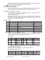
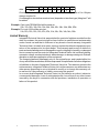
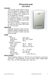
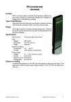
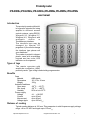
Proximity reader
iPR-A5RSx, iPR-A5W2x, i PR-A5W3x, iPR-A5W4x, PR-A5WSx, iPR-A5TMx
user manual
Introduction
The proximity reader with buildin keypad is intended for being
applied in different access
control systems, using RS232,
Wiegand 26, Wiegand 37,
Wiegand 42, Wiegand with
automatic
choice
or
TouchMemory interface.
The interface type may be
changed by special PC
programm. If you need to change
the interface type please call
your distributor.
The reader is putted in elegant
plastic case with membrane
keypad and two color LED
indicators on front pannel.
Types of tags
The reader operates with
amplitude modulation (ASK)
proximity cards. Type of tag is selected by programmator.
Benefits
Case
Material
Dimensions
Weight
Ambient Conditions
Oper. temp.
Stor. temp.
Humidity
Power supply
Voltage
Current
Max current
Voltage ripple
ABS plastic
115 х 72 х 19 mm
120 g
-20 0С ... +55 0С;
-30 0С … +80 0С;
95% rel. at +25 0C
+8. . . +18 VDC
up to 50 mA
up to 80 mA
up to 500 mVp-p.
Distance of reading
Typical reading distance is 120 mm. This parameter is valid for power supply voltage
range +8 to +18 VDC and ripple up to 150 mVp-p.
http://www.itvsystems.com.ua
Integrated Techical Vision. Ltd
1
Wiring
The reader is equipped with 8-wire interface.
W2 / W3 / W4 / WS
Colour
Green
White
Red
Black
Brown
Orange
Blue
Yellow
TouchMemory
Data 0
Data 1
R S 232
Assignment
Rx
Tx
+V
GND
Red Led
Green Led
B eep
Hold
+V
GND
–
–
–
Hold
+V
GND
Red Led
Green Led
B eep
Hold
iButton
–
Table . The wires assignment.
AWG22 multiwire signal cable is recommended. In this case maximum cable length up
to 100 meters can be obtained*.
Type of interfaces
The proximity reader with build-in keypad is intended for application in different
access control systems, using RS232, Wiegand 26, Wiegand 37, Wiegand 42, Wiegand
with automatic choice** or TouchMemory interface.
Mounting
Mount the reader on the wall close to the lock.
Do not place the reader on metal surfaces,since it causes to reading distance decreasing.
If more than one reader is used in the system, place them at 50 cm minimal distance
from one another, otherwise a reading distance will be decreased.
Fix back plate on the wall on the place where the reader will be mounted. Prepare all
wires for connection and connect the wires with the reader according to Table 1 and
User Manual of the controller to be utilized.
The Reader Operation
RFID Card Code Reading*
The card code reading is annunciated by built-in buzzer and LED lamp according to
interface type and annunciation mode (see Section «Data transfer and Annunciation»).
Next card reading is available after 0.75 sec if the previous card was removed from
reader sensing area.
Code Entering
Push the [#] button to finish the code entering. Push the [*] button to cancel wrong
code. Pushing of every button is indicated by buzer sound.
Hold Mode
* Not for RS232 interface
** For FSK cards only
2
Integrated Technical Vision Ltd
http://www.itvsystems.com.ua
Reader turns into hold mode If yellow wire is closed to ground. In this mode reader
does not read cards, thus current consumption decreases.
Do not apply voltage to yellow wire!
Data transfer and Indication
The reader is provided with two-colour LED indicator and buzzer. LED and buzzer
function according to interface type programmed and annunciation mode.
Wiegand or TouchMemory Interface
LED and buzzer switching on is possible automaticly or by grounding of the
corresponding wire according to the table 2.
Table 2. Annunciation mode:
Data transmission from reader complies with standard Wiegand26, Wiegand37,
Wiegand42 or TouchMemory protocols. Protocol for TouchMemory interface from family
01 (to satisfy the requirements DS1990).
Interface RS232
00
01
02
03
04
05
06
07
Buzzer
Beep on card read
Control from outside
Beep on card read
Control from outside
Beep on card read
Control from outside
Beep on card read
Control from outside
Red LED
LED normally on, switch off at reading
LED normally on, switch off at reading
Switch off
Switch off
LED normally on, switch off at reading
LED normally on, switch off at reading
Control from host
Control from host
Green LED
Blinking at reading
Blinking at reading
Blinking at reading
Blinking at reading
Control from host
Control from host
Control from host
Control from host
To control annunciation send control packet to the reader. Packets should be transmitted with 2 400 baud rate, 8 bit data, no parity, 1 stop bit.
Packet format:
bi t
byte 0
7
0
byte 1
–
byte 2
green
6
1
5
0
red LED
–
blinking
green LED
–
blinking
4
0
–
–
3
1
red
LED lit
–
2
0
1
0
0
1
–
–
–
buzzer
pulsatory
–
buzzer
uninterruptedly
1 – corresponds LED or buzzer switched on. LED blinking and buzzer pulsatory
control bits have highest priority.
Annunciation does not change until next control packet received.
Reader transmits data as follows:
# of byte
Read of card
Read of PIN code
http://www.itvsystems.com.ua
0
23h
21h
1...10
data
data
11
checksum
checksum
Integrated Techical Vision. Ltd
12
0D h
0D h
3
data:
bi t
Value
7
0
6
0
5
1
4
1
3
x
2
x
1
x
0
x
Checksum: exclusive or low nibbles of bytes from 1 to 10. High nibble of 1 to 10 bytes
always must be 3h.
If codelength is shorter than maximal one (depends on interface type) liding hex F will
be added.
Example: Card code 7E000460AA will be send as:
23h, 37h, 3Eh, 30h, 30h, 30h, 34h, 36h, 30h, 3Ah, 3Ah, 3Bh, 0Dh.
Example: Pin code 1234 will be send as:
21h, 3Fh, 3Fh, 3Fh, 3Fh, 3Fh, 3Fh, 31h, 32h, 33h, 34h, 34h, 0Dh.
Limited Warranty
Integrated Technical Vision Ltd. warrants that for a period of eighteen months from the
date of purchase, the product shall be free of defect in materials and workmanship
under normal use and that in fulfilment of any breach of such warranty, Integrated
Technical Vision ltd. shall, at its option, repair or replace the defective equipment upon
return of the equipment to its repair depot. This warranty applies only to defects in
parts and workmanship and not damaged incurred in shipping or handing, or damaged
due to causes beyond the control of Integrated Technical Vision Ltd. such as lightning,
excessive voltage, mechanical shock, water damage, or damage arising out of abuse,
alteration or improper application of the equipment.
The foregoing warranty shall apply only to the original buyer, and is and shall be lieu
of any and all other warranties, whether expressed or implied and of all other obligations
or liabilities on the part of Integrated Technical Vision Ltd. This warranty contains the
entire warranty. Integrated Technical Vision Ltd. neither assumes, nor authorizes any
other person purporting to act on its behalf to modify or to change this warranty, nor
to assume for it any warranty or liability concerning this product.
In no event shall Integrated Technical Vision Ltd. be liable for any direct, indirect or
consequential damages. Loss of anticipated profits, loss of time or any other losses
incurred by the buyer in connection with the purchase, installation or operation or
failure of this product.
4
Integrated Technical Vision Ltd
http://www.itvsystems.com.ua