1
“There Is No Substitute for Experience”
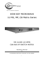
DOW-KEY MICROWAVE
1U MS, MP, CB Matrix Series
MS-1U18S-1/6-GPIB
CAN BUS RF SWITCH MATRIX
Operator’s Manual
Rev 2
THE RF/MICROWAVE SWITCHING TECHNOLOGY SOLUTION COMPANY
i
Copyright Dow-Key Microwave Corporation 2010, all rights
reserved.
Information in this publication supersedes that in all previously
published material. Specifications and price change privileges
reserved.
Printed in the U.S.A.
Dow-Key is a registered trademark of Dow-Key Microwave Corp.
Document Number:
49101-261 Revision 2
4822 McGrath Street, Ventura, CA 93003
Tel: (805) 650-0260 Fax: (805) 650-1734
Visit at www.dowkey.com
ii
WARRANTY
Dow-Key Microwave Corporation warrants this product to be free from defects in
material and workmanship for a period of 1 year from date of shipment. This warranty
does not apply to defects resulting from product tampering or modification without DowKey’s express written consent. This warranty also does not apply to software, nonrechargeable batteries, power supplies, or problems arising from normal wear or failure
to follow instructions.
To exercise this warranty, contact Dow-Key Microwave headquarters in Ventura,
California. You will be given prompt assistance and return instructions. Send the
product, transportation prepaid, to the Dow-Key headquarters. Repairs will be made
and the product returned within the quoted period of time, transportation prepaid.
Repaired or replaced products are warranted for the balance of the original warranty
period, or at least 90 days.
NEITHER DOW-KEY MICROWAVE CORPORATION NOR ANY OF ITS EMPLOYEES
SHALL BE LIABLE FOR ANY DIRECT, INDIRECT, SPECIAL, INCIDENTAL OR
CONSEQUENTIAL DAMAGES ARISING OUT OF THE USE OF ITS INSTRUMENTS
AND SOFTWARE EVEN IF DOW-KEY MICROWAVE CORPORATION HAS BEEN
ADVISED IN ADVANCE OF THE POSSIBILITY OF SUCH DAMAGES. SUCH
EXCLUDED DAMAGES SHALL INCLUDE, BUT ARE NOT LIMITED TO: COSTS OF
REMOVAL AND INSTALLATION, LOSSES SUSTAINED AS THE RESULT OF INJURY
TO ANY PERSON, OR DAMAGE TO PROPERTY.
iii
Manual Revision History
The revision history shown below lists all revisions and addendums created for this manual. The
revision level increases numerically as the manual undergoes subsequent updates. Addendums
are released between revisions and contain important change information that the user should
incorporate immediately into the manual. When a new revision is created, all addendum
associated with the previous revision of the manual are incorporated into the new revision of the
manual. Each new revision includes a revised copy of this history page.
Revision 1 (Document Number 49101-261) …………………………. June 2013
Original Release
Revision 2 ……………………………………..……………………….. October 2013
Corrected section 7.3
- Max number of concatenated commands send in one string is 8.
- Max number of character that can be read (received) at once is 100.
Correction section 7.5.3
- Updated description paragraph.
iv
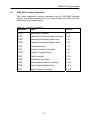
Table of Contents
1 General Information...................................................................................................... 1 1.1 Introduction ........................................................................................................ 1 1.2 MS Matrices ....................................................................................................... 2 1.3 MP Matrices ....................................................................................................... 3 1.4 CB Matrices........................................................................................................ 4 1.5 Technical Specifications ..................................................................................... 5 1.6 Safety Precaution ............................................................................................... 6 1.7 Inspection ........................................................................................................... 6 1.8 Maintenance....................................................................................................... 6 1.9 Repacking for shipment ..................................................................................... 6 2 System Layout ............................................................................................................. 7 2.1 Front Panel Layout ............................................................................................. 7 2.2 Rear Panel Layout ............................................................................................. 8 2.3 Top View Layout ................................................................................................ 9 2.4 RF configuration ............................................................................................... 10 3 Connections ............................................................................................................... 11 3.1 Power Connection ............................................................................................ 11 3.1.1 Line Voltage............................................................................................... 11 3.1.2 Line Power Connection.............................................................................. 11 3.1.3 Line Fuse Replacement ............................................................................. 11 3.2 Ground Connection .......................................................................................... 12 3.3 RS232 Connection ........................................................................................... 13 3.4 CAN Bus Connection ....................................................................................... 14 3.5 GPIB Control Connection ................................................................................. 15 3.5.1 GPIB Control Connector ............................................................................ 15 3.5.2 Interface Signals ........................................................................................ 16 3.5.3 Data Lines ................................................................................................. 16 3.5.4 Handshake Lines ....................................................................................... 17 3.5.5 Interface Management Lines ..................................................................... 17 3.6 USB Port .......................................................................................................... 18 4 Configuring the Matrix for Operation .......................................................................... 19 4.1 Matrix Configuration ......................................................................................... 19 4.2 Dow-Key CAN bus switches............................................................................. 19 4.3 Adding and Deleting Switches.......................................................................... 20 5 Manual (LOCAL) Operation ........................................................................................ 22 5.1 The Keypad / LCD Interface ............................................................................. 22 5.2 Main Menu ....................................................................................................... 24 5.2.1 Switching Operations ................................................................................. 24 5.2.2 Error Operations ........................................................................................ 26 5.2.3 System Settings ......................................................................................... 27 5.2.4 Ethernet Options ........................................................................................ 29 5.2.5 LCD Options .............................................................................................. 29 5.2.6 Set RS232 Baud Rate ............................................................................... 29 5.2.7 Set GPIB Address ..................................................................................... 29 6 IEEE 488.2 Register model .................................................................................... 30 6.1 Introduction to IEEE 488.2 ............................................................................... 30 6.2 Condition Register ............................................................................................ 30 6.3 Event Register.................................................................................................. 30 vi
6.4 Enable Register................................................................................................ 30 6.5 The Status Byte Register ................................................................................. 31 6.6 The Standard Event Register ........................................................................... 32 6.7 IEEE 488.2 Common Commands .................................................................... 33 7 Remote Operation .................................................................................................. 34 7.1 Introduction to SCPI ......................................................................................... 34 7.2 Command Syntax Structure ............................................................................. 34 7.3 Command Separators and conventions ........................................................... 35 7.4 Common Commands ....................................................................................... 36 7.4.1 *CLS .......................................................................................................... 36 7.4.2 *ESE .......................................................................................................... 36 7.4.3 *ESE? ........................................................................................................ 37 7.4.4 *ESR? ........................................................................................................ 37 7.4.5 *IDN? ......................................................................................................... 38 7.4.6 *OPC ......................................................................................................... 38 7.4.7 *OPC? ....................................................................................................... 39 7.4.8 *RST .......................................................................................................... 40 7.4.9 *STB? ........................................................................................................ 40 7.4.10 *SRE ...................................................................................................... 41 7.4.11 *SRE? .................................................................................................... 41 7.4.12 *WAI ....................................................................................................... 41 7.5 System Commands .......................................................................................... 42 7.5.1 SYST:ERR?............................................................................................... 42 7.5.2 SYST:SERIALNUMBER? .......................................................................... 46 7.5.3 SYST:STATUS? ........................................................................................ 47 7.5.4 SYST:SCREENSAVER? ........................................................................... 48 7.5.5 SYST:SCREENSAVER x .......................................................................... 48 7.5.6 SYST:GPIBADDRESS? ............................................................................ 49 7.5.7 SYST:GPIBADDRESS x............................................................................ 49 7.6 Switch [Module] Command Set ........................................................................ 50 7.6.1 :SWITch<id>[:VALue] <number> ............................................................... 50 7.6.2 Setting switch x to position n ..................................................................... 51 7.6.3 Requesting Switch x current position ......................................................... 52 Appendix A .................................................................................................................... 56 Technical Specifications ............................................................................................ 56 Appendix B .................................................................................................................... 57 RF Configuration........................................................................................................ 57 Matrix RF diagram ..................................................................................................... 57 vi
1 General Information
1.1
Introduction
The Dow-Key Microwave MS, MP, CB Switch Matrix series are
electromechanical RF matrices. They come equipped with ENET (Ethernet) or
GPIB (IEEE 488) port which allows the user to easily access the matrix
remotely. This manual addresses the GPIB (IEEE 488) version. Other
interfaces included are an RS-232 port, a USB (used as virtual serial port) and
a CAN Bus port. The 1U models are 1 Rack Unit high (1.75”) and come
equipped with a LCD/keypad front panel display for manual (Local) operation.
These models are not intended to be used to power or control anything other
than Dow-Key supplied switches. Connection of other CAN Bus products or
other devices not described herein will void quality certifications and the
warranty.
This user manual covers all three matrix series since most features are the
same among the various models. The user shall focus on the matrix series of
interest and skip any section that does not pertain to his/her matrix.
Information specific to your model (like technical specifications and RF
configuration) can be found in appendices at the end of this manual.
1
General Information
1.2
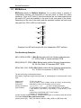
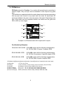
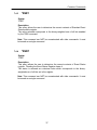
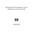
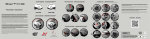
MS Matrices
MS-Series stands for Multiple Switches. It is a matrix where a number of
independent switches are populated on the rear panel or inside the matrix
enclosure. From an RF point of view the switches are not interconnected and
all switch’s RF ports are available to the user on the rear panel of the matrix.
Depending on the size of the switch and the quantities needed, the matrix size
can grow from 1RU to 4RU (or even larger).
Input
SW1
Out 1
Out 2
Out 3
Out 4
Input
SW2
Out 1
Out 2
Out 3
Out 4
Input
SW3
Out 1
Out 2
Out 3
Out 4
Input
SW4
Out 1
Out 2
Out 3
Out 4
Example of an MS series matrix with four independent SP4T switches.
Part Numbering Examples:
MS-1U18S-4/X-GPIB A Multi Switch matrix with the following characteristics:
1U, 18 GHz, SMA, 4 transfer switches, GPIB
MS-2U26S-4/6T- GPIB A Multi Switch matrix with the following characteristics:
2U, 26 GHz, SMA, 4 Terminated SP6T, GPIB
MS-4U18N-12/10- GPIB A Multi Switch matrix with the following characteristics:
4U, 18 GHz, N connectors,12 SP10T, GPIB
The part numbering is interpreted as follows:
MS-[chassis size][frequency][connector]-[number of switches]/[type of switch]-[remote control
type]
[chassis size]:
[frequency]:
[connector]:
[number of switches]:
[type of switch] :
1U | 2U | 3U | 4U etc.
12 (for 12.4 GHz) | 18 (for 18 GHz | 26 (for 26.5 GHz) | 40 (for 40 GHz)
B (for BNC) | N (for N) | S (for SMA) | K (for 2.9 mm)
1 | 2 | 3 | 4 | 5 |… |16
(or more if chassis size allows)
2T (terminating one port DPDT terminated SPDT) | X (for DPDT)
| 4 (for SP4T) | 6 (for SP6T) | 8 (for SP8T) | 10 (for SP10T) |12 (for
SP12T).
If switch type is terminated, add ‘T’ to the number.
Example: 6T (terminated SP6T)
[number of switches]/[type of switch]: If different switch types are combined, repeat this section
as needed. Example: MS-1U18S-2/X-2/6T-GPIB
[remote control type]: ENET (for Ethernet, RS-232, USB) | GPIB ( for IEEE-488, USB)
2
General Information
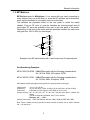
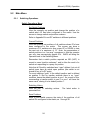
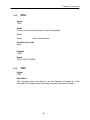
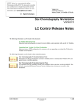
1.3 MP Matrices
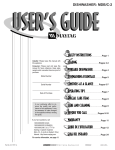
MP-Series stands for Multiplexer. It is a matrix with one input connecting to
many outputs (only one at the time) or, since the RF switches are bi-directional,
many inputs connected to one output (only one at the time).
The switches are populated either on the rear panel or inside the matrix
chassis. From an RF point of view the switches are interconnected and all
input/output RF ports are available to the user on the rear panel of the matrix.
Depending on the size of the switch and the quantities needed, the matrix size
can grow from 1RU to 4RU (or even larger).
Input
SW2
Out 1
Out 2
Out 3
Out 4
SW3
Out 5
Out 6
Out 7
Out 8
SW4
Out 9
Out 10
Out 11
Out 12
SW5
Out 13
Out 14
Out 15
Out 16
SW1
Example of an MP series matrix with 1 input/output and 16 outputs/inputs.
Part Numbering Examples:
MP-4U18S-100-GPIB A Multi Plex matrix with the following characteristics:
4U, 18 GHz, SMA, 100 outputs, GPIB
MP-4U18S-20- GPIB
A Multi Plex matrix with the following characteristics:
4U, 18 GHz, SMA, 20 outputs, GPIB
MP-[chassis size][frequency][connector]-[number of ports]-[remote control type]
[chassis size]:
[frequency]:
[connector]:
[number of ports]:
1U | 2U | 3U | 4U etc.
12 (for 12.4 GHz) | 18 (for 18 GHz) | 26 (for 26.5 GHz) | 40 (for 40 GHz)
B (for BNC) | N (for N-type) | S (for SMA) | K (for 2.9 mm)
20 | 30 | 40 | 50 | 60 | 70 | 80 | 90 | 100 (and more ports if chassis size
allows)
If ports are internally terminated, add ‘T’ to the number.
Example: 20T, .. , 100T
[remote control type]: ENET (for Ethernet, RS-232, USB) | GPIB (for IEEE-488, USB)
Note: There is always one only input and a certain number of outputs. So no need to indicate
the ‘1’ (for the input).
3
General Information
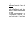
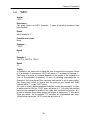
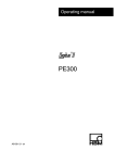
1.4 CB Matrices
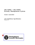
CB-Series stands for Crossbar. It is a matrix with several inputs connecting to
several outputs. Only one input can be connected to one output at any given
time.
The switches are populated inside the matrix chassis and are interconnected so
that any input can connect to any output and vice versa. All input/output RF
ports are available to the user on the rear panel of the matrix. Depending on the
size of the switch and the quantities needed, the matrix size can grow from
2RU to 4RU (or even larger).
Input 1
Input 2
Input 3
Input 4
1
2
SW1 3
4
1
2
3 SW5
4
1
2
SW2 3
4
1
2
3 SW6
4
1
2
SW3 3
4
1
2
3 SW7
4
1
2
SW4 3
4
1
2
3 SW8
4
Output 1
Output 2
Output 3
Output 4
Example of a CB series matrix with 4 inputs and 4 outputs.
Part Numbering Examples:
CB-4U18S-10X10-GPIB A CrossBar matrix with the following characteristics:
4U, 18 GHz, SMA, 10 inputs 10 outputs, GPIB
CB-4U18N-8X8- GPIB
A CrossBar matrix with the following characteristics:
4U, 18 GHz, N connectors, 8 inputs 8 outputs, GPIB
CB-2U18S-4X4- GPIB
A CrossBar matrix with the following characteristics:
2U, 18 GHz, SMA, 4 inputs 4 outputs, GPIB
CB-[chassis size][frequency][connector]-[number of inputs]X[number of outputs]-[remote control type]
[chassis size]:
[frequency]:
[connector]:
[number of inputs]:
[number of outputs]:
[remote control type]:
1U | 2U | 3U | 4U etc.
12 (for 12.4 GHz) | 18 (for 18 GHz) | 26 (for 26.5 GHz) | 40 (for 40 GHz)
B (for BNC) | N (for N) | S (for SMA) | K (for 2.9 mm)
2 | 3 | 4 | 5 … 10 | 12 | 16| 20 (or more if chassis size allows)
2 | 3 | 4 | 5 … 10 | 12 | 16| 20 (or more if chassis size allows)
ENET (for Ethernet, RS-232, USB) | GPIB (for IEEE-488, USB)
4
General Information
1.5 Technical Specifications
Refer to appendix A
5
General Information
1.6
Safety Precaution
Safety precautions should be observed before using this product and any
associated instrumentation. This product is intended for use by qualified
personnel who recognize the safety precautions required to avoid possible
injury.
1.7
Inspection
The Matrices were carefully inspected, both electrically and mechanically before
shipment. After unpacking all items from the shipping carton, check for any
obvious signs of physical damage that may have occurred during transit.
Report any damage to the shipping agent immediately. Save the original
packing carton for possible future reshipment. The following items are included
with every Model matrix order.
Switch matrix
Switch matrix Operation Manual
Power Cord, Part Number 40203-005
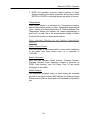
1.8
Maintenance
The matrix requires no periodic maintenance. Should any problems arise,
contact Dow-Key Microwave immediately for necessary repairs.
These
systems are not field repairable.
1.9
Repacking for shipment
Should it become necessary to return the matrices for repair, carefully pack the
unit in its original packing carton or the equivalent, and follow these instructions:
Call the Repair Department at 1-805-650-2327 for a Return Material
Authorization (RMA) number.
Advise as to the warranty status of the matrix.
Write ATTENTION REPAIR DEPARTMENT and the RMA number on
the shipping label.
6
2 System Layout
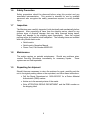
2.1
Front Panel Layout
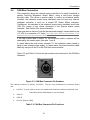
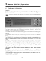
Figure 2-1 shows the 1U Model general layout, which includes:
2 handles
Three LED, LCD and keypad
Figure 2-1, 1U Front Panel Layout
7
System Layout
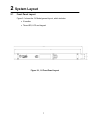
2.2
Rear Panel Layout
Figure 2-2 shows an example of a 1U model rear panel general layout. All
models have common parts which include:
Power Entry Module with built in Fuse
Chassis Ground Post
9-Pin D-Sub Female RS232 Connector
4-Pin XLR Female CAN Bus / 12V power (output) Connector
GPIB (IEEE 488) 25 pin Centronics Connector
USB type A Connector
Other parts that are not common to all models are Coaxial RF switches and/or
RF connectors.
GND stud
Figure 2-2, 1U MS series (with external switches) Rear Panel Layout
8
System Layout
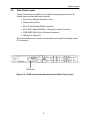
2.3
Top View Layout
Figure 2-3 shows the top view layout of all models.
Figure 2-3, Top View of 1U Models
9
System Layout
2.4
RF configuration
Refer to appendix B.
10
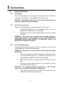
3 Connections
3.1
3.1.1
Power Connection
Line Voltage
The matrix operates from a line voltage in the range of 110V to 240V at a
frequency of 50 or 60Hz. Line voltage selection is automatic.
CAUTION: Operating the unit on an incorrect line voltage may cause
damage, possibly voiding the warranty.
3.1.2
Line Power Connection
Perform the following steps to connect the matrix to line power:
1.
Connect the female end of the supplied power cord to the
grounded AC receptacle on the rear panel.
2.
Connect the other end of the supplied power cord to a grounded
AC outlet.
WARNING: The power cord supplied with the matrix contains a
separate ground for use with grounded outlets. FAILURE TO USE A
GROUNDED OUTLET MAY RESULT IN PERSONAL INJURY OR
DEATH DUE TO ELECTRIC SHOCK.
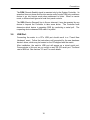
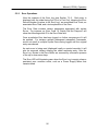
3.1.3
Line Fuse Replacement
A rear panel fuse protects the power line input of the matrix. If the line fuse
needs replacement, perform the steps below:
WARNING: Disconnect the line cord from the unit before changing
the line fuse.
1.
The fuse is located in a holder in the power module unit above
the AC receptacle (figure 3-1). At the top is a small tab, use a
small bladed screwdriver to release the fuse holder.
2.
Slide the fuse holder out to gain access to the fuse carrier and
fuse.
3.
Remove the carrier with the blown fuse, and replace with the
correct type listed in Table 3-1.
CAUTION: For continued protection against fire or unit damage,
replace the fuse only with the type and rating listed.
4.
Install the fuse carrier in the fuse holder, then insert the fuse
holder back in the power entry module.
11
Connections
Insert small bladed screwdriver
to release the fuse.
Figure 3-1, Power Entry Module
Line
Voltage
Fuse Rating
Manufacturer
Manufacturer Part No.
110-240V
1A, slow blow, 250Vac, ¼” x 1-1/4”
Bel Fuse Inc.
3SB 1-R
Table 3-1, AC Line Fuse Information
3.2
Ground Connection
The rear panel GND ground screw (refer figures 2-2, 2-3 and 2-4) should be
connected to safety earth ground using #18 AWG or larger wire.
12
Connections
3.3
RS232 Connection
The switch matrix may be operated over this connection (See Section 6 for a
description of the commands). The RS232 connection is configured with these
default settings: 9600 Baud, 8 bit data, no parity, 1 stop bit.
The baud rate can be changed thru the keypad / LCD to:
1200, 2400, 4800, 9600, 19200, 38400, 57600,115200 bits/sec
Figure 3-2 and Table 3-2 show the pin numbers and functions for the RS232
female connector.
5
9
1
6
Figure 3-2, RS232 Female Connector Pin Numbers
Pin 1
Pin 2
Pin 3
Pin 4
Pin 5
Pin 6
Pin 7
Pin 8
Pin 9
NC
Transmit
Receive
NC
Ground
NC
NC
NC
NC
Table 3-2, RS232 Female Connector Pin Functions
13
Connections
3.4
CAN Bus Connection
This connection allows the internal matrix controller to be easily interfaced to
another Dow-Key Microwave Switch Matrix, using a one-to-one (straight
through) cable. This allows a master matrix to control an extension matrix.
However, the extension matrix being interfaced must not have any internal,
intelligent controller; it must be a simple RF Switch Matrix extension.
Furthermore, the switches in the extension matrix being interfaced must have
CAN ID’s unique to any others connected to the internal master matrix
controller. See Section 4 for more information.
Care must also be taken to limit the internal power supply’s current draw on the
+12 VDC to a maximum of 7 Amps. Note that this includes all switches of the
master matrix and the extension matrix combined.
If the total current draw is below 7A, the extension matrix’s switches will be
powered by the master matrix (thru pins 1 and 4).
In cases where the total current exceeds 7A, the extension matrix needs to
have its own internal power supply. In these cases, the interconnection cable
shall only use pins 2 and 3 for the CAN bus communication.
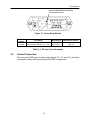
Figure 3-3 and Table 3-3 show the pin numbers and functions for the CAN Bus
connector.
4
1
2
3
Figure 3-3, CAN Bus Connector Pin Numbers
The mating connector is Deltron 701-0400. The pin outs (embossed on connector faces)
are:
1. +12 VDC, 7A max (this current is for master and extension matrices combined. See
Individual switch data sheets for current draw).
2.
CAN LO
3.
CAN HI
4. +12 VDC Return (GND)
Table 3-3, CAN Bus Connector Pin Functions
14
Connections
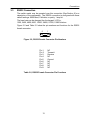
3.5
GPIB Control Connection
On the rear panel of the matrix is a GPIB (IEEE-488) control port which gets
connected to the GPIB port of a computer (controller) using a shielded IEEE488 interface cable with metric mounting screws. Figure 3-4 shows the
connector configuration and Table 3-4 shows the signal assignments.
3.5.1
GPIB Control Connector
You can link devices in either a linear, star or combination configuration using a
shielded 24-conductor cable. The standard IEEE-488 cable has both a plug
and receptacle connector on both ends. This connector is the Amphenol
CHAMP or Cinch Series 57 MICRO RIBBON type. See figure 3-4.
Figure 3-4 GPIB Control Connector
12
1
24
13
The following restrictions apply for normal operation when attaching instruments
to the GPIB:
A maximum separation of 4 meters between any two instruments and an
average separation of 2 meters over the entire bus.
A maximum total cable length of 20 meters.
No more than 15 devices on the bus, with no less than two-thirds
powered on.
No two instruments having the same address.
If you are unable to meet the above restrictions, the use of bus extenders is
recommended.
15
Connections
3.5.2
Interface Signals
The GPIB (IEEE-488) interface system consists of 16 signal lines and 8 ground
lines. The 16 signal lines are divided into 3 groups (8 data lines, 3 handshake
lines, and 5 interface management lines). See table 3-4 for the signal
assignments.
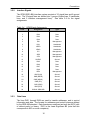
Table 3-4
3.5.3
GPIB Signal Assignments
Pin #
Designation
Type
1
DI01
Data
2
DI02
Data
3
DI03
Data
4
DI04
Data
5
EOI
Management
6
DAV
Handshake
7
NRFD
Handshake
8
NDAC
Handshake
9
IFC
Management
10
SRQ
Management
11
ATN
Management
12
SHIELD
Ground
13
DI05
Data
14
DI06
Data
15
DI07
Data
16
DI08
Data
17
REN
Management
18
GND (DAV)
Ground
19
GND (NRFD)
Ground
20
GND (NDAC)
Ground
21
GND (IFC)
Ground
22
GND (SRQ)
Ground
23
GND (ATN)
Ground
24
SIGNAL GROUND
Ground
Data Lines
The lines DIO1 through DIO8 are used to transfer addresses, and to control
information and data. The formats for addresses and control bytes are defined
by the IEEE-488 standard. Data formats are undefined and may be ASCII (with
or without parity) or binary. DIO1 is the Least Significant Bit (note that this
corresponds to bit 0 on most computers).
16
Connections
3.5.4
Handshake Lines
The three handshake lines (NRFD, NDAC, DAV) control the transfer of
message bytes among the devices and form the method for acknowledging the
transfer of data. This handshaking process guarantees that the bytes on the
data lines are sent and received without any transmission errors and is one of
the unique features of the IEEE-488 bus.
The NRFD (Not Ready for Data) handshake line is asserted by a listener to
indicate it is not yet ready for the next data or control byte. Note that the
Controller will not see NRFD released (i.e., ready for data) until all devices have
released it.
The NDAC (Not Data Accepted) handshake line is asserted by a Listener to
indicate it has not yet accepted the data or control byte on the data lines. Note
that the Controller will not see NDAC released (i.e., data accepted) until all
devices have released it.
The DAV (Data Valid) handshake line is asserted by the Talker to indicate that
a data or control byte has been placed on the data lines and has had the
minimum specified stabilizing time. The byte can now be safely accepted by
the devices.
3.5.5
Interface Management Lines
The five interface management lines (ATN, EOI, IFC, REN, SRQ) manage the
flow of control and data bytes across the interface.
The ATN (Attention) signal is asserted by the controller to indicate that it is
placing an address or control byte on the data bus. ATN is released to allow
the assigned Talker to place status or data on the data bus. The Controller
regains control by reasserting ATN; this is normally done synchronously with
the handshake to avoid confusion between control and data bytes.
The EOI (End or Identify) signal has two uses. A talker may assert EOI
simultaneously with the last byte of data to indicate end-of-data. The Controller
may assert EOI along with ATN to initiate a parallel poll. Although many
devices do not use parallel poll, all devices should use EOI to end transfers
(many currently available ones do not).
The IFC (Interface Clear) signal is asserted only by the System Controller in
order to initialize all device interfaces to a known state. After releasing IFC, the
System Controller is the Active Controller.
17
Connections
The REN (Remote Enable) signal is asserted only by the System Controller. Its
assertion does not place devices into remote control mode; REN only enables a
device to go into remote mode when addressed to listen. When in remote
mode, a device should ignore its local front panel controls.
The SRQ (Service Request) line is like an interrupt: it may be asserted by any
device to request the Controller to take some action. The Controller must
determine which device is asserting SRQ by conducting a serial poll. The
requesting device releases SRQ when it is polled.
3.6
USB Port
Connecting the matrix to a PC’s USB port should result in a “Found New
Hardware” event. Follow the instructions until prompted for the new hardware
device’s driver, which may be located on the CD shipped with the matrix.
After installation, the matrix’s USB port will appear as a virtual serial port.
Communicate to this port as you would on any RS 232 serial port. The baud
rate is 9600 b/s. See sections 3.3 and 7 for more details.
18
4 Configuring the Matrix for Operation
4.1
Matrix Configuration
The ‘brain’ inside Dow-Key Matrices, referred to as the “Matrix Controller”, has
been designed to be as generic as possible in regards to how many switches
and what positions it may control. Therefore, the matrix must first be informed
as to the set of switches it is able to control before it can operate successfully,
and this information must be updated as switches are added and deleted to the
matrix or connected to the CAN bus port on the rear of the matrix (see section
3.4). The knowledge of what switches are to be controlled and how many
positions each of those switches has is known as the matrix’s Configuration
Data.
In addition to switch information, the Matrix Configuration also contains other
information such as the base MAC address (for Ethernet based matrices), unit’s
Serial Number, alarm enabling, Model Name, etc. This information must
remain intact for the matrix to operate properly.
The matrix configuration is already performed at the factory and does not need
to be done by the user unless the Matrix Controller board has been replaced.
Adding and removing switches (see sections 4.2.3) automatically updates the
matrix configuration. No further action is required by the user.
The topics discussed in sections 4.2 and 4.3 are not needed during normal
operation of your matrix. These sections are here for informational purpose and
in the event the RF configuration of the matrix is being modified by
adding/removing switches.
4.2
Dow-Key CAN bus switches
A CAN Bus switch may assume a maximum CAN ID of 127. Individual
switches delivered by Dow-Key will be programmed with either ID=0 or ID=1,
depending on the particular procedure utilized to manufacture the switch. The
matrix provides the means to change CAN Bus ID’s at will.
A CAN Bus switch may have a maximum of 255 positions (0 through 254). 255
is reserved as a return value indicating that the switch is either in an erroneous
position, or is reported to the Operator when a switch fails to respond to a query
for current position.
A switch whose ID is 0 is referred to as a “zero switch”, or also a “0 switch”. A
switch whose ID is other than 0 is referred to as an “N switch”.
Zero switches and N switches have different properties:
Only a zero switch may change into an N switch.
An N switch may not change its ID to anything other than 0.
A zero switch will not respond to commands to change or report its position.
A zero switch will not respond to queries for switch position closure counts.
A zero switch may not be added to a Configuration (see below) as an ID=0.
19
Configuring the Matrix
4.3
Adding and Deleting Switches
The following rules apply when adding a switch to the Matrix Configuration (the
desired ID to add is referred to as the “target ID”):
‐
The desired switch to ADD must be connected to the matrix before
executing the ADD procedure.
‐
If the connected switch is a 0 switch AND the target ID is not yet configured
AND a switch possessing the target ID is not already connected, then the 0
switch will change its ID to the target ID and the Configuration will be
updated.
‐
If the connected switch is a 0 switch AND the target ID is already configured
AND a switch possessing the target ID is not already connected, AND the 0
switch’s number-of-positions data matches that of the Configuration’s, then
the 0 switch will change its ID to the target ID.
‐
If the connected switch is an N switch AND the target ID=N is not yet a
configured ID, then the N switch will be added, i.e. the Configuration will be
updated.
‐
If the connected switch is an N switch AND the target ID=N is already a
configured ID, AND the N switch’s number-of-positions data matches that of
the Configuration’s, then the N switch will be added, i.e. the Configuration
will be updated (actually, the ID isn’t really added since the ID is already
configured, however a Configuration match is performed).
The following rules apply when deleting a switch from the Configuration (the
desired ID to delete is referred to as the “target ID”):
‐ Only an N switch may be deleted from a Configuration; 0’s are not
Configurable .
‐ If the N switch to delete is connected and is not a Configured ID, AND a zero
switch is not connected, then the N switch will be returned to a 0 switch.
‐ If the N switch to delete is connected and is already a Configured ID, AND a
zero switch is not connected, then the N switch will be removed from the
Configuration and its ID set to 0 (i.e. turning the N switch into a 0 switch).
‐ If the N switch to delete is connected and is already a Configured ID, AND a
zero switch is connected, then the N switch will be removed from the
Configuration, but the N switch’s ID will remain N.
‐ If the N switch to delete is not connected and is already a Configured ID, then
the ID will be removed from the Configuration
NOTE:
THE MATRIX MUST BE POWER CYCLED AFTER MAKING ANY CHANGES TO THE
CONFIGURATION BEFORE THOSE CHANGES BECOME FULLY APPARENT.
NOTE:
Keep unused switches stored as 0 switches. Label switches that are dedicated to particular
CAN Bus IDs on the switch’s enclosure.
20
Configuring the Matrix
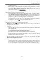
Example procedure:
Before adding it to the Configuration you need to find the switch’s ID. To do this
select Main Menu>System Settings>Find Switch ID and then follow the
instructions in Section 5.2.3 Find Switch ID.
If the switch’s ID found is the one desired to add:
Press the BACK key until you see the Main Menu screen. To ADD the switch,
select Main Menu>System Settings>Add Switch. The LCD will indicate if the
switch to add is a 0 switch and then prompt the user with the next available-toconfigure ID, or the user may enter a different, un-configured ID.
If the switch’s ID is not zero, the LCD will prompt you to add the next availableto-configure ID, and you must enter the connected switch’s ID.
If the switch’s ID found is NOT the switch you wish to add:
Example: In order to change a switch’s ID from N=x to N=y, it must first be
reconfigured as a zero switch.
To do this:
Make sure the N=x switch is connected AND that NO OTHER N=x SWITCHES
ARE CONNECTED
Select Main Menu>System Settings>Delete Switch
Enter the ID (N=x) of the connected switch and its ID will be set to 0
Briefly disconnect and reconnect the switch to allow the switch’s internal
firmware to reboot with its new ID as 0
Now the process to add the switch as N=y may be executed via Main
Menu>System Settings>Add Switch.
Deleting a switch from the matrix configuration data does not require the switch
to be connected. When a switch is deleted while connected, its ID is returned to
0. If it is not connected, it is still removed from the Matrix Configuration Data.
21
5 Manual (LOCAL) Operation
5.1
The Keypad / LCD Interface
Power On:
Position the rocker switch on the rear panel of the Matrix to the ON position (Figures 22) to turn on the matrix.
! Note: The booting sequence will last about 15 seconds. The LCD can appear blank
during this time.
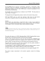
The figure above shows the LCD/Keypad (sometimes referred to as the “User
Interface”, or “UI”) at the top level of UI screens.
The “COMM” LED should normally be blinking green as an indication of normal program
execution.
The “REMOTE” LED, normally dark, will illuminate green when the matrix is in REMOTE
Mode.
The “ERROR” LED, normally green, will illuminate red upon the occurrence of an error
event, or the persistence of several error conditions (see Sections 5.2.1a.5.2.2 and
7.5.1).
The LCD in the figure above shows the top level of the operational screen, which
happens to be a menu; the keypad is used to scroll through and select menu items.
Other screens encountered allow the operator to modify various parameter values; all
such “data fields” are presented with a currently set or default value blinking, prompting
the operator to modify the value. Some screens present multiple data fields, and the
keypad is used to navigate around them.
The keypad’s keys have multiple functions depending on which screen is being
presented.
The keypad’s round, center key is referred to as “ENTER” and serves as “set”, “select”,
“done”, or “return”.
The keypad’s arrow keys (pointing the 4 cardinal directions) are referred to as “UP”,
“DOWN”, “LEFT”, and “RIGHT”.
22
Manual (LOCAL) Operation
UP and DOWN serve as “scroll up”, “scroll down”, “increment”, or “decrement”. Many
data fields’ values are modified by UP and DOWN, and many of those allow the
pressing and holding of the UP and DOWN keys to cause an acceleration of the
incrementing or decrementing.
The keypad’s upper left diagonal key is referred to as UP DIAG. This key serves as
“back”, “clear”, or “escape”.
The keypad’s lower left diagonal key causes no action in the context of any screen.
LEFT and RIGHT serve as “next” and “previous”; these keys are used almost
exclusively to navigate around the user data entry fields many screens present.
Caveats:
The UI device may demonstrate a “speed limit” when it comes to how rapidly the
Operator may actuate keys and still get the correct response on the LCD: the Operator
is encouraged to find a comfortable cadence when operating the keypad.
! Note:
To preserve the life of the LCD, it has a ‘screen saver’ feature. After 5 minutes the LCD
backlight will turn off. Once dark, pressing any key will have no effect other than to reilluminate the backlight.
The matrix will power up in LOCAL Operating Mode. LOCAL Operating Mode means
that the matrix is receiving commands from the front panel (Keypad).
When in LOCAL Operation Mode the matrix will switch automatically in REMOTE mode
as soon as commands coming from a remote control computer are received (GPIB,
Serial or USB). The matrix will return to LOCAL Mode upon the pressing of any key.
The matrix will not accept any other local commands until the operator switches to
LOCAL mode by pushing any button on the keypad.
As stated before, to switch to REMOTE Operation Mode the operator needs to send a
command (GPIB, Serial or USB) by means of a remote control computer.
All LOCAL operation of the matrix is accomplished via the front panel’s Keypad / LCD.
The various screens encountered in the matrix’s operation contain the following
controls:
23
Manual (LOCAL) Operation
5.2
Main Menu
5.2.1
Switching Operations
Switch Operations Menu
Set Switch Positions
View the currently set position and change the position of a
switch who’s ID has been configured to the matrix. Use the
arrows to change switch and position numbers.
Refer to Appendix B to set RF switches in different positions.
Current Positions
View the currently set positions of all switches whose ID’s have
been configured to the matrix. This screen can show a
maximum of 12 switches at a time; press UP or DOWN to view
the next set of a maximum of 12. Note: the presentation of
switch positions is a “one way” experience in that the operator
can only view successively greater ID’s. BACK will bring the
Operator back to the Switching Menu.
Remember that a switch position reported as 255 (0xFF) is
meant to mean “position unknown”, and is often the result of a
switch not responding to a query for position.
Note that all Dow-Key switches have “open” defined, but not all
switch types have an actual open position (the switch is not
closed to any of its RF ports).
For most switches “open” is the default position and is defined
as position 0. But for transfer switches there is no “open”
condition, hence the default position is pos.1. As a result of this,
commanding a transfer switch to pos 0 or pos 1 will have the
same result, closing it to its default position 1.
Switching History
View the last 10 switching actions.
presented first.
The latest action is
Save Positions
Save to non-volatile memory the state of the positions of all
switch ID’s configured to the matrix, as 1 through 30.
24
Manual (LOCAL) Operation
Recall Positions
Recall from non-volatile memory the state of the positions of all
switch ID’s configured to the matrix, saved as 1 through 30, and
set the positions of those switches.
Clear Positions
Cause all switches configured to the matrix to assume their
default position. For most switches this is position 0 (open
positions). Note that all Dow-Key switches have “open” defined,
but not all switch types have an actual open position, such as a
transfer switch. In this case, “open” means “close on its default
position 1”.
Cycle Positions
Step all switches configured to the matrix through all of their
positions. NOTE: the Cycle Position function is intended for use
at the Dow-Key factory during the assembly process. In fact,
the Cycle Position function will generate errors when
commanding a Transfer switch to switch from position 0 to
position 1, which may be ignored. For this reason, the Operator
is discouraged from exercising Cycle Positions.
25
Manual (LOCAL) Operation
5.2.2
Error Operations
View the contents of the Error Log (see Section 7.5.1). Each entry is
displayed with the oldest being first (First In First Out), showing the Error
Record Number (its place in the Error Log), an associated Error Code, an
associated Error Data, and a text explanation of the Error.
The Error Data contains various parameters associated with certain
Errors. For instance, an Error Code 10 “Switch Did Not Respond” will
show the offending switch ID in the Error Data field.
Once a particular Error has been logged, no further occurrences of it will
be entered. For instance multiple subsequent misspelled Commands,
would not result in multiple Syntax Errors being logged until the original
entry was cleared.
As each error is being read (displayed locally or queried remotely) it will
also be removed, always clearing the oldest remaining entry, from the
Error Log. Entries in the Error Buffer are removed by successive presses
of the up or down arrow keys.
The Error LED will illuminate green when the Error Log is empty unless a
persistent error condition exists, such as a Power Supply failure that
remains failed.
26
Manual (LOCAL) Operation
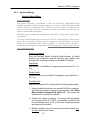
5.2.3
System Settings
System Settings Menu
! Important Note:
The matrix controller is designed to offer the maximum expandability and
flexibility possible and therefore has features common to other Dow-Key matrix
models. The here described ‘Add’, ‘Delete’ and ‘Find Switch ID’ features are
some of those that, although available and fully functioning, should only be
used if needed and appropriate.
Switches may be added and deleted from the Matrix Configuration using these
commands.
For those matrix models with a custom or fixed RF configuration (in other words
where the internal RF switches and its connections are defined on a custom
bases or are established and fixed by design), no switch shall be added or
removed from the matrix configuration. Not following this instruction will result in
a non working matrix!
System Information
View the Dow-Key Matrix Product’s Model Number, its Serial
Number (set at factory), and the Dow-Key part number and
revision level of firmware running on the Matrix Controller.
Add Switch
Add switches to the Matrix Configuration (see Sections 4.1, 4.2,
4.3).
Delete Switch
Delete switches from the Matrix Configuration (see Section 4.1,
4.2, 4.3).
Find Switch ID
Discover and view the ID of any switch by following these steps:
1. Using a matrix with at least one unused CAN Bus connector,
and leaving the switch in question unconnected, select Main
Menu>System Settings>Find Switch ID. The screen will
indicate that no switch is connected.
2. Connect the switch in question. The screen will now display
the unknown switch ID. NOTE: occasionally, the switch will
not immediately report its ID; in this case, simply disconnect
and reconnect the switch.
3. Multiple switches may be connected and disconnected one
at a time while in this screen.
27
Manual (LOCAL) Operation
4. NOTE: this operation “puts the matrix’s switches to sleep”
thereby rendering the matrix inoperable during the process.
ENTER or CLEAR or rebooting returns the matrix to normal.
Temperatures
View current values of a maximum of 4 temperature sensors,
and set thresholds at which an Over Temperature alarm should
occur. Setting all 4 alarm thresholds to 0° Celsius disables Over
Temperature alarms and causes the current temperatures to
read out 0° as well; this is the recommended setting for Matrix
Products that contain no temperature sensors.
Most standard Models do not feature temperature
sensors.
Switch Closure Counts
View the number of times any position of any switch configured
to the matrix has been closed upon, to a maximum of
1,000,000.
Switch Information
View the Part Number, Serial Number, Firmware Number,
Firmware Revision Level, maximum number of positions, its
PCBA Code (factory), and Coil Delay Time, of any switch
configured to the matrix.
Default Settings
This password protected option is used during the assembly
process to set serial number, MAC address (for Ethernet based
matrices) and CAN bus speed and is not intended for Operator’s
use.
28
Manual (LOCAL) Operation
5.2.4
Ethernet Options
Ethernet Menu
Not applicable to GPIB (IEEE-488) models. This menu is not operational.
5.2.5
LCD Options
View and adjust the brightness and contrast of the LCD. Changes made
here are persistent over power down and up.
5.2.6
Set RS232 Baud Rate
View and select the Serial Port’s Baud rate from a set of preselected
values from 1200 to 115,200 b/s (see Section 3.3).
Use the arrows to change the baud rate settings.
Default value is 9600b/s.
5.2.7
Set GPIB Address
View and see the GPIB address from 1 to 30.
Use the arrows to change the address settings.
Default address is 9.
29
6 IEEE 488.2 Register model
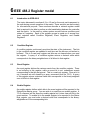
6.1
Introduction to IEEE 488.2
The topics discussed in sections 4.2 to 4.3 are for the most part transparent to
the user during normal operation of the matrix. These sections are here mainly
for informational purpose. These sections describe a minimal register model
that is required to be able to perform a safe handshaking between the controller
and the matrix. In the matrix a status system records various conditions and
states in 2 registers. Each of the register groups is made up of several lowlevel registers called Condition Registers, Event Registers, and Enable
Registers.
6.2
Condition Register
A condition register continuously monitors the state of the instrument. The bits
in the condition register are updated in real time and the bits are not latched or
buffered. This is a read-only register and bits are not cleared when you read
the register. A query of a condition register returns a decimal value which
corresponds to the binary-weighted sum of all bit set in that register.
6.3
Event Register
An event register latches the various events from the condition register. There
is no buffering in this register; while an event bit is set, subsequent events
corresponding to that bit are ignored. This is a read-only register. Once a bit is
set, it remains set until cleared by a query command (such as *CLS). A query
of this register returns a decimal value that corresponds to the binary-weighted
sum of all bits in that register.
6.4
Enable Register
An enable register defines which bits in the event register will be reported to the
Status Byte resister group. You can write to or read from an enable register. A
*CLS command will not clear the enable register but it does clear all bits in the
event resister. To enable bit in the enable register to be reported to the Statue
Byte register, you must write a decimal value that corresponds to the binaryweighted sum of the corresponding bits.
30
IEEE 488.2 Register Model
6.5
The Status Byte Register
The Status Byte register reports conditions from the other registers. Data in the
instruments output buffer is immediately reported on the “Message Available”
bit (bit 4). Clearing an event register from one of the other registers will clear
the corresponding bits in the Status Byte condition register. Reading all
messages from the output buffer, including any pending queries, will clear the
“Message Available” bit. To set the enable register mask and generate an SRQ
(service request), you must write a decimal value to the register using the *SRE
command.
Table 6-1
Bit definitions – Status Byte Register
Bit Number
Decimal Value
0
1
1
2
2
4
3
8
4 Message Available
16
5 Standard Event
32
6 Master Summary
64
7
128
Definitions
Free for manufacturer to
assign
Free for manufacturer to
assign
Free for manufacturer to
assign
Free for manufacturer to
assign
Data is available in the
instruments output buffer
One or more bits are set in
the Standard Event Register
(bits must be enabled)
One or more bits are set in
the Status Byte Register
(bits must be enabled)
Free for manufacturer to
assign
The Status Byte condition register is cleared when:
The *CLS command is executed.
One of the event registers in the other registers are read (only the
corresponding bits are cleared in the Statue Byte condition register).
The Status Byte enable register is cleared when:
The *SRE 0 command is executed.
31
IEEE 488.2 Register Model
6.6
The Standard Event Register
The Standard Event Register reports different types of events that may occur in
the instrument. Any or all of these conditions can be reported to the Standard
Event summary bit through the enable register. To set the enable register
mask, you must write a decimal value to the register using the *ESE command.
Table 6-2
Bit definitions – Standard Event Register
Bit Number
Decimal Value
0 Operation Complete
1
1
2
2 Query Error
4
3 Device Error
8
4 Execution Error
16
5 Command Error
32
6
64
7
128
Definitions
All commands prior to and
including *OPC have been
executed.
Free for manufacturer to
assign
The instrument tried to read
the output buffer but it was
empty. Or a new command
line was received before a
previous query has been
read. Or both the input and
output buffers are full.
A self-test or calibration
error occurred.
An execution error occurred.
A command syntax error
occurred.
Free for manufacturer to
assign
Free for manufacturer to
assign
The Standard event register is cleared when:
The *CLS command is executed.
A query of the event register using the *ESR? Command.
The Standard Event enable register is cleared when:
The *ESE 0 command is executed.
32
IEEE 488.2 Register Model
6.7
IEEE 488.2 Common Commands
This matrix implements common commands that the IEEE-488.2 standard
defines. The following contains a list of a subset of these commands. For more
details refer to the related section.
Table 6-3
Common Commands
Mnemonic
Name
Section
*CLS
Clear Status Command
7.4.1
*ESE
Standard Event Status Enable Command
7.4.2
*ESE?
Standard Event Status Enable Query
7.4.3
*ESR?
Standard Event Status Register Query
7.4.4
*IDN?
Identification Query
7.4.5
*OPC
Operation Complete Command
7.4.6
*OPC?
Operation Complete Query
7.4.7
*RST
Reset Command
7.4.8
*STB?
Read Status Byte Query
7.4.9
*SRE
Service Request Enable Command
7.4.10
*SRE?
Service Request Enable Query
7.4.11
*WAI
Wait-to-Continue Command
7.4.12
33
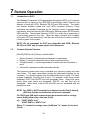
7 Remote Operation
7.1
Introduction to SCPI
The Standard Commands for Programmable Instruments (SCPI) is a command
structure that is based on the IEEE-488.2 specification which Dow-key has
adapted to work with GPIB, Ethernet, RS-232 and USB controls. The matrix
has internal software loaded that uses SCPI command structure. These
commands are standard messages for the (remote) control of programmable
instruments, which are sent by the GPIB and/or Ethernet and/or RS-232 and/or
USB controller. The principal objective of SCPI is to make the programming of
a test system easier for the user. When the basic concepts and command
structure of SCPI are understood, it will be easy for the user to write or modify a
control program for the matrix.
NOTE: Not all commands for SCPI are compatible with GPIB, Ethernet,
RS-232 and USB, only the ones stated in this document.
7.2
Command Syntax Structure
[ROUTe]:SWITch<id>[:VALue] <number>|MAX
Square brackets [ ] indicate optional keywords or parameters.
Braces { } enclosure parameter choices with a command string
Triangle brackets < > enclose parameters for which you must substitute a
value.
Vertical bar | separates multiple parameter choices.
The command syntax shows most commands as a mixture of upper and lower
case letters. The upper case letters indicate the abbreviated spelling for the
command. For shorter program lines, the abbreviated form is used. For better
program readability, the long form is used. For example, in the above syntax
statement, ROUT and ROUTE are both acceptable forms. Since both upper
and/or lower case letters are acceptable, ROUTE, rout and Rout are all
acceptable. Other forms, such as RO and ROU are not acceptable and will
generate an error.
NOTE: For GPIB no ASCII termination is required, but the End Or Identify
(EOI) line shall be asserted at the end of each command.
For RS232 and USB each command must be terminated with a carriage
return (0×0D) followed by a line feed (0×0A).
e.g. ”ROUT:SWITx n\r\n”
“ ROUT:SWITx n; SWITx?\r\n”
Where “\r” stands for carriage return (0×0D) and “\n” stands for line feed
(0×0A).
34
Remote Operation
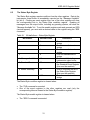
7.3
Command Separators and conventions
A colon (:) is used to separate a command keyword from a lower level
keyword.
A blank space is used to separate a parameter from a command keyword.
A comma (,) is used if a command requires more than one parameter.
A semicolon (;) is used to combine multiple commands into one message
string. Commands from the same subsystem are permitted to skip repeating
the upper-level keyword.
Eg. “Route:Switch1 8; Switch2 5; Switch3 2”
A colon is used when linking commands from different subsystems into one
message string, allowing a new upper-level keyword to be introduced. Since
the keyword is optional, such keyword could also be omitted (see example
2).
Only the first command requires the colon. Any subsequent commands of
the same subsystem do not require the colon (see example 3).
Ex. 1: “Route:Switch1 8; Switch2 5; Switch3 2; System:Error?”
Ex. 2: “Route:Switch1 8; Switch2 5; Switch3 2; :Error?”
Ex. 3: “Route:Switch1 8; Switch2 5; Switch3 2; :Error?; Timeout 2; status?”
When linking multiple commands the maximum number of transmitted
commands to the matrix in one message string is 8.
When reading responses from the matrix, the maximum number of
characters that can be received (read) is 100 characters.
Commands related to the GPIB controller’s registers can NOT be
concatenated. These commands are *ESE, *ESE?, *ESR?, *STB?, *SRE,
*SRE?.
All messages are in ASCII format (numeric values are represented in
decimal format with exception of the MAC address which is expressed in
hex format).
Timing, sequences and action requirements are only shown where
applicable and are under the TIMING sub-paragraphs on each command
description.
For RS232 and USB communication: Any string returned by the matrix is
terminated with a carriage return (0×0D) followed by a line feed (0×0A).
e.g. ”ROUT:SWIT2?\r\n”
will return
“1\r\n”
Where “\r” stands for carriage return (0×0D) and “\n” stands for line
feed (0×0A).
For GPIB communication no ASCII termination is required, but the End Or
Identify (EOI) line shall be asserted at the end of each command.
35
Remote Operation
7.4
Common Commands
The following contains the IEEE 488.2 common commands of SCPI that the
GPIB controller is compatible with.
The possible error codes assume that the correct syntax is used and, in case of
a multiple command string the string is not too long.
If these conditions are not met, any given command can generate these error
codes: 3, 4, 30
7.4.1
*CLS
Syntax
*CLS
Description
This command is used to clear the event register in all register groups.
7.4.2
*ESE
Syntax
*ESE <value>
Parameters
value Decimal value which corresponds to the binary-weighted sum of the bits
you wish to enable in the register.
Description
Enable bits in the Standard Event Status enable register.
The selected bits are then reported to the Status Byte register.
To enable bits in the Standard Event Status enable register, you must write a
decimal value that corresponds to the binary-weighted sum of the bits you wish
to enable in the register.
Note: This command can NOT be concatenated with other commands. It must
be issued as a single command.
36
Common Commands
7.4.3
*ESE?
Syntax
*ESE?
Description
This query allows the user to determine the current contents of Standard Event
Status enable register.
The value returned corresponds to the binary-weighted sum of all bits enabled
by the *ESE command.
Note: This command can NOT be concatenated with other commands. It must
be issued as a single command.
7.4.4
*ESR?
Syntax
*ESR?
Description
This query allows the user to determine the current contents of Event Status
register. Reading the Event Status Register clears it.
The status is returned as a decimal value which corresponds to the binaryweighted sum of all bits set in the register.
Note: This command can NOT be concatenated with other commands. It must
be issued as a single command.
37
Common Commands
7.4.5
*IDN?
Syntax
*IDN?
Result
A string is returned which consists of the following parts:
Model
Model
Matrix model number
Possible error codes
None
Example
“*IDN?”
Result
“MS-1U18S-10/2-GPIB”
7.4.6
*OPC
Syntax
*OPC
Description
This command causes the device to set the Operation Complete bit in the
Standard Event Register when all pending operations have been finished.
38
Common Commands
7.4.7
*OPC?
Syntax
*OPC?
Description
This query returns an ASCII character “1” when all pending operations have
been finished.
Result
ASCII character “1”.
Possible error codes
None
Example 1
*OPC?
Result
“1”
Example 2
:SWIT1 4; SWIT2 4; *OPC?
Result
“0”
Timing
In Example 2 the matrix did not have the time to execute the command. Hence
a “0” is returned. A subsequent *OPC? will return a “1” as shown in Example 1.
The timing to execute a command depends on the length of the command (in
case of concatenated commands). In case of switching commands like on
Example 2, the controller will first command each switch to set its new position,
then query each switch to ensure that the positions are closed and finally
respond with a “1” to the *OPC? query.
As a rule of thumb electromechanical switches require approximately 10-15ms
to switch position. But the *OPC? query will return a “1” only after the switches
have not only changed its positions, but rather also confirmed its position. So it
is safe to consider some safety margin and expect a response of “1” after about
70ms per switch. As an example, if 2 switches are commanded wait about
140ms before issuing an *OPC? query that will return a “1”.
39
Common Commands
7.4.8
*RST
Syntax
*RST
Description
This command performs a device reset.
This will set the instrument so that all switches are in the default state.
For SPnT switches the default state is: all RF ports are open (position 0).
For a transfer switch the default state is: position 1 is closed.
Possible error codes
11, 12, 13
Timing
Before issuing any other command after a *RST use the following
considerations.
The *RST command is ‘translated’ by the internal controller board to command,
on the CAN bus level, each switch to position 0 (open). The amount of these
commands depends on the amount of switches present in the matrix.
Each switch requires approximately 10-15ms to switch position. So to execute
an *RST command (to open all positions without verifying the switch’s positions)
will require at least n x (10 - 15ms), where n is the number of switches in the
matrix.
7.4.9
*STB?
Syntax
*STB?
Description
Query the Status Byte Register
This command is similar to a Serial Poll but is processed like any other
instrument command. This command returns the same result as a Serial Poll
but the Master Summary bit is not cleared if a Serial Poll has occurred.
Result
STB
decimal value which corresponds to the binary-weighted sum of all bits
set in the register.
Note: This command can NOT be concatenated with other commands. It must
be issued as a single command.
40
Common Commands
7.4.10
*SRE
Syntax
*SRE <enable_value>
Parameters
Enable_value
Value that corresponds to the binary-weighted sum of the bits
you wish to enable in the register.
Description
Enable bits in the Status Byte enable register.
To enable bits in the Status Byte enable register, you must write a decimal
value that corresponds to the binary-weighted sum of the bits you wish to
enable in the register.
Note: This command can NOT be concatenated with other commands. It must
be issued as a single command.
7.4.11
*SRE?
Syntax
*SRE?
Description
The *SRE? query returns a decimal value which corresponds to the binaryweighted sum of all bits enabled by the *SRE command.
Result
Returns a decimal value which corresponds to the binary-weighted sum of all
bits enabled by the *SRE command.
Example
“*SRE?”
Result was “16”
Note: This command can NOT be concatenated with other commands. It must
be issued as a single command.
7.4.12
*WAI
Syntax
*WAI
Description
This command prevents the instrument from executing any further commands
or queries until the current commands have been processed by the parser.
41
Remote Operation
7.5
System Commands
The following contains the SCPI system commands that the GPIB, RS-232 and
USB control is compatible with.
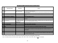
7.5.1
SYST:ERR?
Syntax
SYSTem:ERRor?
Description
Query the instrument’s error queue. A record of up to N errors is stored in the
instrument’s error queue. Errors are retrieved in first-in first-out (FIFO) order.
The first error returned is the first error that was stored. Each additional error
up to N is read by N subsequent queries (one for each error). For this
instrument N=20. The error queue has to be read until no more errors are
returned, otherwise the error status is not cleared.
Note: Some of the listed error codes are here for backwards compatibility with
legacy products and other are reserved for future applications. Not all error
codes are applicable to this matrix.
Result
String with the following syntax:
code, message
code: Numeric value with the error code (0 if no error).
Message: String with error message.
42
Remote Operation
Example
“SYST:ERR?”
Result was “1, INVALID CHARACTER”, check for more errors.
Description: This error is no longer supported. The error code is
maintained and reserved for legacy purposes only.
“SYST:ERR?”
Result was “2, OUTPUT BUFFER OVERFLOW”, check for more errors.
Description: This error is no longer supported. The error code is
maintained and reserved for legacy purposes only.
“SYST:ERR?”
Result was “3, TOO MANY COMMANDS”, check for more errors.
Description: The maximum of 220 characters per command line has been
exceeded.
SYST:ERR?”
Result was “4, SYNTAX ERROR”, check for more errors.
Description: There is a misspelling in your command or a non-numeric
character was included in a command where a number should have been, or
use of unrecognized symbols such as %, &, #, etc.
SYST:ERR?”
Result was “5, DATA OUT OF RANGE”, check for more errors.
Description: The value transmitted is not acceptable.
Eg. 1: A non existing switch positions has been commanded. Sending
Route:Switch1 8. When switch 1 is a SP6T (6 position switch)
Eg. 2: This error code is set if the IP address or MAC address is an invalid
one. Sending SYSTEM:IPADDRESS 55.57.2 would generate this error
code since 4 numbers are required for a valid IP address.
SYST:ERR?”
Result was “6, ILLEGAL PARAMETER VALUE”, check for more errors.
Description: This error is no longer supported. The error code is
maintained and reserved for legacy purposes only.
SYST:ERR?”
Result was “7, INPUT BUFFER UNDERFLOW”, check for more errors.
Description: This error is no longer supported. The error code is
maintained and reserved for legacy purposes only.
SYST:ERR?”
Result was “8, MATRIX SOCKET NOT AVAIL”, check for more errors.
Description: This error is no longer supported. The error code is
maintained and reserved for legacy purposes only.
43
Remote Operation
SYST:ERR?”
Result was “10, SWITCH DID NOT RESPOND,x”, check for more errors.
Description: Switch x did not respond to a position query.
E.g. CAN bus communication failure or damaged switch.
SYST:ERR?”
Result was “11, SWITCH’S RESPONSE INVALID,x”, check for more errors.
Description: Switch x responded but with the wrong response code. This
error is related to wrong internal CAN bus communication codes.
SYST:ERR?”
Result was “12, SWITCH’S POSITION INCORRECT,x”, check for more errors.
Description: Switch x reported to be closed on a position different than
what it was commanded to be.
E.g. Commanded position is 4, reported position is 3.
SYST:ERR?”
Result was “13, SWITCH’S POSITION UNKNOWN,x”, check for more errors.
Description: Switch x reported to be closed on an unknown position. E.g.
A defective / damaged switch.
SYST:ERR?”
Result was “20, MATRIX IS NOT CONFIGURED”, check for more errors.
Description: The configuration file (factory configuration) defining all
switches configured inside the matrix has not been uploaded. The matrix
does not ‘know’ what and how many switches to control.
SYST:ERR?”
Result was “21, CONFIGURATION FILE IS CORRUPT”, check for more errors.
Description: The configuration file (factory configuration) defining all
switches configured inside the matrix is corrupted.
SYST:ERR?”
Result was “22, CONFIGURATION FILE DOES NOT MATCH INSTALLED
SWITCHES”, check for more errors.
Description: The configuration file (factory configuration), which defines all
switches configured inside the matrix, does not match the actual installed
switch types.
This error code is generated only at boot up and refers only to answering
switches. A switch not answering to CAN messages would result into an
error code 10.
SYST:ERR?”
Result was “23, MATRIX CONTAINS A 0 ID”, check for more errors.
Description: The matrix contains a switch that has not been assigned a
valid CAN bus address. ID 0 is not a valid CAN bus address.
44
Remote Operation
SYST:ERR?”
Result was “30, COMMAND UNRECOGNIZED”, check for more errors.
Description: This error code is generated when the commanded string
does not contain any valid keyword (e.g. Route, System, *IDN?, *RST,
….) at all.
SYST:ERR?”
Result was “36, ID IS OUT OF RANGE”, check for more errors.
Description: A non existing switch ID has been commanded.
Eg. Sending Route:Switch11 8. When switch 11 does not exist.
SYST:ERR?”
Result was “50, UNABLE TO AQUIRE IP ADDRESS”, check for more errors.
Description: DHCP is enabled (ON), but the IP address could not be
acquired dynamically.
Eg. Ethernet connection cable is disconnected.
SYST:ERR?”
Result was “51, FAN STALL”, check for more errors.
Description: On models with fans equipped with sensors, one or more fans
have stalled (only when this alarm has been enabled at the factory).
Note: Not applicable for most models.
SYST:ERR?”
Result was “52, INTERNAL TEMPERATURE EXCEEDS THERSHOLD”, check
for more errors.
Description: On models with temperature sensors, one or more
temperature sensors has exceeded its alarm threshold (only when this
alarm has been enabled at the factory).
Note: Not applicable for most models.
SYST:ERR?”
Result was “53, POWER SUPPLY FAILURE”, check for more errors.
Description: On matrices with redundant power supplies it will indicate that
one of the power supplies does not operate.
E.g. Damaged power supply or blown fuse on the power supply.
Result was “0”NO ERROR””, No more errors, error queue is empty.
45
Remote Operation
7.5.2
SYST:SERIALNUMBER?
Syntax
SYSTem:SERIALNUMBER?
Description
Returns the matrix serial number.
Result
n
Possible error codes
None
46
Remote Operation
7.5.3
SYST:STATUS?
Syntax
SYSTem:STATUS?
Description
This command will return all Switch positions, Local/Remote mode, Power
supply status, High temperature alarm status, Fan stall alarm and Errors list
separated by a semicolon. The status response will reflect ALL items in the
matrix, while the error portion of the response is limited to the first 20 errors.
Note 1: Power supply status, High temperature alarm status and Fan stall alarm
are only returned if enabled.
(Most models do not have redundant power supplies, temperature sensors and
fans and therefore will not report this status information)
Note 2: Multiple instances of the same error code will appear multiple times.
E.g. if two different switches fail to respond to CAN messages, two instances of
error 10 will be returned.
But multiple error instances of the same switch will appear only once.
Result
“SWITx y;SWITx y;SWITx y;…….;SWITx y;LOC;PWR1 OK;PWR2 FAULT;
ERRORS 5,3;0”
SWIT
= Switch
X
= Switch number (ID)
Y
= Switch position
LOC
= Local mode
REM
= Remote mode
PWR1
= Power supply 1
PWR2
= Power supply 2 (Only for systems with dual power supplies)
TEMP1
= Temperature sensor 1 (Only if temp sensor 1 is enabled)
TEMP2
= Temperature sensor 2 (Only if temp sensor 2 is enabled)
TEMP3
= Temperature sensor 3 (Only if temp sensor 3 is enabled)
TEMP4
= Temperature sensor 4 (Only if temp sensor 4 is enabled)
FAN1
= Fan 1 (Only if Fan sensor 1 is enabled)
FAN2
= Fan 2 (Only if Fan sensor 2 is enabled)
FAN3
= Fan 3 (Only if Fan sensor 3 is enabled)
FAN4
= Fan 4 (Only if Fan sensor 4 is enabled)
ERRORS = Error codes (Each number corresponds to a specific error code
described in the user manual. Not all error codes apply to the matrix).
Possible error codes
None
47
Remote Operation
7.5.4
SYST:SCREENSAVER?
Syntax
SYSTem:SCREENSAVER?
Description
This command will return the screen saver time settings n (n is in minutes).
Possible values for n are 0, 2, 3, 4, 5, ……
Note that 1 is not a valid value.
0 = Screen saver is disabled
Possible error codes
5
Factory default value
5
Power on behavior
Keeps last value
*RST effect
None
7.5.5
SYST:SCREENSAVER x
Syntax
SYSTem:SCREENSAVER x
Description
This command will set the screen saver time settings x (x is in minutes).
Possible values for x are 0, 2, 3, 4, 5, ……
Note that 1 is not a valid value.
0 = Screen saver is disabled
Possible error codes
5
Factory default value
5
Power on behavior
Keeps last value
*RST effect
None
48
Remote Operation
7.5.6
SYST:GPIBADDRESS?
Syntax
SYSTem:GPIBADDRESS?
Description
This command will return the matrix’s GPIB address.
Possible values are 1 to 30
Possible error codes
5
Factory default value
9
Power on behavior
Keeps last value
*RST effect
None
7.5.7
SYST:GPIBADDRESS x
Syntax
SYSTem:GPIBADDRESS x
Description
This command will set the GPIB address to x.
Possible values for x are 1 to 30.
Possible error codes
5
Factory default value
9
Power on behavior
Keeps last value
*RST effect
None
49
Remote Operation
7.6
Switch [Module] Command Set
The following contains the switch [module] commands of SCPI that the GPIB /
RS 232 / USB control is compatible with.
7.6.1
:SWITch<id>[:VALue] <number>
Syntax
[ROUTe]:SWITch<id>[:VALue] <number>
Description
This command is used to control the position of the switches. The switch
specified by the numeric suffix <id> is set to position <number>. Switch
positions are specified in a 0 to N fashion, therefore legal values for <number>
are from 0 to the maximum number of position for the switch. For example, a
SP10T switch has 11 positions, 0 thru 10. Position 0 means the switch is set to
its default position.
For most switches the default position is pos 0 (open switch). So in case of a
SP10T switch this means no position is closed.
In case of a transfer switch, since it does not have an open position, the default
position is pos 1. So commanding it to pos 0 will close it to position 1.
50
Remote Operation
7.6.2
Setting switch x to position n
x = switch [module] address.
n = position to set and must be within the switches parameter.
(Example: SP10T valid positions are 0 thru 10 only).
Examples:
ROUTE:SWITCHx n
ROUT:SWITCHx n
ROUTE:SWITx n
ROUT:SWITx n
:SWITCHx n
:SWITx n
ROUTE:SWITCHx:VALUE n
ROUTE:SWITCHx:VAL n
:SWITx:VAL n
Possible error codes
5, 10, 12, 13
Factory default value
N.a.
Power on behavior
Keeps last value
*RST effect
SP6T switch: will open all positions
Transfer switch: will close position 1
Timing
The timing to execute a command depends on the length of the command (in
case of concatenated commands). In case of switching commands the
controller will first command each switch to set its new position, then query
each switch to ensure that the positions are closed. Only after this internal
verification (that happens automatically) the controller will respond with a “1” to
the *OPC? query and update the error status.
As a rule of thumb electromechanical switches require approximately 10-15ms
to switch position.
But the *OPC? query will return a “1” or the error status is updated only after the
switches have not only changed its positions, but rather also confirmed its
position. So it is safe to consider some safety margin and expect a response of
“1” or an updated error status after about 70ms per switch.
As an example if 2 switches are commanded, wait about 140ms before issuing
an *OPC? query that will return a “1” or issuing an SYST:ERR? query or issuing
a ROUTE:SWITCHx? query.
51
Remote Operation
7.6.3
Requesting Switch x current position
x = switch address.
Examples:
ROUTE:SWITCHx?
ROUT:SWITx?
:SWITx?
Result:
Returns the current position of switch x.
Possible error codes
10, 11, 12, 13
Timing
The timing to execute a command depends on the length of the command (in
case of concatenated commands). In case of switching commands the
controller will first command each switch to set its new position and then query
each switch to ensure that the positions are closed. Only after this internal
verification (that happens automatically) will the controller respond with a “1” to
the *OPC? query and update the error status.
As a rule of thumb electromechanical switches require approximately 10-15ms
to switch position.
But the *OPC? query will return a “1” or the error status will be updated only
after the switches have changed and confirmed their positions. So it is safe to
consider some safety margin and expect a response of “1” or an updated error
status after about 70ms per switch.
As an example if 2 switches are commanded, wait about 140ms before issuing
an *OPC? query that will return a “1” or issuing an SYST:ERR? query or issuing
a ROUTE:SWITCHx? query.
52
Remote Operation
This page intentionally left blank
53
GPIB, RS232 and USB Command description for standard matrices
Command Syntax
Response
1
*IDN?
MS-1U18S-1/6-GPIB
2
*OPC?
1 or 0
3
*RST
4
5
18
ROUTE:SWITCHx y or :SWITCHx y
ROUTE:SWITCHx? or :SWITCHx?
SYST:SERIALNUMBER?
n
n
22
SYST:ERR? or SYST:ERROR?
-4,SYNTAX ERROR
23
SYST:STATUS?
24
25
26
27
31
32
33
34
SYST:SCREENSAVER?
SYST:SCREENSAVER x
SYST:GPIBADDRESS?
SYST:GPIBADDRESS x
*CLS
*ESE
*ESE?
*ESR?
35
*OPC
36
37
38
*STB?
*SRE
*SRE?
39
*WAI
SWITx y;SWITx y;SWITx
y;… ;SWITx y;LOC;PWR1
OK;PWR2 FAULT;
ERRORS 5,3;0
n
9
Action
Returns string in ’Model Name’ in the configuration file.
As a minimum will have model name.
Could also have: Vendor, model, serial number, firmware revision (The response shown in this table
is just an example).
Gives 1 if previous operation was completed and gives 0 if previous operation is still not complete.
Puts all switches in the default position. (Transfer switches in pos.1. Most other switches in pos. 0 =
open).
Closes position y on switch x
Gives current position of switch x
Returns system serial number
Returns system error number and error description. (The response shown in this table is just an
example).
This command will return all Switch positions, Local/Remote mode, Power supply status and Errors
list in the error buffer separated by a semicolon.
Returns time setting for the screen saver (n is in minutes)
Sets time setting for the screen saver (x is in minutes)
Returns matrix system’s GPIB address
Sets matrix system’s GPIB address to x
Clear Status Command used to clear the Event Register in all register groups.
Command used to enable bits in the Standard Event Status Enable register.
Query used to read the content of the Standard Event Status Enable register.
Query used to read the content of the Event Status Register.
Sets the Operation Complete bit in the Event Status Register when all pending operations have
been finished.
Query used to read the content of the Status Byte Register.
Command used to enable bits in the Service Request Enable register.
Query used to read the content of the Service Request Enable register.
This command prevents the matrix from executing any further commands or queries until the current
commands have been processed.
Note 1: Missing command numbers are commands reserved for Ethernet matrices and not applicable to GPIB models.
Note 2: Commands related to the GPIB controller’s registers *ESE, *ESE?, *ESR?, *STB?, *SRE, *SRE? can NOT be concatenated.
54
Remote Operation
Note:
1. Commands are NOT case sensitive.
2. For GPIB communication no ASCII termination is required, but the End Or Identify (EOI) line
shall be asserted at the end of each command.
3. Every command and response on the serial or USB port shall have “\r\n” Carriage return
(0x0D) and Line Feed (0x0A) at the end.
4. Multiple commands with same header can be given in a single command line. (See rule # 5
for an exception to this).
e.g. SYST:IPADDRESS?;TCPPORT?;SERIALNUMBER 2 or ROUTE:SWITCH1
2;SWITCH1?;
note that the commands have to separated by ‘;’
5. Exception to rule # 4 are commands related to the GPIB controller’s registers *ESE, *ESE?,
*ESR?, *STB?, *SRE, *SRE?. These commands can NOT be concatenated.
6. The default GPIB address is: 9
7. In command SYST: SCREENSAVER? and SYST:SCREENSAVER x, the value n and x is in
minutes. The default value is 5 (minutes). 0 = no screen saver. Valid values for x are: 0, 2, 3,
4, 5, 6,….
55
Appendix A
Technical Specifications
Model:
MS-1U18S-1/6-GPIB
Configuration:
1 normally open SP6T switch mounted on the rear
panel
RF Connectors:
SMA (on rear panel)
Frequency range:
DC to 18 GHz
Return loss (VSWR)
Insertion loss
Isolation
RF Power:
Frequency (GHz): VSWR (Ratio max): Insertion Loss (dB max): Isolation (dB min): RF Power (Watts CW max): DC ‐ 3 3 ‐ 8 8 – 12.4 12.4 ‐ 18 1.20 : 1 1.30 : 1 1.40 : 1 1.50 : 1 0.2 0.3 0.4 0.5 80 70 60 60 125 90 75 60 Impedance:
50 Ω
Switching Speed:
50ms (per switch)
Operating Temp:
0 to 50 degrees C
Switch Type:
One normally open SP6T
Switch p.n. 565-5208-3-ROHS
Line Voltage:
120-240 VAC, 50-60 Hz
Control Interfaces:
GPIB (IEEE 488) Connector
RS-232 via 9-pin D-Sub female connector
CAN Bus via 4 pin XLR female connector
USB type A (used as ‘virtual’ serial port)
RS-232 Settings:
Settable at 1200, 2400, 4800, 9600 (default),
19200, 38400, 57600,115200 bits/sec,
8 bit data, no parity, 1 stop bit
Dimensions:
1.72” H x 19” W x 14.75” D (without handles)
56
Appendix B
RF Configuration
Model: MS-1U18S-1/6-GPIB
One normally open SP6T switch (Dow-Key part number: 565-5208-3-ROHS)
mounted on the rear.
Matrix RF diagram
Note: The switch is bi-directional. Hence each RF port can be considered an input
or an output.
57