1
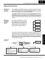
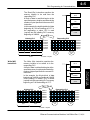
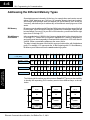
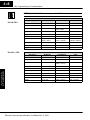
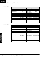
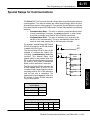
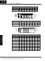
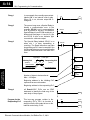
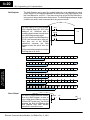
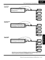
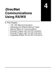
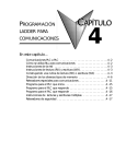
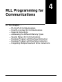
1
RLL Programming for
Communications
4
In This Chapter. . . .
— PLC-to-PLC Communications
— How RLL is Used for Communications
— Network Instructions
— Addressing the Different Memory Types
— Special Relays for Communications
— Example Program with One Read Instruction
— Example Program with One Write Instruction
— Integrating Multiple Read and Write Instructions
4--2
RLL Programming for Communications
Getting Started
PLC-to-PLC Communications
This chapter steps you through the development of a Relay Ladder Logic (RLL)
program to enable one PLC to communicate with another PLC. For the experienced
programmer of DirectLOGIC PLCs, the communication programs presented in this
chapter will be simple to follow. If you have never programmed a DirectLOGIC PLC,
you may want to refer to the DirectSOFT Programming Software User Manual and
the User Manual for your PLC for additional information.
NOTE: The programs described in this chapter are not used for communication
between a PC and a PLC. For PC-to-PLC communications, please see the product
documentation for the PC software you are using. If you are using our DSData
Server software, the manual you will need is the KEPDirect for PLCs User Manual.
How RLL is Used for Communications
User Application
Guidelines
DirectSOFT Programming Software provides Read and Write instructions
(RX/WX) for PLC-to-PLC communication over a network. The Read and Write
instructions are part of the ladder logic program running in the CPU of the initiating,
or master, PLC. These instructions tell the initiating CPU to send a message over the
Ethernet network to a responding, or slave, PLC. The ECOM module is the
connecting point to the network for each PLC. The initiating PLC’s Read or Write
communication finds its destination by the Module ID of the responding PLC’s
ECOM module. See Chapter 2 and 3 for information about assigning Module IDs.
RLL Programming
for Communications
Module ID 3
CPU
O
U
T
P
U
T
E I
C N
O P
M U
T
CPU
O
U
T
P
U
T
Wr i te
Re a d
Initiating PLC
CPU
I E
N C
P O
U M
T
Module ID 14
I
N
P
U
T
O
U
T
P
U
T
CPU
I E
N C
P O
U M
T
Responding PLC
Hub
O
U
T
P
U
T
Module ID 9
O
U
T
P
U
T
CPU
I
N
P
U
T
E
C
O
M
O
U
T
P
U
T
Module ID 20
In the figure above, the initiating PLC sends a Read or Write message to the
responding PLC’s ECOM module which is designated as “Module ID 14.” The
responding PLC processes the message. Any one of the PLCs could initiate
communication with any one of the others.
Ethernet Communications Modules, 3rd Edition Rev. C, 06/11
RLL Programming for Communications
4--3
Network Instructions
Read (RX) and
Write (WX)
Instructions
The Read (RX) and Write (WX) instructions are used by the initiating PLC to Read a
block of data from another PLC or Write a block of data to another PLC. To perform
their functions, the RX and WX boxes must be preceded in the ladder logic program
by two Load instructions and one Load Address instruction.
The Load and Load Address instructions load communication parameters into the
accumulator and the first and second level of the accumulator stack. The RX or
WX instruction takes these parameters from the stack and the accumulator and
prepares the data to be sent over the network. If you need to know more about the
function of the accumulator and the accumulator stack, refer to the User Manual for
your PLC.
Building the
Read (RX) or
Write (WX)
Routine
For network communications, you build
the Read (RX) or Write (WX) instructions
into a routine which requires the four
instructions you see to the right. The
function of each of these instructions is
explained below or on the next page. They
must be used in the sequence shown.
LD
A aaa
LD
A aaa
O aaa
RX or WX
A aaa
The First LD
Instruction
Upper Byte
Lower Byte
Initiating PLC
(Master)
Base Number
CPU Base = 0
Expansion Base = 1, 2 or 3
See page 2-7 and 2--9 about using ECOMs in local expansion or
in remote I/O bases.
K 0 1 1 4
Responding PLC
LD
K114
(Slave)
ECOM Slot Number
Initiating PLC
See page 2-7 and 2-8 about
slot numbers.
ECOM Module ID
Responding PLC
See page 2-3 and 3--8 about
setting the Module ID.
Ethernet Communications Modules, 3rd Edition Rev. C, 06/11
RLL Programming
for Communications
The first Load (LD) instruction accepts either a constant or a variable. Use a “K” to
designate the number as a constant. Use a “V” if you are entering the address of a
register. The contents of that register perform the same function as the constant
shown below. For example, you could use V2000 in place of K0114. If the contents of
V2000 is the number “114,” the function would be the same. Using a variable allows
changing parameters while the program is running. It is recommended, however, to
use a constant when possible.
User Application
Guidelines
LDA
Getting Started
4--4
RLL Programming for Communications
The Second LD
Instruction
The second Load (LD) instruction
determines the length of the data block to
be transmitted during the Read or Write
communication. This instruction will also
accept two data types. Use a “K” to
designate the number as a constant. Use a
“V” if you are entering the address of a
register.
For Word Memory data, you must use a
multiple of two bytes between 2 and 128.
For Bit Memory data, you can use any
multiple of one byte between 1 and 128.
For more information about addressing
Word and Bit Memory, see page 4-6.
LD
K114
LD
K8
PLC Memory
RLL Programming
for Communications
User Application
Guidelines
4 words = 8 bytes
The LDA
Instruction
The Load Address (LDA) instruction
specifies the V-memory address of the
beginning memory register in the
initiating, or master, PLC. The data block
to be transmitted will begin at this address
and extend the number of bytes specified
in the preceding LD instruction. The
leading “O” indicates this is an octal
number. Simply substitute the letter “O” for
the “V” in the V-memory designation. For
example, V40600 becomes O40600.
Read instructions copy the data block from
the responding PLC memory into the
initiating PLC memory.
Write instructions copy the data block from
the initiating PLC memory into the
responding PLC memory.
LD
K114
LD
K8
LDA
O40600
Initiating PLC
V40577
V40600
V40601
V40602
V40603
V40604
Ethernet Communications Modules, 3rd Edition Rev. C, 06/11
4--5
RLL Programming for Communications
The Read (RX) instruction specifies the
memory location to be read from the
responding PLC.
A block of data is read that begins at the
specified memory location and extends the
number of bytes specified in the second LD
instruction.
In this example, the eight byte block of data
beginning at C100 and ending at C177 in
the responding, or slave, PLC is read
(copied) into the initiating PLC’s memory
beginning at V40600.
LD
K114
LD
K8
LDA
O40600
RX
C100
Re a d
Responding PLC
Initiating PLC
V40577
V40600
V40601
V40602
V40603
V40604
word
Write (WX)
Instruction
C177
bit
byte
C100
bit
4 words = 8 bytes
The Write (WX) instruction specifies the
memory location to be written to in the
responding PLC.
A block of data is written that begins at the
specified memory location and extends the
number of bytes specified in the second LD
instruction.
In the example, the 8-byte block of data
beginning at V40600 and ending at V40603
in the initiating, or master, PLC is written
(copied) into the responding PLC’s memory
beginning at C100 and ending at C177.
LD
K114
LD
K8
O40600
WX
C100
Responding PLC
V40577
V40600
V40601
V40602
V40603
V40604
byte
C177
bit
byte
word
V40603
V40604
V40605
V40606
V40607
V40610
C100
bit
4 words = 8 bytes
Ethernet Communications Modules, 3rd Edition Rev. C, 06/11
RLL Programming
for Communications
LDA
W r i t e
Initiating PLC
User Application
Guidelines
byte
V40603
V40604
V40605
V40606
V40607
V40610
4--6
RLL Programming for Communications
Getting Started
Addressing the Different Memory Types
Bit Memory
RLL Programming
for Communications
User Application
Guidelines
Word Memory
and Aliases
Some data types are inherently 16 bits long, for example timer and counter current
values. Other data types are 1 bit long, for example: discrete inputs and outputs.
Word-length and bit-length data are mapped into Word Memory, also known as
V-memory, which allows you to address any of the different memory types as 16-bit
words.
Bit memory can be addressed in Read and Write instructions by the name of the first
bit of any byte. If your second LD instruction contains the constant K8, eight bytes will
be transmitted. If you use C0 in your RX or WX instruction, you will transmit the eight
bytes from C0 through C77.
In the example below, V40600 is the V-memory designation for the sixteen bits from
C0 through C17. Aliases are a convenient substitute for V-memory designations,
and can be used interchangeably in Read and Write instructions. VC0 is the alias for
V40600. Either nomenclature addresses the same 16 bits.
The alias is simply the name of the first bit in a group of sixteen bits, with V added as a
prefix. For example, VC0 represents the 16 bits beginning with C0. Word Memory,
Bit Memory and Aliases all use the octal numbering system.
Word Memory Address V40600
= VC0 (Alias)
C17 C16 C15 C14 C13 C12 C11 C10 C7
C6
C5
C4
C3
C2
C1
C0
V40601 = VC20
C37 C36 C35 C34 C33 C32 C31 C30 C27 C26 C25 C24 C23 C22 C21 C20
V40602 = VC40
C57 C56 C55 C54 C53 C52 C51 C50 C47 C46 C45 C44 C43 C42 C41 C40
V40603 = VC60
C77 C76 C75 C74 C73 C72 C71 C70 C67 C66 C65 C64 C63 C62 C61 C60
The following Write routines are all equivalent. DirectSOFT gives you the flexibility
to identify the responding PLC’s memory area in three different ways, as shown
below.
LD
LD
K114
LD
LD
K8
LDA
LD
K114
O40600
WX
LD
K8
LDA
O40600
WX
C100
Ethernet Communications Modules, 3rd Edition Rev. C, 06/11
K114
K8
LDA
O40600
WX
VC100
V40605
RLL Programming for Communications
DirectSOFT
is Flexible
4--7
You can address the different data types by any available convention shown in the
tables that follow. The largest block of data that can be sent in a single Read or Write
operation is 128 bytes. The smallest block of data is one byte for Bit Memory types
and two bytes, or one word for Word Memory types. The octal numbering system is
used for all addresses in these tables.
DL05 CPU
DL05 CPU
Data Types
Bit Memory
Word Memory
Alias
Timer Current Values
None
V0 -- V177
TA0 -- TA177
Counter Current Values
None
V1000 -- V1177
CTA0 -- CTA177
None
V1200 -- V7377
User Data Words
None
X0 -- X377
V40400 -- V40417
VX0 -- VX360
Output Points
(See note 1)
Y0 -- Y377
V40500 -- V40517
VY0 -- VY360
Control Relays
C0 -- C777
V40600 -- V40677
VC0 -- VC760
Special Relays
SP0 -- SP777
V41200 -- V41237
VSP0 -- VSP760
Timer Status Bits
T0 -- T177
V41100 -- V41107
VT0 -- VT160
Counter Status Bits
CT0 -- CT177
V41140 -- V41147
VCT0 -- VCT160
Stages
S0 -- S377
V41000 -- V41017
VS0 -- VS360
1 -- The DL05 systems are limited to 8 discrete inputs and 6 discrete outputs with the present available hardware, but
256 point addresses exist.
DL06 CPU
DL06 CPU
Data Types
Bit Memory
Word Memory
User Application
Guidelines
Input Points
(See note 1)
Alias
None
V0 -- V377
TA0 -- TA377
Counter Current Values
None
V1000 -- V1177
CTA0 -- CTA177
User Data Words
None
V400 -- V677
V1200 -- V7377
V10000 -- V17777
None
Input Points
(See note 1)
X0 -- X777
V40400 -- V40437
VX0 -- VX760
Output Points
(See note 1)
Y0 -- Y777
V40500 -- V40537
VY0 -- VY760
Control Relays
C0 -- C1777
V40600 -- V40677
VC0 -- VC1760
Special Relays
SP0 -- SP777
V41200 -- V41237
VSP0 -- VSP760
Timer Status Bits
T0 -- T377
V41100 -- V41117
VT0 -- VT160
Counter Status Bits
CT0 -- CT177
V41140 -- V41147
VCT0 -- VCT160
Stages
S0 -- S1777
V41000 -- V41077
VS0 -- VS1760
Remote I/O
GX0 -- GX3777
GY0 -- GY3777
V40000 -- V40177
V40200 -- V40377
VGX0 -- VGX3760
VGY0 -- VGY3760
1 -- The DL06 systems are limited to 20 discrete inputs and 16 discrete outputs with the present available hardware,
but 512 point addresses exist.
Ethernet Communications Modules, 3rd Edition Rev. C, 06/11
RLL Programming
for Communications
Timer Current Values
RLL Programming
for Communications
User Application
Guidelines
Getting Started
4--8
RLL Programming for Communications
NOTE: The D2--230 CPU does not support the ECOM modules.
D2--240 CPU
D2--240 CPU
Data Types
Bit Memory
Word Memory
Alias
Timer Current Values
None
V0 -- V177
TA0 -- TA177
Counter Current Values
None
V1000 -- V1177
CTA0 -- CTA177
User Data Words
None
V2000 -- V3777
V4000 -- V4377
None
Input Points
X0 -- X477
V40400 -- V40423
VX0 -- VX460
Output Points
Y0 -- Y477
V40500 -- V40523
VY0 -- VY460
Control Relays
C0 -- C377
V40600 -- V40617
VC0 -- VC360
Special Relays
SP0 -- SP137
SP540 -- SP617
V41200 -- V41205
V41226 -- V41230
VSP0 -- VSP120
VSP540 -- VSP600
Timer Status Bits
T0 -- T177
V41100 -- V41107
VT0 -- VT160
Counter Status Bits
CT0 -- CT177
V41040 -- V41147
VCT0 -- VCT160
Stages
S0 -- S777
V41000 -- V41037
VS0 -- VS760
D2--250--1 CPU
D2--250--1 CPU
Data Types
Bit Memory
Word Memory
Alias
Timer Current Values
None
V0 -- V377
TA0 -- TA377
Counter Current Values
None
V1000 -- V1377
CTA0 -- CTA377
User Data Words
None
V1400 -- V7377
V10000 -- V17777
None
Input Points
X0 -- X777
V40400 -- V40437
VX0 -- VX760
Output Points
Y0 -- Y777
V40500 -- V40537
VY0 -- VY760
Control Relays
C0 -- C1777
V40600 -- V40677
VC0 -- VC1760
Special Relays
SP0 -- SP777
V41200 -- V41237
VSP0 -- VSP760
Timer Status Bits
T0 -- T377
V41100 -- V41117
VT0 -- VT360
Counter Status Bits
CT0 -- CT177
V41140 -- V41147
VCT0 -- VCT160
Stages
S0 -- S1777
V41000 -- V41077
VS0 -- VS1760
Ethernet Communications Modules, 3rd Edition Rev. C, 06/11
RLL Programming for Communications
D2--260 CPU
4--9
D2--260 CPU
Data Registers
Bit Memory
Word Memory
Alias
Timer Current Values
None
V0 -- V377
TA0 -- TA377
Counter Current Values
None
V1000 -- V1377
CTA0 -- CTA377
User Data Words
None
V400 -- V777
V1400 -- V7377
V10000 -- V37777
None
Input Points
X0 -- X1777
V40400 -- V40477
VX0 -- VX1760
Output Points
Y0 -- Y1777
V40500 -- V40577
VY0 -- VY1760
Control Relays
C0 -- C3777
V40600 -- V40777
VC0 -- VC3760
Special Relays
SP0 -- SP137
SP320 -- SP717
V41200 -- V41205
V41215 -- V41234
VSP0 -- VSP120
VSP320 -- VSP700
Timer Status Bits
T0 -- T377
V41100 -- V41117
VT0 -- VT360
Counter Status Bits
CT0 -- CT377
V41140 -- V41157
VCT0 -- VCT360
Stages
S0 -- S1777
V41000 -- V41077
VS0 -- VS1760
Remote I/O
GX0 -- GX3777
GY0 -- GY3777
V40000 -- V40177
V40200 -- V40377
VGX0 -- VGX3760
VGY0 -- VGY3760
D4--430 CPU
Data Registers
Bit Memory
Word Memory
Alias
Timer Current Values
None
V0 -- V177
TA0 -- TA177
Counter Current Values
None
V1000 -- V1177
CTA0 -- CTA177
User Data Words
None
V1400 -- V7377
None
X0 -- X477
V40400 -- V40423
VX0 -- VX460
Output Points
Y0 -- Y477
V40500 -- V40523
VY0 -- VY460
Control Relays
C0 -- C737
V40600 -- V40635
VC0 -- VC720
Special Relays
SP0 -- 137
SP320 -- SP617
V41200 -- V41205
V41215 -- V41230
VSP0 -- VSP120
VSP320 -- VSP600
Timer Status Bits
T0 -- T177
V41100 -- V41107
VT0 -- VT160
Counter Status Bits
CT0 -- CT177
V41140 -- V41147
VCT0 -- VCT160
Stages
S0 -- S577
V41000 -- V41027
VS0 -- VS560
Remote I/O
GX0 -- GX777
V40000 -- V40037
VGX0 -- VGX760
Ethernet Communications Modules, 3rd Edition Rev. C, 06/11
RLL Programming
for Communications
Input Points
User Application
Guidelines
D4--430 CPU
Getting Started
4--10
RLL Programming for Communications
D4--440 CPU
D4--440 CPU
Data Registers
Bit Memory
User Application
Guidelines
Alias
Timer Current Values
None
V0 -- V377
TA0 -- TA377
Counter Current Values
None
V1000 -- V1177
CTA0 -- CTA177
User Data Words
None
V1400 -- V7377
V10000 -- V17777
None
Input Points
X0 -- X477
V40400 -- V40423
VX0 -- VX460
Output Points
Y0 -- Y477
V40500 -- V40523
VY0 -- VY460
Control Relays
C0 -- C1777
V40600 -- V40677
VC0 -- VC1760
Special Relays
SP0 -- 137
SP320 -- SP717
V41200 -- V41205
V41215 -- V41234
VSP0 -- VSP120
VSP320 -- VSP700
Timer Status Bits
T0 -- T377
V41100 -- V41117
VT0 -- VT360
Counter Status Bits
CT0 -- CT177
V41140 -- V41147
VCT0 -- VCT160
Stages
S0 -- S1777
V41000 -- V41077
VS0 -- VS1760
Remote I/O
GX0 -- GX1777
V40000 -- V40077
VGX0 -- VGX1760
D4--450 CPU
RLL Programming
for Communications
Word Memory
D4--450 CPU
Data Registers
Bit Memory
Word Memory
Alias
Timer Current Values
None
V0 -- V377
TA0 -- TA377
Counter Current Values
None
V1000 -- V1377
CTA0 -- CTA377
User Data Words
None
V1400 -- V7377
V10000 -- V37777
None
Input Points
X0 -- X1777
V40400 -- V40477
VX0 -- VX1760
Output Points
Y0 -- Y1777
V40500 -- V40577
VY0 -- VY1760
Control Relays
C0 -- C3777
V40600 -- V40777
VC0 -- VC3760
Special Relays
SP0 -- SP137
SP320 -- SP717
V41200 -- V41205
V41215 -- V41234
VSP0 -- VSP120
VSP320 -- VSP700
Timer Status Bits
T0 -- T377
V41100 -- V41117
VT0 -- VT360
Counter Status Bits
CT0 -- CT377
V41140 -- V41157
VCT0 -- VCT360
Stages
S0 -- S1777
V41000 -- V41077
VS0 -- VS1760
Remote I/O
GX0 -- GX3777
GY0 -- GY3777
V40000 -- V40177
V40200 -- V40377
VGX0 -- VGX3760
VGY0 -- VGY3760
Ethernet Communications Modules, 3rd Edition Rev. C, 06/11
RLL Programming for Communications
4--11
Special Relays for Communications
The DirectLOGIC PLCs provide internal contacts (bits) for monitoring the status of
communications. The internal contacts are called Special Relays (there are other
Special Relays used for other purposes). There are two Special Relays for each slot
in the base that will accept the ECOM module. The two relays perform the following
functions:
S Communication Busy -- This bit is on when the communication module
is busy transmitting or receiving. You must use this bit, or relay contact,
to prevent overwriting your Read or Write (RX/WX) instructions.
S Communication Error -- This bit is on when an error occurred in the
last RX or WX communication. This error automatically clears (the bit
resets to zero) when another RX or WX instruction executes.
For example, Special Relays SP124 and
SP125 correspond to an ECOM module
in slot 3 of the PLC base.
The Special Relay SP125 is used in the
example to energize the output Y50,
indicating a communication error has
occurred. This Special Relay must
appear earlier in the program than your
RX or WX instruction because it is turned
off (reset to zero) when a subsequent
Read or Write instruction is executed.
The Special Relay SP124 indicates the
ECOM is busy. When SP124 is on, the
normally closed contact opens to prevent
executing another RX or WX instruction
until the last one is completed. The
appropriate busy bit must be used as a
NC contact on every RX/WX instruction
rung in the program.
SP125
Y50
SET
LD
K204
LD
LDA
Option Slot
Communication busy
SP120
Communication error
SP121
DL06 Special Purpose Communication Relays
CPU-Base
Slot 1
Slot 2
Slot 3
Slot 4
Communication busy
SP120
SP122
SP124
SP126
Communication error
SP121
SP123
SP125
SP127
Ethernet Communications Modules, 3rd Edition Rev. C, 06/11
RLL Programming
for Communications
RX
DL05 Special Purpose Communication Relays
CPU-Base
User Application
Guidelines
SP124
4--12
RLL Programming for Communications
Getting Started
DL240, DL250--1 and DL260 Special Purpose Communication Relays
CPU-Base
Slot 1
Slot 2
Slot 3
Slot 4
Slot 5
Slot 6
Slot 7
Communication busy
SP122
SP124
SP126
SP130
SP132
SP134
SP136
Communication error
SP123
SP125
SP127
SP131
SP133
SP135
SP137
D2--240
D2--250--1
D2--260
0
1
2
3
CPU Slot
4
5
6
7
No ECOM permitted in slot 0!
D4--430 and D4--440 Special Purpose Communication Relays
Slot 0
Slot 1
Slot 2
Slot 3
Slot 4
Slot 5
Slot 6
Slot 7
Communication busy
SP120
SP122
SP124
SP126
SP130
SP132
SP134
SP136
Communication error
SP121
SP123
SP125
SP127
SP131
SP133
SP135
SP137
2
4
User Application
Guidelines
CPU-Base
DL405
Slot
0
1
3
5
6
7
RLL Programming
for Communications
D4--450 Special Purpose Communication Relays
CPU-Base
Slot 0
Slot 1
Slot 2
Slot 3
Slot 4
Slot 5
Slot 6
Slot 7
Communication busy
SP120
SP122
SP124
SP126
SP130
SP132
SP134
SP136
Communication error
SP121
SP123
SP125
SP127
SP131
SP133
SP135
SP137
Expansion Base 1
Slot 0
Slot 1
Slot 2
Slot 3
Slot 4
Slot 5
Slot 6
Slot 7
Communication busy
SP140
SP142
SP144
SP146
SP150
SP152
SP154
SP156
Communication error
SP141
SP143
SP145
SP147
SP151
SP153
SP155
SP157
Expansion Base 2
Slot 0
Slot 1
Slot 2
Slot 3
Slot 4
Slot 5
Slot 6
Slot 7
Communication busy
SP160
SP162
SP164
SP166
SP170
SP172
SP174
SP176
Communication error
SP161
SP163
SP165
SP167
SP171
SP173
SP175
SP177
Expansion Base 3
Slot 0
Slot 1
Slot 2
Slot 3
Slot 4
Slot 5
Slot 6
Slot 7
Communication busy
SP200
SP202
SP204
SP206
SP210
SP212
SP214
SP216
Communication error
SP201
SP203
SP205
SP207
SP211
SP213
SP215
SP217
Ethernet Communications Modules, 3rd Edition Rev. C, 06/11
4--13
RLL Programming for Communications
Program with One Read Instruction
The Ladder View screen below is the program development screen in DirectSOFT
Programming Software. This four rung program is explained in detail on page 4-14.
This is a complete program although its function is very limited. There is also a two
rung program that runs in the responding PLC, and it is also explained on page 4-14.
Program for the
Initiating PLC
User Application
Guidelines
Program for the
Responding PLC
Re a d
Module ID 3
CPU
E I
C N
O P
M U
T
Initiating PLC
(master)
Module ID 14
O
U
T
P
U
T
Y0
Off
X0
Hub
On
CPU
I
N
P
U
T
E
C
O
M
O
U
T
P
U
T
Responding PLC
(slave)
For the purpose of these example programs, both the initiating PLC and the
responding PLC must be in RUN Mode.
Ethernet Communications Modules, 3rd Edition Rev. C, 06/11
RLL Programming
for Communications
When the toggle switch input to the responding PLC is turned on (transitions from 0
to 1), the C0 bit in the initiating PLC transitions from 0 to 1. The program in the
initiating PLC causes Y0 to turn on in response to the C0 bit.
Getting Started
4--14
RLL Programming for Communications
Rung 1
In our example, the normally open contact
labeled C0 is an internal control relay.
When C0 is on, discrete output Y0 is
energized.
Rung 2
The second rung uses a Special Relay to
identify a communication error. In the
example, SP123 is on if a communication
error is present for slot one. Use different
Special Relays if your ECOM module is in a
different slot (see page 4-11 and 4-12). We
use SP123 to turn on an indicator light
connected to a discrete output.
User Application
Guidelines
Rung 3
The Special Relay labeled SP122 is on
when slot 1 is busy transmitting or
receiving. The Read instruction may take
longer than one PLC scan to complete. Use
this Special Relay to prevent overwriting the
previous Read instruction with each PLC
scan.
Upper Byte
Initiating PLC
(Master)
C0
SP123
SP122
RLL Programming
for Communications
LD
K0114
LD
K2
Responding PLC
(Slave)
Base Number
ECOM Slot Number
Y1
SET
Lower Byte
K 0 1 1 4
Y0
OUT
LDA
O40600
ECOM Module ID
BCD
RX
VC100
Number of bytes to be transferred.
Max = 128 bytes.
Beginning address in the initiating PLC,
expressed as an octal number.
Beginning address in the responding PLC.
Rung 4
Program for the
Responding PLC
All DirectLOGIC PLCs use an END
statement to identify the final rung of the
main body of the program.
This two-rung program resides in the
responding PLC’s CPU. Its function is
simply to use the X0 contact to turn on the
internal control relay, C100.
Ethernet Communications Modules, 3rd Edition Rev. C, 06/11
END
X0
C100
OUT
END
4--15
RLL Programming for Communications
Example Program with One Write Instruction
The Ladder View screen below is the program development screen in DirectSOFT
Programming Software. This four-rung program is explained in detail on page 4-16.
This is a complete program although its function is very limited. There is also a
two-rung program that runs in the responding PLC. It is also explained on page 4-16.
Program for the
Initiating PLC
User Application
Guidelines
Program for the
Responding PLC
Module ID 3
CPU
E I
C N
O P
M U
T
Initiating PLC
(master)
Module ID 14
O
U
T
P
U
T
Off
X0
On
Y0
Hub
CPU
I
N
P
U
T
E
C
O
M
O
U
T
P
U
T
Responding PLC
(slave)
For the purpose of these example programs, both the initiating PLC and the
responding PLC must be in RUN Mode.
Ethernet Communications Modules, 3rd Edition Rev. C, 06/11
RLL Programming
for Communications
When the toggle switch input to the initiating PLC is turned on (transitions
from 0 to 1), the C100 bit in the responding PLC also transitions from 0 to 1. The
program in the responding PLC causes Y0 to turn on in response to the C100 bit.
Getting Started
4--16
RLL Programming for Communications
Rung 1
In our example, the normally open contact
labeled X0 is a toggle switch input to a
discrete input module. When X0 is on,
Control Relay C0 is energized.
Rung 2
The second rung uses a Special Relay to
identify a communication error. In the
example, SP123 is on if there is a
communication error present in slot one.
Use different Special Relays if your ECOM
module is in a different slot (see page 4-11
and 4-12). We use SP123 to turn on an
indicator light connected to a discrete
output.
User Application
Guidelines
Rung 3
The Special Relay labeled SP122 is on
when slot 1 is busy transmitting or
receiving. The Write instruction may take
longer than one PLC scan to complete. Use
this Special Relay to prevent overwriting the
previous Write instruction with each PLC
scan.
Upper Byte
Initiating PLC
(Master)
X0
SP123
SP122
RLL Programming
for Communications
LD
K0114
LD
K2
Responding PLC
(Slave)
Base Number
ECOM Slot Number
Y1
SET
Lower Byte
K 0 1 1 4
C0
OUT
LDA
O40600
ECOM Module ID
BCD
WX
VC100
Number of bytes to be transferred.
Max = 128 bytes.
Beginning address in the initiating PLC,
expressed as an octal number.
Beginning address in the responding PLC.
Rung 4
Program for the
Responding PLC
All DirectLOGIC PLCs use an END
statement to identify the final rung of the
main body of the program.
This two-rung program resides in the
responding PLC’s CPU. Its function is
simply to take the C100 contact and
convert it to a real output, Y0.
Ethernet Communications Modules, 3rd Edition Rev. C, 06/11
END
C100
Y0
OUT
END
4--17
RLL Programming for Communications
Integrating Multiple Read and Write Instructions
Multiple Read and Write instructions require interlocks for sequencing because only
one RX/WX instruction can be processed per CPU scan. Using interlocks, one
RX/WX instruction is processed in each scan until all RX/WX instructions have been
executed. After the last instruction, the sequence then begins again at the first
RX/WX instruction.
Without interlocks, the RX/WX instructions would be executed in an unpredictable
order, and some might be executed many times before others are executed once.
The interlocks serve to open (disconnect) the ladder circuits for all Read and Write
instructions except the one that should be processed on the current CPU scan.
We show two methods of creating the interlocks necessary for sequencing multiple
Read and Write instructions:
S Sequenced Internal Control Relays
S Shift Register
We will step you through the development of the interlocks using both methods. The
two examples shown perform the same function. Only the interlocks are different.
The following program segment sequences through three RX/WX instructions (two
Write instructions and one Read instruction). You can develop your own program
incorporating either of the two interlocking control strategies and expanding the
number of interlocks to accommodate the number of RX/WX instructions in your
program.
It is easy to see the function of the interlocking relays if we construct a truth table first.
Across the top of the truth table we
show internal control relays that we
are considering using for our
sequencing strategy. We have used
C50 through C52 for our chart, but
any contacts that are not used for
other purposes in your program will
work just as well.
Down the left side of the chart, we list
the number of RX/WX instructions we
may want to use in our RLL program.
Truth Table
C52
C51
C50
First RX/WX
0
0
0
Second RX/WX
0
0
1
Third RX/WX
0
1
0
Fourth RX/WX
0
1
1
Fifth RX/WX
1
0
0
Sixth RX/WX
1
0
1
Seventh RX/WX
1
1
0
Eighth RX/WX
1
1
1
The three contacts in this truth table
will accommodate as many as eight
Read or Write instructions. Our program only has three RX/WX instructions so we
only need to use two contacts (see why on page 4-18). We will use C50 and C51.
One additional contact (C53) would give us 32 combinations since the number of
combinations expands as the power of 2.
Ethernet Communications Modules, 3rd Edition Rev. C, 06/11
RLL Programming
for Communications
Interlocking
Relays
User Application
Guidelines
NOTE: To fully understand the material in this section, you will first need to
understand the Example Programs on pages 4-13 and 4-15, as well as the material
in the Network Instructions section, beginning on page 4-3.
4--18
RLL Programming for Communications
Getting Started
Our three RX/WX instructions can be
sequenced by the two contacts C50
and C51. Two contacts provide four
different binary states:
S
S
S
S
both off
C50 on and C51 off
C50 off and C51 on
both on
We only need to use three of the four
binary states (circled) since we only
have three RX/WX instructions to
sequence.
RLL Programming
for Communications
User Application
Guidelines
First RX/WX
Instruction
C50 and C51 are interlocking
contacts. They are normally closed in
this rung to permit power flow to the
first WX instruction. Both bits are off,
corresponding to the first row of the
truth table.
After the WX instruction is executed
C50 is SET (turned on) which opens
the contact in this rung and closes the
C50 contact in the next rung.
C51 is RESET (turned off) which
leaves the C51 contact closed for the
next rung.
Ethernet Communications Modules, 3rd Edition Rev. C, 06/11
Truth Table
C52
C51
C50
First RX/WX
0
0
0
Second RX/WX
0
0
1
Third RX/WX
0
1
0
Fourth RX/WX
0
1
1
Fifth RX/WX
1
0
0
Sixth RX/WX
1
0
1
Seventh RX/WX
1
1
0
Eighth RX/WX
1
1
1
SP122
C51
C50
LD
K114
LD
K2
LDA
O40600
WX
VC100
C50
SET
C51
RST
RLL Programming for Communications
Second RX/WX
Instruction
C50 is normally open and C51 is
normally closed. For this rung to be
executed, the C50 bit must be on and
the C51 bit must be off, corresponding
to the second row of the truth table.
C50 was turned on in the previous
rung. C51 was turned off in the
previous rung.
SP122
C51
C50
LDA
O40601
WX
VC0
C50
RST
C51 is SET (turned on), which closes
the normally open C51 contact in the
next rung.
C51 is also RESET, which allows the
C51 contact to close in preparation for
repeating the first communication rung
on the next CPU scan (page 4-18).
Returning to the
First RX/WX
Instruction
SP122
C51
C50
LD
K114
LD
K2
LDA
O40602
RX
VC20
C50
RST
C51
RST
At the end of the third RX/WX instruction, we cycle back to the top row of the truth
table on page 4-18. Both C50 and C51 are off, and the next CPU scan executes the
first RX/WX instruction.
Ethernet Communications Modules, 3rd Edition Rev. C, 06/11
RLL Programming
for Communications
After the RX instruction is executed,
C50 is RESET which opens the C50
contact in this rung and allows it to
close in preparation for repeating the
first communication rung on the next
CPU scan (page 4-18).
C51
SET
User Application
Guidelines
In this last rung, C50 is normally
closed and C51 is normally open. For
this rung to be executed, the C50 bit
must be off and the C51 bit must be on,
corresponding to the third row of the
truth table. C51 was turned on in the
previous rung.
LD
K109
LD
K2
After the WX instruction is executed
C50 is RESET (turned off) which
opens the C50 contact in this rung and
closes it in the next rung.
Third RX/WX
Instruction
4--19
4--20
RLL Programming for Communications
Getting Started
Shift Register
The Shift Register can be used for creating interlocks, as an alternative to using
control relays. For a complete explanation of the function of the Shift Register, see
the User Manual for your PLC. If you have more than a few RX/WX instructions,
using control relays can become cumbersome. The Shift Register allows a single
contact to be used in each communication rung as an interlock.
User Application
Guidelines
The data input to the Shift Register
(SR) is Special Relay SP1. SP1 is the
always-on bit. Combined with a
normally closed contact it sends zeros
to the Shift Register data input.
The clock input to the Shift Register is
SP122, the communication busy bit.
Each time one of the RX/WX
instructions executes, the Shift
Register moves the set bit over one
place.
C63 is used in this example to reset the
Shift Register to all zeros.
SP1
SR
C60
C77
SP122
C63
C77 C76 C75 C74 C73 C72 C71 C70 C67 C66 C65 C64 C63 C62 C61 C60
Shift Register after first scan.
C77 C76 C75 C74 C73 C72 C71 C70 C67 C66 C65 C64 C63 C62 C61 C60
Shift Register after second scan.
RLL Programming
for Communications
C77 C76 C75 C74 C73 C72 C71 C70 C67 C66 C65 C64 C63 C62 C61 C60
Shift Register after first RX/WX.
C77 C76 C75 C74 C73 C72 C71 C70 C67 C66 C65 C64 C63 C62 C61 C60
Shift Register after second RX/WX.
C77 C76 C75 C74 C73 C72 C71 C70 C67 C66 C65 C64 C63 C62 C61 C60
Shift Register after third RX/WX.
C77 C76 C75 C74 C73 C72 C71 C70 C67 C66 C65 C64 C63 C62 C61 C60
Shift Register after third RX/WX plus one scan.
Store If Equal
The Store If Equal instruction detects
when the Shift Register is reset to
zeros. When that condition is true the
C60 bit is SET by this rung. The C60 bit
becomes the high bit shifted by the
Shift Register until each RX/WX
instruction is executed in turn.
Ethernet Communications Modules, 3rd Edition Rev. C, 06/11
V40603
K0
=
C60
SET
RLL Programming for Communications
4--21
First RX/WX
Instruction
C60 is the interlocking contact. It is
turned on by the Store If Equal rung
preceding this one.
SP122
C60
LD
K114
LD
K2
LDA
O40600
WX
VC100
Second RX/WX
Instruction
C61 is the interlocking contact. It is
turned on by the sequencing steps of
the Shift Register in a preceding rung.
SP122
C61
LD
K109
LDA
O40601
User Application
Guidelines
LD
K2
WX
VC0
C62 is the interlocking contact. It is
turned on by the sequencing steps of
the Shift Register in a preceding rung.
SP122
C62
LD
K114
LD
K2
LDA
O40602
RX
VC20
After this rung is executed, the Shift Register shifts the high bit from C62 to C63 on
the next CPU scan. C63 resets the Shift Register to zeros, the Store If Equal sets the
C60 bit, and the CPU executes the first RX/WX instruction.
Ethernet Communications Modules, 3rd Edition Rev. C, 06/11
RLL Programming
for Communications
Third RX/WX
Instruction