1
32
CHAPTER 3. STATE OF THE ART
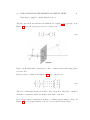
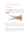
An overview first. Each camera image plane has its own bi-dimensional coordinate
system. Thanks to the calibration of the cameras and the depth maps it is possible to
transform the coordinate points from that bi-dimensional space to the three-dimensional
coordinate system common to all the cameras. This is why the transformation between
a 2D point to a 3D one was studied in the chapter Background Information.
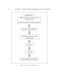
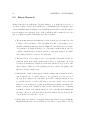
To perform the projection, the following steps should be followed:
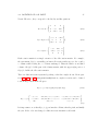
1. De-normalize the depth map. The goal is to determine the z-coordinate on the
reference coordinate system for each pixel on the reference image plane.
2. Carry out an inverse projection from the reference image plane to the 3D space.
3. Define the new camera parameters and project the available 3D points in order
to determine its position in the new camera’s image plane.
Depth-map normalization
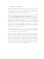
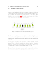
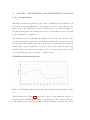
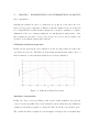
Zpoint =
1
d
255
∗
1
( Zmin
−
1
Zmax )
+
1
Zmax
(3.1)
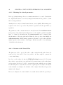
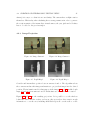
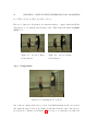
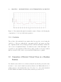
The depth values are in the corresponding depth map, a gray-scale image with range
between 0 to 255. The scenario is situated between a minimum and a maximum distance
(Zmin and Zmax respectively), so Zpoint is the Z coordinate on the common camera’s
coordinate system, corresponding to a given pixel with depth value d.
For each set of images the Zmin and Zmax values have to be known in order to obtain
the correct z-coordinate on the projection algorithm.
Inverse Projection: 2D to 3D
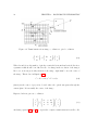
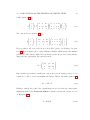
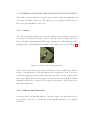
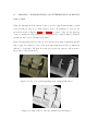
Now the goal is to know the X and Y coordinates in the 3D scenario of a certain point
in the image. The procedure is based on the perspective projection from Euclidean 3space, seen in Equation 3.2. The nature of P, the Projection Matrix, has been explained