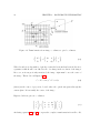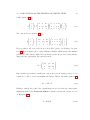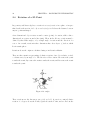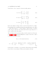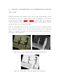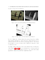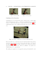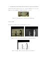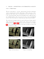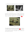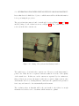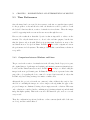
1
3D Visualization using virtual view generation for stereoscopic hardware Jordi de la Torre Lara Directors: Javier Ruiz Hidalgo, Ramon Morros Rubio February 2010 2 Contents 1 Introduction 7 1.1 3D Virtual Views . . . . . . . . . . . . . . . . . . . . . . . . . . . . . . . 7 1.2 Objectives . . . . . . . . . . . . . . . . . . . . . . . . . . . . . . . . . . . 8 1.3 Overview of the Project . . . . . . . . . . . . . . . . . . . . . . . . . . . 10 2 Background Information 13 2.1 Stereoscopic Vision . . . . . . . . . . . . . . . . . . . . . . . . . . . . . . 13 2.2 Accelerometer. A theoretical aproach . . . . . . . . . . . . . . . . . . . . 15 2.2.1 Usage . . . . . . . . . . . . . . . . . . . . . . . . . . . . . . . . . 17 Basic Notions on the Creation of Virtual Views . . . . . . . . . . . . . . 17 2.3.1 Camera Model and its Parameters . . . . . . . . . . . . . . . . . 19 Rotation of a 3D Point . . . . . . . . . . . . . . . . . . . . . . . . . . . . 24 2.3 2.4 3 State of the Art 3.1 Virtual View Generation Methods . . . . . . . . . . . . . . . . . . . . . 27 3.1.1 Model-based rendering . . . . . . . . . . . . . . . . . . . . . . . . 28 3.1.1.1 Active methods . . . . . . . . . . . . . . . . . . . . . . 28 3.1.1.2 Passive methods . . . . . . . . . . . . . . . . . . . . . . 29 Image-based rendering . . . . . . . . . . . . . . . . . . . . . . . . 30 3.1.2.1 Seitz-Dyer . . . . . . . . . . . . . . . . . . . . . . . . . 30 3.1.2.2 Brief Explanation of the 3D Reconstruction used in this 3.1.2 3.2 27 Project . . . . . . . . . . . . . . . . . . . . . . . . . . . 31 Different 3D Devices . . . . . . . . . . . . . . . . . . . . . . . . . . . . . 33 3.2.1 34 eDimensional Wireless 3D Glasses . . . . . . . . . . . . . . . . . 3 4 CONTENTS 3.2.2 Vuzix iWear VR920 . . . . . . . . . . . . . . . . . . . . . . . . . 35 3.2.2.1 Calibration . . . . . . . . . . . . . . . . . . . . . . . . . 36 3.2.2.2 Errors in the Accelerometer of the VR920 . . . . . . . . 37 3.2.2.3 Linux incompatibility . . . . . . . . . . . . . . . . . . . 38 4 Virtual Views Generator Tool. Algorithm 4.1 4.2 Reproducing Sequences in the VR920 . . . . . . . . . . . . . . . . . . . 39 4.1.1 Direct3D Textures and Devices . . . . . . . . . . . . . . . . . . . 40 Creation of Stereoscopic Virtual Views . . . . . . . . . . . . . . . . . . . 41 4.2.1 Automatic Camera Selection . . . . . . . . . . . . . . . . . . . . 43 4.2.2 Obtaining the virtual parameters . . . . . . . . . . . . . . . . . . 44 4.2.2.1 Rotation of the Virtual View . . . . . . . . . . . . . . . 44 4.2.3 Image Projection . . . . . . . . . . . . . . . . . . . . . . . . . . . 45 4.2.4 Composition . . . . . . . . . . . . . . . . . . . . . . . . . . . . . 46 4.2.5 Gaps and Occlusions . . . . . . . . . . . . . . . . . . . . . . . . . 47 5 Implementation and interpretation of results 5.1 50 5.1.1 Yaw Error . . . . . . . . . . . . . . . . . . . . . . . . . . . . . . . 50 5.1.1.1 Compensation . . . . . . . . . . . . . . . . . . . . . . . 54 Conclusion . . . . . . . . . . . . . . . . . . . . . . . . . . . . . . 58 Generation of Rotated Virtual Views in a Random Position . . . . . . . 58 5.2.1 Corners . . . . . . . . . . . . . . . . . . . . . . . . . . . . . . . . 59 5.2.2 Different Basic Rotations . . . . . . . . . . . . . . . . . . . . . . 59 5.2.2.1 Roll . . . . . . . . . . . . . . . . . . . . . . . . . . . . . 60 5.2.2.2 Pitch . . . . . . . . . . . . . . . . . . . . . . . . . . . . 63 5.2.2.3 Yaw . . . . . . . . . . . . . . . . . . . . . . . . . . . . . 65 How to deal with gaps, occlusions and other issues . . . . . . . . 67 5.2.3.1 Interpolation . . . . . . . . . . . . . . . . . . . . . . . . 68 5.2.3.2 A Third Camera . . . . . . . . . . . . . . . . . . . . . . 72 5.2.3.3 Two Separated Cameras . . . . . . . . . . . . . . . . . 74 Time Performance . . . . . . . . . . . . . . . . . . . . . . . . . . . . . . 76 5.3.1 76 5.2.3 5.3 49 Accelerometer in the iWear VR920 . . . . . . . . . . . . . . . . . . . . . 5.1.2 5.2 39 Comparison between Windows and Linux . . . . . . . . . . . . . CONTENTS 5 6 Conclusions 6.1 6.2 79 Conclusions and Contributions . . . . . . . . . . . . . . . . . . . . . . . 79 6.1.1 An applicaction . . . . . . . . . . . . . . . . . . . . . . . . . . . . 80 Future Research . . . . . . . . . . . . . . . . . . . . . . . . . . . . . . . 82 7 Bibliography 85 8 Annex 89 8.1 Direct3D . . . . . . . . . . . . . . . . . . . . . . . . . . . . . . . . . . . . 89 8.1.1 Textures . . . . . . . . . . . . . . . . . . . . . . . . . . . . . . . . 90 8.1.2 Devices . . . . . . . . . . . . . . . . . . . . . . . . . . . . . . . . 91 Rotated Virtual Views . . . . . . . . . . . . . . . . . . . . . . . . . . . . 92 8.2.1 Combinated Rotations . . . . . . . . . . . . . . . . . . . . . . . . 92 8.2.1.1 Pitch and Yaw . . . . . . . . . . . . . . . . . . . . . . . 93 8.2.1.2 Pitch, Yaw and Roll . . . . . . . . . . . . . . . . . . . . 94 8.2 6 CONTENTS Chapter 1 Introduction 1.1 3D Virtual Views In these early years of the new millenium, the rising possibilities of 3D technology have led to an important and unfinished effort in order to turn several fields into amazing immersing experiences, being the most important entertainment. Its applications in videogames go beyond the wildest dreams of our predecessors, and the possibility of actually living a movie as one of the characters is no longer a chimera, and is regarded as a way to take people back to the cinemas and thus fight piracy. Figure 1.1: VirtualView In order to introduce the viewer into a certain scene, giving them the feeling of being inside a 3D environment, plenty of information about it is necessary. It must be previously recorded by different cameras from several points of views, so that they all 7 8 CHAPTER 1. INTRODUCTION together cover every angle. The previous situation leads to Multiview video (MVV) applications. If the goal is to have a full 3D representation of the scene, so that the viewer can move freely around it and have a view of every spot, an excessive number of cameras should be used, and consequently, two much memory and CPU would be required. Hence, the creation of virtual views stands as a major challenge, as a way of reducing the number of cameras by reconstructing a specific point of view from the information of two nearby cameras. A clear example would be the scene in Figure 1.1. If the purpose is to move around the kitchen with total freedom, it is necessary to have the information from different cameras covering the area. For instance, the current view makes it impossible to see whether there is something behind the table or not, while a camera placed one meter on the right might provide more information. Then, if both informations were combined, every spot could be reconstructed by one or the other image. 1.2 Objectives Sometimes, the available cameras cannot provide images of a certain position in a concrete scene, and then, instead of using more cameras, which may not be possible in some cases, image processing techniques reconstruct the desired view, taking into account the position and the rotation desired, and using images from the nearest cameras, as long as other information. The idea, always, is to recreate the maximum space with a reduced number of cameras, which would be the first goal of the project: the creation of virtual views. Another example of this can be seen in Figure 1.2, where there is a circular room surrounded by eight cameras. Each of them is placed in a different spot so they all together cover a major part of the scene. Therefore, using the information of two of them, considering the redundancy in their images, it is possible to create a virtual camera in any position between the original ones. 1.2. OBJECTIVES 9 Figure 1.2: FreeViewpoint However, sometimes two cameras are unable to provide enough information about a certain position, and then it is necessary to interpolate the missing pixels with the ones around them, or even, if the unknown regions are wide enough, use a third camera. Unfortunately, due to the involved computational complexity, it is difficult to perform this process in real-time. At this point, a virtual view can be recreated in a certain position, the viewpoint freely chosen by the user, with information from some cameras distributed on the area. But the second goal is to have 3D views. It is now time to introduce the stereoscopic effect. It consists on two slightly different images sent to each eye so that the brain mix them creating a 3D image. In order to do so, the information must be send to a device, a pair of glasses that the user must wear. As they move around a scene (which is not actually the one he is seeing), or rotates his head, the new views must be generated and shown to them. 10 CHAPTER 1. INTRODUCTION The device used for that purpose is the Vuzix iWear VR920 [3], the so-called first video eyewear to let you step inside virtual worlds, MMOs (massively multiplayer online game) and 3D games. It provides information about the relative movement, and therefore angles of rotation, using the acceleremoters, devices that will be explained in the next chapter. To summarize, the final purpose is to create a compact tool that generates virtual stereo views at a desired position, being able to move and rotate it, from the information of several cameras spread in the area. These views will allow to visualize the scene in 3D, using a device that reproduces the stereoscopic effect, from the current point of view. 1.3 Overview of the Project The document is divided into five main sections, from Chapter 2 to Chapter 6. Each of them is a step towards the final goal: the creation of virtual 3D Views in a Free Viewpoint environment using a specific device (the Vuzix iWear VR920). In Chapter 2, some basic information will be provided regarding the theoretical concepts on which the whole project will be constructed. There will be a brief explanation about stereoscopic vision and how it is used in order to have a 3D Virtual View. Moreover, the concept of accelerometer, which was mentioned when introducing the glasses, and its usage, will also be clarified. Once those concepts have been studied, there will be a brief explanation in Chapter 3, State of the Art, of the different devices available to show the virtual views in 3D, and among them, the so-called iWear VR920 , which will be the one used in the project. Finally, the process of creating 3D virtual views, will also be dealt with here. Those views must be at any point in a scene, and rotated in any direction the user wants. The next two chapters might be considered the core of the project. In the fourth, Virtual Views Generator Tool: Algorithm, the developed program will be studied. 1.3. OVERVIEW OF THE PROJECT 11 There are two differenciated parts in the project: the interaction with the device and the generation of the virtual views. The second part has already been studied in other projects, and in this one, several functions already created by other students of the department are used, others being modified and some created. After the fourth chapter, where the necessary background for the project is concluded, in the fifth, Implementation and Interpretation of Results, the behaviour of the accelerometer in the VR920 and the virtual views obtained will be tested. Different rotations, and the problems that may appear during the process of constructing them, with possible solutions, will be the main part of the section. Moreover, computational performance will also be tackled here, comparing the results of the different alternatives. In the last section, Chapter 6, Conclusions, a comparison will be done between the initial goals of the project and the final results achieved, as long as a brief explanation of the possible lines of future research in the area. In the end, the different parts of the project become a single unity, as a powerful tool able to work with the device in the creation of virtual views and showing 3D sequences of a certain scene with a reduced number of information. Finally, it is necessary to say that this project is actually, in some way, the culmination of many others developed in the last years in the Image Processing Group in UPC. Creation of virtual views is a subject which has been studied by some colleagues for their own projects. However, in order to make a strong tool, some aspects have been improved, as long as developing some new software as far as rotation is concerned. Also, one of the biggest challenges was to join all the previous work and use it in a physical device, the VR920. The final result is a promising experience, putting into practice with in a real case all the software developed during the last years. 12 CHAPTER 1. INTRODUCTION Chapter 2 Background Information 2.1 Stereoscopic Vision In order to understand how a certain scene will be constructed from different 2D images into a 3D Virtual View, the first step is to clarify the concept of steoscopic vision (also known as stereographic vision). What it is, and how it is used, will provide a tool to convert single 2D views into complete inmersing scenes. Most of the animals (including humans) have steoscopic vision. Objects are seen with two eyes simultaneously, both set in the same plane. Of course, there are exceptions, for instance fishes, with their eyes located on opposite sides of the head. They generate and independent image in each eye, while in humans, the image in each retina is only slightly different, as we can see in Figure 2.1. The two images will be far more different for an object which is near the viewer than in the case that the object is far away. This effect is imperceptible for distant objects such as mountains. Afterwards, the perceptions of the eyes are combined in the brain, and interpreted in terms of depth and distances to the objects seen. The final picture that is created in the human brain is a 3D stereo image. 13 14 CHAPTER 2. BACKGROUND INFORMATION Figure 2.1: Stereoscopic Vision The main feature of stereo vision is the ability to see objects as solid in three spatial dimensions–width, height and depth (x, y and z), being the added perception of the depth dimension the most important, thanks to which it is possible to locate objects in relation to a specific point. It is so important that stands as the major reason why some species are hunters while others are hunted. Stereoscopic vision allows the hunters to know how far away their food is. Most predators (humans, lions, wolves, tigers...) have it. Hunted animals, however, need to see danger coming from all directions, not just in front of them. This is why they have eyes on the sides or on top of their heads (deers, squirrels, most birds...). Figure 2.2: Stereoscopic Vision in Humans Human eyes have an overlapping field of view of about 120◦ . It is only in this field that they have stereoscopic vision. Beyond this 3-D area out to 160-180◦ , objects are seen 2.2. ACCELEROMETER. A THEORETICAL APROACH 15 only in two dimensions, without depth. People looking at a stereoscopic picture may find the third dimension develops slowly. The longer they look, the more computation the brain gets through and the 3D impression gets better. Therefore, stereoscopic vision is partly a learned response. One of the goals of this project is to reproduce the process using a certain device. Two 2D images will be necessary to create a 3D one, each of which must show the same scene from slightly different positions. The separation between them will be 6cm aproximately, the standarized eye separation. The process followed to obtain a 3D image is a projection of the one taking place in the brain. The device used to do that is called iWear VR920, and it will be extensively studied in further chapters. It must be pointed out that this process is already used in several applications nowadays. In most cases, the same scene is recorded twice using different cameras. Using image processing techniques , it is possible to achieve the same results with a reduced number of cameras, generating the missing views from the ones available. Needless to say, it has many benefits, from economical to computational. 2.2 Accelerometer. A theoretical aproach An accelerometer is an electromechanical device that measures acceleration forces. These forces may be static, like gravity, or they could be dynamic - caused by moving or vibrating the accelerometer. They are always measured in relation to freefall. The accelerometer can be divided into two parts: the first, a single-degree-of-freedom vibrating mass, which converts the acceleration into a movement; the second, a transducer converting the displacement of the mass into an electric signal. They both can have different natures. The first one has two possibilities: • Spring-Retained Seismic Mass. In most accelerometers, acceleration forces a seismic mass, that is damped, and restrained by a spring, so that it moves relative 16 CHAPTER 2. BACKGROUND INFORMATION to the casing along a single axis. The displacement of the mass and the extension of the spring are proportional to the acceleration only when the oscillation is below the natural frequency. • Double-Cantilever Beam. Few accelerometers use it. The dual-cantilever beam can be modeled as a spring-mass-dashpot. Accelerometers have developed from a simple water tube with an air bubble that showed the direction of the acceleration to an integrated circuit that can be placed on a circuit board. They are currently small micro electro-mechanical systems (MEMS), consisting of little more than a cantilever beam with a proof mass. Future advancements will use nanotechnology, dramatically reshaping this area. There are several types of accelerometers, depending on how they measure the acceleration, or in other words, depending on the nature of the second transducer (how they produce the electric signal). Some of the most important are shown on Table 2.1: Type of Accelerometer Capacitive Features The accelerometer senses the capacitance change between a static condition and the dynamic state Piezoelectric Use materials such as crystals, which generate electric potential from an applied stress (piezoelectric effect) Magnetoresistive Measures changes in resistance due to a magnetic field. Hall Effect measure voltage variations stemming from a change in the magnetic field around the accelerometer Heat transfer A single heat source is centered in a substrate and suspended across a cavity. Thermoresistors are spaced on all four sides of it. Under zero acceleration the heat gradient is symmetrical, and it becomes asymmetrical under any acceleration Table 2.1: Different Types of Accelerometers Currently, they can measure: vibrations (to isolate the vibration of mechanical systems from outside forces), shocks, impacts (determine the severity of it), tilt and motion of 2.3. BASIC NOTIONS ON THE CREATION OF VIRTUAL VIEWS 17 an object. The last feature is extremely helpfull if the purpose is to walk around an area and have information of the position constantly, or at least, of the rotation of the device in order to generate the proper virtual view. That is the reason for using a device as the one chosen, the iWear VR920. Not only it allows to show two images (one for each eye) and therefore enables stereoscopic effect, but is has three accelerometers inside, with the consequent motion information. 2.2.1 Usage Accelerometers have many applications. These range from triggering airbag deployments to the monitoring of nuclear reactors. Cell phones (being the iPhone a good example), computers and washing machines nowadays contain then. They can be used to measure the performance of an automobile, the vibration of a machine or the motions of a bridge. They are useful in computer peripherals, and essencial in head mounted displays (being the iWear VR920, the center of this project, one of the latest models). They also have medical applications, such as patient monitoring (emergency call), hospital bed control and physical therapy. As an example of its popularity, IBM and Apple have recently started using accelerometers in their laptops to protect hard drives from damage. In case the laptop is accidentally dropped, the accelerometer detects the sudden freefall, and switches the hard drive off so the heads don’t crash on the platters. In a similar fashion, they are the industry standard way of detecting car crashes and deploying airbags at just the right time. 2.3 Basic Notions on the Creation of Virtual Views Although in the next chapter, State of the Art, the used method to create the virtual views will be studied, it is necessary to have some knownledge of certain concepts before. 18 CHAPTER 2. BACKGROUND INFORMATION The scene has several cameras on it, and the virtual views are created in intermediate positions between them. Therefore, each of the cameras has to be completely characterized. Three items are required for that purpose: • The image that each of the cameras provide. In Figures 2.3 and 2.4 there are the views from camera 1 and 2. They are very similar, as the cameras are separated few centimeters, a feature that will make it possible to reconstruct intermediate views from their redundancy. Figure 2.3: Camera 1 Figure 2.4: Camera 2 • The depth map: a two-dimensional array where the x and y corresponds to the rows and columns of pixels of an ordinary image, and depth readings (z values) are stored in the element, scaled and represented with values between 0 (the furthest) 255 (the nearest). Depth map is like a grey scale image except the z information replaces the intensity information. Figure 2.5: Depth Map Camera 1 2.3. BASIC NOTIONS ON THE CREATION OF VIRTUAL VIEWS 19 • The camera parameters. They are divided into intrinsic and extrinsic. The intrinsic include the most relevant internal parameters of the camera and the parameters of the sensor, while the extrinsic ones determine the position and the rotation of the camera. But before getting into details with them, it is important to understand the camera model that is used, as the parameters strongly depend on it. 2.3.1 Camera Model and its Parameters The model used is called the Pinhole Camera Model [1]. The principle of a pinhole camera is simple. In it, light rays from an object, in the case of Figure 2.6 a tree, pass through a small hole to form an image (an inverted one) in a plane (one side of the box). The pinhole camera can be described, therefore, as a light-proof box with a hole in one side. The model states that the camera is fully caracterized with the hole, which is called aperture, and the plane where the image is projected. The reason for using this model is that is assumes perfect pinhole cameras, hence measuring with infinite accuracy the image in <2 . Also, the principal point is in the center of the image. On the other hand, physical camera lenses provide distorted imaging projections, finite resolutions defined by the sensing devices in digital cameras, and offset between image center and optical center. Considering a certain point p = [X, Y, Z]T ∈ <3 and its image x = [x, y]T ∈ <2 , as in Figure 2.7 where x : X = y : Y = -f : Z being f the perpendicular distance between the aperture and the image plane. Then x = −f X/Z and y = −f Y /Z 20 CHAPTER 2. BACKGROUND INFORMATION Figure 2.6: Pinhole camera. An example of a projection Figure 2.7: Pinhole camera model. The image is inverted In Figure 2.6, as long as in the last equation, it is noted that the mapping from 3D to 2D coordinates is not only a perspective projection, but also a 180o rotation of the image. In order to produce an unrotated image, which is what is expected from a camera, there are two possibilities: • Rotate the coordinate system in the image plane 180o (in either direction). • Place the image plane so that it intersects the X axis at f instead of at -f and rework the previous calculations. This would generate a virtual (or front) image plane which cannot be implemented in practice, but provides a theoretical camera 2.3. BASIC NOTIONS ON THE CREATION OF VIRTUAL VIEWS 21 which may be simpler to analyse than the real one. The first option is chosen, and then, the initial model of Figure 2.7 becomes the one in Figure 2.8, where the point (x,y) can now be expressed as: x ! X = f /Z y ! (2.1) Y Figure 2.8: Frontal Pinhole camera model. The coordinate system in the image plane is rotated 180o In homogenous coordinates, the Equation 2.1 can be expressed as: x f Z y = 0 1 0 0 f 0 0 0 X Y 0 0 Z 1 0 1 (2.2) The need for this transformation from 2D to 3D (or from 3D to 2D) will be explained when the reconstruction method is analised in the State of the Art. Now, it is necessary to transform from image coordinates (meter units) to pixels. In Figure 2.9 there is a representation of the process. It is divided in two stages. 22 CHAPTER 2. BACKGROUND INFORMATION Figure 2.9: Transformation from image coordinates to pixel coordinates Xs Ys ! = Sx 0 0 Sy ! x ! (2.3) y Where Sx and Sy are the number of pixels per cm in the horizontal and vertical direction, a parameter that should be modified in case of a change in the resolution of the images. Moreover, as it was previously mentioned, the image origin must be now the center of the image. This is done in Equation 2.4 x0 = Xs + Ox; y 0 = Y s + Oy. (2.4) (Ox,Oy) is the center of projection, located where the optical axis passes through the camera plane. It is normally the center of the image. Expressed in homogeneous coordinates: x0 Sx y0 = 0 1 0 0 Sy 0 Ox x Oy y 1 1 (2.5) And using equation 2.2 and 2.5 to express the complete transformation from 3D to 2D, 2.3. BASIC NOTIONS ON THE CREATION OF VIRTUAL VIEWS 23 results equation 2.6 x0 Sx 0 Z y = 0 0 1 0 Sy 0 f 0 0 Oy 0 0 1 f 0 Ox 0 x 0 y 1 1 0 0 (2.6) Also expressed as in equation 2.7 x0 0 Z y = 1 f Sx 0 0 f Sy 0 0 x 1 0 0 0 Oy 0 0 1 1 0 0 1 0 y 1 0 Ox (2.7) However, this is only a projection from a 3D world to pixels of a 2D image. In equation 2.7, there is include the so-called Calibration Matrix, which includes the intrinsic parameters of the camera. Named K, it is included in the file provided along with the images and the depth maps. Its generical form is: K= f Sx 0 0 f sθ Ox f Sy Oy 0 1 (2.8) But sometimes (most times actually), the camera is not in the (0,0,0) position, so it is required to be able to rotate and translate the images. This is done using equation 2.9. Xw = RX + T (2.9) Finally, to sum up, the points of the original images are projected into the camera plane multiplying them by the Projection Matrix, being the general form of it the one seen on Equation 2.10. P = K[R|T ] (2.10) 24 2.4 CHAPTER 2. BACKGROUND INFORMATION Rotation of a 3D Point In geometry and linear algebra, a rotation is a transformation in a plane or in space that describes the motion of a body around a fixed point. It leaves the distance between any two points unchanged. A two-dimensional object rotates around a center (point) of rotation, while a threedimensional one rotates around a line (axis). Then, in the 3D case, rotation must be defined by three Euler angles, or by a single angle of rotation and the direction of a vector. As a result, rotation in three dimensions have three degree of freedom, which lies in a unit sphere. Rotations about the origin are calculated using a 3x3 Rotation Matrix. There are three matrices representing clockwise rotations of an object relative to fixed coordinate axes, by an angle of α. The direction of the rotation: Rx rotates the y-axis towards the z-axis, Ry rotates the z-axis towards the x-axis, and Rz rotates the x-axis towards the y-axis. Figure 2.10: angles These rotations are also known as yaw, pitch and roll. A yaw is a counterclockwise rotation of α degrees about the Z axis, a pitch about the Y axis, and a roll about the 2.4. ROTATION OF A 3D POINT 25 X axis. Therefore, they correspond to the Rx, Ry and Rz equations. 1 Rx = Rroll = 0 0 Ry = Rpitch = 0 0 sin α cos α cos α − sin α cos α 0 − sin α 0 1 0 sin α 0 cos α cos α Rz = Ryaw = − sin α 0 (2.12) sin α 0 cos α 0 1 0 (2.11) (2.13) Each rotation matrix is a simple extension of the 2D rotation matrix. For example, the yaw matrix, Rz (α) , essentially performs a 2D rotation with respect to the x and y coordinates while leaving the z coordinate unchanged. Thus, the third row and third column of Rz (α) look like part of the identity matrix, while the upper right portion of Rz (α) looks like the 2D rotation matrix. There are different rotation systems depending on the three angles chosen. From equations 2.11, 2.12 and 2.13, using matrix multiplication, complete rotation can be obtained towards any position in the 3D space. R(α, β, γ) = Ryaw(α)Rpitch(β)Rroll(γ) cos β cos α R(α, β, γ) = − cos β sin α sin β (2.14) − sin γ sin β cos α + cos γ sin α − cos γ sin β cos α + sin γ sin α − sin γ sin β sin α + cos γ cos α cos γ sin β sin α + sin γ sin α − sin γ cos β cos γ cos β (2.15) It is important to note that R(α, β, γ) performs the roll first, then the pitch, and finally the yaw. If the order was changed, a different rotation matrix would result. 26 CHAPTER 2. BACKGROUND INFORMATION Chapter 3 State of the Art Generation of Virtual Views and its usage in videogames, movies and even military purposes, is an area of current study, where advances are made every day. In the UPC Image Processing Department, several functions are being developed in order to achieve the reconstruction of those views as perfect as possible. In this project, as it was said previously, the main purpose is to use this software in a real case, using a helmet that shows the views in 3D. From the information of different cameras in a remote scene, a person wearing it might walk through an empty room and see himself immersed in that virtual world. 3.1 Virtual View Generation Methods In order to generate images from any virtual view point between two selected real views (from the two nearest cameras), there are two different rendering approaches. The first one is using a 3D model (shape reconstruction), a technique called model-based rendering. The other is image-based rendering (IBR), where the shape of the objects in the scene is not taken into account. After an explanation of the main characteristics of each, some examples will be presented. 27 28 3.1.1 CHAPTER 3. STATE OF THE ART Model-based rendering In this model, the geometry of the real scene is recovered and then rendered from desired virtual view points. In this context the research is focused on improving model fidelity by using image-based modeling. In particular: geometric model extraction and representations for rendering purposes, object-texture extraction and mapping to geometric models, illumination effects recovery and rendering. At a high level a model-based rendering approach involves three processes. First, an event or a scene must be recorded, then, a 3D model of the environment has to be extracted using computer vision techniques, and finally, the obtained 3D model is rendered from the view of a virtual camera. Methods for the automatic construction of 3D models have found applications in many fields, including Mobile Robotics, Virtual Reality and Entertainment. They fall into two categories: active and passive methods. 3.1.1.1 Active methods They often require laser technology and structured lights or video, which might result in very expensive equipments. However, new technologies have extended the range of possible applications, (Levoy et al. [11]), and new algorithms have solved many problems inherent to laser scanning, (Castellani and Livatino [13]). An example of this is the Digital Michelangelo Project. The target of this project [11] was to be able to store the information of a piece of art, and thus, Professor Marc Levoy has been investigating methods for digitizing the shape of three-dimensional objects using laser scanners. Before him, nobody had digitized a large statue with enough precision to serve as a primary resource for scientific work. 3.1. VIRTUAL VIEW GENERATION METHODS 29 Figure 3.1: David 3D Reconstruction 3.1.1.2 Passive methods They involve generating a 3D model given multiple 2D photographs of a scene. There are different ways of doing it, from simple 3D silhouette models dynamically cut-out and texture-mapped from video-sequences, (Livatino and Hogg, [14]), to polyhedral visual hulls generated by multiple-view silhouettes 2and estimated stereo disparities, (Li, Schirmacher and Seidel, [15]). In general they do not require a very expensive equipment, but a specialized set-up, (Fuch [12]). For example, Fuch’s paper [12] proposes the use of image data acquired by many stationary cameras installed around a small environment such as a conference room and the use of stereo methods to compute time-varying 2.5-D depth maps representing the scene geometry. The depth maps are updated, maintained, and then combined to create a virtual scene from viewer current position and orientation. The data can be acquired in a remote site while the viewer position and orientation is local. A depth image of a human subject is calculated from 11 closely spaced video camera positions. The user is wearing a head-mounted display and walks around the 3D data that has been inserted into a 3D model of a simple room. The system is suitable for teleconferencing applications, provide 3D structure of events for virtual reality applications, safe training, user guided visualization of events. However, only play-back is allowed, because the speed of the algorithm is limited by the 30 CHAPTER 3. STATE OF THE ART poor machine performance. 3.1.2 Image-based rendering This approach relies on real images taken as reference in place of a geometric 3D model. However, input reference images sometimes are not enough for the purpose of rendering novel views, so that many of the proposed systems require additional knowledge, such as image-correspondences, depth information, epipolar relations, etc. This will be the used method in this project. The advantage avoiding model reconstruction is no software rendering and no exploitation of graphic hardware. Image-based rendering methods were developed in the half of the nineties (some of them are Chen [16] and Seitz and Dyer [17] [18]). Research is still very active in the field and new techniques have also been proposed for investigation. For example, the new projection model based on the two-slit camera (Granum [19]). 3.1.2.1 Seitz-Dyer S.M. Seitz and C.R. Dyer propose View Morphing [17] [18], a way to generate new views of a scene from two basis views. This can be applied to both calibrated and uncalibrated images. At minimum, two basis views and their fundamental matrix are needed. The proposed technique uses basic principles of projective geometry, and introduces an extension to image morphing that correctly handles 3D projective camera and scene transformations. The authors propose to exploit monotonicity along epipolar lines to compose physically valid intermediate views without the need for full correspondence information. Under the assumption of monotonicity, it is shown that the problem is theoretically well-posed. 3.1. VIRTUAL VIEW GENERATION METHODS 31 This result is significant in light of the fact that is not possible to fully recover the structure of the scene due to the aperture problem 1 . Moreover, they demonstrate that for a particular range of views, the problem of view synthesis is in fact well-posed and does not require a full correspondence, that is, images interpolation is a physically valid mechanism for view interpolation. Views can consequently be generated by linear interpolation of the basis images. Among the advantages: the method represents a practical and simple way of generating new views of a scene (under monotonicity assumptions), view synthesis does not suffer from the aperture problem, the technique may be applied to photographs as well as rendered scene, ability to synthesize changes both in viewpoint and image structure, interesting 3D effects via simple image transitions, applicable to both calibrated and uncalibrated images, suitable for application in entertainment industry and for limited bandwidth teleconferencing. Among the disadvantages: the method requires multiple image re-sampling (loss of quality), local blurring when monotonicity assumption is violated, artifacts arising from errors in correspondence, it is only suitable for static scenes, the method needs four user provided feature correspondences, visualized regions need to be free of occluders. There are different approaches to this method: implicit-geometry rendering [20], volumetric reconstruction [21], geometric-valid pixel reprojection [22]. 3.1.2.2 Brief Explanation of the 3D Reconstruction used in this Project For the reconstruction of the scenes, an Image-based rendering method has been used, very similar to the one used by Seitz-Dyer [17][18]. It is based on a projection algorithm, used by Carolina Martinez in his PFC [7]. The idea is to find the position of each of the pixels of the image of the reference camera into the virtual camera’s image plane. 1 ”The Aperture problem arises due to uniformly colored surfaces in the scene. In the absence of strong lighting effects, a uniform surface in the scene appears nearly uniform in projection. It is then impossible to determine correspondences within these regions” 32 CHAPTER 3. STATE OF THE ART An overview first. Each camera image plane has its own bi-dimensional coordinate system. Thanks to the calibration of the cameras and the depth maps it is possible to transform the coordinate points from that bi-dimensional space to the three-dimensional coordinate system common to all the cameras. This is why the transformation between a 2D point to a 3D one was studied in the chapter Background Information. To perform the projection, the following steps should be followed: 1. De-normalize the depth map. The goal is to determine the z-coordinate on the reference coordinate system for each pixel on the reference image plane. 2. Carry out an inverse projection from the reference image plane to the 3D space. 3. Define the new camera parameters and project the available 3D points in order to determine its position in the new camera’s image plane. Depth-map normalization Zpoint = 1 d 255 ∗ 1 ( Zmin − 1 Zmax ) + 1 Zmax (3.1) The depth values are in the corresponding depth map, a gray-scale image with range between 0 to 255. The scenario is situated between a minimum and a maximum distance (Zmin and Zmax respectively), so Zpoint is the Z coordinate on the common camera’s coordinate system, corresponding to a given pixel with depth value d. For each set of images the Zmin and Zmax values have to be known in order to obtain the correct z-coordinate on the projection algorithm. Inverse Projection: 2D to 3D Now the goal is to know the X and Y coordinates in the 3D scenario of a certain point in the image. The procedure is based on the perspective projection from Euclidean 3space, seen in Equation 3.2. The nature of P, the Projection Matrix, has been explained 3.2. DIFFERENT 3D DEVICES 33 in the Background Information Chapter, its final expression in 2.10. X and Y should be isolated in the equation, where the known variables are x, y and Z (previously calculated). x y =P 1 X X Y · Z 1 (3.2) x Y = P −1 · y Z 1 1 (3.3) Recapturing the Image: 3D to 2D Once the reference camera image points have been projected onto the 3D scene, the projection algorithm is done to recapture the image in the virtual camera’s image plane. Now equation 3.2 can be used straight. Then, with the new coordinates for each point, the pixel values from the original image can be copied into the virtual camera’s image plane. The virtual view can therefore be created. 3.2 Different 3D Devices First of all, a complete 3D experience is not possible without a special Stereo-3D software and hardware. There are two basic types; still, the goal is the same for both: guarantee that the eyes get the images from the projector, differently for each one, and combine them creating the stereoscopic effect: 34 CHAPTER 3. STATE OF THE ART Figure 3.2: Glasses Figure 3.3: Helmets • Glasses which just influence the way the image is seen on a standard monitor: Liquid Crystal-Shutterglasses, Polarization Glasses. This last type includes two polarizing lenses which have their polarization directions adjusted to be 90 degrees different. This makes is possible that one eye sees the picture but for the other it seems black. They are used in conjunction with a cathode-ray-tube-monitor or projector. This is the type used in cinemas. • Devices which actually produce an image: VR-Helmets, Head Mounted Devices... In a virtual reality (VR) helmet each eye is given a small monitor (LCD or CRT screen) to watch and the computer creates the proper left or right images for each. Since the computer can monitor the position of the helmet it can continuously change the images seen by the viewer to match his movements. This can give the viewer the sensation he is moving in a computer generated world. 3.2.1 eDimensional Wireless 3D Glasses Figure 3.4: Wireless 3D Glasses Its main advantage is that no USB or serial ports are required for the installation. After installing the software once, using an infrared transmitter for wire-free operation of the glasses, this system gives a wide viewing angle and range available and is used to beam a signal to perfectly synchronize the refresh rate of the monitor with the glasses. 3.2. DIFFERENT 3D DEVICES 35 Additional users need only an additional set of eyewear to simultaneously view 3D. It uses the so-called TrackIR2, an infra-red sytem to track your head movements, using technology created for military targeting systems. As the head is moving, the TrackIR2 sends a real-time stream of instructions to the computer via USB to move the mouse pointer or pan the view in game play. The depth-of-field is simulated using shutter-glasses with lenses that can alternate between clean and opaque (blocks light). A left eye image is first displayed on a computer monitor, and the shutter-glasses left lens is clear, while the right lens is dark. The image on the monitor is then switched to the right-eye view, and the lens of the shutterglasses is reversed. This switching occurs many times per second, and the brain fuses the images creating the 3D effect. Unfortunately, its most remarkable drawback is the fact that it is not possible to communicate with the glasses through software, and two separate images cannot be sent to each of the screens, which is the intention of this project. The device follows the process explained previously, using the same image for both eyes. 3.2.2 Vuzix iWear VR920 The device chosen fits perfectly the initial requirements. It can be used to test the stereoscopic effect, as it has two screens, one for each eye, and allows to develop a program that creates the two virtual views and sends each one to a specific screen. The refresh rate of the device is 60Hz, and different views have to be generated in real time and be sent as it moves though the scene, in order to give the sensation of actually being there. The purpose is to introduce the user in a virtual reality of a distant location. However, working in real time is not easy, as it will be seen in further chapters. The VR920 is able support resolutions of 1024x768, 800x600 and 640x480 pixels, a very important feature as it would be disappointing to inmerse yourself in a virtual world where the quality of the images is poor. The device also includes a microphone and earphones so the experience is fullfilling. However, the main problem is that it must be 36 CHAPTER 3. STATE OF THE ART Figure 3.5: Vuzix iWear VR920 connected to the computer throught a USB and a VGA connector. Therefore, it results in a lack of mobility. The eyewear has a cable that splits into two with a USB connector on one (for the data transmision) and a VGA connector on the other. There are two possible configurations, depending on whether the computer has two graphic ports or only one. It must be pointed out that the device can also be connected to a single VGA port as the only monitor. Figure 3.6: Single Graphics Port w/splitter 3.2.2.1 Figure 3.7: Dual Graphics Ports Calibration The iWear VR920 computes head tracking data through a series of 3 magnetic sensors and 3 accelerometers mounted inside the display enclosure, that provide rotation information. As the magnetic fields change constantly, the VR920 must be periodically calibrated to adjust for these fluctuations and their effect on the magnetic sensors. Any 3.2. DIFFERENT 3D DEVICES 37 change of location, even from one side of room to another, implies a recalibration. Magnetic fluctuations caused the rotation of the earth also affect the magnetic sensors of the VR920 slowly over a period of time. Therefore, anytime that the results are suspicious, or directly wrong, recalibration must be done again. The device provides information about three angles of rotation: yaw, pitch and roll, which will be further studied on in this chapter. To calibrate, a program is provided. It is important to outline that those three angles are the only information the glasses provide. If the position is required for any purpose, it should be obtained externally, as the device data is independent to translation. 3.2.2.2 Errors in the Accelerometer of the VR920 Immediately after calibration, a problem was noticed while testing the accelerometer values. One of the parameters, yaw, was specially sensitive to movement. It must be remembered that those angles should not vary with horizontal displacements, at least in a reduced space. Being the goal to move the glasses around a scene, that is a severe issue. When the device was moved horizontally, without a variation of any of the three angles, the yaw parameter increased or decreased depending on the direction of the movement. After considering several hypothesis such as the possible usage of polar coordinates, which is not the case, it was decided to study whether the variation follow some pattern or not. This will be developed in Chapter 3. However, being aware of the dependency on the earth magnetic field, a simple test was performed, with interesting results. It is said in the user’s manual, and reproduced here, that moving the glasses through the room may cause an undesirable change in the rotation parameters. The yaw error is an extreme example. Thus, in the test performed, the device was moved towards the magnetic north, with no variation at all of the information provided, while if the direction was any other, the parameters showed unexpected values. 38 CHAPTER 3. STATE OF THE ART The need for trustworthy information led to the creation of a correction tool of the yaw parameter, which will be presented in Chapter 5 (Section 5.1). 3.2.2.3 Linux incompatibility It is now important to outline one important drawback of the glasses, one that has lead to a greater complexity while developing the project: the fact that they are unable to operate in a Linux environment. Therefore, the software created in this project was developed in Windows using Microsoft Visual Studio. Everything was written in C++. In the website of the Vuzix company there was available a SDK including several very helpful examples in order to understand how to send images to the eyes separately. There were several options, but comparing the possibilities, the complexity and benefits of each one, it was decided to use DirectX to do so. However, there was an importante issue: some of the functions were really slow, so it was necessary to debug and modify some of them in order to have a correct performance. Chapter 4 Virtual Views Generator Tool. Algorithm Once clarified the several issues that will involve the project separately, it is time to put them together forming the tool that will make it possible to use the iWear VR920 as complement to the creation of virtual views. The first step, however, is to develop an eficient software able to communicate with the glasses. 4.1 Reproducing Sequences in the VR920 The company that developed the glasses, Vuzix[3], provides an SDK (Software Development Kit), a set of tools that allows to create applications. Two modes are provided in order to send images to the device: Direct3D [9] and OpenGL [24]. Both of them are perfectly suitable for the purpose of this project, considering their features and the possible uses. It is important to clarify first the difference between DirectX and Direct3D. DirectX is a Windows-based suite of libraries (including input, audio and graphics libraries), while 39 40 CHAPTER 4. VIRTUAL VIEWS GENERATOR TOOL. ALGORITHM Direct3D and OpenGL are cross-platform graphics-only API. They describe vertices as a set of data consisting of coordinates in space that define the vertex location and any other vertex related data. Graphics primitives, such as points, lines, and triangles, are defined as an ordered set of vertices. They differ in how each API handles how vertices are combined to form primitives. Both are updated every few months, and thus it would be pointless to describe differences between them that may not be true soon. However, some design features remain unchanged. For instance, for Direct3D, its reliance on Microsoft’s COM. One advantage of using COM is that the API can be used in any COM-aware language, notably Microsoft Visual C++, Delphi, C++ and Visual Basic .NET. A drawback of Direct3D is that it is for Windows only, while OpenGL is available for all other platforms. As the iWear VR920 itself is only able to work under Windows, it is not a problem for the moment to use Direct3D. Moreover, the examples provided in the SDK use Microsoft Visual C++ Projects, and it is also slightly faster than OpenGL, so it was decided to use it. 4.1.1 Direct3D Textures and Devices The use of Direct3D makes it possible to show a certain image (in this case, the created virtual view) in the screen. In order to do so, textures are used (See Annex Direct3D Textures for detailed information). To sum it up, a primitive (triangle or squared) is created, and the desired image is drawn on it. Creating a square that occupies the whole screen, and putting the virtual view on it, the goal has been achieved. The main benefit is the possibility of working with several textures at the same time, in this project, the two views, one for each eye. In order to set the virtual view as the texture there is an independent function (which can be found in the Annex, Section 8.1.1). After calling it, render() is executed. Here, the first thing to do is clearing the background. Before drawing anything, or loading the texture, it is necessary to tell Direct3D that the process is about to start. The same 4.2. CREATION OF STEREOSCOPIC VIRTUAL VIEWS 41 must be done at the end. The last command tells the device to show the back buffer content on the screen. Direct3D also allows a user to interact with a physical hardware. Then, a device is the programmatic representation of it. A device object is needed for all graphical actions. If the intention is to to draw, load and build textures, it has to be known which device is used (in the current case the only device involved is the VR920). The device class is a vital class in every DirectX namespace. One of the difficulties when working with devices (especially graphic devices) is that there is a wide variety of videocards on the market. Each of those supports a different set of features, so one have to be very careful to use one that runs smoothly on a lot of machines. Fortunately, Direct3D makes it easy to query which features are available. The process of creating a device is developed in the Annex Direct3D Devices (Section 8.1.2). As the VR920 has two screens, it is possible to communicate with each of them separately. The first images goes as a texture for one, and the second for the other. This has to be done frame to frame, changing the image in the next frame, so the motion is appreciated. 4.2 Creation of Stereoscopic Virtual Views The process of creating a virtual view can be divided into several steps, from the first one, the decision of the optimal cameras among the finite number that are available, to the reduction of imperfections or significant errors after the reconstruction of the view. They will all be discussed in the next sections. It must be noticed that the only external information needed is the position of the virtual view. The user has to provide it. Everything else is automatically obtained during the process. Before going into details, in Figure 4.1 there is a scheme of the process. 42 CHAPTER 4. VIRTUAL VIEWS GENERATOR TOOL. ALGORITHM Figure 4.1: Creation of Virtual Views 4.2. CREATION OF STEREOSCOPIC VIRTUAL VIEWS 4.2.1 43 Automatic Camera Selection It must be pointed out that in the whole project a sequence of images called Ballet has been used. There are images from eight different cameras distributed around the scene, as long as all the other information needed (the parameters of each camera). Their distribution can be seen in Figure 4.2. The reference camera is number 4. All values for the Ballet sequence are relative to the ones of Camera 4. Figure 4.2: Distribution of the Cameras in the Ballet sequence When the user wearing the glasses moves around the scene, each virtual view he sees at any moment is created using the information of the two nearest cameras. However, it is essencial to create a function that selects those cameras from the ones available every certain time. For that purpose, the position of the device has to be known constantly, and that information has to be provided externally, as the glasses are unable to obtain it by themselves. Afterwards, the euclidean distance between the different cameras in the scene and the user is calculated, and the minimum distance is chosen. This has to be made twice, as two cameras are used to reconstruct the virtual view. One of them (the closest) will be the principal, and the other the secondary. 44 4.2.2 CHAPTER 4. VIRTUAL VIEWS GENERATOR TOOL. ALGORITHM Obtaining the virtual parameters Before projecting the images, however, a virtual camera has to be created. Now that the two original cameras have been chosen, using their information it is possible to obtain the necessary parameters. Actually, it is not only one virtual camera but two, as two slightly different images are required for the stereoscopic effect. They must be separated 6cm, the aproximate eye separation. The parameters of those virtual cameras are already known. The translation matrix is the position of the virtual camera with reference to the original one (Camera 4), which has to be obtained by external means. The rotation matrix can be constructed from the information of the yaw, pitch and roll that the device provides. And finally, the calibration matrix, with its intrinsic parameters. It must be noticed that calibration matrix depends on the resolution of the images. All the tests will be done with images of 1024x768 in the first steps. 4.2.2.1 Rotation of the Virtual View The glasses are able to provide the value of three angles that altogether define the rotation of the device itself. Now, it is possible to use those angles to generate the correct virtual image. In order to get the values, the function IWRGetTracking() was provided. It returns three values, correspondent to yaw, pitch and roll, at any moment, read from the glasses accelerometers. In order to be able to generate the sequence with the proper rotation in each frame (and of course show it as a video sequences), it is necessary to modify the rotation matrix accordingly to the variation of those angles. After that, the projection matrix is also changed. However, looking into the rotation matrix of a certain camera, in the file provided (see 4.2. CREATION OF STEREOSCOPIC VIRTUAL VIEWS 45 Annex), it is easy to see that it is not an identity. The cameras have a slight rotation themselves. This is why, when calculating the necessary parameters in order to generate the rotation matrix of the intermediate virtual camera, the yaw, pitch and roll values have to be added to the previous angles. 4.2.3 Image Projection Figure 4.3: Image Camera 1 Figure 4.4: Image Camera 2 Figure 4.5: Depth Map 1 Figure 4.6: Depth Map 2 Consider and intermediate position between cameras 1 and 2. The algorithm selects those cameras and use their images and matrices to project their images into the desired position. The information used for that purpose is the images 4.3 and 4.4, and the depth maps 4.5 and 4.6, from cameras 1 and 2. In this first case, there will be no rotation. Figures 4.7 and 4.8 are the resulting projections. It is possible to see the shadows behind the dancer and the teacher, as long as other spots where there wasn’t enough information to cover the area, including small black spots all over the wall or on the 46 CHAPTER 4. VIRTUAL VIEWS GENERATOR TOOL. ALGORITHM floor. Those are the so-called gaps and occlusions. However, looking at both pictures, it seems interesting to compare them and fill the empy spaces of one with the data from the other. This is what the function joinimages() does. 4.2.4 Figure 4.7: Projected Image Figure 4.8: Projected Image from Camera 1 from Camera 2 Composition Figure 4.9: Combining the Projections One of the two images is the base, so most of the final information will come from it, and, using the map of holes, it is completed with data from the other. Once the two projections are combined, as in Figure 4.9, it is easy to see that there are still some 4.2. CREATION OF STEREOSCOPIC VIRTUAL VIEWS 47 black spots. However, most of the signficant ones have been corrected. 4.2.5 Gaps and Occlusions Now it is time to study the black holes that can be appreciated in the first projected images and in Figure 4.9. The empty spaces are caused by two possible reasons. Depending on which one caused them, they are called gaps or occlusions. The purpose is to reduce them as much as possible. In order to do so, it is necessary to know its nature. In Figure 4.10, extracted from Carolina Martinez’s PFC [7], there is a representation of the nature of both. Figure 4.10: Projection Gaps: These are the pixels on the virtual image where no original pixels are projected due to the change of perspective. They are filled through gap interpolation: each one of the four valid neighbors of the gap pixel will be added to the final result pondered by its the distance to the gap; therefore, close pixels have more influence than the further ones Occlusions: Formed by points of the scene that are overlapped or shadowed on the reference image but not from the point of view of the virtual one. It is the case of an object behind the dancer of the teacher that might be visible from a virtual camera on the right or on the left. It is normally bigger than a gap. However, there is not an easy way to fill an occlusion. 48 CHAPTER 4. VIRTUAL VIEWS GENERATOR TOOL. ALGORITHM In Image 4.7, for instance, it is very easy to differenciate between the gaps and occlusions. The shadow of the two characters, as well as the left part of the image, are clearly occlusions, while the black spots spread through the whole image are spots. In order to have a clear view of the two of them, the so-called Map of Gap and Occlusions will be created after performing a projection. It is a binary representation of the image where the revelant data (coloured pixels) has been homogenized becoming white, and therefore, the black spots (gaps and occlusions) are more distinguishable. Occlusions are the reason for the use of another camera in order to reconstruct the view. As it was seen in Figure 4.9, after the combination of the projections they disappeared. However, there are still some gaps that can be eliminated after the gap interpolation. In Figure 4.11 there is the finally obtained view for one of the eyes. Figure 4.11: View 1 Chapter 5 Implementation and interpretation of results In previous chapters, the concepts involving the generation of virtual views, along with the necessary software to communicate and operate with the device chosen, the iWear VR920, has been studied. The two parts of the project have been thus stablished. In the first one, there is a need of a confident interaction with the glasses, and for that purpose Direct3D was a perfect solution. Once this was solved, the other issue was the obtention of the Yaw, Pitch and Roll, the angles that will make it possible to create rotated virtual views. As it was seen, one of them, yaw, is not very reliable. Therefore, it needs and extra calibration. How to do that and the results will be shown in the next section. Once the angles are ready to be used, the second part of the project stands. The generation of virtual views was studied in a previous PFC that this one complements. From the images of two cameras, their depth maps and the intrinsic and extrinsic parameters, it was possible to create an intermediate virtual view. Although it may seem that the goal has been already achived, much work is still to be done. The rotation of the view means some serious problems, the most important of which are the 49 50 CHAPTER 5. IMPLEMENTATION AND INTERPRETATION OF RESULTS occlusions that didn’t exist in the non-rotated case. Moreover, there is another problem, which is a clear example of the difference between developing a software and actually using it in a real case. The fact that the device can only operate in Windows has been a serious issue for the whole project, but it was really critic when it came to speed. The functions developed in ImagePlus 1 were really slow in that operating system. A comparison will be made between their performance in Linux and in Windows. In this chapter, then, several points will be studied. The Yaw compensation will be tested, choosing the best option. Moreover, rotated virtual views will be generated, and when the problems start to appear, they will be gradually solved. For the tests, the Ballet sequence has been used (its details are explained in Chapter 3.3). The pictures shown are always the first frame of the sequence. Some tests in different positions were done, being the most interesting case the intermediate one. If the desired view is too close to one of the cameras, it would take most of the information from it and therefore there will not be significant occlusions. Then, from now on, the virtual point will be in a position between cameras 1 and 2. The exact point will be (-5.78486, -0.431597, 0.001), not too close to each of them. 5.1 5.1.1 Accelerometer in the iWear VR920 Yaw Error Although the generation of the virtual views may be good enough to create the feeling that the viewer is moving around a certain scene, it is essential to be able to trust the rotation parameters that the device provides. With that in mind, some tests were performed and a troubling discovery was made. One of the angles, yaw, didn’t gave the expected results. 1 Development platform in C++ language for the Video and Image Processing Group at UPC 5.1. ACCELEROMETER IN THE IWEAR VR920 51 An example can be found on Figure 5.1, the result of a horizontal movement. The original point is placed right in front of the computer, and the device is moved to the left without any rotation. The yaw results should be values around 0, which is not the case. Figure 5.1: Yaw variation through a horizontal movement of 70cm to the left Looking into the information provided by Vuzix, as seen in section 3.2.2.1. Calibration, they warn the user that magnetic fluctuations caused the rotation of the earth affect the magnetic sensors of the VR920. Their recomendation is to recalibrate again each time the values are suspicious. However, the variation of yaw (and the lack of variation of the other angles) seems too deterministic, and further study was required. Some tests In order to check the yaw variation, a software was developed. As the glasses are unable to give information about their position, the user himself must move the glasses and ask the program to save the angles in each position. The first step is to place the device in the original position. The user must manually specify the movement of 10 cm, and aftwards again, and again until the device has reached the final position. 52 CHAPTER 5. IMPLEMENTATION AND INTERPRETATION OF RESULTS In Figure 5.2 there is another graphic, this time a movement of 1,5 meters. The device was originally placed in a position where it was calibrated, and it was moved without any rotation to the final position. The variation of the three angles showed that the yaw parameter doesn’t behave as it should, and needed to be compensated. First, it was tried to find some pattern in the variation of yaw. However, another important problem was found: the variation is not similar in different places. As it depends on magnetic fields, and it is different in each spot of the earth, two graphics of the yaw variation were obtained in separated spots (even in the same room), and they were significantly different. The comparison between Figures 5.2 and 5.3 is the proof. Therefore, compensation must be done for a certain area. In order to do so, a new software was developed. A previous calibration is required to be able to compensate the yaw error in a certain area. Therefore, the first need is to determine the size of that area. Afterwards, the user is asked to move horizontally around it, without rotating the device, and the values are stored. They will be used afterwards, substracting them from the yaw obtained in a certain position. The calibration was performed exactly as the obtention of the angles in Figures 5.2 and 5.3, with the user moving the glasses horizontally and storing the values. The tool can be easily modified to obtain the values of two dimensions and store them in a convenient 2D matrix. Then, the device would be ready to operate in any environment without (or with few) errors. But for the further tests, one direction and therefore a 1D array was used. It is not possible, or at least not viable, to obtain the yaw values in every single position of the scene, as it would be extremely annoying for the user. Then, some tests were made with different separations. In the first one, values every each 10cm were stored. These experiments and their results will be developed in the next section. 5.1. ACCELEROMETER IN THE IWEAR VR920 53 Figure 5.2: Yaw, Pitch and Roll in a movement of 150cm to the left Figure 5.3: Yaw, Pitch and Roll in a movement of 150cm to the left in another spot 54 CHAPTER 5. IMPLEMENTATION AND INTERPRETATION OF RESULTS 5.1.1.1 Compensation This will be the first item put into practise. Before creating the rotated virtual view, it is necessary to have the right angles, so the software developed to correct the yaw error must be tested. For that purpose, a previous calibration is done. The user must move the glasses through the scene without any rotation, and the values are stored, and will be used afterwards to compensate. The calibration was done with different separations. In each case, the efficiency of the correction was analysed, and it was decided which of them is the best practical option. It is not practical to ask the user to move from 1cm to 1cm and store the results. Is is important to point out that the correction is only possible in the area previously calibrated. If for any reason it is necessary to move out of the area, the yaw error will be present. Then, it would be necessary to calibrate again. Calibration with 10cm separation Figure 5.4: Yaw drift measurement through a horizontal movement with 10cm separation This is the first case. Figure 5.4 corresponds to the plot representing the variation of the yaw parameter (which should always be aproximately 0 degrees in the ideal case, as the glasses are not rotated) depending on the horizontal movement (in cm). Those 5.1. ACCELEROMETER IN THE IWEAR VR920 55 values are stored for further use, and can be seen in Figure 5.4. There is no actual error until a movement of 80cm. Several conclusions can be obtained from it. The first one is that the error is not a known function, nor follows a predictable pattern, as it was previously seen when analysing it on previous chapters. However, the most important conclusion is that the error is never beyond 13 degrees. The goal is to have a variation of no more than 5 degrees in all cases, which corresponds approximately to the precision of the glasses. Automatic compensation Figure 5.5: Yaw variation through a horizontal movement of 140cm to the left with and without the compensation tool developed Now that the calibration was done, the device was put again in the original position. The captures were now from 5 to 5 cm (to test the most troubling case for the algorithm), and they were automatically corrected. In Figure 5.5 there are the results before and 56 CHAPTER 5. IMPLEMENTATION AND INTERPRETATION OF RESULTS after compensation. Studying the results is is easy to see that there is a point, in -75cm, where the error has not been properly compensated. This is because the variation between -70 and -80 is so abrupt that the resolution taken (10cm) is not enough to guarantee a complete elimination of the error. Anyway, taking into account that the normal variance of the three parameters is around 5 degrees, the average error is not only acceptable, but enough to work with the glasses with confidence. Calibration with 20cm separation In this case the user has an easier calibration, as the necessary values are half of the ones in the previous case. The likely problem is that the intermediate values, due to a sudden variation, doesn’t match the numbers stored in the calibration. Figure 5.6: Calibration Values Every 20cm Automatic compensation In this case, there weren’t troubling points, as the abrupt transition was perfectly corrected by the algorithm. The reason is that the nearest values may vary within few centimeters, but with a separation of 20cm, the value used is the better in the region. The conclusion is that a separation between samples of 20cm provides enough informa- 5.1. ACCELEROMETER IN THE IWEAR VR920 57 Figure 5.7: Yaw variation through a horizontal movement of 140cm to the left with and without the compensation tool developed tion to compensate the yaw error in the area. An abrupt variation of the yaw error at some point might cause some trouble, but this will happen even with a 10cm separation. It is up to the user to choose the calibration. Obviously, the smaller the separation the bigger the efficiency of the correction tool. But for the general case, 20 cm is recommended. Calibration with 30cm separation A final test was done, where the calibration was performed with a separation of 30cm. Again, the correction is acceptable, so the user can can choose whether the precision required is enough or not, but there are too many values of more than 5 degrees. Then, the recommended resolution is still 20cm. No further tests were necessary. 58 CHAPTER 5. IMPLEMENTATION AND INTERPRETATION OF RESULTS Figure 5.8: Yaw variation through a horizontal movement of 150cm to the left using the compensation tool developed with 30cm separation 5.1.2 Conclusion The problem of the undesirable yaw variation has been properly corrected using the described tool. However, although the compensation itself doesn’t mean a problematic computational time, the user must perform the calibration manually each time the device is moved a significant distance. It results in a waste of time that might be unacceptable for some applications. Then, if it is possible, another accelerometer without that error should be used, as the one present in the VR920 was not optimal. 5.2 Generation of Rotated Virtual Views in a Random Position Now that the yaw is reliable, in a certain area that the user should specify at the start, it is time to create rotated virtual views and send them to the VR920 with the idea of getting sequences of movements in the scene. In order to do so, the rotation matrix is modified with the information from the glasses, and the projection is done. 5.2. GENERATION OF ROTATED VIRTUAL VIEWS IN A RANDOM POSITION59 Tests with 5 degrees rotation in each angle were performed, with the results that will be presented in further subsections. The software is good enough for a full rotation if there is properly information of the scene. 5.2.1 Corners One of the several issues that are noticed when creating a rotated virtual view is that in some parts of the image, such as the corners for the roll rotation, the upper and lower part for the pitch, and the right and left for yaw, blank spaces are filled with undesirable information due to the implementation method. An example can be seen on Figure 5.9. Figure 5.9: Corners when rotating an image This is caused by the interpolation function, that was created to fill the gaps with an average of the information of the surrounding pixels. In this case, as those areas are regarded as empty spaces, they are filled with an average of the closest non-empty pixels: the borders. This behaviour is not desirable, it is preferable to have nothing at all than information which is not controlled. The software was modified so these areas are not filled and remain black. 5.2.2 Different Basic Rotations A rotation can be performed through any of the three angles: yaw, pitch and roll. It is also possible to rotate two or even the three of them at the same time. Some examples are shown. 60 CHAPTER 5. IMPLEMENTATION AND INTERPRETATION OF RESULTS 5.2.2.1 Roll Using the information from cameras 3 and 2, and choosing an intermediate position between them, as long as a certain rotation of the roll parameter (5 degrees), the projections shown of Figures 5.2.2.1 and 5.2.2.1 are created. They are the first step of the reconstruction of the virtual view. Their gaps and occlusions must be analysed separatedly and corrected as much as possible. In the following figures there are the two projections as long as the depth maps and the map of gaps and oclusions. Some of the most important issues in the reconstruction will also be dealt with. The first one is the projection from camera 3, the nearest to the position of the virtual wiew. Figure 5.10: Projection and Depth Map from 3 with Roll Rotation Figure 5.11: Map of Holes of the Reconstruction from Camera 3 5.2. GENERATION OF ROTATED VIRTUAL VIEWS IN A RANDOM POSITION61 Now the second projection, from Camera 2: Figure 5.12: Projection and Depth Map from 2 with Roll Rotation Figure 5.13: Map of Holes of the Reconstruction from Camera 2 In order to eliminate the occlusions, which are the greater problem, the two resulting images and their depth maps are compared and joined to fill the black spaces in one with the information from the other. However, it may happen that none of the cameras have information of one spot, and then it will be difficult if not impossible to fully reconstruct those areas. An example of this problem can be found over the ballerina’s arm, seen with greater detail on Figures 5.14 and 5.15. They are each taken from one of the projections, and it is easy to see that none has information of the spot, so the occlusion will certainly appear in the combined view, as there is no original data to fill it. 62 CHAPTER 5. IMPLEMENTATION AND INTERPRETATION OF RESULTS Figure 5.14: Projection1 Figure 5.15: Projection2 Combining the Two Projections Comparing the two projections from the reference cameras 2 and 3, both the images and the depth maps, it is possible to see that the most significant holes are not shared by the two of them. Then, when they are compared and joined (see Figure 5.16), the resulting image has few of the original problems, thus being very close to the desired view. Figure 5.16: Result of joining the projections from Cameras 3 and 2 But as it was said before, besides the gaps (solved afterwards with the interpolation), some holes are present in both of the projections, such as the shadow of the dancer’s arm (Figures 5.14 and 5.15), or the square behind the teacher, and then, they will also appear in the joining. These are the occlusions, very difficult to solve (as there is no actual information to reconstruct them). The resulting view, appart from obvious gaps all around (a problem that will be solved 5.2. GENERATION OF ROTATED VIRTUAL VIEWS IN A RANDOM POSITION63 with the interpolation function), have some occlusions which have not been erased. Further on, some possibilities to minimize them will be developed. Figure 5.17: Most important occlusions in the resulting image 5.2.2.2 Pitch The same process will be done for a pitch rotation of 5 degrees. Figure 5.18: Projection and Depth Map from 3 with Pitch Rotation Figure 5.19: Map of Holes of the Reconstruction from Camera 3 64 CHAPTER 5. IMPLEMENTATION AND INTERPRETATION OF RESULTS First, the projection from the closest camera (in this case, Camera 3). It is remarkable that in this case, the occlusions are similar to the non-rotated case (4.7). Afterwards, the projection from the second camera (in this case, Camera 2). Figure 5.20: Projection and Depth Map from 2 with Pitch Rotation Figure 5.21: Map of Holes of the Reconstruction from Camera 2 Combining the Two Projections Figure 5.22 is the resulting image. Unfortunately, there wasn’t enough information in the original images to eliminate every occlusion, so there are still some in the final result, as seen on detail in Figure 5.23. The interpolation function may not be able to deal with them, so they must be included in the next section, like the ones in the roll rotated case. 5.2. GENERATION OF ROTATED VIRTUAL VIEWS IN A RANDOM POSITION65 Figure 5.22: Join the two Projections with a Pitch Rotation Figure 5.23: Most important occlusions 5.2.2.3 Yaw Now, 5 degree rotation of the yaw angle to the left is done, moving the device. Figure 5.24: Projection and Depth Map from 3 with Yaw Rotation 66 CHAPTER 5. IMPLEMENTATION AND INTERPRETATION OF RESULTS Figure 5.25: Map of Holes of the Reconstruction from Camera 3 Figure 5.26: Projection and Depth Map from 2 with Yaw Rotation Figure 5.27: Map of Holes of the Reconstruction from Camera 2 5.2. GENERATION OF ROTATED VIRTUAL VIEWS IN A RANDOM POSITION67 Combining the two Projections Figure 5.28: Join the two Projections with a Yaw Rotation Again, there are certain occlusions that have not been solved, as seen on Figure 5.29. Figure 5.29: Most important occlusions 5.2.3 How to deal with gaps, occlusions and other issues In the image obtained there are plenty of gaps and occlusions that need to be treated. The first ones disappear after calling the function filtering, as seen on Figure 5.16. However, there are certain areas, where there was no information from any of the two used cameras. There are several possibilities to minimize cclusions: • Use of a Third Camera. This is the first idea that comes to mind, and although it can be tested and proved that some of the most important occlusions are removed, the computational time (which is already a problem) becomes inviable. 68 CHAPTER 5. IMPLEMENTATION AND INTERPRETATION OF RESULTS • Use of Two Separate Cameras. The two closest cameras to a certain point may not have enough information from some spots behind the characters or objects in the scene. Then, using two different cameras, more separated, provides sometimes more information. However, the problem is how to choose those cameras. 5.2.3.1 Interpolation For the three basic rotations (yaw, pitch, roll), once the view has been created, it is necessary to perform an interpolation (filling the black pixels with an average of the surrounding information) in order to eliminate or at least reduce as much as possible gaps and occlusions. However, although the first ones are eliminated, the occlusions are not correctly handled. As it was expected, the areas where none of the two cameras had information has been filled by wrong data for the three cases. The average of the surrounding pixels is not close to be good enough to consider it acceptable data. The most significant issues can be seen in Figures 5.31, 5.36 and 5.17. It will be seen that the same problem is common for the three cases. The occlusions are filled with wrong information, a problem that must, and will be, solved in order to have a proper virtual view. Yaw The first view is corrected, with the expected results. Most of the occlusions have been properly corrected. However, before dealing with the next rotations, it is interesting to focus on one spot of the image, pointed out in Figure 5.32. Ignoring the repeated arm of the girl for now, which is an occlusion and it is not the issue at the moment, something else is wrong there, as the finger of the dancer appears twice. This was no occlusion at all, so the reason for the error must be another. 5.2. GENERATION OF ROTATED VIRTUAL VIEWS IN A RANDOM POSITION69 Figure 5.30: Final image with yaw rotation Figure 5.31: Most important occlusions Figure 5.32: Problem with the finger of the dancer 70 CHAPTER 5. IMPLEMENTATION AND INTERPRETATION OF RESULTS The answer stands when checking the original information that has lead to the creation of the virtual view. The problem is the quality of the depth map utilized, that is realiable in most pixels of the image, but still has some faults. The proof is in Figures 5.33 and 5.34, where there are the parts of the original image and the depth map corresponding to it. It is seen that a part of the finger is not properly characterized, and therefore the algorithm considers that it is part of the background (because they both -the part of the finger and the background- have the depth). Then, when creating the virtual view, it is separated from the rest of the hand. Figure 5.33: Original Image Figure 5.34: Depth Map from from Camera 3 Camera 3 Pitch Figure 5.35: Final image with pitch rotation 5.2. GENERATION OF ROTATED VIRTUAL VIEWS IN A RANDOM POSITION71 Figure 5.36: Most important occlusions Roll Figure 5.37: Final image with roll rotation Figure 5.38: Most important occlusions 72 CHAPTER 5. IMPLEMENTATION AND INTERPRETATION OF RESULTS 5.2.3.2 A Third Camera The most obvious solution to correct the occlusions (caused by the lack of information of the two cameras used) is to include a third camera to fill the empty spaces. Unfortunately, the third camera cannot be automatically chosen, as the occlusions are due to the objects in in the image, which cause indeterminated spaces behind them, and a more detailed knownledge of the scene is needed in order to create an algorithm that selects it. Then, the user must choose himself among the different cameras available. The position where the virtual view has been created for all cases is (-5.78486, -0.431597, 0.001), an intermediate spot between cameras 2 and 3. The projection from those cameras are shown on 5.43 and 5.41. Then, a projection from camera 1, seen on Figure 5.39, is done, being that the most suitable for the purpose (in this case camera 4 was also tested with worse results). Figure 5.39: From Camera 1 Figure 5.40: Depth Map Figure 5.41: From Camera 2 Figure 5.42: Depth Map 5.2. GENERATION OF ROTATED VIRTUAL VIEWS IN A RANDOM POSITION73 Figure 5.43: From Camera 3 Figure 5.44: Depth Map It is interesting to study this third projection before continuing. The main problems that take place in the other two, this is, the shadow of the arm and the head of the dancer are not present here. Then, the use of it to create the final virtual view may result in a correction of the occlusions. It can be corroborated in Figure 5.45. Figure 5.45: Joining the 3 projections The gaps still present, as long as the small occlusions which have not been erased, are treated with the interpolation algorithm, and the result is Figure 5.46. The comparison between this view and the one with 2 cameras makes it very interesting (if the increase of time is acceptable for the purpose of the program) to create the virtual view from three cameras, in the rotated case. 74 CHAPTER 5. IMPLEMENTATION AND INTERPRETATION OF RESULTS Figure 5.46: Final Virtual View The view is now as good as it can be. The only problems still present are the finger of the dancer (which was explained in previous sections and can only be solved with a better depth map), and the borders. 5.2.3.3 Two Separated Cameras However, as interesting as the latests results may be, there is always a counterback: time. Every extra projection represents an increase that for some applications can be unacceptable. Therefore, it would be interesting to improve the quality of the virtual view without requiring that third camera. The idea of how to do it comes from the study of the previous three projections. Looking at the one from cameras 1 and 3, it seems possible that the use of them only results in a good outcome. In order to use this method, the user must choose two cameras that have enough information of the desired spot. This is impossible to do automatically. The occlusions present in the scene are due to the objects present in it, that may cover some important areas behind them. It is not possible from the original images and the depth maps to 5.2. GENERATION OF ROTATED VIRTUAL VIEWS IN A RANDOM POSITION75 know what there is behind those objects, or which camera will reveal that information before performing the projection. The projections from camera 1 and 3 can already be seen on Figures 5.39 and 5.43, and the joining of both of them is seen now on Figure 5.47. The occlusions have been solved, as in the three cameras case. Figure 5.47: Joining of Projections from Cameras 1 and 3 The result is as good as in the three cameras case. However, several issues must be pointed out. First, the use of separated cameras results in a decrease of the quality of the virtual view. In this case, as the cameras are separated by few centimeters, this problem is not present, but must be taken into account for future tests in other environments. Moreover, deciding which two cameras are the optimal for the generation is not easy, and cannot be done automatically at the moment. The conclusion, then, is that this will be the used method only if there is enough information about the scene to determinte which cameras are optimal. 76 5.3 CHAPTER 5. IMPLEMENTATION AND INTERPRETATION OF RESULTS Time Performance Once the image has been created, it is necessary to take into account the time required for the program to work, and therefore find out whether it would be possible to reach the desired behaviour, this is, creation of virtual view in real time. Then, the images would be appearing in the screens as the user moves through the scene. However, the results show that this objective is almost impossible to achieve at the moment. Not only the functions are too slow for the real time purpuse, but the fact that the glasses only work with Windows is an important drawback, as most of the used functions were devolped in Linux. In Table 5.1 there is the comparison between the performance in both systems. The main problem is that even in Linux, real time is not possible. 5.3.1 Comparison between Windows and Linux The process for the creation of a virtual view is the following. In the Preprojection part, the original images, depth maps and extrinsic and intrinsic parameters (matrixes) are loaded, and the virtual camera is created. In Table 5.1 it is easy to see that loading the images is the most problematic part. In Linux the results are not presented since that part of the code regarding the device cannot be executed (as it was said, it only works in Windows), but loading an image is a matter of miliseconds. Afterwards, the projection from the two cameras (or three if that is the case) is done. And before combining the images, in order to improve the algorithm, the gaps on the projected images are eliminated, letting only as empty areas the occlusions. This ways only occlusion are considered at the combining step (join-images function), and the final image has higher quality. This is the reason for the functions split, mask erosion and merge masks. Then, the combination is performed, with two or three cameras (in the table both cases are done), and the result is filtered. 5.3. TIME PERFORMANCE 77 The results show a great difference between the two operating systems, and thus, the recommendation would be to generate the views independently in Linux and send them afterwards to the device, which would need interaction between Linux and Windows. However, as it was said, even in Linux the process is unable to work in real time. Functions Windows Linux Preprojection 4.593 - Load Images 3.922 - Project 6.891 1.5 Split and Filter 3.36 1.64 Mask Erosion 2.36 0.5 Merge Masks 0.203 0.11 Combine Images 1 and 2 1.141 0.3 Combine Images 1 and 3 1.172 0.41 Combine the result of 1 and 2 with 3 1.14 0.41 Filtering the joining of 1 and 3 4.844 0.85 Filtering the joining of 1, 2 and 3 4.188 0.85 Table 5.1: Comparison of Time Performance between Windows and Linux 78 CHAPTER 5. IMPLEMENTATION AND INTERPRETATION OF RESULTS Chapter 6 Conclusions 6.1 Conclusions and Contributions The initial goal of the project was to be able to interact with the device called iWear VR920, using it to reproduce sequences of virtual views created from a number of cameras distributed in a certain area. Using DirectX textures, it was possible to show different images in the screens of the device. The creation of virtual views was a subject which had previously been studied, and that research is this project’s starting point. From there, several problems which appeared during the process were solved, such as the corners, where wrong data was created, or the appearance of large occlusions when performing rotations (solved by the use of two specifically selected cameras or even three), in order to have the most robust and reliable tool. The software, then, is able to send to each of the two screens of the VR920 a virtual view independently, and a slightly different to the other, so the stereoscopic effect is produced, and the user has a sensation of watching a 3D scenario. Unfortunately, the performance of the process makes it impossible to send sequences of images creating them in real time. In order to study the viability of the process, though, some tests 79 80 CHAPTER 6. CONCLUSIONS were done, proving that if the algorithm was more efficient, a complete immersion in this created 3D scenario would be possible. Then, going back to the first steps of the project, when the goals were stablished, it can be seen that the objectives have been accomplished. The final tool tested has the following behaviour: the user moves the glasses freely and the program captures the different rotating angles and the position and generates the virtual views from the images of the different cameras, and the results are available some time after the user has stopped moving. Then, at a certain point, a warning appears, introducing the generated sequence. It is only then when the results can be seen. Of course, if the generation time was faster, it would be possible to move the glasses and feel that one is moving through a virtual world. 6.1.1 An applicaction The developed tool can be used with different purpuses, all of them somehow related to the generation of stereoscopic virtual views, but sometimes quite different to the ones that were first thought. Here is an example of that. For the generation of virtual views, depth maps are required, as it was previously seen. However, for some uses where the number of images is considerable, a compression of the depth maps, decoded afterwards in the remote end, may be extremely useful in order to improve the time performance. In fact, time is one of the most troubling issues in many applications, so every improvement is of great value. But there are drawbacks: this process may involve some errors in the reconstruction that affect the final view. In order to test that with the iWear VR920, a tool was developed. It creates the virtual views with the two different depth maps, and showns them alternatively in the glasses, in 3D, so that the differences are shown, as can be seen on Figures 6.1 and 6.2. It is also possible to simply show views externally created. 6.1. CONCLUSIONS AND CONTRIBUTIONS Figure 6.1: View created with an original Depth Map Figure 6.2: View created with a compressed Depth Map 81 82 CHAPTER 6. CONCLUSIONS 6.2 Future Research At this point, there are still plenty of possible things to do to make the developed tool even more complete. In fact, the possibilies are overwhelming, and following the course of action which has started in this project, the full interaction with created 3D scenerios from few images is not far away. Some of the possibilites will be mentioned now, as a way of opening new paths of investigation for the near future. • The most important problem that has been faced in the project is time. In order to improve the performance of the algorithm, it would be interesting to try a parallel computing architecture such as CUDA [27]. It includes C/C++ software development tools, function libraries, etc. The main benefit is that it can solve complex computational problems in a fraction of the time required on a CPU. New software should be created to use it though. • The first idea in order to improve the tool is currently being studied in the department, and it is the improvement in the creation of depth maps. As it was seen in previous chapters, a slight error in it caused an incorrect projection of the dancer’s finger. Therefore, it the depth map was more reliable, the quality of the final view would be much better. • Although the occlusions that appeared when creating rotated virtual views were erased with the use of a third camera, or two separated ones, the process of choosing those cameras is not automatic. It would be really interesting, in order to avoid the user a lot of work, to find a way to detect the optimal cameras. Several trials were done in this project, without reaching any promising conclusions. For instance, a study of the orientation of the reference cameras was done, comparing it with the rotation of the virtual camera, in order to find the most similars and use them. However, as it was said in previous chapters, the problem are the objects in the scene, and those objects • As the glasses are unable to work under Linux, and it has been proved that the ImagePlus functions are slower in Windows, it would be of great value to develop 6.2. FUTURE RESEARCH 83 a software so that they do. As it can be seen in the comparison between both systems’ time efficiency, in case the algorithm could work in Linux, creating virtual sequences of a random scene in real time would be a real possibility. • It may also be interesting to test the algorithm in other devices. Not only they wouldn’t have the yaw error, and therefore wouldn’t need compensation (with the result of a reduction of time). If a device that can work under Windows system is used, the previous idea (developing extra softwore to adapt the VR920) would not be necessary. 84 CHAPTER 6. CONCLUSIONS Chapter 7 Bibliography [1] Allen A.Yang (2007), Image Formation and Camera Models. Berkeley EE 225b. [2] Josep R. Casas (2006), Camera Calibration and Calibration Matrices. A 10 minute introduction for the better usage and understanding of L WORLD3D projection/reconstruction routines. ACERCA Seminar. Universitat Politècnica de Catalunya. [3] Vuzix Web Page. Section of dowloads, there is available the SDK used as a base of this project. http://www.vuzix.com/support/downloads-drivers.html [4] R. Hartley, A. Zisserman (2000), Multiple View Geometry in Computer Vision. CAMBRIDGE. UNIVERSITY PRESS [5] Carlo Alberto Avizanno, Patrizio Sorace, Damaso Checcacci, Massimo Bergamasco. Head Tracking Based on Accelerometer Sensors. PERCRO, Scuola Superiore S.Anna. [6] Mauricio Orozco, WonSook Lee and Abdulmotaleb El Saddik. Interaction of Free Viewpoint 3D Video with a Haptic-Based Environment for Training Applications. Multimedia Communications Research Laboratory. School of Information Technology and Engineering, University of Ottawa. 85 86 CHAPTER 7. BIBLIOGRAPHY [7] Carolina Martinez Ordinas (2009). PFC.Virtual View Generation for Viewpoint Applications. Universitat Politècnica de Catalunya [8] Sing Bing Kang and Larry Zitnick. Projection test and results for Microsoft Research 3D Video (Breakdancing frame). Interactive Visual Media Group. Microsoft Research. Redmond, WA 98052 [9] Yahya H. Mirza and Henry da Costa. Introducing the New Managed Direct3D Graphics API in the .NET Framework. MSDN Magazine. http://msdn.microsoft.com/enus/magazine/cc164112.aspx [10] Thorn, A. (2005) DirectX 9 Graphics: the Definitive Guide to Direct 3D (Wordware Applications Library). Wordware Publishing Inc. [11] Levoy M. (2002), The digital michelangelo project: 3d scanning of large statues. Dept. Computer Science, University of Standford. Information about the project in: http://graphics.stanford.edu/projects/mich. [12] H. Fuchs, G. Bishop, K. Arthur, L. McMillan, R. Bajcsy, S. Lee, H. Farid, and T. Kanade (1994). Virtual space teleconferencing using a sea of cameras. First International Symposium on Medical Robotics and Computer Assisted Surgery, pages 161-167. [13] U. Castellani and S. Livatino (2001). Scene reconstruction: Occlusion understanding and recovery. In Robert B. Fisher, editor, CVonline: The Evolving, Distributed, Non-Proprietary, On-Line Compendium of Computer Vision. School of Informatics, University of Edinburgh. [14] S. Livatino and D. Hogg (1999). Image synthesis for telepresence. In European Workshop on Semi-Autonomous Monitoring and Robotics Technology, Las Palmas, Canary Islands, Spain. [15] M. Li, H. Schirmacher, and H.P. Seidel (2002), Combining stereo and visual hull for on-line reconstruction of dynamic scenes. In IEEE Workshop on Multimedia and Signal Processing. 87 [16] S.E. Chen (1995), Quicktime vr - an image-based approach to virtual environment navigation. In Computer Graphics (SIGGRAPH’95), pages 29-38. [17] S.M. Seitz and C.R. Dyer (1995), Phisically-valid view synthesis by image interpolation. In Workshop on Representations of Visual Scenes. [18] S.M. Seitz and C.R. Dyer (1996), View morphing. In Computer Graphics (SIGGRAPH’96), pages 21-30. [19] Granum E (2005), Being there without going (benogo), eu fet-project. CVMT lab., Aalborg University. http://www.benogo.dk. [20] H. Shum and S. Kang (2000), A review of image-based rendering techniques. In SPIE Int. Conf. on Visual Communication and Image processing, pages 2-13 [21] D. Forsyth and J. Ponce (2002), Computer Vision - A Modern Approach, chapter 26, Application: Image-Based Rendering, pages 780-808. [22] S.B. Kang (1999), A survey of image based rendering techniques. VideoMetrics, SPIE, 3641:2-16. [23] D. Scharstein (1999), View synthesis using stereo vision. Lecture Notes Comput. Sci., vol. 1583. [24] D. Shreiner, M. Woo, J. Neider, and T. Davis (2003), OpenGL Programming Guide. Addison-Wesley Publishing Company, 4th edition. [25]R. Halfhill, Tom (2008), Parallel Processing with CUDA. Nvidia’s High-Performance Computing Platform Uses Massive Multithreading 88 CHAPTER 7. BIBLIOGRAPHY Chapter 8 Annex 8.1 Direct3D The primary role of the Direct3D architecture is to provide the ground for a higher-level solution such as a game engine or a scene graph API. In order to do so, the Direct3D extension library explicitly provides additional functionality. Two performance optimization techniques are used in 3D graphics architectures: pipelining and parallelizing. The algorithms exposed through Direct3D are organized into a pipeline, which is a set of algorithms that operate on 3D geometric quantities; in the case of Direct3D, vertices and primitives. The main purpose of the pipeline is to convert geometric data into an image that is rendered on the video display. The primary object that manages DirectX graphics is the Direct3D object. It is created through the Direct3DCreate9 function. The Direct3D object implements the IDirect3D9 interface and is responsible for determining the details of a particular device. The Direct3DDevice9 interface provides methods with numerous algorithms for transformation, lighting, rasterization, pixel, and frame buffer processing. They can be: a set of properties that configures the Direct3D graphics pipeline or provides informa89 90 CHAPTER 8. ANNEX tion about its current state, factory methods that create other objects in the Direct3D architecture, or a set of methods that execute the actual graphics algorithms. 8.1.1 Textures The Texture class represents an image that can be mapped onto a primitive for rendering or used for bump mapping, normal mapping, or other effects. The fundamental function of a texture is to map a pair of texture coordinates into a value, which is usually a color value. The texture coordinates are normally part of the vertex data. The mapping from texture coordinates to color or other values is done during the pixel processing stage of the rendering pipeline. Direct3D allows up to eight textures to be used at a time. 3D texture (Three Dimensional Texture), also known as volume texture, is a logical extension of the traditional (and better known) 2D texture. It can be thought of as a number of thin pieces of texture used to generate a three dimensional image map. 3D textures are typically represented by 3 coordinates. Generally, 3D textures are packed into a rectangular parallelepiped with each dimension constrained to a power of two. A rectangular parallelepiped is a 3D figure or 3D box space, of whose face angles are right angles (also known as a cuboid). Therefore, all of the faces of the three dimensional figure will be rectangles while all of its dihedral angles will be right angles. This type of 3D texture mapping occupies a volume rather than a rectangular region and is usually accessed with three texture coordinates. Loading textures in Direct3D is very easy using the D3DX functions. Is is important to notice that in order to use the D3DX functions the user must include the header d3dx9.h and link with d3dx9d.lib (in debug build) or d3dx9.lib (in release mode). In order to create a texture, the following function will be used: • pDevice [in] Pointer to an IDirect3DDevice9 interface, representing the device to be associated with the texture. • Width [in] and Height [in]. In pixels. 8.1. DIRECT3D 91 • MipLevels [in] Number of mip levels requested. If this value is zero or D3DXD EF AU LT , a complete mipmap chain is created. • Usage [in] In this case, 0 will be used. • Format [in] Member of the D3DFORMAT enumerated type, describing the requested pixel format for the texture. • Pool [in] Member of the D3DPOOL enumerated type, describing the memory class into which the texture should be placed. • ppTexture [out] Address of a pointer to an IDirect3DTexture9 interface, representing the created texture object. If the method succeeds, the return value is OK. If the purpose is to show a sequence of images, the texture should only be created once at the beginning. Otherwise, the program would be really slow. The time needed to use one of the created views as a texture, and show it in the glasses is X ms, wich makes it possible to do it in real time. Finally, as with all DirectX objects, the texture must be released once it is used, with the command texture− > Release() 8.1.2 Devices When creating a device, first it is necessary to choose an adapter to use. The system’s default adapter is most times sufficient. Next, there are the presentation parameters. These define how a device will behave once it is created. For instance, the isWindowed property; setting it to true or false decides whether the 92 CHAPTER 8. ANNEX application will run fullscreen or not. It can be fatal to run in fullscreen mode if any problem happens and the application is not able to recover anymore. Sometimes it can be very hard to gain control over the computer again. In fullscreen mode the cursor is removed and a back buffer is added to the device, with the same format as the current display mode and the size of the desired resolution. A back buffer is used as a render target. All drawing operations will be applied to the backbuffer. After the rendering, one calls a special command on the device that forces the content of the backbuffer to be shown on the screen. Using back buffers increases performance and reduces visual artefacts like flickering etc., because it reduces the amount of drawing operations on the actual screen. There are different possibilities for the device to show the contents of the back buffer which are controlled by the SwapEffect property of the presentation parameters. Unless it was necassary to access the contents of the buffers after shown on the screen, the best option is SwapEffect. The last part of the presentation parameters control the Wait for VSync option. If it is set to Immediate, rendering will not be synchronized to the monitor’s refresh rate, thus giving you maximum performance. If tearing or other distortions are noticed, this option should be set to One instead to wait for VSyncs. Finally, it is time to call the CreateDevice() method. 8.2 8.2.1 Rotated Virtual Views Combinated Rotations Besides the basic rotations, it is possible to move the glasses so two or even the three angles suffer a variation. In order to test the efficiency of the algorithm, some examples have been created. The first one is a rotation of five degrees in the pitch and yaw angle, and the second, a rotation of also five degrees in the three angles. 8.2. ROTATED VIRTUAL VIEWS 93 Figure 8.1: Projected Image from Camera 1 with Pitch and Yaw Rotation Figure 8.2: Depth Map from Projection 1 8.2.1.1 Pitch and Yaw Now, the joining of the two images is done. As it was said before, this view will not be used afterwards when experimenting with the techniques used to reduce occlusions. Therefore, the filtered result will be presented now, not only here, but in the next composed rotation as well. The gaps and occlusions present on Figure 8.5 will be both treated with the interpolation function, the only tool that is at the moment available. 94 CHAPTER 8. ANNEX Figure 8.3: Projected Image from Camera 2 with Pitch and Yaw Rotation Figure 8.4: Depth Map from Projection 2 The interpolation function has improved the occlusions, but they are still spots with wrong information as can be seen on Figure 8.7. In the next section some improvements will be considered. 8.2.1.2 Pitch, Yaw and Roll 8.2. ROTATED VIRTUAL VIEWS Figure 8.5: Joining of the two projection with Yaw and Pitch rotation Figure 8.6: Final View with Pitch and Yaw Rotation 95 96 CHAPTER 8. ANNEX Figure 8.7: Occlusions solved with Pitch and Yaw Rotation Figure 8.8: Projected Image from Camera 1 with Pitch and Yaw Rotation 8.2. ROTATED VIRTUAL VIEWS Figure 8.9: Depth Map from Projection 1 Figure 8.10: Projected Image from Camera 2 with Pitch and Yaw Rotation 97 98 CHAPTER 8. ANNEX Figure 8.11: Depth Map from Projection 2 Figure 8.12: Joining of the two projection with Pitch, Yaw and Roll rotation 8.2. ROTATED VIRTUAL VIEWS Figure 8.13: Final View with Pitch, Yaw and Roll Rotation 99