1
Sea Cage Gateway - A Distributed
Sensor Management Network in
ActorFrame
Jens Martin Breivik Askgaard
Master of Science in Communication Technology
Submission date: August 2006
Supervisor:
Rolv Bræk, ITEM
Co-supervisor:
Frode Flægstad, Telenor Research
Norwegian University of Science and Technology
Department of Telematics
Problem Description
The Sea Cage Gateway (SCG) project is about remote management, administration, and
surveillance of offshore fish-farming facilities. Each facility consists of many sea cages and,
usually, an adhering feed barge. Several factors are changing in the traditional location for these
facilities. Amongst these are the environmental threats that sea cages can pose for a delicate,
coastal environment. When such installations are moved further offshore, the need for remote
management will increase. A certain degree of autonomy and self-control is required by the sea
cage installation. The basis for this will be the use of sensors connected to the sea cages which
report in to a computational device on each sea cage and further towards land.
This thesis studies how sensors can be integrated into the system in a flexible and dynamic way.
The system will require a variety of sensors and sensor data. Some examples of sensor data are
temperature, current, position, sea cage status, light, etc. The analysis should consider these
requirements. Furthermore, due to the isolated position of the sea cages combined with rough
conditions, alternative communication links may be necessary. This must also be considered in
the analysis.
The analysis should result in the design of a system-framework which connects all the elements
of the SCG-domain together to perform the necessary tasks. If possible, principles from mobile
grid and other comparable technologies shall be considered. The ActorFrame-framework shall be
used to develop a demonstrator showing how a sensor (GPS-receiver) connected to a sea cage
may be realized in the framework.
Assignment given: 13. March 2006
Supervisor: Rolv Bræk, ITEM
SCG – A Distributed Sensor Management Network in ActorFrame
Summary
This master thesis has been written in connection with the ongoing Sea Cage Gateway
(SCG) project, a project investigating the possibility of remotely administering fish
farming facilities. These facilities consist of sea cages placed offshore and connected
to the mainland through wireless communication technologies. The sea cages all
contain a number of sensors optimizing production and increasing safety. Not only
must this sensor data be read, it must also be transported, collected, interpreted,
handled, saved and retrieved. In addition, it is necessary to provide backup
communication links in case of failures in the main communication systems. The
system should be as autonomous as possible, allowing it to be unmanned for longer
periods of time.
This thesis has further investigated the possibility of remotely controlling and
administering a fish farm through distributed nodes over wireless communication
links. As a basis for this thesis domain descriptions from previous master theses
written in connection with the SCG-project have been used. This thesis has also aimed
to collect inspiration from other domains and concepts which have similarities with
the SCG-project. With the increasing numbers of nodes and communication links
present at the fish farm installations, areas such as grid computing and sensor
networks have many applicable principles for the SCG-system. These principles have
been integrated into the system design to give the basis for further such functionality
in the SCG-domain.
In addition to the areas of grid computing and sensor networks, the current and latest
wireless communication technologies available for providing the services required by
the SCG-system have been presented. The communication links also influence the
system design since their connection types must be handled by the SCG-system
elements.
The SCG-system proposed has been designed and implemented with ActorFrame. The
implemented system has functioned as a demonstrator for the main principles
presented in the design. It has incorporated a GPS-receiver and a GPRS-modem to
represent a sensor on a sea cage and a redundant communication link. The system
implemented reports GPS-data to a central unit and issues alerts upon sensor data
deviations (sea cage out of position). Furthermore, the demonstrator can detect a
failed communication link and switch to the backup GPRS-modem, generate alarms,
and continue to provide basic services. All elements and their status are reported and
registered in a database and are presented through a dynamic web interface.
The demonstrator has shown that ActorFrame can be utilized to provide the necessary
functionality the SCG-domain requires. A few improvements are proposed for the
framework to increase the flexibility and performance of the system, especially in the
area of handling the distribution of actors on independent nodes and how the
heterogeneous network technologies present in SCG-system require a higher-level of
network-awareness on behalf of the application. This thesis has also suggested several
possible extensions and future areas of work.
i
SCG – A Distributed Sensor Management Network in ActorFrame
ii
SCG – A Distributed Sensor Management Network in ActorFrame
Preface
This master thesis has been written for the Norwegian University of Science and
Technology, Department of Telematics, in the period March 2006 to August 2006.
The basis for this thesis is the Sea Cage Gateway project. This project aims to
examine the possibilities of wireless remote sensor administration of fish sea cages.
These cages are to be placed further offshore than current practice is, thus creating
new demands on surveillance principles and communication technologies. In addition,
it is a goal to keep the elements as low cost as possible to secure maximum
deployment and utilization for as many actors as possible.
This thesis has been an interesting and informative task. It has taken me through many
fields of my education, and provided a perfect mix of both practical and theoretical
elements.
I would like to thank my fellow students Frank Paaske and Jon Arne Grødal for much
help and advice. I would also like to thank Geir Melby, Haldor Samset and Frank
Kramer for always answering my questions. Furthermore, the World Cup and Tour de
France deserve a mention for their many distratctions. Finally, I would like to thank
my supervisors Rolv Bræk and Frode Flægstad for much understanding, help,
patience and feedback throughout the duration of this thesis.
Trondheim, August 2006
Jens Askgaard
iii
SCG – A Distributed Sensor Management Network in ActorFrame
iv
SCG – A Distributed Sensor Management Network in ActorFrame
Table of contents
SUMMARY............................................................................................................................................. I
PREFACE ............................................................................................................................................ III
TABLE OF CONTENTS ...................................................................................................................... V
LIST OF FIGURES............................................................................................................................. IX
LIST OF TABLES............................................................................................................................... XI
ABBREVIATIONS........................................................................................................................... XIII
1.
INTRODUCTION......................................................................................................................... 1
1.1.
1.2.
1.3.
1.4.
2.
AQUACULTURE ......................................................................................................................... 3
2.1.
2.2.
2.3.
2.4.
2.5.
2.6.
3.
BACKGROUND ........................................................................................................................ 1
SCOPE .................................................................................................................................... 1
ASSUMPTIONS AND CONSTRAINTS .......................................................................................... 2
PROJECT OUTLINE .................................................................................................................. 2
THE HISTORY OF AQUACULTURE ............................................................................................ 3
FACTORS AFFECTING AQUACULTURE PRODUCTION ................................................................ 3
CAGE TECHNIQUES ................................................................................................................. 4
AQUACULTURE IN THE FUTURE .............................................................................................. 6
NEW DEMANDS FROM MARKETS ............................................................................................. 7
CURRENT RELATED TECHNOLOGY USED IN AQUACULTURE AND AQUATIC ENVIRONMENTS ... 7
THE SEA CAGE GATEWAY PROJECT ................................................................................. 9
3.1.
DOMAIN DESCRIPTION ............................................................................................................ 9
3.1.1. Scenario .......................................................................................................................... 11
3.2.
PREVIOUS WORK ON THE SCG ............................................................................................. 13
4.
SENSORS .................................................................................................................................... 14
4.1.
SENSOR TYPES ...................................................................................................................... 14
4.2.
SENSORS RELATED TO AQUACULTURE.................................................................................. 14
4.3.
SENSOR NETWORKS .............................................................................................................. 16
4.3.1. Mobile ad-hoc sensor networks ...................................................................................... 17
4.3.2. Sensor Webs....................................................................................................................18
4.4.
UTILIZATION AND DISTRIBUTION OF SENSOR INFORMATION................................................. 19
5.
GRID COMPUTING.................................................................................................................. 21
5.1.
6.
COMMUNICATION TECHNOLOGIES ................................................................................ 23
6.1.
6.2.
6.3.
6.4.
6.5.
6.6.
6.7.
6.8.
6.9.
7.
MOBILE GRID ....................................................................................................................... 22
GPRS................................................................................................................................... 23
CDMA450 ........................................................................................................................... 24
WLAN................................................................................................................................. 25
SATELLITE COMMUNICATION ............................................................................................... 25
VHF-DATA .......................................................................................................................... 26
WIMAX............................................................................................................................... 26
BLUETOOTH ......................................................................................................................... 27
ZIGBEE ................................................................................................................................ 27
SUMMARY ............................................................................................................................ 28
FRAMEWORK AND MODELLING CONCEPTS ................................................................ 29
7.1.
UML2.0 ............................................................................................................................... 29
7.1.1. Inner structure ................................................................................................................ 29
v
SCG – A Distributed Sensor Management Network in ActorFrame
7.1.2. State machines ................................................................................................................ 30
7.2.
ERICSSON’S SERVICE CREATION ARCHITECTURES ................................................................ 30
7.2.1. JavaFrame ...................................................................................................................... 31
7.2.2. ActorFrame..................................................................................................................... 31
7.2.3. ServiceFrame.................................................................................................................. 36
7.2.4. MidletFrame ................................................................................................................... 37
7.3.
RAMSES................................................................................................................................ 37
8.
DESIGN OF THE SEA CAGE GATEWAY SYSTEM........................................................... 39
8.1.
DESIGN GOALS AND CONSIDERATIONS ................................................................................. 39
8.1.1. A basic set of functional requirements............................................................................ 42
8.1.2. Non-functional requirements .......................................................................................... 44
8.2.
OVERVIEW OF THE SYSTEM ELEMENTS ................................................................................. 45
8.2.1. The SCS-node ................................................................................................................. 46
8.2.2. The CS-node ................................................................................................................... 47
8.2.3. The MS-node................................................................................................................... 49
8.2.4. Failure modes ................................................................................................................. 51
8.3.
GENERIC DESIGN OF THE SYSTEM ......................................................................................... 53
8.3.1. SCSAgent ........................................................................................................................ 54
8.3.2. CSAgent .......................................................................................................................... 58
8.3.3. MSAgent ......................................................................................................................... 59
8.4.
SEQUENCE AND COMMUNICATION DIAGRAMS ...................................................................... 63
8.4.1. Setting up the system....................................................................................................... 63
8.4.2. Communications for sensor data retrieval under normal operation .............................. 69
8.4.3. Ensuring the detection of failures and appropriate actions............................................ 78
8.4.4. Communications under ECS-operation .......................................................................... 86
9.
IMPLEMENTATION AND DEPLOYMENT ......................................................................... 90
9.1.
INCORPORATED HARDWARE ................................................................................................. 90
9.1.1. Node computers .............................................................................................................. 90
9.1.2. The GPS-receiver ........................................................................................................... 91
9.1.3. Reserve communication link ........................................................................................... 93
9.2.
IMPLEMENTED ELEMENTS .................................................................................................... 94
9.2.1. GPSSensorEdge.............................................................................................................. 94
9.2.2. OSAPIAgent and WindowsAPIEdge ............................................................................... 96
9.2.3. DBEdge........................................................................................................................... 98
9.2.4. SMSEdge......................................................................................................................... 99
9.2.5. AdminEdge.................................................................................................................... 100
9.2.6. ActorRouter setup ......................................................................................................... 101
9.3.
WEB INTERFACE ................................................................................................................ 102
9.4.
SETTING UP THE DEMONSTRATOR ...................................................................................... 104
9.5.
TESTING ............................................................................................................................. 106
9.5.1. Test summary................................................................................................................ 107
9.5.2. Main experiences from testing...................................................................................... 108
10.
DISCUSSION ....................................................................................................................... 111
10.1.
EXPERIENCES FROM DEPLOYMENT OF DEMONSTRATOR ..................................................... 111
10.1.1.
ActorFrame in the SCG-domain .............................................................................. 111
10.1.2.
ActorRouter.............................................................................................................. 113
10.1.3.
Ramses ..................................................................................................................... 114
10.1.4.
Redundant communication link................................................................................ 115
10.2.
DESIGN DECISIONS ............................................................................................................. 115
10.3.
NEW FEATURES AND EXTENSIONS ...................................................................................... 118
10.4.
FUTURE WORK.................................................................................................................... 121
11.
CONCLUSION..................................................................................................................... 125
12.
REFERENCES..................................................................................................................... 127
APPENDIX A.
vi
USER MANUAL ............................................................................................... 133
SCG – A Distributed Sensor Management Network in ActorFrame
APPENDIX B.
A.
B.
C.
D.
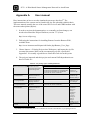
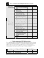
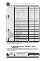
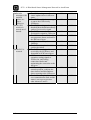
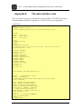
TESTING THE SYSTEM SETUP ................................................................................................... 136
TESTING SENSOR UPDATES ...................................................................................................... 137
TESTING SENSOR AND PCS-FAILURE ALARMS......................................................................... 138
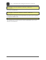
TESTING COMMUNICATION BETWEEN SCS AND MS UNDER ECS............................................ 139
APPENDIX C.
A.
B.
SYSTEM TESTING.......................................................................................... 136
DATABASE SETUP ......................................................................................... 141
THE DATABASE COLUMNS AND TYPES ..................................................................................... 141
DATABASE QUERY SENTENCES................................................................................................ 142
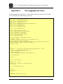
APPENDIX D.
THE SQLINTERFACE-CLASS...................................................................... 144
APPENDIX E.
THE WEB INTERFACE CODE ..................................................................... 155
APPENDIX F.
THE LOGGINGSERVER-CLASS.................................................................. 158
APPENDIX G.
STATE MACHINES......................................................................................... 160
A.
B.
C.
SCSAGENT ............................................................................................................................. 160
CSAGENT ............................................................................................................................... 164
MSAGENT .............................................................................................................................. 166
APPENDIX H.
LIST OF SIGNALS........................................................................................... 170
APPENDIX I.
IMPLEMENTATION....................................................................................... 173
vii
SCG – A Distributed Sensor Management Network in ActorFrame
viii
SCG – A Distributed Sensor Management Network in ActorFrame
List of figures
FIGURE 2-1: FACTORS AFFECTING EXPLOITABLE STOCK (REDRAWN AND SLIGHTLY MODIFIED FROM [3]) 4
FIGURE 2-2: A RIGID SEA CAGE [4]............................................................................................................ 5
FIGURE 2-3: A FLEXIBLE SEA CAGE [5]...................................................................................................... 5
FIGURE 2-4: A MOBILE FEED BARGE BY A SEA CAGE [6]............................................................................ 6
FIGURE 2-5: THE SEAWATCH SYSTEM OVERVIEW [9] ............................................................................... 7
FIGURE 2-6: RADAR IMAGES USED FOR DETECTING AND POSITIONING FISH CAGES [10]............................ 8
FIGURE 3-1: AN OVERVIEW OF THE SEA CAGE GATEWAY-SYSTEM ELEMENTS [1] .................................... 9
FIGURE 3-2: COMMUNICATION SCHEMES OF THE SEA CAGE GATEWAY .................................................. 10
FIGURE 3-3: THE DRIFTING BOUNDARIES FOR A SEA CAGE ...................................................................... 12
FIGURE 4-1: THE AKVASMART AKVASENSOR CAMERA - SMARTEYE [13]............................................ 15
FIGURE 4-2: THE AKVASMART AKVASENSOR VICASS BIOMASS ESTIMATOR [14] ................................ 15
FIGURE 4-3: THE AKVASMART AKVASENSOR OXYGEN [15]................................................................. 15
FIGURE 4-4: A SENSOR NETWORK [17] .................................................................................................... 16
FIGURE 4-5: THE GENERALIZED CONCEPT OF SENSOR WEB [21] .............................................................. 19
FIGURE 6-1: COVERAGE MAP FOR TELENOR GPRS [25].......................................................................... 23
FIGURE 6-2: COVERAGE MAP FOR CDMA450 FOR THE PORTABLE BROADBAND MODEM [27] ................ 24
FIGURE 6-3: EXPECTED COVERAGE FOR TELENOR SEALINK [30] ............................................................ 26
FIGURE 7-1: A CLASS IN UML2.0 WITH INTERNAL STRUCTURE, PORTS AND CONNECTORS [42] .............. 29
FIGURE 7-2: ERICSSON'S DEVELOPMENT FRAMEWORK [42]..................................................................... 30
FIGURE 7-3: THE ACTOR CLASS [42] ....................................................................................................... 32
FIGURE 7-4: THE ELEMENTS OF A PLAY [42] ........................................................................................... 32
FIGURE 7-5: THE ROLEREQUEST-PROTOCOL [42] ................................................................................... 32
FIGURE 7-6: DISTINGUISHING BETWEEN DELEGATION AND BEHAVIOUR PORTS ....................................... 33
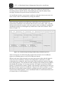
FIGURE 7-7: THE ACTORFRAME MANAGEMENT CONSOLE ....................................................................... 34
FIGURE 7-8: AN INFORMAL SEQUENCE DIAGRAM ILLUSTRATING ACTORROUTER-PROTOCOL ................. 35
FIGURE 7-9: THE WORKINGS OF ACTORROUTER ..................................................................................... 36
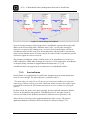
FIGURE 7-10: THE APPLICATION DOMAIN INCORPORATED BY SERVICEFRAME [45] ................................ 37
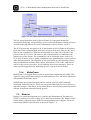
FIGURE 7-11: THE RAMSES TOOL SUITE [47]........................................................................................... 38
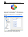
FIGURE 7-12: SCREENSHOT OF THE RAMSES MODEL VIEW IN ECLIPSE .................................................... 38
FIGURE 8-1: INTEROPERABILITY BETWEEN NODES, MOBILE GRID ............................................................ 40
FIGURE 8-2: SYSTEM CARDINALITY AND CONNECTIONS .......................................................................... 40
FIGURE 8-3: HOW THE SCG-SYSTEM IS CREATED ................................................................................... 41
FIGURE 8-4: PRELIMINARY ILLUSTRATION OF MOBILE APPLICATION INTERFACE .................................... 42
FIGURE 8-5: THE SCG-SYSTEM ELEMENTS, NODES AND DEPLOYED ACTORS ........................................... 45
FIGURE 8-6: THE SCS-ENVIRONMENT ..................................................................................................... 46
FIGURE 8-7: THE CS-ENVIRONMENT ....................................................................................................... 48
FIGURE 8-8: THE MS-ENVIRONMENT ...................................................................................................... 49
FIGURE 8-9: THE COMMUNICATION SCHEMES OF THE SCG-SYSTEM ....................................................... 51
FIGURE 8-10: A SEQUENCE DIAGRAM SHOWING FAILURE OF DIFFERENT COMMUNICATION LINKS .......... 52
FIGURE 8-11: THE SCSAGENT-ACTOR DESIGN ........................................................................................ 54
FIGURE 8-12: THE OSAPIAGENT-ACTOR DESIGN ................................................................................... 55
FIGURE 8-13: THE SENSORMANAGER-ACTOR DESIGN ............................................................................. 56
FIGURE 8-14: THE GPSSENSORAGENT-ACTOR DESIGN ........................................................................... 57
FIGURE 8-15: THE CSAGENT-ACTOR DESIGN .......................................................................................... 58
FIGURE 8-16: THE SCSMANAGER-ACTOR DESIGN .................................................................................. 59
FIGURE 8-17: THE MSAGENT-ACTOR DESIGN ......................................................................................... 60
FIGURE 8-18: THE CSMANAGER-ACTOR DESIGN .................................................................................... 61
FIGURE 8-19: THE CSSESSION-ACTOR DESIGN ........................................................................................ 61
FIGURE 8-20: THE GROUPMANAGER-ACTOR DESIGN .............................................................................. 62
FIGURE 8-21: THE INTERCOMMUNICATING ACTORS OF THE SCG-SYSTEM .............................................. 63
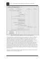
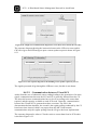
FIGURE 8-22: THE SEQUENCE DIAGRAM FOR A NEW CS REGISTERING WITH MS ..................................... 64
FIGURE 8-23: A HIGH-LEVEL COMMUNICATION DIAGRAM FOR A NEW CS REGISTERING WITH MS.......... 65
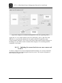
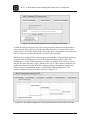
FIGURE 8-24: THE SEQUENCE DIAGRAM FOR A NEW SCS REGISTERING WITH CS.................................... 66
FIGURE 8-25: A HIGH-LEVEL COMMUNICATION DIAGRAM FOR A NEW SCS REGISTERING WITH CS ........ 67
ix
SCG – A Distributed Sensor Management Network in ActorFrame
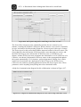
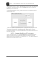
FIGURE 8-26: THE SEQUENCE DIAGRAM FOR CONNECTING A NEW SENSOR TO A SCS.............................. 68
FIGURE 8-27: A HIGH-LEVEL COMMUNICATION DIAGRAM FOR A NEW SENSOR BEING CONNECTED TO A
SCS ............................................................................................................................................... 68
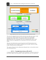
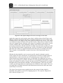
FIGURE 8-28: HOW SENSOR DATA IS RETRIEVED FROM THE NODES OF THE SCG-SYSTEM ....................... 70
FIGURE 8-29: THE SEQUENCE DIAGRAM FOR THE COLLECTION OF SENSOR DATA FROM THE MS-NODE .. 71
FIGURE 8-30: A HIGH-LEVEL COMMUNICATION DIAGRAM FOR SENSOR DATA RETRIEVAL FROM THE CSNODES ............................................................................................................................................ 72
FIGURE 8-31: THE SEQUENCE DIAGRAM FOR THE HANDLING SENSOR UPDATE REQUESTS BY THE CS...... 72
FIGURE 8-32: THE SEQUENCE DIAGRAM FOR A CS UPDATING ITS SENSOR DATA ..................................... 73
FIGURE 8-33: THE SEQUENCE DIAGRAM FOR RETRIEVING SENSOR DATA FROM A CS-NODE’S SCS-NODES
...................................................................................................................................................... 73
FIGURE 8-34: A HIGH-LEVEL COMMUNICATION DIAGRAM FOR SENSOR DATA RETRIEVAL FROM SCSNODES ............................................................................................................................................ 74
FIGURE 8-35: THE SEQUENCE DIAGRAM FOR A SCS RETRIEVING ITS SENSORS DATA .............................. 75
FIGURE 8-36: THE SEQUENCE DIAGRAM FOR INTERACTION BETWEEN THE SCS AND ITS SENSORS .......... 76
FIGURE 8-37: THE SEQUENCE DIAGRAM FOR PROACTIVE SENSOR POLLING ............................................. 76
FIGURE 8-38: THE SEQUENCE DIAGRAM FOR REACTIVE SENSOR POLLING ............................................... 77
FIGURE 8-39: THE SEQUENCE DIAGRAM FOR HYBRID SENSOR POLLING ................................................... 77
FIGURE 8-40: A HIGH-LEVEL COMMUNICATION DIAGRAM FOR ISSUING POSITION DEVIATION ALERTS .... 78
FIGURE 8-41: THE SEQUENCE DIAGRAM FOR A FAILED PCS BETWEEN A SCS AND CS............................ 80
FIGURE 8-42: A HIGH-LEVEL COMMUNICATION DIAGRAM FOR WHEN A PCS FAILS ................................. 81
FIGURE 8-43: THE SEQUENCE DIAGRAM FOR A FAILED PCS BETWEEN CS AND SCS............................... 82
FIGURE 8-44: THE SEQUENCE DIAGRAM FOR A FAILURE OF MCS BETWEEN MS AND CS ........................ 83
FIGURE 8-45: THE SEQUENCE DIAGRAM FOR A FAILURE OF MCS BETWEEN CS AND MS ........................ 84
FIGURE 8-46: THE SEQUENCE DIAGRAM FOR AN FCS-FAILURE ............................................................... 85
FIGURE 8-47: A HIGH-LEVEL COMMUNICATION DIAGRAM FOR A FAILED FCS......................................... 86
FIGURE 8-48: THE SEQUENCE DIAGRAM FOR INTERACTION BETWEEN THE SCS AND MS IN ECS-MODE . 87
FIGURE 8-49: A HIGH-LEVEL COMMUNICATION DIAGRAM FOR SENSOR REPORTING WITH ECS............... 87
FIGURE 8-50: A HIGH-LEVEL COMMUNICATION DIAGRAM FOR POSITION ALERTS WITH ECS .................. 88
FIGURE 9-1: THE MS-NODE COMPUTER................................................................................................... 90
FIGURE 9-2: THE CS-NODE COMPUTER ................................................................................................... 91
FIGURE 9-3: THE SCS-NODE COMPUTER ................................................................................................. 91
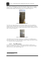
FIGURE 9-4: THE HAICOM GPS-RECEIVER .............................................................................................. 92
FIGURE 9-5: THE TELTONIKA GPRS-MODEM .......................................................................................... 93
FIGURE 9-6: THE CLASS DIAGRAM FOR LOGGINGSERVER ....................................................................... 94
FIGURE 9-7: THE CLASS DIAGRAM FOR GPSHANDLER ............................................................................ 95
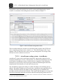
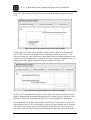
FIGURE 9-8: TELENOR GPRS HAS BEEN INITIATED ................................................................................. 97
FIGURE 9-9: THE SCG-DATABASE DESIGN .............................................................................................. 98
FIGURE 9-10: THE CLASS DIAGRAM FOR THE DBEDGESM...................................................................... 99
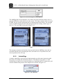
FIGURE 9-11: THE CLASS-DIAGRAM FOR SMSEDGESM........................................................................ 100
FIGURE 9-12: THE SMS-WARNINGS GENERATED FOR GPS-POSITION DEVIATION (LEFT) AND LINK
FAILURE (RIGHT).......................................................................................................................... 100
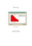
FIGURE 9-13: THE ADMINGUI .............................................................................................................. 100
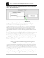
FIGURE 9-14: THE ASSIGNMENT OF THE DEFAULT GATEWAY OF ACTORROUTER .................................. 101
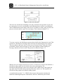
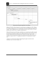
FIGURE 9-15: A SCREENSHOT OF THE SCG-SYSTEM WEB INTERFACE.................................................... 103
FIGURE 9-16: THE SCS-STATUS HAS BEEN SET TO YELLOW .................................................................. 103
FIGURE 9-17: THE SCS-STATUS HAS BEEN SET TO RED AND ECS HAS BEEN INITIATED ......................... 103
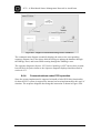
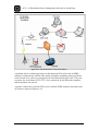
FIGURE 9-18: THE DEMONSTRATOR SETUP ENVIRONMENT .................................................................... 105
FIGURE 9-19: PICTURE OF THE TESTING ELEMENTS ............................................................................... 106
FIGURE 9-20: THE SCGSYSTEM-ACTOR DESIGN ................................................................................... 107
FIGURE 10-1: ALTERNATIVE COMMUNICATION LINKS ........................................................................... 116
FIGURE 10-2: ALTERNATIVE SCSAGENT-DESIGN ................................................................................. 117
FIGURE 10-3: THE SCSINITIATOR-ACTOR DESIGN ................................................................................. 118
FIGURE 10-4: POTENTIAL ACTORS IN AN EXTENDED SCG-DOMAIN ....................................................... 119
FIGURE 10-5: THE FORMER ENVIRONMENT FOR ACTORFRAME APPLICATIONS...................................... 123
FIGURE 10-6: THE FUTURE ENVIRONEMNT FOR ACTORFRAME APPLICATION DEVELOPMENT ................ 123
x
SCG – A Distributed Sensor Management Network in ActorFrame
List of tables
TABLE 3-1: THE ELEMENTS OF THE SEA CAGE GATEWAY SYSTEM ........................................................... 9
TABLE 3-2: THE PROPOSED COMMUNICATION LINKS OF THE SEA CAGE GATEWAY SYSTEM ................... 11
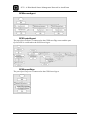
TABLE 4-1: INTERESTED PARTIES IN SENSOR DATA FROM THE SCG-SYSTEM .......................................... 19
TABLE 6-1: COMMUNICATION LINK CHARACTERISTICS AND AREAS OF APPLICATION.............................. 28
TABLE 8-1: SOME BASIC FUNCTIONAL REQUIREMENTS FOR THE SCG-SYSTEM ....................................... 43
TABLE 8-2: SOME NON-FUNCTIONAL REQUIREMENTS ............................................................................. 44
TABLE 8-3: SCS-NODE ENVIRONMENT DESCRIPTIONS ............................................................................. 46
TABLE 8-4: SCS-NODE TASKS ................................................................................................................. 47
TABLE 8-5: CS-NODE ENVIRONMENT DESCRIPTIONS ............................................................................... 48
TABLE 8-6: MS-NODE ENVIRONMENT DESCRIPTIONS .............................................................................. 49
TABLE 8-7: THE MS-NODE TASKS ........................................................................................................... 50
TABLE 8-8: SCG-SYSTEM FAILURE MODES AND CORRESPONDING ACTIONS ............................................ 52
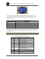
TABLE 9-1: NMEA-MESSAGES SUPPORTED BY THE GPS-RECEIVER........................................................ 92
TABLE 9-2: THE DATA OF THE GCA-MESSAGE [53] ................................................................................ 92
TABLE 9-3: TEST RESULTS AGAINST FUNCTIONAL REQUIREMENTS ....................................................... 107
TABLE A-1: SYSTEM PROJECTS WITH DEPENDENCIES ............................................................................ 133
TABLE B-1: TEST OF THE SYSTEM SETUP FUNCTIONALITY .................................................................... 136
TABLE B-2: TEST OF THE SENSOR UPDATE FUNCTIONALITY .................................................................. 137
TABLE B-3: TEST OF THE SENSOR DEVIATION AND PCS-FAILURE DETECTION AND ALARMS ................. 138
TABLE B-4: TEST OF THE SENSOR REPORTING AND ALERT GENERATION IN ECS-MODE ........................ 139
TABLE C-1: THE SCGDB-DATABASE DESIGN .......................................................................................... 141
TABLE H-1: LIST OF SIGNALS IN THE SCG-SYSTEM............................................................................... 170
TABLE I-1: THE CONTENTS OF APPENDIX I............................................................................................ 173
xi
SCG – A Distributed Sensor Management Network in ActorFrame
xii
SCG – A Distributed Sensor Management Network in ActorFrame
Abbreviations
AJAX
API
BCS
CDMA
CS
CSS
DOM
ECS
EDGE
FCS
FK
GPRS
HTTP
ICT
IM
IP
IPv6
JNI
JSP
LAN
MAC
MCS
MS
NAT
OS
PCS
PHP
PK
PPP
SCG
SCS
SDL
SMS
SOAP
SQL
TCP
TDMA
UDP
UML
UMTS
WAP
WiMAX
WLAN
WSDL
XML
Asynchronous Javascript and XML
Application Program Interface
Backup Communication System
Code Division Multiple Access
Control Station
Cascading Style Sheet
Document Object Model
Emergency Communication System
Enhanced Data for GSM Evolution
Failure Communication System
Foreign Key
General Packet Radio System
Hypertext Transfer Protocol
Information and Communication Technology
Instant Messaging
Internet Protocol
Internet Protocol version 6
Java Native Interface
Java Server Pages
Local Area Network
Media Access Control
Main Communication System
Management Station
Network Address Translation
Operating System
Primary Communication System
PHP: Hypertext Preprocessor
Primary Key
Point-to-Point Protocol
Sea Cage Gateway
Sea Cage Station
Specification and Description Language
Short Message Service
Simple Object Access Protocol
Structured Query Language
Transmission Control Protocol
Time Division Multiple Access
User Datagram Protocol
Unified Modelling Language
Universal Mobile Telecommunications system
Wireless Application Protocol
Worldwide Interoperability for Microwave Access
Wireless Local Area Network
Web Services Description Language
eXtensible Markup Language
xiii
SCG – A Distributed Sensor Management Network in ActorFrame
xiv
SCG – A Distributed Sensor Management Network in ActorFrame
“In pisciculture, as in every other form of extravagance, however, it was Lucullus
who set the most dazzling standards of notoriety. His fishponds were universally
acknowledged to be wonders, and scandals, of the age. To keep them supplied with
salt water, he had tunnels driven through mountains; and to regulate the cooling effect
of the tides, groynes built far out into the sea. The talents that had once been devoted
to the service of the Republic could not have more spectacularly, or provocatively,
squandered. “Piscinarii”, Cicero called Lucullus and Horetensius – “fish fanciers”. It
was a word coined half in contempt and half in despair.”
- excerpt from the Tom Holland book “Rubicon – The triumph and tragedy of the
Roman Republic”
xv
SCG – A Distributed Sensor Management Network in ActorFrame
xvi
SCG – A Distributed Sensor Management Network in ActorFrame
1. Introduction
In this chapter the background and motivation for this thesis are presented. In
addition, the scope of the project, its assumptions and constraints, and an outline are
given.
1.1. Background
This project is part of the Sea Cage Gateway project which is an ICT-system currently
researching the possibilites for remote control, management, and monitoring of
offshore installations in the aquaculture environment. This system is dependent on
wireless technologies to provide the connections necessary. Due to changing and
varying needs in the industry, the possibility of moving such installations from the
safe harbours of fjords and near-coastal areas to offshore locations is currently being
reviewed.
The advantages of relocating fish-farm installations offshore are many. Among these,
one can mention factors such as larger-scale production, protection of vulnerable
coastal areas, freeing up over-populated fjords, and the ability to install fish-farms in
previously inaccessible areas. This project also focuses on making such technology as
cheap and accessible as possible, allowing it to be utilized on smaller installations.
The technology and design decisions keep this in mind, maintaining a focus on nonproprietary hardware and open-source software. Low introduction costs are hoped to
make the technology easily accessible and enable many potential actors in the market.
What kinds of communication technology and system design principles are necessary
to meet the requirements needed for such a venture?
A heightened awareness to the possibilities introduced by new technology could
improve both production and add value and services to the entire value chain, giving
an edge in a competitive market. Through the coordinated use of sensors and sensor
data, production can be optimized and production costs could be reduced. An example
of this is the amount of fish feed needed. Over-feeding results in both a waste of
resources and is a source of pollution. In addition, making sensor-data available
throughout the life-cycle of a fish, control and administration can be greatly
improved.
The SCG-project incorporates a number of different areas. From the system principles
and architecture itself, to the handling of data, to the utilization of the system nodes,
to the communication technology required and so forth.
1.2. Scope
The focus area for this thesis is developing an architecture supporting the main
principles required for the Sea Cage System. This architecture is to be implemented
and demonstrated to show the principles in action. The design of the system should
allow for later extensions and utilization. The technology available to provide the
services will be briefly presented, but the demonstrator presented will be based on the
1
SCG – A Distributed Sensor Management Network in ActorFrame
available equipment. The resulting system will not be a fully-functional SCG-system,
but provide a possible basis for the development of one, either through the use of
concepts presented, or as a further development of the system itself.
The system is to be designed and implemented in the ActorFrame-framework,
utilizing the Ramses tool suite where possible.
1.3. Assumptions and constraints
The basis for the system development in this thesis is the domain descriptions
presented in the master theses “Sea Cage Gateway – Fish Farm Control Station” [1]
and “Sea Cage Gateway - Management System” [2]. Issues such as reliability and
security will not be explicitly explored; neither will the utilization of sensor data or
context beyond that of the available sensor. This thesis does not consider context and
utilization of sensor data, or how they should be administered. However, it does
consider the need for such issues, and relevant suggestions are made.
The demonstrator is restricted to the equipment available. This equipment consists of
three computers with varying characteristics, one GPRS-modem, and one GPSreceiver.
1.4. Project outline
In chapter 2, a brief introduction to the field of aquaculture is given and current trends
and related technology are presented.
In chapter 3, the Sea Cage Gateway system is presented in its current status, and the
domain that this thesis is based on is presented.
In chapter 4, sensors and sensor networks are presented. There are many similarities
between sensor networks and webs which can improve and inspire the design of the
SCG-system.
Chapter 5 presents grid computing and mobile grids. As with sensor networks, grid
computing can provide inspiration for utilizing all elements available in the SCGdomain.
In chapter 6, the communication technologies currently available for handling the
communication links of the system are presented and discussed.
Chapter 7 introduces the modelling framework that is to be used, and tools supporting
this framework.
Chapter 8 presents the system design and functionality based on a domain analysis
and the inspiration collected from the previous chapters.
Chapter 9 presents the hardware used for developing and testing the system. It
describes how specific elements of the system have been implemented, and contains a
summary of the tests conducted on the system. It also presents all the external
elements which have been included to realize the design.
Chapter 10 summarizes the experiences from deployment, and discusses design
decisions, possible extensions and features, and suggests areas of future work.
In chapter 11, a conclusion to this thesis is given.
Chapter 12 contains the references for this thesis.
In the following appendixes details of elements in the thesis are presented.
2
SCG – A Distributed Sensor Management Network in ActorFrame
2. Aquaculture
Aquaculture1 is the marine counterpart to agriculture. The principle is controlled
breeding and harvesting of marine life. Although the concept of aquaculture is not
novel, the field has undergone several major changes in the past decades. From being
a fringe industry, often used in varying forms in underdeveloped countries,
aquaculture has become an area of large social and economic focus. From feeding the
world to maintaining the coastal culture, the possibilities available through
aquaculture are many.
2.1. The history of aquaculture
The history of aquaculture goes back at least 4000 years. [3] Unlike agriculture, which
has been the main source of food for generations and partially held responsible for the
appearance of civilization, aquaculture has contributed far less to the overall food
consume. Although the principle of rearing and harvesting fish and other aquatic food
sources have been available for a considerable time, the industry has been more
concerned with improving classic hunter/gatherer techniques to obtain food from the
oceans. Reasons for why agriculture and aquaculture took such different paths are
mentioned in [3]; among those is the apparent abundance of aquatic food combined
with lacking knowledge of a foreign environment such as the marine one.
Recently the world demand for fish has superseded the amount available through
traditional capture fishery. After experiencing a steadily growing demand after World
War II, the production peeked in 2000 at 95 million tonnes. [3] Despite this, the
available amount of fish, not inluding the production in China, has not changed much
since the mid-1980s. This gap has to be covered through aquaculture fisheries, and a
prognosis yields that fish production will equal, or surpass, traditional captures fishery
production within the first quarter of the 21st century. [3]
In addition to responding to increasing demands for fish, fish production also offers a
cheaper source of vital proteins for many groups of the human population. Proteins
are a high-value source of nutrition not always easily accessible in under-developed
areas.
2.2. Factors affecting aquaculture production
There are many variables affecting the efficiency of aquaculture and the amount of
biomass that can be extracted. In Figure 2-1 the main elements and there codependencies are shown.
1
Actually, in the SCG-domain the word pisciculture would be more accurate as this relates to the
cultivation of fish. Aquaculture is a more general term, including all forms of marine life. Aquaculture
will nonetheless be used for the remainder of this thesis.
3
SCG – A Distributed Sensor Management Network in ActorFrame
Figure 2-1: Factors affecting exploitable stock (redrawn and slightly modified from [3])
As shown, there are many factors affecting the efficiency of fish-stock rearing. From
the fish are fry until they are ready for harvest, many growth environment conditions
affect their development. Improving these conditions to maximize production is of
great interest for the industries, and the use of sensor data and efficient exploitation of
them could optimize breeding conditions.
2.3. Cage techniques
The initial goal of holding fish was to keep captured stock alive until it could be sold
at the market. This was probably done through simple cages and fish traps. The actual
culture of fish, where fish were kept for longer periods of time and gained weight
have references back to the Han dynasty of China, almost 2200 years ago. [3] These
cages consisted only of cloth with bamboo sticks for support. Since then several types
of aquaculture facilities have been developed and defined. The most common types
are:
-
Enclosure is where the shoreline is the natural boundary on all sides but one.
Pen is an enclosure where all sides of the structure are man-made, except the
bottom.
Cage is an enclosure where all sides of the structure are man-made, a floating
device.
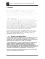
The most used in the context served in Norway, and in offshore locations, are cages.
There are several sub-categories of cages, all with different capabilities. In Figure 2-2
a rigid sea cage is shown. Rigid sea cages are, as the name implies, a rigid
construction. This gives great platform stability and easy access on onboard walkways
4
SCG – A Distributed Sensor Management Network in ActorFrame
for fish-farm personnel. Unfortunately, such construction can not withstand rough
conditions due to their stiff design.
Figure 2-2: A rigid sea cage [4]
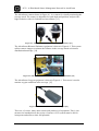
A flexible sea cage is shown in Figure 2-3. As shown, these constructions differ in
many ways from the rigid design. There is a lack of personnel access, and the
construction is not stable. Although this reduces user-accessibility, there are many
advantages with this form of design, and it is the most common construction used.
Figure 2-3: A flexible sea cage [5]
The flexibility of the design enable the construction to withstand rough conditions,
conditions often experienced in the offshore waters of coastal Norway. The
construction is also lightweight and cheap. These factors affect both the economic
side, but also allow for simpler logistics and delivery in isolated areas.
Sea cages also vary between being a floating cage or submersible. As the name
implies, a submersible cage is enclosed in all directions and can be sunk below the
seas surface when needed. This can be an advantage during rough conditions,
protecting the cage itself, the environment and its contents.
5
SCG – A Distributed Sensor Management Network in ActorFrame
Sea cages are provided feed through the use of feed barges spraying food into the
enclosure at regular intervals, or through fixed pipes mounted to the cages attached to
a central feed unit. A mobile feed barge is shown in Figure 2-4.
Figure 2-4: A mobile feed barge by a sea cage [6]
Although sea cages present a good way of rearing fish, there are problems related to
their use. Among the factors that can be considered problematic for sea cages are
currents, the spread of disease in a confined area, vulnerability to drifting objects,
fouling and wastes from fish and feed, exposure to weather and climate, ice, light,
predators/scavengers, etc. They also occupy large areas of attractive coastal areas,
may alter the behaviour of local animals, and can contribute to the spreading of sea
lice.
2.4. Aquaculture in the future
As previously mentioned there are several changes occurring within the aquaculture
industry. Previously, when production was relatively low, the rearing facilities were
few and far between. With an increase of production these facilities increased in both
size and numbers, moving from inland facilities to coastal. This represents a challenge
for the environments currently supporting aquaculture instalments. Not only will there
not be enough room in calm coastal waters, but the pressure on the local environment
will be large, depleting the conditions for not only the reared fish but also other
species dependent on the local conditions. Pollution and waste from fish farms have
already been mentioned. Larger-scale aquaculture production may also aid to relieve
pressure on over-fished populations/species, i.e. cod. With offshore production
facilities these factors can be relieved due to stronger currents, deeper waters and
space, allowing for problems experienced in coastal areas to be naturally reduced.
As a curiosity, another motivation for enabling systems for fish-farming offshore is
available in the United States of America. Here each state controls the sea out to five
miles offshore. Beyond this border, restrictions are fewer and the local authorities’
power is reduced, making it a very attractive area for producers. [7] This may not be
the most ethical reason for pursuing such a system, but it is a potential market
nonetheless.
6
SCG – A Distributed Sensor Management Network in ActorFrame
2.5. New demands from markets
With increasing focus on origin and quality of food products, new demands have
appeared for suppliers. Not only is price the main focus for the consumer, but
traceability and ecological production also influence the choice of product. This
requires efficient logging of all aspects of the aquatic products life-cycle, from the
origin of the fry, to conditions experienced during rearing, to methods used for
cultivation, etc. By efficiently logging the same factors used to optimize production
and providing traceability of fish back to a certain cage, it enables a consumer or
supplier to see what conditions the product has experienced. So the information
collected by sensors need not only be beneficiary to the producer, but also to the
market, consumer, and in research.
2.6. Current related technology used in aquaculture and
aquatic environments
There currently exist systems for monitoring fish farms and sensors specifically
designed for the purpose. A large actor in the fish-farm technology market is
AKVAsmart. [8] They offer monitoring and data analysis equipment in addition to the
sensors themselves. These systems are proprietary, and do not incorporate wireless
technologies for long-distance remote-control and administration of fish farms.
AKVAsmart are involved with the SCG-project with the intent to incorporate such
technology into their current product portfolio.
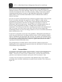
Another system using many of the same components is the SeaWatch-system. [9] The
SeaWatch-system incorporates many similar functions, only their focus is more on
marine conditions in general, rather than a sea cage specific application area. A
system overview is shown in Figure 2-5.
Figure 2-5: The SeaWatch system overview [9]
SeaWatch is an international marine surveillance and warning system, and collects
both oceanographic and metrological data. The concept of sensor data and networks
connected to autonomous systems with self-contained power supplies provides many
7
SCG – A Distributed Sensor Management Network in ActorFrame
of the same basic functions that the SCG-system will need and include. The system
uses satellite communication for its remote operations, whilst utilizing cable and
telephone lines for communication with fixed-locations installations.
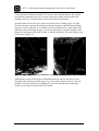
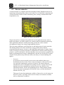
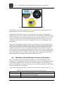
An application area for the SCG-system is the detection of drifting cages via GPS.
Projects aiming at remotely determining fish cage positions, and identifying drifting
cages have been conducted. An example is the use of Radarsat F5 (radar images) for
detecting and positioning fish cages. [10] As an alternative to satellite imagery, radar
images are not hampered by bad weather or cloudy conditions. The radar images used
are shown in Figure 2-6.
Figure 2-6: Radar images used for detecting and positioning fish cages [10]
Although the results of this project concluded that this technique did allow for the
detection and positioning of fish cages, it is a somewhat extensive process. This can
probably easily be replaced by installing GPS-recivers with adequate monitoring
systems on sea cages as part of the SCG-system.
8
SCG – A Distributed Sensor Management Network in ActorFrame
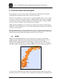
3. The Sea Cage Gateway project
The Sea Cage Gateway is a project researching how to best control and administrate
offshore and remote fish-farming facilities. The focus of the project is the use of
wireless communication technologies to provide a flexible and adaptable framework
for developing and implementing services for the system.
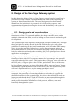
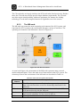
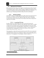
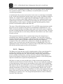
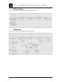
3.1. Domain description
In [1] a domain description has been provided as a basis for the system architecture.
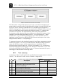
The main components of the Sea Cage Gateway system have been defined as three
main nodes, sensors, and four alternative communication schemes. A high-level
overview is given in Figure 3-1.
Figure 3-1: An overview of the Sea Cage Gateway-system elements [1]
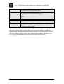
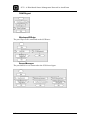
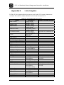
The main features are shown and described in Table 3-1.
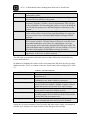
Table 3-1: The elements of the Sea Cage Gateway system
Feature
Management
station (MS)
Description
The management station is the land-based administrative station for
all control stations. All information collected by the elements in the
Sea Cage Gateway system are handled and distributed by the
management station.
Control Station The control station is the controlling agent of all the sea cages in a
(CS)
single frame. The control station administers the sea cages,
represents the frame in the system and provides, amongst other
services, the feed necessary for the fish. Sensors may be attached to
9
SCG – A Distributed Sensor Management Network in ActorFrame
Frame
Sea cage
station
(SCS)
Sensors
the control station.
The frame is a boundary around the sea cages, and keeps the cages
together whilst yielding some protection against the elements. A
frame contains up to ten sea cages all which reside under the same
control station.
The Sea Cage station is the node directly attached to each individual
sea cage. Each sea cage controls and administers the sensors
connected to it, and reports sensor data and deviating values to the
rest of the system.
Sensors form the basis of the system. All sea cages consist of a basic
array of sensors in addition to specialized sensors which are
distributed among each farm. Sensors are used to collect
information for both optimizing breeding conditions, in addition to
surveillance and control of the sea cage status.
The size of a frame is minimum 500 x 200 metres, which gives a sense of the range
communications will have to traverse. [1]
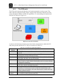
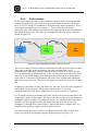
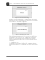
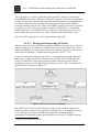
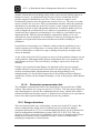
In addition to the nodes of the system, a wireless communication scheme has been
developed. It consists of two primary broadband communication links, the Primary
Communication System (PCS) and the Main Communication System (MCS),
combined with two narrowband backup systems, named as the Emergency
Communication System and the Failure Communication System (ECS and FCS).
These elements are shown in Figure 3-2.
Figure 3-2: Communication schemes of the Sea Cage Gateway
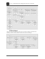
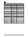
The features of the communication schemes are shown in Table 3-2.
10
SCG – A Distributed Sensor Management Network in ActorFrame
Table 3-2: The proposed communication links of the Sea Cage Gateway System
Communication
link
Main
Communication
System (MCS)
Primary
Communication
System (PCS)
Failure
Communication
System (FCS)
Emergency
Communication
System (ECS)
Description
The MCS is the primary broadband communication
technology connecting the CS to the MS.
The PCS is the primary broadband communication technology
connecting the SCS to the MS.
The FCS is a backup narrowband communication technology
which goal is to maintain communications between the MS
and CS in the event of a MCS failure. This technology should
provide other characteristics then the MCS technology.
The ECS is a backup communication system which provides
communication in the event of a failure in the PCS between
the SCS and CS. It also provides a backup in the event of a
complete communications failure in SCG, which is a
complete failure of both the FCS and PCS.
Since the backup communication schemes have different characteristics than the
primary communication technology, an extra redundancy is implemented in the
system. However, this also implies that the information flow sent in the two cases
cannot be the same. In the event of a primary link failure the system must detect this,
and adjust the data distributed to the available communication technology. An
example of this is if the ECS is the current communication link. In this case all other
communication links are down, implying an urgent need for repairs in the system. In
addition, only critical information should be broadcast over this backup link, for
instance large deviations in the position of the sea cage. Such deviations may indicate
a possible moorage breaking.
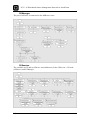
3.1.1.
Scenario
To form a basis for the system to be developed and to base some functional
requirements and design objectives on, a simple scenario has been defined. These are
based on the domains descriptions provided in [1] and have been supplemented with
the initial desired setup of such a system.
With the new low-cost SCG-system Nils Nilsen has decided to invest his life savings
into a fish farm of his own. In his remote coastal community times are hard, and jobs
even harder to come by. FishFarmAS2 already provide the MS3-node necessary for
superior administration of the system. This means that he only needs to invest in the
2
This element could also have been provided by the owner himself. It is just to show that automatic
sevice-configuration allows for many actors to be part of the SCG-domain.
3
For the remainder of this thesis the physical entity of a system element will be referred to by its
abbreviation, sometimes followed by –node. To improve readability the –node appendage will not
always be used.
11
SCG – A Distributed Sensor Management Network in ActorFrame
CS-node, frame, and SCS-nodes, in addition to providing a land-link and sea-link for
wireless communication.
After placing the nodes in their designated position the system is initiated. Upon
initiation, the CS automatically registers with the MS, and the MS-node automatically
assigns the resources necessary for administering this node, and sends the data the
CS-node needs to function optimally under current conditions. Furthermore, when
each corresponding SCS-node is connected, these also automatically register with the
CS-node, and receive correct operating parameters if necessary. The CS automatically
updates the MS with its new capabilities. Sensors which are subsequently connected
to each SCS are also automatically detected, reported and initiated for use.
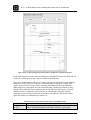
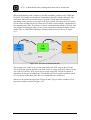
Since the system is largely autonomous, the CS needs only to be manned for a few
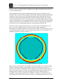
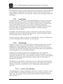
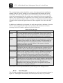
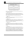
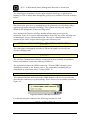
hours every day. Otherwise the system controls itself, either through selfmanagement, or through parameters sent from shore. When a SCS detects that it is out
of its default position an alarm is issued so personnel can be sent to investigate. The
boundaries for this are shown in Figure 3-3.
Figure 3-3: The drifting boundaries for a sea cage
The sea cage is represented by the meshed circle in the middle. The yellow boundary
indicates a boundary where a considerable strain on the moorings is necessary to
achieve such a position. Within the yellow boundary is the natural position of the sea
cage, where room to move with the current and tide has been given. Finally, the red
boundary indicates that one or more moorings have broken, and that there is a
possibility of the cage being adrift. The boundaries will have to be adjusted to the
positioning of the GPS-receiver on the sea cage as it is unlikely that the receiver will
12
SCG – A Distributed Sensor Management Network in ActorFrame
be mounted in the centre. The alarm generated may take many forms and several
could be used at once. This could be e-mail, SMS, call-up function, WAP-Push,
application alarm, to mention a few.
In the event of a communication failure, the system will detects and handle the break,
and gives an alarm so a maintenance crew can be sent. Meanwhile, the system
continues to operate and monitor the fish farm taking into the consideration the new
situation the SCS-node is in.
The main keywords are self-configuration, ease-of-use, autonomy, sensor handling,
self-monitoring, and fault-tolerance.
3.2. Previous work on the SCG
As mentioned, there have been projects concerning the SCG-system previously. These
have explored and described the domain in question, and demonstrated some possible
functions. [1] proposed, and used, a client-server architecture between the nodes and
utilized Web Services for providing GPS-data reporting and handling. Another project
has considered the use of a context-manager for handling aquaculture sensor data to a
maximum degree, the so-called FiFaMos-project. [11]
13
SCG – A Distributed Sensor Management Network in ActorFrame
4. Sensors
The main building blocks of the SCG-system are the sensors mounted on the sea
cages and control station. These sensors provide the data for optimization of
production and provide the information necessary for security and maintenance
services. Handling the different sensors to perform the tasks required is a crucial goal
for a SCG-system. In addition, the type of sensors used on an installation must be
power-optimized, reliable, and robust enough to withstand the rough conditions
experienced in an offshore environment.
4.1. Sensor types
There are many different types of sensors available, all with varying detection
methods and sensor interfaces. The type of sensors can be optical, acoustic, thermal,
chemical, mechanical, electromagnetic, etc. The means of sensor data transmission
can be continuous or discrete, digital or analogue, and can require continuous
monitoring or can be handled with an interval-based polling technique. Sensors may
have some of the resources necessary to process some data or allow for a certain
degree of configuration, whilst others simply transmit a raw stream of measurements.
In general, sensors do not parse or log data, but simply read them and supply them to
a proxy for handling. [12] The proxy is generally the machine the sensor has been
connected to, and one proxy will likely administer multiple sensors.
In general, limited resources capability is an attribute to almost all sensors. This
adheres to processing power, memory, bandwidth limitation, and above all battery
capacity. Battery capacity is the limit to which all other limits succumb, with
bandwidth being the largest consumer of energy.
4.2. Sensors related to aquaculture
Sensors available for aquaculture are many, and are currently increasing. The need for
all of these sensors may not be necessary, but support for the majority should be
provided. Some of these sensors may only be needed on a simple SCS in a frame, and
this information then can apply for all SCS-nodes local to that frame.
[3] lists the following areas as of interest for utilizing sensors to detect the required
parameters; weather, current, temperature, salinity, oxygen, algae, nutrients,
biosensors, radioactivity, heavy metals, hydrocarbons, pH. In addition, sensors
monitoring the equipment in use, the food consumption and current position of the sea
cage can provide the functionality and support required. Many of these sensors can be
related to the factors influencing the exploitable stock, as shown in Figure 2-1.
Several of these sensors are available from AKVAsmart [8], and a selection of their
assortment is displayed in the subsequent figures.
14
SCG – A Distributed Sensor Management Network in ActorFrame
The AkvaSensor camera shown in Figure 4-1 is a camera for visually monitoring the
sea cage stock. The camera is adjustable for both depth and position, and provides
high-resolution video for fish and feed surveillance. [13]
Figure 4-1: The AKVAsmart AkvaSensor Camera - SmartEye [13]
The AkvaSensor Biomass Estimator equipment is shown in Figure 4-2. This system
utilizes camera images to estimate the biomass in the sea cage based on biomass
distribution knowledge. [14]
Figure 4-2: The AKVAsmart AkvaSensor Vicass Biomass Estimator [14]
The AkvaSensor Oxygen equipment is shown in Figure 4-3. This sensor is used to
monitor oxygen conditions in the sea cage. [15]
Figure 4-3: The AKVAsmart AkvaSensor Oxygen [15]
There are, of course, many other sensors and producers of equipment. This is just
meant as an introduction to the variety of sensors a SCG-system must be able to
incorporate and utilize to their full potential.
15
SCG – A Distributed Sensor Management Network in ActorFrame
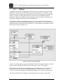
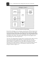
4.3. Sensor networks
A sensor network is a computer network consisting of many distributed sensors all
registering and reporting data, either to each other or to a centralized computing unit.
A sensor network consists of three elementary parts; sensing, communication and
computation. [16]
Figure 4-4: A sensor network [17]
Sensor networks are currently being utilized in several application areas, such as
traffic surveillance, air traffic control, cars, robotics and environmental monitoring.
Their application domain is steadily increasing, mostly due to the constant
development of cheap, low-energy, high-capability sensors.
There are many challenges concerning the use and deployment of sensor networks.
The limiting factors of a sensor network are energy-conservation, limited
computational and memory resources, and bandwidth requirements. In light of these
issues several types of sensor networks are implemented, with three main categories;
proactive, reactive and hybrid. [18] Note that these sensor networks are assumed to be
made up of homogeneous sensors. Although this is not the case for the SCG-system,
which will incorporate many different sensors, the theory of sensor handling still
applies.
-
Proactive
In a proactive sensor network, sensors sense and send their data at predetermined intervals of time. These sensor networks are often used in areas
were periodic examination is the area of interest. The interval between
transmissions can be manipulated according to needs. A longer interval will
translate into fewer transmissions and lower power use. However, the
information density will be correspondingly poorer. With a shorter polling
interval, the power consumption will increase, but so will the information
amount retrieved. [18]
This type of sensor data attainment could be of interest for several sensors on
the SCG-system, especially sensors used to analyze environment variables
such as temperature conditions.
16
SCG – A Distributed Sensor Management Network in ActorFrame
-
Reactive
In a reactive sensor network, sensor nodes continuously/periodically sense the
environment and transmit only information when threshold values are
violated. If the sensor data does not incriminate the pre-defined threshold
values no information is transmitted. A drawback is that sensor values are
unknown if no threshold value is broken. This method saves battery by not
transmitting information regularly, but leads to an unknown status of
environment in which the sensor is operating. [18]
Such a function could be of interest for the GPS-positioning sensor, since the
position is not of interest unless the sea cage positioning data is indicating that
the sea cage is drifting.
-
Hybrid
A hybrid sensor network incorporates elements from both the reactive and the
proactive realms. In this form the network polls information regularly, but at a
lower frequency then common in a proactive sensor network. The hybrid
network, however, also transmits data when threshold values are exceeded.
This adds flexibility to the system and incorporates the best of the other sensor
network types. Values such as polling intervals, threshold values and
parameters can all be adjusted to suit the area of application. However, this
network form is more complex, and requires more processing and bandwidth
resources, with a corresponding increase of battery power use. [18]
This type of sensor network is very versatile, allowing for both regular logging
of sensor data, whilst assurance is given that abnormal values are immediately
reported when detected. For the SCG-system this scheme could be applied to
several sensors, especially those monitoring environment variables which can
be met with counter-measures. An example of this could be a sensor
monitoring the algae-levels in the sea-cage. A complete log of the algae-levels
in the cage could be desirable for research purposes, but simultaneously,
immediate notification of hazardous levels is necessary in order to handle the
situation.
Choosing how to handle the sensors of the SCG-system depends on several factors.
What are the real-time requirements of the variable being monitored? Is it timecritical or non-time critical? What type of information is being monitored? What kind
variable is being monitored? Is the sensor attaining the values for a log, for a control
function, or both? Does battery consumption come second to attaining as much data
as possible?
4.3.1.
Mobile ad-hoc sensor networks
An extension of the standard sensor network is the mobile ad-hoc sensor network.
They are characterized by a dynamic topology and wireless communication, and
addresses how this affects sensor-handling and routing decisions. [19] The ad-hoc
connecting of sensors in a SCG-gateway environment is beyond the scope of this
17
SCG – A Distributed Sensor Management Network in ActorFrame
thesis, but issues within mobile-ad-hoc sensor networks can be applicable to the
domain in question. The main challenges with low-energy sensors in ad-hoc wireless
networks are mainly the same as in sensor networks; energy-conservation, limited
computational and memory resources, and bandwidth requirements. In addition,
mobile ad-hoc sensor networks must handle wireless communication within a
dynamic topology.
One area of research is the data-link layer utilized in a mobile ad-hoc sensor network.
Focus is on using contention-free protocols, such as TDMA, to reduce power
consumption at sensor-nodes. [19] The range a node transmits its data can also be
adjusted; ensuring that the node does not exaggerate the distance it sends its
information, thus preserving energy. Another focus area is balancing the trade-off
between sensor computations on data, or sending data to another node for
computation. The main power drain for a wireless sensor node is the transmission of
data, so in some cases a few extra cycles of the CPU uses far less energy then
transmitting the data. It is also less energy intensive to receive a wireless transmission
than to broadcast one. [18]
For the SCG-system this can provide some guidelines. Although the data-link layer
used is not part of this thesis, avoiding contention to the wireless medium could to a
degree be handled by the application. By querying, for instance, the individual SCS
one at a time in a round-robin fashion for reports contention for the wireless medium
is avoided, thus reducing interference. However, signals should still be sent when
reporting incriminated threshold values.
The routing theories of mobile ad-hoc sensor networks could be of interest for
handling inter-node communication protocols between individual SCS-nodes, but this
is beyond the scope of this thesis.
4.3.2.
Sensor Webs
An extension of the mobile ad-hoc sensor networks, a sensor web incorporates more
functionality in the sensor network, mobile or fixed. A sensor web, as defined by
NASA, “consists of a system of intra-communicating, spatially distributed sensor
pods that can be deployed to monitor and explore new environment”. [20]
A sensor web can consist of several sensors and platforms, these can be orbital
(remember, this is NASA’s definition), terrestrial, fixed or mobile. This is shown in
Figure 4-5.
18
SCG – A Distributed Sensor Management Network in ActorFrame
Figure 4-5: The generalized concept of sensor web [21]
The ability to create functioning sensor webs are due to the continuing progress of
high-performance, low-cost mobile sensor units.
Information collected by sensors are not simply sent to end users, but propagated
through the sensor web to all other integrated nodes. This sharing of information is the
source of the rich functionality achieved in a sensor web. The web itself is one of the
end users of the sensor web. Information collected and utilized by the sensor web
enables dynamic and efficient sensor configuration, sensor web management, and
adaptability.
For the SCG-system this could be of interest in many areas. If one node registers an
increase in wind speed beyond the normal values, it can alert the other SCS-nodes of
this, and these could increase the polling frequency on the GPS-position since the
weather is expected to worsen. Or an increase in algae-levels could cause all SCSnodes to increase the frequency of reading these sensors. This can also work the other
way around by reducing the polling frequency of a GPS-reciever when conditions are
calm, saving battery power. Taking it a step further, this could handle sensor loads
and configuration by adding context and load information. [12]
4.4. Utilization and distribution of sensor information
The vast amount of sensor information standing to be acquired through the widespread use of a system such as the SCG-system can be of use for many parties beyond
the fish farm company itself. Such factors can affect what type of data could be of
interest, and influence the way the sensors are set up, both in regard to the information
retrieved and the way it is handled.
Some interested parties and their possible areas of interest are listed in Table 4-1. [3]
Table 4-1: Interested parties in sensor data from the SCG-system
Party
Public authorities
Consumers
Area of interest
Authorities could follow-up on legal restrictions and laws on
fish food production and quality.
Consumers who are ecologically aware could be interested in
19
SCG – A Distributed Sensor Management Network in ActorFrame
Aquaculture
Commercial fishing
Tourist industry
Research institutes
Navy coastguard
Offshore industry
Ship traffic
tracking their fish-product to its origin and receive data on the
conditions experience by their product.
The aquaculture industry in general could collect and utilize
sensor data for research and development.
Could utilize sensor data on conditions in the offshore ocean
areas.
Weather conditions.
Oceanographic studies
Enforcement, security, rescues.
Safety
Safety. Constant updates to onboard GPS-map with the current
position of sea cages, or generating drifting sea cage alerts
could help avoid accidents.
The sensor data collected could be made available to many institutions listed in the
table above and provides a valuable basis for research and testing, in addition to
administrating and optimizing the fish farm production. As an example, the onboard
GPS-map systems of large vessels can be automatically updated on the presence of
new sea cages in addition to the position of previously deployed cages.
20
SCG – A Distributed Sensor Management Network in ActorFrame
5. Grid computing
With constantly increasing bandwidth, capacity, and connected nodes, the border
between remote and local entities are becoming blurred. The possibility of accessing
other resources on a network has led to the development of new techniques and
architectures, utilizing the availability of processing power and storage capacity. This
is often referred to as grid computing. There are many different definitions of what
grid computing really is. One definition is given by [22]:
“Grid is a type of parallel and distributed system that enables the sharing, selection,
and aggregation of geographically distributed "autonomous" resources dynamically
at runtime depending on their availability, capability, performance, cost, and users'
quality-of-service requirements.“
The utilization of resources connected to a network has been exploited in several
projects over the last decade, taking advantaged of unused capacity present on idle
connections. Large, complex tasks are split into small, independent work tasks, and
are distributed among the participants of the grid. This has been used to compute
results on protein folding, financial modelling, earthquake simulation, and climate and
environment analysis. [23]
A vision of the future of grid computing draws parallels to today’s power grids, an
inspiration which actually coined the term. Electricity is a readily available product to
an almost ubiquitous degree, and factors such as point of origin, production and
transportation methods are completely transparent to the user. The final product,
however, is a commodity. Such is the vision for processing and storage resources. In
addition, utilizing the enormous amount of latent processing power for research is an
area of many opportunities. One could eventually see all connected computer
resources as one enormous virtual computer with virtually unlimited processing
power and resources.
For the SCG-system such visions are far off. However, grid principles can be included
as to increase the power of the implemented architecture. The SCG-system will be
comprised of many sensors and many computer nodes. These elements vary in
characteristics and power. If the combined resources of these resources could be
tapped, the SCG-system could become even more autonomous. Although there are
many issues to be handled in order to utilize the resources of a distributed system, the
system design should provide a basis for providing such functionality. By building a
hierarchy of increasingly more powerful computer nodes, whilst making all nodes
aware of all other nodes, the building blocks for distributing and requesting resources
from others are laid. All nodes should have the knowledge and capability to
communicate with other nodes.
Grid computing also introduces other issues which must be attended to, such as
scheduling, and software and consistency management, but this is beyond the scope of
this thesis.
21
SCG – A Distributed Sensor Management Network in ActorFrame
5.1. Mobile Grid
Since the introduction of grid computing the network technology has been constantly
changing and improving. This has lead to two major changes. The first is the
dimension of mobility introduced by wireless communication; the other is the
abundance of heterogeneous communication links. Furthermore, the introduction of
small, handheld devices, such as the PDA and the smart phone, represent terminals
which can really appreciate the services of grid computing. Previously, the
environments for grid computing were considered relatively homogenous, stable and
centralized to a certain degree. [24] Now, even a low-end mobile phone provides at
least GSM and GPRS, often Bluetooth and IrDA, and increasingly more common, 3G
and WLAN.
With the advent of these new technologies, the extended grid, the mobile grid, poses
many challenges. The wireless communication technology is currently unreliable
compared to fixed links. The resources of the new wave of mobile terminals are very
limited compared to the standard desktop-computer. Applications aiming at utilizing
grid principles on mobile terminals must be able to handle heterogeneous network
connections with varying characteristics, different types of mobile terminal, network
disconnections, and be conscious of power consumption and battery levels. [24] In
other words applications must be terminal-aware, network connection-aware, and
power-aware.
This has many parallels to the conditions the SCG-system will experience. The SCSnodes have limited resources, both processing- and power-wise, the communication
links of the system can be of several types and characteristics, disconnections will
probably occur, mobile nodes can be introduced and there can be different operating
systems and different computers implemented on nodes. All these elements must be
considered and attended to, meaning that the system must be aware and take
advantage of them.
22
SCG – A Distributed Sensor Management Network in ActorFrame
6. Communication technologies
In this chapter a variety of the possible communication technologies for enabling
communication among the nodes in the system are presented.
UMTS is not considered as it does not have, and will not likely achieve, the coverage
necessary to offer the connections required. Although EDGE only requires an update
to current base stations, and thus in theory has the same potential coverage as GPRS,
current coverage is still poor and it is therefore not included.
GPRS, WLAN and WiMax are presented in [1] and [2], but satellite communication,
CDMA450, and VHF-Data are not. To set these technologies up against each other all
of them are presented here.
Bluetooth and ZigBee are also presented in this section. These are not alternatives for
the communication links presented earlier, but represent communication technologies
which can incorporate other functionality relative to the SCG-system.
6.1. GPRS
GPRS (General Packet Radio Service) is considered a 2.5G (G for Generation)
technology with GSM being 2G, and the aforementioned UMTS being 3G. To use
GPRS a mobile terminal or modem supporting it is required, and an operator
subscription including GPRS is necessary. GPRS provides data rates of up towards
160 Kb/s, and the coverage map for Telenor GPRS in Norway is shown in Figure 6-1.
Figure 6-1: Coverage map for Telenor GPRS [25]
As can be seen, GPRS does cover many near-coastal areas (the orange areas), and in
certain areas it also covers offshore areas, enabling the technology to be implemented
23
SCG – A Distributed Sensor Management Network in ActorFrame
at certain locations. GPRS operates on restricted frequencies and requires locally
installed infrastructure. An improvement over the traditional GSM-data is that GPRS
is packet-based and payment is for the data sent, not the time connected.
In the SCG-system, GPRS is an alternative for the narrowband ECS and FCS
communication links. The stability and latency of a GPRS-connection can be varying
and pose a challenge for the application.
6.2. CDMA450
CDMA450 is a new technology utilizing the old NMT-network in Scandinavia, and is
provided by ICE AS in Norway. [26] This service has just recently been opened for
public and commercial use, and provides services such as mobile and portable
broadband to remote districts where such services have previously been unavailable.
Due to the lower radio frequency used by this technology, the coverage is equal to, or
greater than, other comparable technologies, and the data rate is larger. The coverage
provided with the portable broadband modem is shown in Figure 6-2, and provides a
theoretical maximum capacity of up towards 2 Mbit/s.
Figure 6-2: Coverage map for CDMA450 for the portable broadband modem [27]
Although the initial data rate is larger than for instance GPRS/EDGE, the capacity is
reduced when there are many simultaneous users connected to the same access point.
As with GPRS, CDMA450 uses licensed frequencies, and require a vendor-delivered
infrastructure. In addition, the current payment model only allows up to 2GB of data
transmissions per month. [26]
CDMA450 could primarily be considered for the ECS and FCS, but with the data rate
offered, it could also function as a PCS or MCS. This is dependent on the amount of
24
SCG – A Distributed Sensor Management Network in ActorFrame
data transferred on the communication link, an amount currently difficult to predict
without further study.
6.3. WLAN
WLAN is an abbreviation for “Wireless Local Area Network”, and is the more
common term for the 802.11x standard for wireless radio communication between
nodes and access points. [28] The standard is currently available in three versions,
802.11a, 802.11b and 802.11g. The different versions operate at different frequencies
and have different range and bandwidth capabilities.
The range of a WLAN-signal from an access point depends on many factors.
Obstacles, interference and power are critical factors which determine possible range.
Range can be boosted with added power, or through the use of relay points. The data
rate for the 802.11g standard has, for instance, a theoretical maximum of 54 Mbit/s,
but in reality it operates between 10 and 20 Mbit/s.
To set up WLAN-zone for communications, one needs a wireless router/access point
and a terminal needs a WLAN client device. The client automatically detects WLAN
presence, and can automatically set up a connection if the user wishes to.
As an alternative for the PCS, WLAN is a clear potential candidate. A WLANnetwork could be installed on each sea-cage installation, with a wireless router placed
on the CS. The wireless network is easily configured and setup, data rates are high,
equipment is cheap, and it is a well-tested communication scheme. The range depends
on the equipment used and the power applied. Standard wireless routers provide up
towards 100 metres, somewhat short of what is necessary. Range can be improved by
boosting antenna power, or using relay points for re-amplifying the signal. Theoretical
tests have yielded ranges of up to, and over, several kilometres by using more
advanced antennas. The cost of such equipment is of course higher, but this can then
be utilized as the MCS as well.
WLAN is the suggested MCS and PCS of [1]. As an MCS, WLAN will quickly
become the restricting factor for how far offshore the sea cages can be placed.
6.4. Satellite communication
Satellite communication is available throughout the world, providing connectivity at
any given location. Telenor Satellite [29] provides a satellite service at sea called
SeaLink. [30] This technology can provide “always-on” internet connectivity, and
coverage is shown in Figure 6-3.
25
SCG – A Distributed Sensor Management Network in ActorFrame
Figure 6-3: Expected coverage for Telenor Sealink [30]
The SeaLink service offers data rates from 64 kb/s to 8 Mb/s. [31] Issues such as
power consumption and cost are difficult to estimate, but the range provided by
satellite communication is unmatched.
For a SCG-system incorporating such a communication technology, sea cages can be
placed almost anywhere in the world. It can function as both a narrowband and
broadband technology for the SCG-system and, in a global perspective, it is
independent of the local communication infrastructure.
6.5. VHF-Data
VHF-Data uses released frequencies within the VHF-radio system to provide a data
carrying service. Telenor Maritime Radio offer two versions of VHF-Data, a
narrowband and a broadband version. [32] The capacities are set to 21 kb/s and 140
kb/s respectively. These capacities are for compressed data, so actual data
transmission is higher, for instance it is stated that the 21 kb/s link equals a 100 kb/s
link. [33] Current coverage is the southern coast of Norway, but full coverage up to
Kirkenes is expected by the end of 2006. The system reaches up to 70 km out from
the coast. VHF-Data has always-on connectivity, and incorporates a standard
IP/Ethernet interface in the radio for simple connection to existing networks.
As VHF-data rollout has been quite recent, only time will tell how the actual
implementation works under field conditions. However, it is absolutely as an
interesting candidate for providing ECS and FCS connections.
6.6. WiMAX
WiMAX is the more common name for the 802.16 standard and is an acronym for
“Worldwide Interoperability for Microwave Access”. It is generally considered as a
future wireless alternative to cable and DSL. The technology provides a range of up to
26
SCG – A Distributed Sensor Management Network in ActorFrame
50 km, with a theoretical data rate of 70 Mb/s, but more likely between 500 kb/s to 2
Mb/s. [34]
WiMAX delivers great range and great capacity, a combination which is unmatched.
This technology would be a natural choice for the MCS of the SCG-system.
It should be noted that field tests in Chile with WiMAX transmissions over the ocean
surface have not been promising. The links are very unstable, which to a large degree
is due to transmission interference because of reflection of the signals from the sea.
These factors can also affect the range of the similar WLAN-technology. An
improvement has been achieved by placing the transmitting and receiving antennas
higher up in the air, thus changing the angle of which the radio waves hit the sea
surface. [35]
6.7. Bluetooth
Bluetooth is a wireless radio standard with focus on low energy consumption. It
currently exists in three standards, with communication ranges from 10 cm up to 100
metres, and it can support communication speeds up towards 2.1 Mbit/s. It is able to
discover other Bluetooth units in their vicinity through the use of a Service Discovery
Protocol. [36] Whilst WLAN is considered a wireless version of wired Ethernet
LAN’s, Bluetooth’s area of application has been considered to replace cables
currently used between a computer and its accessory units.
Bluetooth is included here not as an alternative for either the narrowband or
broadband communication, but because of its Service Discovery protocol. This
property is of value when it is necessary to automatically discover the presence,
services and capabilities of nodes. This could be a function to ease the implementation
of mobile nodes interacting directly with the closest SCS-node. It could also provide a
wireless connection to installed sensors. ActorFrame is currently being extended to
support Bluetooth Service Discovery and communication. [37] [38]
6.8. ZigBee
ZigBee is a relatively new wireless communication technology with a focus on low
power consumption, aimed primarily at sensor applications and remote control. [39] It
is based on the IEEE 802.15.4-standard, with a theoretical range of up to 100 metres.
The bandwidth is set to be between 20 and 250 kb/s. As for the battery lifetime, this
can be from several hundred days, to over one thousand. [40]
ZigBee nodes can automatically construct ad-hoc networks upon need, using an AdHoc On-demand protocol.
This technology could be used to allow for wireless connections of sensors to an SCS,
enabling the entire Sea Cage Gateway System to be wireless.
27
SCG – A Distributed Sensor Management Network in ActorFrame
6.9. Summary
The main characteristics of the communication technologies currently available are
shown in Table 6-1. The licensed spectrum column implies whether an existing
infrastructure is necessary by vendors with license permissions, which can translate
into a cost-penalty on the amount of data transmitted. Elements such as range and data
rate are difficult to pinpoint exactly. Varying environments and elements can greatly
alter these characteristics, and field tests are probably necessary to establish correct
parameters.
Table 6-1: Communication link characteristics and areas of application
Communication
technology
Range
Licensed
spectrum
MCS PCS ECS FCS
GPRS
High
YES
No
No
Yes
Yes
CDMA450
WLAN
WIMAX
VHF-Data
High
Low
Medium
High
YES
NO
YES
YES
Yes
Yes
Yes
Yes
No
Yes
Yes
No
Yes
No
Yes
Yes
Yes
No
Yes
Yes
Satellite
communication
Global
YES
Yes
No
Yes
Yes
Data
rate
(max)
160
kb/s
2 Mb/s
20 Mb/s
2 Mb/s
140
kb/s
8 Mb/s
When considering the suitability of a communication technology to the requirements
of the four links defined for the SCG-domain, range and data rates are the most
obvious characteristics. The PCS requires least range, but may require larger capacity
due to the amount of communicating nodes present. The ECS requires the largest
range of all. This is not only because it is the element farthest from land, but because
it must also provide communications in the case of a moorage breaking. This can
quickly bring the sea cage far out to sea. The FCS and MCS are supposed to cover the
same distance, assuming that the CS-node, the frame, and all the SCS-nodes do not
begin to drift.
Most technologies are easily interconnected with WLAN through an Ethernetconnection. For PCS, WLAN is the obvious choice. For the other connections there
are no clear technologies which stand out above the rest. In addition, several more
factors about the data rate, capacity and latency requirements of the SCG-system must
be determined. As the ECS, satellite communication may be the best alternative due to
the possible drifting of sea cages. For MCS perhaps CDMA450 is the preferred
choice, with FCS being VHF-Data. In time, WiMax should be able to compete as
being the primary choice for MCS.
28
SCG – A Distributed Sensor Management Network in ActorFrame
7. Framework and modelling concepts
In this chapter the ActorFrame-framework and adhering concepts are introduced.
UML2.0 is presented as this is the modelling language used by ActorFrame. UML2.0
is also used for implementing the design into the Ramses tool suite, also presented in
this chapter.
7.1. UML2.0
UML2.0 is the modelling language used for Ericsson Service Development
Framework presented in the following sections. UML is defined for object-oriented
development processes in [41] as:
“The Unified Modelling Language (UML) is a general-purpose visual modelling
language that is used to specify, visualize, construct, and document the artefacts of a
software system.”
UML2.0 is the continuance of UML, and addresses the problems and shortcomings of
the previous standard. It also represents a convergence between computer and
telecommunication architectural concepts. Several of UML2.0 concepts are used for
modelling ActorFrame-based applications. The most relevant elements are listed in
[42]. These are Parts, Ports, Connectors, State Machines, Composite State and
Profile.
UML2.0 captures both the static structure of the system and its dynamic behaviour.
7.1.1.
Inner structure
In UML2.0, the definition Part enables the description of the internal structure of a
class. A part can contain other parts, and may create and kill inner parts during its
lifetime. Parts have multiplicities in the form [n…m]. A class with internal structure,
ports, connectors and multiplicities is shown in Figure 4-2.
Figure 7-1: A class in UML2.0 with internal structure, ports and connectors [42]
Ports define a formal connection between parts, and can provide an interface between
the class and the environment. Ports can either be directly connected to its part, or
delegate signals to inner parts. These are known as behaviour ports and delegation
29
SCG – A Distributed Sensor Management Network in ActorFrame
ports respectively. [42] Unfortunately, these do not have separate notations in
UML2.0.
Connectors specify links between parts to enable communication. They can either be
connected to a port, or directly to a part. [42] When a connector is connected directly
to a part from a port, a form of one-way communication arises. The part with the port
may send a signal to the connected part, but the connected part cannot utilize the
connector to specify a receiver. To respond it must use a specific address or answer to
the signals originator.
Profiles can be used to make new concepts for a model. In ActorFrame the stereotype
<<Actor>> is used on parts. The extensions of this can only be applied on instances of
the metaclass Actor. [42]
7.1.2.
State machines
UML2.0 offers increased support for modelling state machines and the encapsulation
of behaviour in composite states. State machines function by accepting triggers in
states, performing an action, and then changing states. Sometimes a state change
results in the previous state. Triggers can be messages, timeouts, value change, or
procedure calls. [42]
7.2. Ericsson’s service creation architectures
ActorFrame is a Java framework providing a high level of abstraction for creating
services. It is part of Ericsson’s development framework, shown in Figure 7-2, and is
based on UML2.0 modelling concepts for inner structure and state machines.
Figure 7-2: Ericsson's development framework [42]
The main motivation of these architectures and frameworks is to release the designers
from the trivial tasks of handling non-service specific technicalities, allowing them to
focus fully on service functionality. [42]
As is shown in the figure, ActorFrame is based on JavaFrame, and provides support
for the higher levels of abstraction of ServiceFrame.
30
SCG – A Distributed Sensor Management Network in ActorFrame
The frameworks build on concepts familiar from telecom-domains, with terminals and
users wishing to communicate with each other. In such a sense, the SCG-system is
slightly different, but that does not mean that it cannot provide modelling concepts for
this domain..
7.2.1.
JavaFrame
JavaFrame provides a framework for implementing UML2.0 concepts, such as state
machines and composites, in Java. It also offers asynchronous message passing in
Java. By providing predefined classes for UML2.0 design concepts, a model can be
directly implemented using Java. It also supports asynchronous messaging,
mechanisms such as identifying the sender of signals, and applies the save concept
known from SDL. By using an underlying Scheduler, JavaFrame simulates
concurrency of Active objects.
It should be noted that the state machines of JavaFrame can only trigger transitions
through the reception of signals (this includes timers), and does not support triggers
such as changed values or method calls. [42]
The main classes provided in JavaFrame are StateMachine, Composite and Mediators.
For more information about JavaFrame, see [43] and [44].
7.2.2.
ActorFrame
ActorFrame is based on the JavaFrame-framework which, amongst others, provides
support for message-passing and state machines. ActorFrame incorporates rolemodelling for creating applications, based on the concepts of roles, actors and plays.
ActorFrame also provides distribution functionality which enables easy distribution of
actors through the use of an ActorRouter-instance.
In addition to providing a framework for modelling services, the ActorFrameframework provides possibilities for easy modularity. With state machines as a core
component, distribution is easier, and verification is simpler to achieve, both manually
and with tools supporting such functionality. It also provides a certain degree of
structural documentation.
The Ramses tool-suite allows for model driven service engineering with ActorFrame
and provides automatic code generation from models. It also supplies trace functions,
and input consistency check functions, and is continuously being extended and
improved.
7.2.2.1. Actors, roles and plays
The building block of a play in ActorFrame is the actor. An actor is in essence a statemachine capable of receiving and sending actor messages, and can contain several
inner actors. The structure of an actor in ActorFrame shown in UML2.0 notation is
shown in Figure 7-3.
31
SCG – A Distributed Sensor Management Network in ActorFrame
Figure 7-3: The Actor class [42]
The basis for ActorFrame-modelling is the play-annotation incorporated. A play can
be compared to a service, provided by actors playing roles to achieve a performance.
These collaborations last as long as the service is needed. As with a play, an actor can
play several roles and be a part of several plays. This is shown in Figure 7-4.
Figure 7-4: The elements of a play [42]
To set up a service, the RoleRequest-protocol provided by the framework is used. This
consists of a RoleRequest-message sent to the actor incorporating the role required.
This can either be the actor itself, or from one of its inner actors. If the role can be
performed, a RoleConfirm-message is sent to the originator of the RoleRequestmessage, and the role can be used. The protocol is shown in Figure 7-5.
Figure 7-5: The RoleRequest-protocol [42]
When a role is no longer necessary in a service, or the service itself is discontinued, a
RoleReleaseMsg-signal can be issued to the actors participating. The
RoleReleaseMsg-message removes not only the actor which receives the signal, but
any other actors who have been request by that actor, and so on. The response to a
RoleReleaseMsg-signal is RoleRemovedMsg-signal.
As mentioned in section 7.1.1, UML2.0 does not provide separate notations for
behaviour and delegation ports. In this thesis, however, behaviour ports will be
32
SCG – A Distributed Sensor Management Network in ActorFrame
symbolised with a white square, whilst delegation ports are shown with filled (black)
squares. This is shown in Figure 7-6.
Figure 7-6: Distinguishing between delegation and behaviour ports
The filled port indicated by the green arrow is a delegation port enabling the
InnerMostActor-actor to connect directly to the OtherActor.
The full functionality of ports is somewhat unclear in ActorFrame. What kind of
behaviour occurs when several instances are connected to same port is uncertain.
Therefore ports in this system are only used in one-to-one relationships of static
actors, and only connectors are used when connecting a dynamic instance to a static
actor.
In the SCG-system the service-modelling through the use of the play-analogy may not
be all that obvious. Mainly, the RoleRequest-protocol is intended to be used to
provide a level of self-configuration of the nodes in the system. Actors will represent
entities of the system, and interact to provide the services required by the system
through signal-passing and by dynamically adding and removing actors and roles. The
plays will largely consist of interacting actors placed on the nodes of the system. The
framework provides the addressing, ports and connectors used for the system and
handles message passing.
7.2.2.2. ActorFrame standalone app and management
console
An ActorFrame standalone version has been released to enable quicker development
and execution of services. In essence, this implies that developers do not have to use
J2EE servers to execute services. This is an advantage, as dealing with J2EE servers
can be a quite complex and heavy process. [42] It should be noted that one can switch
to a J2EE platform at a later stage. [42]
ActorFrame also provides a management console which can be initiated upon service
execution. The management console provides many options, from requesting the state
of any actor, to the sending of any signal available in the system. In this project the
33
SCG – A Distributed Sensor Management Network in ActorFrame
management console has mainly been used for testing and debugging the system
created. A screenshot of the management console is shown in Figure 7-7.
Figure 7-7: The ActorFrame management console
This screenshot shows the creation of a RoleRequestMsg-signal to the SCGSystemactor, requesting a CSAgent-actor, named “csa”. The current status of the “/scgs”instance of the SCGSystem-actor can be seen in the background. The design of the
SCGSystem-actor is shown in section 9.5.
7.2.2.3. ActorFrame routing system - ActorRouter
ActorRouter4 is part of the ActorFrame-framework, and provides support for the
transparent distribution of actors. Unfortunately, no official documentation currently
exists on how ActorRouter works or which services it supplies, so the following
description is given strictly from observing its behaviour and through a black-box
interpretation (with elements of a trial-and-error process).
The ActorRouter requires the setting of a public IP address and a default gateway
address. The public IP address is necessary since ActorRouter uses application-level
routing. This implies that the IP-address of the sending party is included in the
messages and not read from the IP-header. This requires that designers (or users) must
have more knowledge about their network connection and topology than usual. For
4
ActorRouter is sometimes referred to as Actor router. In this thesis it has been named ActorRouter so
it is not to be confused with Router-actors.
34
SCG – A Distributed Sensor Management Network in ActorFrame
instance, if one is residing behind a NAT with private addresses, then the portforwarding scheme must be known. The default gateway is the IP-address where
messages-recipients not present on the local node are sent.
An ActorRouter-instance, upon request, resides on each node where actors exist. An
actor is made visible to ActorRouter by calling the method:
setVisible(true);
in the actors state machine (ActorSM-class), which allows for a local actor to be
registered by ActorRouter. The default is that an actor is not visible. After a set time
interval (by default, 40 seconds), each actor reports to their ActorRouter, and then the
ActorRouter reports to a default gateway which actors reside on its domain. This is
shown in Figure 7-8.
Figure 7-8: An informal sequence diagram illustrating ActorRouter-protocol
After receiving the ActorRouterRegMsg-signals from all actors, the ActorRouter
reports to its default gateway every ten seconds (not shown).
When a local actor sends a message to an actor not present on the node the signal is
sent to the local ActorRouter. Here the forwarding table is checked to see if the
recipient has been registered, and if not present, than ActorRouter sends the message
to its default gateway. The ActorRouter-table residing on the default gateway address
then handles the message. If it is not present here, the signal is resent to its default
gateway. Eventually the recipient is found, or the message is discarded. No notice of a
discarded message is given by ActorRouter. The process is shown in Figure 7-9. Note
that the process presented assumes that the residing actors on a node have not been
reported to the default gateway, so the ActorRouter-table of ActorDomain B does not
yet contain those of ActorDomain A.
35
SCG – A Distributed Sensor Management Network in ActorFrame
Figure 7-9: The workings of ActorRouter
Upon receiving messages from foreign actors, ActorRouter registers their origin and
adds it to the local routing-table. When the actor “a@c” receives the message in
action six, it replies to the sending actor. As can be seen from the figure, the local
ActorRouter now has this actor in its forwarding table, and the signal is sent directly
to the correct domain (action 8). These entries are removed after a certain time-period
if no more signals are sent or received.
The messages sending the visible, resident actors of an ActorRouter are sent over a
UDP-connection, whilst other messages are sent over a TCP-connection. ActorRouter
is currently being extended to support Bluetooth interaction. [37] [38]
ActorRouter does not support ports or connectors over distributed entities.
7.2.3.
ServiceFrame
ServiceFrame is an application of ActorFrame, designed to increase the abstraction
level of service design. The main objective, as stated in [45] is:
“The main objective of the ServiceFrame project has been to address the principal
underlying problems seeking to provide sound and viable solutions that enable rapid
development of advanced, hybrid and personalized services without sacrificing the
quality.”
In other words, the goal is to be able to design, develop and offer advanced, hybrid
services in the shortest time possible. With hybrid services, the paper refers to
services provided across different networks by different service providers. [45]
This is done by focusing on the application domain of the service. The generic
application domains considered in ServiceFrame are shown in Figure 7-10.
36
SCG – A Distributed Sensor Management Network in ActorFrame
Figure 7-10: The application domain incorporated by ServiceFrame [45]
The key design principles used for ServiceFrame are conceptual abstraction,
environment mirroring, role modelling, service-centred architecture and the use/reuse
of frameworks and patterns. For more information on ServiceFrame, see [45].
The SCG-system may not appear to be in the domain of ServiceFrame at first glance.
How can a sensor administration and retrieval system fit in here? Who are the users?
Who are the communities? What are the terminals? In a sense, all of the above are
present in the SCG-system. The users are the nodes themselves, in addition to the
human users of the system. The communities can be all similar nodes; such as all
SCS- and CS-nodes, local or global, in addition to the administration, rescue teams or
other interested parties. The terminals are the node-hardware and operating systems,
and user-introduced elements (PDA, laptop, smart phone). The nodes, with sensors,
can be seen as service providers, service enablers and service cutsomers. These are
some possible suggestions for modelling the SCG-system in ServiceFrame.
7.2.4.
MidletFrame
MidletFrame is a stripped down version of ActorFrame implemented in J2ME. This
opens for using ActorFrame concepts on small mobile devices, and allows interaction
with standard ActorFrame actors.
MidletFrame incorporated on smart phones could be used for mobile terminals
interacting with nodes on site. These can incorporate Bluetooth for service discovery
and node presence. This allows for the smart phone to directly and seamlessly interact
with the ActorFrame-elements already present.
7.3. Ramses
Ramses is a system development tool, created at the Department of Telematics at
NTNU. It consists of a series of plug-ins for the Eclipse platform [46]. Ramses offers
model editors, code generators, model checks and runtime trace support. The tool is
based on the UML2.0 specification, as shown in Figure 7-11.
37
SCG – A Distributed Sensor Management Network in ActorFrame
Figure 7-11: The Ramses tool suite [47]
The editor allows for the design of the system using the elements from UML2.0. The
inspectors provide means to check and validate the design. The trace viewers show
message sequences for testing and error-detection. The generator translates the system
design into code.
Ramses has been used to implement and check the SCG-system designed in this
thesis. A screenshot demonstrating the model view used by Ramses is shown in
Figure 7-12.
Figure 7-12: Screenshot of the Ramses model view in Eclipse
For more information on the Ramses system development tool, see [47].
38
SCG – A Distributed Sensor Management Network in ActorFrame
8. Design of the Sea Cage Gateway system
In this chapter the design of the Sea Cage Gateway system based on ActorFrame is
presented. First the elements, environments and task of the nodes comprising the
system are identified and described. The actual design based on the elements
identified so far in this thesis is presented, and is followed by sequence- and
communication diagrams describing the actions and functionality of the system in
different modes of operation.
8.1. Design goals and considerations
This thesis is to utilize the ActorFrame-framework for providing the desired
functionality of the SCG-system. In addition, the design considers issues such as
multiple communication links, as well as looking to sensor networks and mobile grid
for inspiration.
The system design is also inspired by many design principles listed in [48]. Although
these principles are mainly directed at the SDL-domain, they give many sound
guidelines for modelling in the ActorFrame-domain, which resembles SDL in many
ways. Among the principles followed are; describe the environment, mirror the
environment behaviour, mirror the environment knowledge, analyze the behaviour,
look for similarities, and analyse the variability. [48] These principles have all been
applied to a varying degree.
In Figure 8-1, the distribution of the different nodes is shown and how the nodes
forming the basis of the SCG-system are meant to be interconnected. An actor will
represent each node of the system. This implies that a SCSAgent5-actor will reside on
the SCS-node, a CSAgent-actor on the CS-node, and so forth. The use of the agent
name of actors is a ServiceFrame-concept, extending the actor-concept a step further.
In ServiceFrame agents are an Actor-class which publicly represents actors. Agents
automatically register themselves with a NameServer-actor for easy discovery. This
will not be implemented here, only the naming-paradigm is used.
With a basis of utilizing all the nodes in the fashion of sensor webs or in grid
computing, the possibility of connecting all nodes to each other is an option that
should be considered in the system design. The vision is that all the SCS-nodes are
interconnected through their CS, and all CS-nodes are interconnected through their
MS. The elements are not physically interconnected directly, but the connections are
made possible through the distribution of node presence, address, status and
knowledge throughout the system.
5
For the remainder of this thesis all ActorFrame-actors and signals will be represented in an italic font.
39
SCG – A Distributed Sensor Management Network in ActorFrame
Figure 8-1: Interoperability between nodes, mobile grid
To enable a scalable solution to the addressing issues, the grid/web is built up as a
hierarchy, using the natural hierarchy already implemented in the relations between
the nodes. The cardinalities of these relations are shown Figure 8-2.
Figure 8-2: System cardinality and connections
40
SCG – A Distributed Sensor Management Network in ActorFrame
Here the relative connections implied by the proposed communication schemes are
illustrated. These relations have a significant influence on system design, and come up
again when analyzing the environments of the system elements.
As a basis for design, the system also assumes a certain setup sequence. As shown in
Figure 8-3, the MS-node with its MSAgent-actor is the first node to be set up. Then
the CS-node is set up, and when the CSAgent-actor is initiated it proceeds to register
itself with its MSAgent.
Figure 8-3: How the SCG-system is created
Finally, the SCSAgents are created and register with their CSAgent who, in turn,
reports the presence of a new SCS-node to its MS-node. It is therefore assumed that a
MS-node exists before a CS-node is initiated. The Register-Confirm procedure
corresponds to the RoleRequest-protocol of ActorFrame.
The SCG-system should allow for extensions to be added with a fair amount of ease,
incorporating additional services with new actors and roles. An example of this is
shown in Figure 8-4, where a mobile device receives SCG-information and could
provide control functions for the systems administration.
41
SCG – A Distributed Sensor Management Network in ActorFrame
Figure 8-4: Preliminary illustration of mobile application interface
Interaction for such an application could be achieved in a variety of ways. This
application could connect through a standard GPRS-connection to the MS-node or
connect via Bluetooth as a part of an ad-hoc network at the actual facilities (at an
SCS- or CS-node).
An alternative way of access for system interaction could be through the use of a web
browser which allows for a standard and easy way to access information. The use of
web browser interfaces is steadily increasing, with the advantage of a standardised
and highly distributed interface. However, if the user is on-location, and wishes to
retrieve information directly from a SCS or a CS, this might be impractical. This is
due to the fact that if the CS is connected via a pay per data technology this could
incur increased, and unnecessary, costs for the supplier.
Some possible functions will be illustrated in the design presented in the following
sections but will not be implemented in the demonstrator for this project. These
functions are to illustrate further areas of application, whilst the demonstrator is the
focus for the implemented elements.
8.1.1.
A basic set of functional requirements
In order to aid the design and testing process of the SCG-system, some basic
functional requirements for the system as a whole have been defined. The functional
requirements presented can also be viewed as design goals for the system. These
requirements are based on the keywords presented in the scenario in section 3.1.1, and
on the sensor network and mobile grid concepts discussed in sections 4.3 and 5.1.
These are listed in Table 8-1.
42
SCG – A Distributed Sensor Management Network in ActorFrame
Table 8-1: Some basic functional requirements for the SCG-system
R
1.
SR
a
b
c
2.
a
b
3
a
b
c
d
e
5
a
6
a
b
Description
The system must allow for automatic configuration and
registration of new nodes (CS and SCS).
The system must make information about new nodes available to
other nodes.
The new nodes must receive information about the other nodes in the
system.
The SCG-system must register all nodes.
The system must allow for information to be propagated
throughout the system.
Parameters must be available upon initiation.
Basic parameters must be possible to update upon initiation.
The system must detect and handle communication link failures.
If MCS fails between CS and MS, FCS must be used.
If PCS fails between CS and SCS, ECS must be used.
If MCS, PCS and FCS fail, ECS must be used.
Upon failure maintenance team must be notified
Upon alarms, rescue team must be notified
The system must collect and store sensor data
Data must be available for retrieval at a later occasion.
The system must utilize sensor data to issue warnings about
abnormal sensor readings.
The system must issues warnings regarding deviations in the GPSreadings against pre-defined threshold values.
The system must issues warnings regarding failed communication
links and nodes.
Priority
High
Medium
Medium
High
High
High
High
High
Low
High
Low
High
High
High
High
High
High
High
Points one and two are partly inspired by mobile grid concepts by providing all nodes
with access to all other system nodes through the distribution of address lists. Through
these lists mobile nodes can interact and gain access to the systems capabilities.
Inspiration from the sensor-network architecture is used for minimizing energy use
and resource consumption among distributed nodes, and although the utilization of
sensor data among other nodes is beyond the scope of this thesis, the architecture is to
provide a basis for incorporating the principles. These points also imply a certainlevel of self-configuration on initiation of SCG-elements
Point three deals with the fault redundancy element of the system and point four
includes the possibility of complete node failure. Point five addresses the issues of
data handling, and point six provides definitions of a few ways to handle sensor data,
slightly inspired by sensor networks.
Being only some functional requirements of a system with limited functionality, most
of the requirements have a high priority. One exception is the node-presence
distribution, as this does not directly affect the services required. They simply lay the
foundation for more advanced services. The other exception is the handling of link
failures between the CS- and MS-node. As the equipment necessary for such
43
SCG – A Distributed Sensor Management Network in ActorFrame
functionality is lacking in the demonstrator their priorities have been set to low. This
is to focus on the issues at hand with the equipment available.
This is not an exhaustive list of requirements, simply a foundation for displaying the
requirements and design goals the rest of the system can be built on and utilize. This
is the case for requirements 1 & 2 where the propagation of information and actors
provide the possibility for both self-configuration techniques and mobile-grid
functionality.
8.1.2.
Non-functional requirements
After establishing the functional requirements, the nature of the non-functional
requirements must be identified and specified. Issues such as delay, reliability, user
interaction, ease of use, cost, maintenance and more, are all aspects to be considered
when designing a system. As the system being implemented in this thesis is simply for
simulation and demonstration purposes, the non-functional requirements are often set
simply for stream-lining the test procedures. As complex a system as the SCG-system
can become, especially if providing full mobile grid computing in addition to sensor
web functionality, will inevitably provide many challenges in establishing the ideal
non-functional requirements.
Amongst non-functional requirements of the SCG-system demonstrator to be
designed and implemented, a few are displayed in Table 8-2
Table 8-2: Some non-functional requirements
Non-functional
requirement
Sensor update
interval
SCS status update
interval
CS status update
interval
PCS latency
maximum
MCS latency
maximum
PCS status check
interval
MCS status check
interval
GPS-deviation
maximum
44
Description
How often should sensor readings be performed? This will
probably vary from sensortype to sensortype and in different
scenarios. If the SCS-node begins drifting a higher frequency
for polling the GPS-receiver could be necessary.
How often should the status and sensor reports be collected
from the SCS?
How often should the status and sensor reports be collected
from the CS?
What is the maximum round-trip delay allowed for the PCSlink?
What is the maximum round-trip delay allowed for the MCSlink?
How long should it take between checking the PCS-status?
What is the maximum time window given before a reply is
required? This is again dependent on the link latency.
How long should it take between checking the MCS-status?
What is the maximum time window given before a reply is
required? This is again dependent on the link latency.
How far should a position be from a pre-defined are before
alarms are generated?
SCG – A Distributed Sensor Management Network in ActorFrame
There are many elements not listed in the table above, as the ECS- and FCS-links will
require attention in the same areas as the MCS- and PCS-links. The requirements can
also change depending of the state of the system.
The issues of privacy and security for this system have not been considered.
The purpose of this thesis is to create a demonstration of such a system. Although
non-functional requirements are an integrated part of the design, they have not been
given priority. The above discussion serves as an example of issues related to this
system.
8.2. Overview of the system elements
Before designing the actors and elements needed to provide the architecture for the
SCG-system the elements of the system must be analyzed. Determining the
environment in which a node is to operate in addition to determining its task, enables
a design which can effectively handle the scenarios expected from it. Note that there
may well be more tasks or environmental variables then those identified in the
following sections, but the system designed in this thesis will be based on the
elements presented here.
The entire SCG-system infrastructure is illustrated in Figure 8-5, and the distribution
of the agent-actors is shown.
Figure 8-5: The SCG-system elements, nodes and deployed actors
As mentioned and displayed, each node will be represented in the SCG-system with a
dedicated actor. In this thesis MCS and PCS are WLAN (LAN), and ECS is GPRS. A
FCS is not available, but design considerations do take it into account.
45
SCG – A Distributed Sensor Management Network in ActorFrame
8.2.1.
The SCS-node
The SCS-node represents the hardware on location mounted to each sea cage. This
node is directly connected to the sensors, and provides interaction with the rest of the
system through its GPRS- and WLAN-capabilities. It’s surrounding environment and
interfaces are shown in Figure 8-6.
Figure 8-6: The SCS-environment
As shown, the following elements are present in the environment for which the SCSnode must provide interaction for. They are described in Table 8-3.
Table 8-3: SCS-node environment descriptions
Environment
element
Sensors
MS-node
CS-node
SCS-node
PCS
ECS
Mobile
terminal
46
Description
Each SCS-node must provide sensor interaction and information
retrieval.
In the case of a communications failure, the SCS-node must
communicate with the MS-node directly.
Each SCS-node will have a designated CS-node to which it will report
sensor data and other relevant information.
The SCS-node may have to be aware of the other SCS-nodes under the
same CS-node to enable further functionality such as resource sharing
or additional redundancy.
The PCS must be handled by the node. This includes both the initiation
of the link, and the checking of its status.
The node must be aware of its ECS, and have the ability to initialize it
and utilize it. It must also be aware of the link characteristics, and
adjust to these accordingly. One such characteristic could be data rate,
another could be latency.
Each SCS-node should provide the possibility for a direct connection
via a mobile terminal present at the SCS.
SCG – A Distributed Sensor Management Network in ActorFrame
The communication schemes should, in essence, be transparent for the application
running on the SCS-node, and the type of communication link should only affect
which entity the node contacts (MS or CS). Unfortunately, this is not the case, as a
switch in communication link also yields a new connection with a new assigned IPaddress. Since ActorRouter uses application-level routing, this will be handled by the
node under the different failure modes. A change of communication link also leads to
a change in the recipient of signals as these are now supposed to be sent to the MSnode.
In addition to handling the environment, the node must perform a minimum of certain
tasks to ensure proper, flexible and correct operation. The minimum set of tasks
necessary for the SCS-node to perform is given in Table 8-4.
Table 8-4: SCS-node tasks
Node tasks
Parameter
storage
Description
To ensure proper operations certain parameters must be held by the
SCS-node and these must also be adjustable. These values could be
sensor-polling-intervals, threshold values etc. Each individual sensor
will also maintain a more detailed configuration set for operations.
Parameter
Elements of the data received, both from the sensors and the rest of the
control
system need to be controlled against the current parameter settings. An
example of this could be the control of current GPS-data against predetermined values based on ideal GPS-position. A breach of the set
parameters indicates a possible failure in the system, a situation
requiring immediate attention.
Data storage Sensor data retrieved must be stored for later utilization and
distribution, but not to the extent of implementing a database. Data is
ordered as they are still in the possession of their respective sensors.
OSThe system requires that the application running on each node can
manipulation interact on the operating system it resides on. Elements requiring the
use of the operating system can be, amongst others, battery-level
status, initiating/checking network connections and possibilities,
putting the system in a suspend modus for battery conservation, etc.
Sensor
In keeping with the goal of a self-configuring, self-contained system, a
Detection
separate process for checking for new sensors should be implemented.
This could also be handled by the OS-handling entity, but to focus on
the task this been kept as a separate process. Allowing sensorattachment to be a plug-and-play process in regards to the system
architecture is an important feature.
These tasks will be incorporated into the system design of the SCSAgent-actor.
8.2.2.
The CS-node
The CS-node resembles the SCS-node in many ways, and its environment is shown in
Figure 8-7. Although the functionality of different processes may vary, the basic
47
SCG – A Distributed Sensor Management Network in ActorFrame
environment and tasks are the same. The one major difference is that the CS-node
must handle all the SCS-nodes operating beneath it in the SCG-hierarchy.
Figure 8-7: The CS-environment
The handling of the SCS-nodes and the more direct connection with the MS-node are
the major extensions compared to the SCS-node. The elements present in the CS-node
environment are listed in Table 8-5.
Table 8-5: CS-node environment descriptions
Environment
Description
element
Sensors
Each CS-node must provide sensor interaction and information
retrieval.
SCS-node
The CS-node administrates and controls all SCS-nodes contained
within the frame of the CS-node.
CS-node
The CS-node may have to be aware of the other CS-nodes under the
same MS-node to enable further functionality such as resource
sharing or additional redundancy.
MS-node
The CS-node interacts frequently with the MS-node, and generated
reports and alarms are sent to this node.
PCS
The PCS must be handled by the node. This includes both the
initiation of the link, and the checking of its status.
MCS
The CS-node must also maintain and supervise the MCS-link with
the MS-node.
FCS
The node must be aware of its FCS, and have the ability to initialize
it and utilize it. It must also be aware of the link characteristics, and
adjust to these accordingly. One such characteristic could be data
rate, another could be latency.
Mobile
Each SCS-node should provide the possibility for a direct connection
terminal
via a mobile terminal present at the SCS.
48
SCG – A Distributed Sensor Management Network in ActorFrame
The CS-node tasks are largely similar to the SCS-node tasks listed previously. Besides
these, the CS-node may need to provide larger database requirements. The CS-node
may also require interoperability with more equipment, for instance the feeding
technology. For the time being this function is regarded as one of the sensors.
8.2.3.
The MS-node
The MS-node represents the main computing environment of the SCG-system, and
represents the SCG-system to the environment through a variety of interfaces. The
operating environment of the MS-node is shown in Figure 8-8.
Figure 8-8: The MS-environment
As seen in the figure, the environment of the MS-node represents many external
entities and participants. This is the main area of interaction for the SCG-system. The
elements present in the environment of the MS-node are described in Table 8-6.
Table 8-6: MS-node environment descriptions
Environment
element
CS-node
SCS-node
Database
MCS
Description
The CS-node represents a collection of sea cages, and provides the
data retrieved from these, as well as forwarding commands for the
MS-node.
Under the failure of some of the communication links, the SCS-node
will interact directly with the MS-node.
All information retrieved from all the sea cages must be systemized
and stored in a database for later retrieval and use.
Although the MS-node cannot handle any failure in a
49
SCG – A Distributed Sensor Management Network in ActorFrame
communication link, it must be aware of it so it can alert
maintenance teams.
Web server
Providing information to a web server for easy access will greatly
increase the accessibility to the system.
Administration Access to systems settings, such as for instance changing the report
frequency from the CS-nodes, must be implemented. This will give
many possibilities for fine-tuning the system, as well as defining the
correct data for group access and allowing direct interaction to the
system.
WAP/SMS/IM To provide transparent access to means of interaction with outside
actors of the system. System alerts regarding drifting sea cages can
be given to the rescue teams and administration through an SMSmessage
Groups
There are certain essential groups necessary for maintaining the
SCG-system operable. The ones shown in Figure 8-8 are the rescue
team and maintenance team. These are subsequently a sea cage
retrieval team, and a node and communication link repair team. The
right individuals must be notified for the correct incidence. This can
be achieved through the WAP/SMS previously described.
Users
Users interacting with the system either through a dedicated
application, web server or mobile terminal.
The MS-node environment could also consist of other MS-nodes, but this has not
been considered here.
In addition to handling the entities in the environment the MS-node needs to perform
additional tasks. These are similar to the ones listed earlier and are displayed in Table
8-7.
Table 8-7: The MS-node tasks
Node tasks
Parameter control
Parameter storage
Parameter settings
Data storage
Data retrieval
Warning/repair activities
Description
The node must be able to control parameters or variables
reported in to it.
Parameters for nodes must be stored in order to be
distributed to new nodes which are connected.
Centralized parameters regarding threshold values for
sensors can be one example. Another example is that of
update intervals of sensor at the SCS- and CS-nodes.
The accumulated sensor data generated by the SCGsystem must be stored for analysis and use.
The data stored must be accessible in many formats, all
providing support for both different forms of interaction
with the data, and presentation of it.
The node must provide the necessary information for
correct warning and repair activities to be initiated.
Again, this is not an exhaustive list of possible MS-node tasks, simply an example of
possible ones, and the ones used as basis for the MSAgent-actor design.
50
SCG – A Distributed Sensor Management Network in ActorFrame
8.2.4.
Failure modes
In this section different failure modes which can occur in the SCG-domain and the
related actions taken for each of them are presented. Elements that can fail are the
MCS, PCS, FCS and ECS, in addition to the failure of the nodes themselves. This is
based on the description given in section 3.1. These will be described more
thoroughly later, with sequence and collaboration diagrams when they are handled in
the system design process. The links involved and their adhering system nodes are
shown in Figure 8-9.
Figure 8-9: The communication schemes of the SCG-system
There are two ways in which a broken communication link can be detected, one from
either side of the link. In this system only one side can initiate the reserve
communication technology. If the PCS between the SCS and CS is down, only the
SCS can handle this by initiating the ECS. The CS may detect that it has lost contact
with a SCS, but can do nothing more than report this to the MS-node and request a
repair team. It is therefore important that both sides of the collaboration implement
link connectivity awareness. The above also applies for the link between the CS and
MS.
In addition to the failure of links, the nodes may also fail. This will not be considered
in this thesis, but the response will be quite similar to that of a servered
communication link, only that an additional test of node-existence is conducted.
For all signals traversing communication links, timers will be incorporated due to the
asynchronous nature of the signals. The timers can either initiate a second attempt at
sending the signal, or trigger a fail mode operation. Care should be taken and timers
should be set long enough to ensure that duplicated signals do not arrive at the
destination. Although these could simply be ignored and have no impact, there is a
possibility that duplicate signals can cause inconsistencies.
The actions taken for each scenario of a communication link failure (not the FCSfailure) are shown in an informal sequence diagram shown in Figure 8-10.
51
SCG – A Distributed Sensor Management Network in ActorFrame
Figure 8-10: A sequence diagram showing failure of different communication links
In the first alternative of the sequence diagram, a failed PCS between the SCS and CS
results in a switch to ECS and a report is made to the MS-node.
Since the communication links are in essence transparent, link failures only manifest
themselves in the system as a change of addressing the recipient of a signal. This
applies only to the SCS-node, where a primary link failure leads to an alternative
addressing node, and signals are sent to the MS-node. Another problem does arise
though. Upon initiating a new communication link, the node will receive a new IPaddress from the connection. This must also be considered, especially with the
application-level routing used by the ActorFrame ActorRouter. The actions taken
upon link failure are summarized in Table 8-8.
Table 8-8: SCG-system failure modes and corresponding actions
Failure
PCS detected
by SCS
52
Actions
ECS is initiated and the CS-node and MS-node are notified. The CSnode is notified through the MS-node. Alarms are generated.
SCG – A Distributed Sensor Management Network in ActorFrame
PCS detected
by CS
MCS detected
by MS
MCS detected
by CS
FCS detected
by MS
FCS detected
by CS
Nodes
The MS-node is notified, and alarms are generated.
Alarms are generated.
FCS is initiated and the MS-node is notified.
Alarms are generated.
The SCS is notified and ECS is initiated. SCS then notifies the MS
and alarms are generated.
A node failure will manifest as a communication link failure and be
detected through the same routines with some few additions.
When all communication schemes fail, the sea cage constellation is completely
isolated. The rest of the system will detect this, and the correct actions will be taken.
The sea cages could upon failure of all communications take turns, in a round-robin
style, registering sensor data and testing communication links. When systems are
restored the rest of the SCS-nodes return to a normal operating modus again. Such
functionality is beyond the scope of this thesis, but is an interesting area to develop
further.
8.3. Generic design of the system
Here a generic design of the system is presented and described. The implementation
will use parts of this, in addition to specialized actors of the generic concepts
presented here. An example of this will be given for the SensorAgent-actor presented
in the next section. The actors and their inner actors are shown and functionality is
presented with sequence and communication diagrams6. The bases for the design are
the elements identified in the previous chapter, combined with the functional
requirements, domain description, and sensor network and grid computing influences.
The design process has been an iterative process, with more than one change applied
during implementation. Subsequently, the designs presented have evolved compared
to the original drawings.
Several of the designs presented include elements which have not been implemented,
and are shown only to illustrate further areas of function for the SCG-system. These
functions are considered beyond the scope of this thesis or unnecessary for the
implementation of the demonstrator. Where the design differs from implementation,
the actor-name is surrounded by parenthesis and it is commented in the particular
section.
Ports and connectors have not been used between distributed actors due to the lack of
support for this in ActorRouter. As mentioned in section 7.2.2.1, ports are also used
with caution within a class.
6
UML2.0 Collaboration diagrams
53
SCG – A Distributed Sensor Management Network in ActorFrame
The Edge-appendage used on certain actors is to describe and underline that these
actors interact with elements beyond the ActorFrame-framework. These actors
provide transparency and levelling between the ActorFrame-domain and external
services.
The default ports of the actors have been omitted, as have port names on implemented
ports. The port names generally follow the naming convention “FromIdToWhoId” and
are presented with each corresponding state machine in Appendix G.
8.3.1.
SCSAgent
The SCSAgent-actor is the actor which will represent the SCS-node in the system, and
its structure is shown in Figure 8-11. Its tasks have been defined to the acquisition of
sensor data, use of certain vital sensor data (such as GPS), handle sensor data and
internal parameter settings, and maintain communications with the CS and MS.
Simultaneously, this actor runs the system, manipulates the operating system,
discovers and registers new sensors and handles eventual grid activities. This includes
not only maintaining both the available services and topology but also allowing access
to the SCSAgent from a mobile terminal. This fits in to the visions of mobile grid
presented earlier.
Figure 8-11: The SCSAgent-actor design
54
SCG – A Distributed Sensor Management Network in ActorFrame
The connected mobile terminal will then have access to all the SCS-node’s
capabilities and, if desired, the rest of the Sea Cage Gateway system. Access could for
several reasons be restricted, amongst others for security issues.
The SCSAgent-actor contains five inner actors which are:
- SCSControlAgent-actor
The SCSControlAgent-actor represents the main logic of the SCSAgent-actor.
This actor handles sensor-input, parameter distribution, and handles the
essential data from sensors such as position alerts. It also reports and answers
to its superiors in the SCG-hierarchy.
- SCSDataAgent-actor
The SCSDataAgent handles the shared, persistent data required in the SCSnode. This could be any way of storing data. It is only available through the
SCSControlAgent so that a certain level of access control can be implemented.
If necessary, this actor can function towards a database. Since only a GPSreceiver is used in this system, there is no need for a SCSDataAgent-actor for
the demonstrator, and it has therefore not been implemented.
- OSAPIAgent-actor
The OSAPIAgent-actor handles interaction with the local operating system and
provides a layer from the residing operating system and the rest of the actors.
Examples of interaction with the local OS could be to set the node to sleep, or
to obtain system information such as battery level or connection status (initiate
GPRS upon WLAN-disconnection). There should be implemented several
actors for several operating systems, a minimum for Linux and Windows. For
this system only a WindowsAPIEdge has been implemented, but other
operating system edges can easily be added. The inner structure is shown in
Figure 8-12.
Figure 8-12: The OSAPIAgent-actor design
The WindowsAPIEdge-actor is directly available to the SCSRouter through a
delegation port. The actor for the specific operating system will always
connect to this port.
-
SCSRouter-actor
55
SCG – A Distributed Sensor Management Network in ActorFrame
The SCSRouter-actor handles addressing issues for the actors of the
SCSAgent-actor. In addition to handling local addressing between actors not
connected by ports, it also handles the sending and receiving of messages to
and from the other distributed actors of the system. This provides a level of
layering between the actors of the SCS-node and those on the CS-node, MSnode and eventually the other SCS-nodes.
The advantages of having a single point of interaction with the rest of the
system are many. First and foremost, the use of a designated actor to handle
distributed communication enables an easier control of link failures. The
SCSRouter-actor uses timers for distributed communication, and can easily
discover lacking responses and hopefully take care of this. Compared to
allowing all actors control their own timers when sending messages to other
actors, this method reduces complexity but increases the workload of the
Router-actor.
- MobileTerminalAgent-actor
The MobileTerminalAgent is the terminal agent for a mobile terminal wishing
to interact with the system. This actor could function as a bridge to the CS or
MS should the native communication scheme fail. This actor has not been
implemented since it is beyond the scope of this thesis.
8.3.1.1. SensorManager
The SensorManager-actor in the system represents the sensors connected to a SCSnode. This provides a layering from the SCS to the sensors, and handles the sensors in
a dedicated process. The SensorManager-actor contains two types of inner actors, a
SensorDetectionEdge-actor and SensorAgent-actors.
The structure of the SensorManager-actor is shown in Figure 8-13.
Figure 8-13: The SensorManager-actor design
As can be seen, the SensorManager contains the following five inner-actors:
56
SCG – A Distributed Sensor Management Network in ActorFrame
- SensorDetectionEdge-actor
The SensorDetectionEdge handles new sensors connected to the system. It
listens to the communication ports and reacts when a new sensor is connected
by requesting a new SensorAgent for that specific type of sensor. The
SensorDetectionEdge-actor could, in essence, be considered to be part of the
OSAPIEdge, since it does require interaction with the residing OS. In this case,
it has been considered to be more bound to the SensorManager-actor, and has
been placed here.
- SensorAgent-actor
The SensorAgent represents the independent sensors to be supported by the
SCG-system. There will be specialized entities of this actor for each sensor
type.
- SensorControlAgent-actor
The SensorControlAgent is responsible for administering and controlling the
sensor. It can control sensor polling intervals, as well as detect sensor value
threshold deviations.
- SensorDataAgent-actor
The SensorDataAgent records data collected from the sensor. Upon request a
report can be generated from the SensorControlAgent on current and historical
status. This function is most likely to be limited to recent events due to the
restrictions imposed on the SCS-node. Logging may be only to the extent of
writing to a text-file. If the sensor does not require the storage of sensor data,
the SensorDataAgent is not needed.
- SensorEdge-actor
The SensorEdge-actor handles the direct interaction with the sensor. This
could require different types of interfaces and is separated from the rest of the
system to provide transparency.
In this system only a GPS-sensor is attached to the SCS-node. The GPSSensorAgentactor implemented is shown in Figure 8-14.
Figure 8-14: The GPSSensorAgent-actor design
As can be seen the GPSSensorAgent-actor consist only of the inner actors
GPSSensorEdge-actor and GPSControlAgent-actor. The SensorDataAgent has not
been implemented here due to the lack of need for a log of former GPS-positions. The
GPSControlAgent only compares the latest position to a default position, and reacts
only upon deviation larger than a certain pre-defined threshold. Therefore no form of
57
SCG – A Distributed Sensor Management Network in ActorFrame
data storing agent has been implemented beyond that of the latest position received
and the default position. The GPSControlAgent-actor is directly connected to the
SCSControlAgent through ports and connectors, providing a direct line of interaction
when necessary. One example is in the case of an alarm situation.
8.3.2.
CSAgent
The CSAgent-actor represents the CS-node of the Sea Cage Gateway-system. Its
structure can be seen in Figure 8-15. As earlier described, its structure and
functionality is quite similar to the SCSAgent. The actors represented in this actor are
therefore the same as for the SCSAgent-actor, although their tasks differ slightly. In
addition, the CSAgent-actor has a SCSManager-actor for administering, controlling
and interacting with the SCS-nodes deployed in the system.
Figure 8-15: The CSAgent-actor design
The CSAgent-actor consists of seven inner actors. The CSDataAgent, CSRouter,
MobileTerminalAgent, SensorManager and CSControlAgent represent the same
functions as in the SCSAgent-actor, although there features may be slightly different
or extended. The reasoning for their existence corresponds with those presented under
the SCSAgent-section. Since there are no sensors attached to the CS-node for the
demonstrator, no SensorManager has been implemented in the CSAgent.
The SCSManager is responsible for handling all SCS-nodes attached to its CS. This is
done by assigning a SCSSession-actor to each connected SCS. This is shown in Figure
8-16
58
SCG – A Distributed Sensor Management Network in ActorFrame
Figure 8-16: The SCSManager-actor design
The SCSSession-actor handles interaction with its specific SCSAgent throughout the
period the SCS is connected to the CS. This provides dedicated actors handling each
SCS connected to the CS, and provides a layer between the CS and its SCS-nodes.
8.3.3.
MSAgent
The MSAgent represents the MS-node of the system. Its structure is shown in Figure
8-17. As presented in section 8.2.3, a possible set of tasks for the MSAgent-actor have
been established. This list could of course be extended; a context handler could be
added to the system for instance. Alternatively, such functions and others could be
performed directly on the database residing on the MS-node. All of the inner actors
represent a task to be performed or interaction with the environment.
59
SCG – A Distributed Sensor Management Network in ActorFrame
Figure 8-17: The MSAgent-actor design
The MSAgent-actor initially consists of the following nine inner actors:
- CSManager-actor
The CSManager-actor is similar to the SCSManager-actor, shown in Figure
8-18 and performs the same task/role. As the SCSManager-actor, the
CSManager-actor has an inner CSSession-actor to control and interact with
each individual CS-node. The internal structure of the CSManager is shown in
Figure 8-18.
60
SCG – A Distributed Sensor Management Network in ActorFrame
Figure 8-18: The CSManager-actor design
In addition, the CSSession must be able to handle SCS-nodes when the PCS
fails. This can be done by incorporating a ReserveSCSSession-actor as an inner
actor of CSSession. This is shown in Figure 8-19.
Figure 8-19: The CSSession-actor design
When a SCS loses its connection to its CS, it requests a ReserveSCSSessionactor from its CS-node’s CSSession-actor. As there is only one SCS-node
using the ECS in the demonstrator system, the CSSession can handle the
communication for this SCS, and the ReserveSCSSession-actor has not been
implemented.
- GroupManager-actor
To handle the two essential group’s defined in [1], maintenance and rescue,
these have been assigned to the GroupManager-actor. This is shown in Figure
8-20.
61
SCG – A Distributed Sensor Management Network in ActorFrame
Figure 8-20: The GroupManager-actor design
These have not been implemented in the system as their functions have not
been completely determined.
- MSControlAgent-actor
This actor is similar to the control agents introduced in the SCSAgent and
CSAgent. This actor controls MS-necessary operations. With further research
into the workings and desired functions of the MS-node, this actor’s functions
may be distributed to other actors, or it may not be necessary at all.
- DBEdge-actor
The DBEdge-actor registers collected sensor-data and other information in a
database for storage and later retrieval.
- SMSEdge-actor
The SMSEdge provides an edge to an SMS-server for enabling the possibility
of, for instance, generating alarms to rescue groups or providing status
information. The possibility of handling incoming SMS to retrieve information
or adjust settings could also be implemented.
- WAPEdge-actor
The WAPEdge-actor provides an edge to a WAP-gateway to enable WAPspecific functions, much like those of the SMSEdge-actor. This edge has not
been implemented as the alarm function is sufficiently demonstrated with the
SMSEdge.
- httpEdge-actor
This actor holds a reference to a web-server for interaction with web-users
through a web interface. The advantages of using web interfaces for user- and
control-interaction are many. Through the use of web-pages, web-browsers
can access the information from anywhere, and to a certain extent remove the
necessity of local applications residing on user machines. To handle the
statelessness of the http-protocol, httpSession-actors are implemented as an
inner actor of the httpEdge-actor, as demonstrated in [49]. This actor has not
been implemented as this form of interaction is not the focus of the design.
62
SCG – A Distributed Sensor Management Network in ActorFrame
- AdminEdge-actor
In order for an administrator to adjust/change parameters and functionality of
the system an actor provides an edge against a user interface, most likely a
GUI. The AdminEdge is for providing an interface to system for users. In this
system it will be limited, simply providing the possibilities for testing some
functionality of the system
8.4. Sequence and communication diagrams
Here the main functionality and interaction patterns of the system are described with
corresponding sequence and communication diagrams. Not all of these sequence
diagrams have been implemented, and in some of the diagrams generic signal names
are used. This is commented in the subsequent sections. A full list of signals and
parameters can be found in Appendix H.
8.4.1.
Setting up the system
Before being able to provide the services necessary for the Sea Cage Gateway system,
the system must be set up and the nodes must be connected. The system set-up is
designed with two main objectives; the distribution of the necessary addresses for
interaction and to allow for easy configuration and set-up for new nodes attaching to
the current system. The setup also establishes the hierarchy of inter-communicating
actors. The actors involved in collaborations between the distributed nodes are shown
in Figure 8-21.
Figure 8-21: The intercommunicating actors of the SCG-system
63
SCG – A Distributed Sensor Management Network in ActorFrame
To allow for easy configuration, the SCG-system is assumed to be set-up with the
MSAgent first, with subsequent CS-nodes attaching later. This also applies to the
SCS-nodes later connected to their CS-node. This is shown in Figure 8-3. Finally,
sensors are attached to the SCS-node.
8.4.1.1. Initiating the connection between a new CS and the
MS
The first step of setting up the system is for a new CS-node to contact and register
with its MS-node. A RoleRequestMsg-signal7 is therefore sent from the CSRouteractor of the CS-node to the MSAgent inner actor CSManager and requests a
CSSession-actor to coordinate further interaction with. The sequence diagram for this
procedure is shown in Figure 8-22.
Figure 8-22: The sequence diagram for a new CS registering with MS
Upon reception of the RoleConfMsg-signal, the CSRouter-actor registers with its
designated CSSession-actor with the RegisterCSInfo-signal, a signal containing
information about the CS. In the demonstrator this signal is empty. CSSession, in turn,
adds the new CS-node to the list of current CS-nodes by sending the UpdateCSListsignal to its parent, the CSManager-actor. The CSManager-actor updates its list of
CS-nodes and sends the updated list of CS-nodes to all of its children (inner actor)
CSSessions (not shown). CSSession then forwards the list to their designated
7
Signal and message are used as synonyms in this thesis.
64
SCG – A Distributed Sensor Management Network in ActorFrame
CSAgent-actor, more precisely the CSRouter-actor which handles all communication
with higher placed nodes in the SCG-hierarchy. Finally, and if necessary, a set of
basic parameters are sent out to the CSRouter, which forwards these to
CSControlAgent-actor (not shown). This allows for basic parameter setting directly
and automatically from the MS if the default values aboard the current CS are
obsolete or unavailable. There are no such parameters included in the demonstrator.
To clearly see the messages being passed between the SCG-nodes, a high-level
communication diagram is shown in Figure 8-23.
Figure 8-23: A high-level communication diagram for a new CS registering with MS
The communication 2.1 refers to the distribution of the new, update list of CS-nodes
via the signal CSList among the CSSession-actors in the MSAgent-actor. These
sessions subsequently distribute the new list to their CS-nodes. The CSList is
distributed to the latest CS in CSSetupParameters-signal as previously shown in
Figure 8-22
8.4.1.2. Initiating the connection between a new SCS and a
CS
The procedure for connecting a new SCS-node to its CS-node, shown in Figure 8-24,
is very similar to connecting a new CS-node to the MS-node.
65
SCG – A Distributed Sensor Management Network in ActorFrame
Figure 8-24: The sequence diagram for a new SCS registering with CS
The main difference is that the SCSSession-actor reports to the CSAgent’s CSSessionactor that a new SCS-node has been installed. The SCSRouter receives a list of the
other SCS-nodes represented by their SCSRouters under the same CS-node. In
addition, the SCSRouter-actor sends a ConnectionUpdateToMS-signal to its CSAgentactors CSSession-actor. This is due to the functionality of the ActorFrame
ActorRouter. The routing table of the SCSAgent must contain the MSAgent-address in
order for messages to be sent to the MSAgent when the PCS goes down. When the
PCS is unavailable, the default gateway otherwise used is unavailable. Therefore the
SCSAgent must regularly receive messages from CSSession. This interval is specified
by the MSConnectionUpdateTimer-timer. A ConnectionCheckTimer-timer is also set;
this timer specifies the intervals in which the SCSRouter checks the PCS link-status to
the SCSSession.
A high-level communication diagram displaying messages sent between the top-level
distributed actors is shown in Figure 8-25.
66
SCG – A Distributed Sensor Management Network in ActorFrame
Figure 8-25: A high-level communication diagram for a new SCS registering with CS
Again, this is a very similar pattern as the one connecting a CS to a MS. The main
difference is, as previously mentioned, the update of the SCS-capability to the
CSAgent and the MSAgent. The ConnectionUpdateToMS-signal from the SCSAgent to
the MSAgent is not shown in this communication diagram, as it would degrade the
readability of the figure.
8.4.1.3. Initiating the connection between a new sensor and
its SCS
To achieve a high level of self-configuration and automation, new sensors should be
automatically discovered and integrated into the system. The sequence diagram for
this is shown in Figure 8-26.
67
SCG – A Distributed Sensor Management Network in ActorFrame
Figure 8-26: The sequence diagram for connecting a new sensor to a SCS
The SensorDetectionAgent-actor continually searches for new sensors by, for
instance, scanning all available COM-ports. When it detects a new sensor, it identifies
its type, and sends a RoleRequestMsg-signal for a SensorAgent for this type of sensor.
The SensorAgent for this sensor then handles input and control of the new sensor. The
SensorManager then informs the SCSControlAgent-actor about the new sensor, and
the SCSControlAgent-actor informs the SCSSession-actor (via SCSRouter, not
shown), and the SCSSession-actor propagates the information on to its CSSession (via
CSRouter, not shown). Information of the new sensor is thus propagated throughout
the system automatically. If, for instance, preferred parameter settings for a certain
sensor have been altered since deployment of the SCSAgent, the SCSSession or
CSSession can send new operating parameters back to the SensorAgent-actor. These
parameters can be anything from polling intervals to threshold values.
A high level communication diagram for this collaboration is shown in Figure 8-27.
Figure 8-27: A high-level communication diagram for a new sensor being connected to a SCS
68
SCG – A Distributed Sensor Management Network in ActorFrame
In this communication diagram, the Sensor is presented as an actor outside the system.
This is not to be confused with the actor-terminology used in ActorFrame. The
connection of a sensor generates an automatic RoleRequestMsg-signal, and the sensor
is consequently queried. The information of a new sensor is then propagated among
the nodes of the SCG-system and added to the database.
As shown in section 8.2.2, sensors may also be connected to the CSAgent-actor. This
will be handled similarly as the sequence diagram, except that it will be the CScapabilities that will be updated.
8.4.2.
Communications for sensor data retrieval under
normal operation
In the following section interaction between the different nodes under normal
operating conditions are shown. The interactions for this section have been limited to
the acquisition of sensor data from lower-level nodes. There will be other forms of
interaction during operations of the SCG-system, such as distributing new parameters
through the system, but the focus here is sensor-data-retrieval. This system only
implements timer-based sensor data collection. The discussion assumes that all
communication links are functioning properly, and that all nodes are active.
The process of retrieving sensor data has taken a two-level design. As will be shown
in the following section, each node updates and retrieves its own sensor data with predetermined intervals defined with timers. Each node also requests sensor data from a
lower-level node with a pre-defined frequency. The interval is shortest for the
SCSAgent, larger for the CSAgent and the longest interval is the MSAgents. When
receiving a query for updated sensor data, the queried node retrieves the latest data
from their data agent, and sends this to the requesting party. The principle with
involved actors is shown in Figure 8-28.
69
SCG – A Distributed Sensor Management Network in ActorFrame
Figure 8-28: How sensor data is retrieved from the nodes of the SCG-system
The reason for doing this instead of nodes retrieving sensor data upon request is both
to assure more reliable response times, since the request does not propagate
throughout the system, but also for ensuring up-to-date sensor data in each
independent node. This is important in the case of communications failure. It also
allows for data to be aggreagated at several natural levels before being reported
further.
When the sensor data has been reported upwards in the SCG-hierarchy the local
sensor data registry can be emptied, or perhaps stored in another format for backup
reasons. This has not been considered here.
The sequence diagrams for the collaborations illustrated above are described in detail
in the following sections.
8.4.2.1. Communication between MS and CS
Communications between the CS and MS can be initiated for a variety of reasons; due
to an alarm, regular sensor data update, or upon request from a user. The request can
70
SCG – A Distributed Sensor Management Network in ActorFrame
be generated either by user through the httpEdge, through the AdminEdge or through a
regular timer for retrieving the data from the SCG-system nodes. This in turn
generates a GetSensorUpdate-signal to the CSManager-actor, who proceeds to query
all its CSAgents for their sensor-data. The CSAgents are registered in a csList, which
is an ArrayList. The sequence diagram for this is shown in Figure 8-29.
Figure 8-29: The sequence diagram for the collection of sensor data from the MS-node
When the SensorDataUpdate-signal is received the signal is sent both to the
MSControlAgent-actor and to the DBEdge-actor (this is done automatically by the
MSRouter-actor). The DBEdge-actor inserts the sensor data into the database. When
all updates are finished the MSControlAgent-actor is notified of this through the
UpdateCompleted-signal, and the timer for requesting sensor updates is reset. This
timer is set for the first time when the SCG-system registers its first sensor.
A communication diagram illustrating the interactions between the distributed actors
is shown in Figure 8-30.
71
SCG – A Distributed Sensor Management Network in ActorFrame
Figure 8-30: A high-level communication diagram for sensor data retrieval from the CS-nodes
The sequence diagram showing the interaction between the CSSession-actor and its
CSControlAgent and CSDataAgent upon a sensor update request is shown in Figure
8-31.
Figure 8-31: The sequence diagram for the handling sensor update requests by the CS
The signals presented all go through the CSRouter-actor, but this is not shown.
8.4.2.2. Communication between CS and SCS
Asides from the case of abnormal sensor reading leading to the generation of an alertsignal, communications between the SCS and CS is generally initiated from the CS.
The intervals between communications have to be set according to the sensor data
required, and the capacity available on each SCS-node. Generally, communication
between the CS and SCS is generated on three occasions. The first is the
aforementioned alarm situation, the second is the regular polling conducted by the CS
based on a timer-interval, third is on request from the MS. Under normal
communications only the regular polling from the CSAgent has been implemented.
The sequence diagram for when a CS-node retrieves sensor data from its SCS-nodes
is shown in Figure 8-32.
72
SCG – A Distributed Sensor Management Network in ActorFrame
Figure 8-32: The sequence diagram for a CS updating its sensor data
As with the MSControlAgent, the CSControlAgent sensor data retrieval procedure is
timer-initiated. This timer is set for the first time when the CS is alerted of a sensor
connected to a SCS-node. When all the SCS-nodes have reported their sensor data, the
CSControlAgent is notified through the UpdateCompleted-signal.
When the SensorUpdateTimer-timer has been invoked, the CSControlAgent generates
a request to its SCSManager to retrieve the sensor data from all SCS-nodes. The
SCSManager, via the SCSSession-actors, continues to poll the SCS-nodes for sensor
data one at a time using the scsList, similar to the csList. This is both to minimize the
traffic and congestion on the PCS-link, reducing energy consumption, but this also
makes it easier to maintain the status of all link and collaborating parties. The
sequence diagram for this procedure is shown in Figure 8-33.
Figure 8-33: The sequence diagram for retrieving sensor data from a CS-node’s SCS-nodes
73
SCG – A Distributed Sensor Management Network in ActorFrame
This procedure is similar to the one where the MSAgent retrieves the sensor-data from
its CSAgents. The CSControlAgent-actor forwards the sensor data received to the
CSDataAgent-actor for storage.
A communication diagram showing the interactions between the distributed actors is
shown in Figure 8-34.
Figure 8-34: A high-level communication diagram for sensor data retrieval from SCS-nodes
This pattern is identical to the one used between the MSAgent and its CSAgents,
except there is no update to an external database here. This could be implemented at a
later stage if necessary.
8.4.2.3. Communication between SCS and sensors
A major part of this system is the acquisition, distribution and utilization of sensor
data retrieved from the sensors installed at each SCS-node. A general sequence
diagram for SCS-sensor interaction is shown in Figure 8-35. This sequence diagram is
identical for sensors attached to CS-node.
74
SCG – A Distributed Sensor Management Network in ActorFrame
Figure 8-35: The sequence diagram for a SCS retrieving its sensors data
Again, the pattern for retrieving the sensor data is similar to that of the CSAgent and
MSAgent, and the descriptions for those procedures apply here as well. An issue to be
considered here is the format of the sensor data retrieved from the sensors. One option
is to transport it in pre-defined, sensor-specific objects. These objects can preserve the
data in its original format, allowing for the data to be handled by other entities. Such a
scenario could be that of grid computing, sending sensor-data to the CSAgent for
processing and analysis. Another option is to simply report the data as a String. In this
way all sensor data could be comprised into a String, or defined in a XML-document,
and reduce the number of signals and interactions necessary for sending sensor data.
This is simpler, less bandwidth is required, but some of the data density may be
reduced.
Whether the data should be sent in a sensor-specific signal or through a generic
sensor-signal can also be discussed. It is good practice to branch on signal, and not a
signal parameter value, but in the case of incorporating new sensors in the SCGsystem using sensor-neutral signals can be an advantage. By adding the new sensordata to a pre-existing String of data, this data can easily piggyback through the system
back to the MSAgent. In such a scenario one does not have to implement a new signal
throughout the system and state machines. In the demonstrator, with only one sensor,
a sensor-specific signal has been implemented, the GPSSensorData-signal. This is an
area applicable for further discussion, and distinctions between the sensor data in the
system may be necessary.
The SensorControlAgent-actor regularly queries the sensors for data, both for
threshold-value checks, as well as for logging purposes. The sequence diagram for
this is shown in Figure 8-36.
75
SCG – A Distributed Sensor Management Network in ActorFrame
Figure 8-36: The sequence diagram for interaction between the SCS and its sensors
As shown the SensorControlAgent-actor retrieves sensor data by querying its
SensorEdge-actor for sensor data. The interval at which this happens is determined by
the timer parameters for this type of sensor. The SensorEdge-actor retrieves the
current sensor reading and sends it back to the SensorControlAgent-actor.
Alternatively the sensor data can be streamed directly to the control or data agent.
If the data is simply of interest for storage, the data is sent to the SensorDataAgent for
storage until a request for a sensor report is received, initiated through the signal
RetrieveSensorData. The required data is then sent, and if storage capacity is limited,
the current data is erased. This is similar to proactive sensor handling, described in
section 4.3. The simple sequence diagram for this is shown in Figure 8-37.
Figure 8-37: The sequence diagram for proactive sensor polling
If the sensor data is of a type that has threshold parameters concerning a range of
normal operations, SensorControlAgent-actor will compare the collected data to these
values. In the occurrence of a deviation, the SCSControlAgent is notified and
appropriate action is taken. This is similar to the reactive sensor handling, described in
76
SCG – A Distributed Sensor Management Network in ActorFrame
section 4.3. The sequence diagram for reactive sensor handling is shown in Figure
8-38.
Figure 8-38: The sequence diagram for reactive sensor polling
Finally, there is the case where the data from the sensor is both to be checked and
stored. This is similar to the hybrid sensor handling described in section 4.3. The
SensorControlAgent-actor controls the sensor data against its defined parameters and
issues an alert if the threshold is violated. If the data is within the boundaries set, it is
simply stored. The sequence diagram for this is shown in Figure 8-39.
Figure 8-39: The sequence diagram for hybrid sensor polling
In the case of a threshold-breach on received sensor data, the SensorValueDeviationsignal is automatically propagated through the SCG-system up to the MSAgent. Here
the relative alarms are issued and the status of the SCS is updated in the database.
The demonstrator to be implemented only has the use of a GPS-receiver. In the SCGsystem domain itself, GPS is used mainly to detect sea cages drifting out of position.
This would only require reactive sensor polling on the GPS-receiver to achieve its
task. But seen in the light of both context information, and other parties interested in
77
SCG – A Distributed Sensor Management Network in ActorFrame
the GPS-position of sea cages, see Table 4-1, the GPS-sensor has been implemented
with hybrid sensor polling. The generic signal SensorData has been replaced with
GPSSensorData and the SensorValueDeviation-signal has been replaced with a
PositionAlert-signal.
When the position received from the GPS-receiver violates the maximum position
deviation threshold, a PositionAlert-signal is propagated throughout the SCG-system
alerting all involved actors of the status, updating the SCS-status in the database, and
SMS-alarms are generated to the rescue team. This is shown in the communication
diagram presented in Figure 8-40.
Figure 8-40: A high-level communication diagram for issuing position deviation alerts
If wished for, the SCS could issue subsequent position alerts in pre-determined
intervals to allow for constant SMS-updates of the latest position to rescue teams
attempting to locate and salvage the fish cage. This has not been implemented in this
system, and only one SMS-warning is sent. The updated position, however, is still
reported in to the MS and is available from the database.
8.4.3.
Ensuring the detection of failures and appropriate
actions
As described in section 8.2.4, there are several modes of communication link failure
that the SCG-system must detect and handle. The system has been designed so that all
communication traversing communication links is either handled by the respective
Router-actors, or by the respective Session-actors. This reduces the number of
interacting actors over distributed links, and makes it easier to detect and handle link
failures.
When a message is sent from a Session-actor or a Router-actor a timer is set by the
entity which makes a request. All requests require a response within a pre-defined
time interval. Upon a timer-trigger the sending entity can either resend the signal or
take other appropriate actions. This could either be initiating the reserve
communication link, or issuing an alarm about a broken communication link
depending on which side of the collaboration the actor is.
78
SCG – A Distributed Sensor Management Network in ActorFrame
If the frequency of interactions between the distributed actors is rare, a heartbeat- or
hello-signal could be implemented to regularly check communication link status. If
the frequency of signal-interaction is sufficient then such a signal may not be
necessary, it would simply drain power and bandwidth.
As shown under the normal operations section, the queries are often issued from the
top-down in this system. This means that the CS requests a report periodically from its
SCS-nodes, instead of the SCS-nodes themselves initiating reports. In exception
cases, however, the SCS can send alarm messages to the MS or CS. A timer is set for
every interaction by the initiating side.
The assumption is made that the management station is under surveillance and has
backup routines for failure. The possibility that the MS fails should otherwise be
considered.
In the implementation for the demonstrator only the case of a failed PCS-link
discovered by the SCS has been implemented. Subsequently, no timers on messages
are set except for those generated periodically by the SCSAgent to check PCS-status.
The remaining sequence diagrams are suggested solutions and have neither been
implemented nor tested, but their patterns are very similar to the one used in the
demonstrator. They may function as a starting point for considering such
functionality.
8.4.3.1. Failed PCS between SCS and CS
In the event of a failure between a SCS and its CS the SCS should switch to ECS as
soon as possible. All messages sent between these entities should be replied to ensure
reception. A timer is set by the router of a SCS to ensure that missing messages are
detected. Although both the CS and SCS can detect failures, only the SCS can switch
over to ECS communication. But the CS must also be able to detect the failure, both
as to alert the MS and repair teams, but also in the event of a total failure of either the
SCS-node itself, or of the ECS. In addition, the CS must be able to maintain state
integrity when an expected signal fails to make its appearance.
The interval between the connection checks is defined as the connectionCheckTimer.
When this timer is triggered, the SCSRouter-actor sends a SCSConnectionChecksignal to its SCSSession-actor. This initiates a connectionTimer-timer which defines
the interval in which a SCSConnectionCheckACK-signal is expected to be received.
The sequence diagram for link-failure detection and handling is shown in Figure 8-41.
79
SCG – A Distributed Sensor Management Network in ActorFrame
Figure 8-41: The sequence diagram for a failed PCS between a SCS and CS
A missed receipt signal is in this case interpreted as a communication failure.
Alternatively, a failure could be interpreted as a certain number of missing receipts.
Each time the connectionTimer was received a connection counter could be
incremented, and at a certain counter value, the ECS could be assumed down. The
failure of the link could affect the report status of the control agent, but if capacity of
the new link is capable operations could continue as normal.
So if the connectionTimer expires before the SCSReportReg-signal is received, the
SCSRouter assumes that the PCS-link is down. The SCSRouter-actor subsequently
alerts the SCSControlAgent-actor of the failed link so it can adjust to the new status
(shown later). SCSRouter-actor also sends a request to the OSAPIEdge-actor to
initiate the reserve communication link through the signal InitEcs. Upon confirmation
that the ECS has been initiated, SCSRouter sends the SCSPCSFailed-signal to its CSnode’s CSSession, alerting that the PCS has failed. The CSSession-actor can then
handle the further situation by both being a recipient of alarms from the SCS, alerting
the SCSSession of the CSAgent, updating the database status and alerting the proper
personnel to ensure swift repairs.
80
SCG – A Distributed Sensor Management Network in ActorFrame
The messages exchanged between the distributed actors are also shown in the
communication diagram presented in Figure 8-42.
Figure 8-42: A high-level communication diagram for when a PCS fails
In the implementation the CSSession-actor handles all SCS-nodes under their CSnode when the PCS is down. As suggested in section 8.2.3, a ReserveSCSSession
could be initiated to handle each SCS in ECS-status
The other possible scenario, the case of a detected failure from the CS side of the
collaboration, is handled somewhat differently. The sequence diagram for this is
shown in Figure 8-43.
81
SCG – A Distributed Sensor Management Network in ActorFrame
Figure 8-43: The sequence diagram for a failed PCS between CS and SCS
The SCSRouter-actor is the recipient of the GetSensorUpdate-signal generated by its
corresponding SCSSession-actor. Since there is only one SCSSession per SCS, it is
simpler to handle link failures due to the one-to-one relationship of intercommunicating actors.
If the connectionTimer expires before the GPSSensorData-signal is received the link
between the CS and SCS is assumed to be down. The SCSSession report a link failure
to the CSControlAgent, who in turn, via CSRouter, alerts its CSSession. The
CSSession can then generate the alarms necessary to the correct personnel.
8.4.3.2. Failed MCS between CS and MS
In the event of a MCS-failure between the CS and MS, events are much similar to
those of a failure between a SCS and its CS. The difference is that the recipient of the
messages is still the same, meaning that the messages are still sent to CSSession. The
sequence diagram for this scenario is shown in Figure 8-44.
82
SCG – A Distributed Sensor Management Network in ActorFrame
Figure 8-44: The sequence diagram for a failure of MCS between MS and CS
When the MS detects a failed communication link to a CS, it can do little more than
alert the correct personnel about the failure. In order to restore communications the
CS must itself become aware of the link failure and switch to FCS-communication.
This is shown in Figure 8-45.
83
SCG – A Distributed Sensor Management Network in ActorFrame
Figure 8-45: The sequence diagram for a failure of MCS between CS and MS
As previously mentioned, the procedure here is very similar to when a SCS switches
to ECS. Here the initiation of the GPRS-link is done (if the FCS is GPRS), and a
report of the situation is sent to the MS-node’s CSSession, which will then take the
appropriate measures for re-establishing the link.
8.4.3.3. Failed FCS between CS and MS
Another scenario is that of the FCS failing. If this happens the SCS-node must be
alerted so it can initiate ECS to preserve communication capabilities until the FCS and
MCS are repaired or restored.
Under the assumption that the MCS between a CS and its MS has failed and that the
FCS is currently in use, the sequence diagram is shown in Figure 8-46.
84
SCG – A Distributed Sensor Management Network in ActorFrame
Figure 8-46: The sequence diagram for an FCS-failure
When the FCS fails, the only means of communication remaining is the ECS. When a
FCS-failure is detected the CSControlAgent-actor alerts the SCSManager that the FCS
is down. The SCSManager-actor, via its SCSSession-actors then alerts the SCS-nodes
that they must switch to ECS to uphold communications.
When in ECS-mode, each SCS must establish its own connection to the MS to be able
to send alert alarms that are vital for secure and safe operation of the fish farm. This is
the same status as when the PCS between a SCS and CS is down. Since, in this
scenario, the PCS between the SCS and CS is still operational, the SCS-nodes could
continue to report to the CS. To simplify the situation, it is assumed this is not the
case.
A high-level communication diagram illustrating the signals sent between the
distributed actors is shown in Figure 8-47.
85
SCG – A Distributed Sensor Management Network in ActorFrame
Figure 8-47: A high-level communication diagram for a failed FCS
The communication diagram essentially displays the same as the corresponding
sequence diagram, but it also shows how the MSAgent updates the database through
the DBEdge-actor, and issues SMS-warning through the SMSEdge-actor.
The sequence diagram reference “FCS-failure handling in SCS” has not been created,
but will likely be quite similar to the sequence diagrams displayed and described in
section 8.4.3.1.
8.4.4.
Communications under ECS-operation
Since the system implemented is supposed to handle a failed PCS-link, functionality
for how the SCG-system is supposed to interact has been implemented for this type of
situation. The sequence diagram describing this interaction is shown in Figure 8-48.
86
SCG – A Distributed Sensor Management Network in ActorFrame
Figure 8-48: The sequence diagram for interaction between the SCS and MS in ECS-mode
As shown, the sensorUpdateTimer-timer is set at a new value. This is because the
interval defined by this timer implicates how often the sensor data is retrieved and
replaces the reporting function previously initiated from the CSAgent. This interval
also serves to maintain the CSSession-address present in the ActorRouter-forwarding
table, previously managed by the ConnectionToMS-signal. Both these issues must be
considered when setting the timer interval.
The SCS-node now automatically generates position reports and sends these directly
to its CSSession-actor. This is shown in the communication diagram presented in
Figure 8-49.
Figure 8-49: A high-level communication diagram for sensor reporting with ECS
87
SCG – A Distributed Sensor Management Network in ActorFrame
The signal GPSSensorData has now been replaced with SCSGPSSensorData for
reporting the SCS-node’s current position. The reason for this is that part of the
natural hierarchy used for signal distribution is gone so the signal sent by the
SCSAgent requires more information than previously required under normal
operations.
Subsequently, position deviations must now also be reported in to the CSSessionactor. This follows the same pattern as during normal operations, except that the CSnode is not involved, and that the SCS-node sends a PosAlertForSCS-signal instead of
PositionAlert. This signal has been replaced for the same reason the GPSSensorDatasignal was changed. A communication diagram for this procedure is shown in Figure
8-50.
Figure 8-50: A high-level communication diagram for position alerts with ECS
The CSAgent could have been notified that one of its SCS-nodes may be drifting,
especially if personnel are present at the time, but this has not been implemented for
the demonstrator.
When the SCSSession of the SCS-node which is no longer available is asked to
retrieve sensor data by the sensor manager, it simply replies with a PCSDown-signal.
The SCSManager then moves on to the next SCSSession.
The PCSRestored-signal is generated from the AdminEdge-actor of the MSAgent. It is
propagated through the system via the CS-node to the SCS-node, reinstating the
normal mode of operations. The signal is finally received by the SCSRouter-actor who
distributes it to both the SCSControlAgent and WindowsAPIEdge. This sets the status
of the SCSControlAgent back to normal, and the WindowsAPIEdge disconnects the
GPRS-modem connection. The prerequisite for these actions is that the SCS-node has
regained PCS and been assigned the same IP-address as before the link went down.
Otherwise the SCSSession-actor will not be able to deliver the PCSRestored-signal as
the SCS-node will be unavailable (IP-address unknown).
It should be noted that the system itself could be enabled to detect when the PCS is
back online. If the SCSSession-actor periodically sent a connection-check type signal
to the SCSRouter then this signal will not be received by the SCSRouter-actor for the
duration of the link failure. But when the PCS has been restored, again under the
assumption of the SCS-node receiving the same IP-address, this signal will be
88
SCG – A Distributed Sensor Management Network in ActorFrame
received by the SCSRouter. This will indicate to the SCSRouter that the PCS is back
online, and that the GPRS-connection can be taken down. It can subsequently produce
a response signal to the SCSSession-actor, who in turn can notify the rest of the SCGsystem that the link has been restored. This has not been implemented as it has been
assumed that a service team is necessary for restoring link failures, thus the
PCSRestored-signal is generated by this team. It is, however, an interesting concept
for connections which can sometimes fall out without the link actually having failed.
89
SCG – A Distributed Sensor Management Network in ActorFrame
9. Implementation and deployment
In the following chapter the implementation specific parts of the system are presented
and described, and the deployment of the system is described. A test summary for the
demonstrator is also given.
The system has been implemented on three different machines, emulating a CS-node,
MS-node, and the SCS-node respectively. These machines vary in type,
specifications, capabilities, and operating systems; from a modern laptop, via an
industry computer, to an older machine running Linux. Since only one of the available
machines has WLAN-capabilites, Ethernet connections will provide communication.
This is transparent for the nodes compared to a WLAN connection.
9.1. Incorporated hardware
In this section the equipment used to demonstrate and test the SCG-system application
is presented. The system is comprised of three computers, each simulating a node of
the system. In addition, a GPS-sensor and GPRS-modem have been attached to the
machine representing the SCS-node.
9.1.1.
Node computers
The computer running the MSAgent-actor is a Netshop 259IEN laptop computer. It
has a 2.0 GHz Pentium M processor with 1 GB of memory, and is running Windows
XP. It is shown in Figure 9-1.
Figure 9-1: The MS-node computer
This computer also runs the MySQL-database, and the web-server (both are described
later).
90
SCG – A Distributed Sensor Management Network in ActorFrame
The computer simulating the CS-node and running the CSAgent-actor is a Compaq
Deskpro, with a 733 MHz Pentium III processor with 384 MB of memory, running
the Linux-based Ubuntu 6.068 operating system. It is shown in Figure 9-2.
Figure 9-2: The CS-node computer
The SCS-node with the SCSAgent is an Advantech ARK-3381 [50] embedded box
computer with a 598 MHz Intel Celeron processor and 480 MB of memory, running
Windows XP. This is the type of computer which might actually be deployed on a sea
cage. It is shown in Figure 9-3.
Figure 9-3: The SCS-node computer
All machines have been installed with Eclipse 3.1.2, Ramses 2.0.0.M9003 plug-in
tool, and ActorFrame 2.0.4. The ActorFrame standalone support, described in section
7.2.2.2 has been used for running the agents.
9.1.2.
The GPS-receiver
In this SCG-system only one type of sensor is used, and this is a GPS-receiver
connected to the SCS-node computer. The GPS-sensor used is a Haicom HI-204III
GPS-receiver [51], and is shown in Figure 9-4.
8
http://www.ubuntu.org
91
SCG – A Distributed Sensor Management Network in ActorFrame
Figure 9-4: The Haicom GPS-receiver
The GPS-receiver outputs NMEA [52] messages which require parsing to be
accessible for other entities. The NMEA-output format is defined by the National
Marine Electronics Association, and the formats supported by the GPS-receiver are
shown in Table 9-1.
Table 9-1: NMEA-messages supported by the GPS-receiver
NMEA-message
GCA
GLL
GSA
GSC
RMC
VTG
Description
Global Positioning System Fix Data
Geographic Position Latitude/Longitude
GNSS DOP and Active Satellites
GNSS Satellites in View
Recommended Minimum Specific GNSS Data
Course Over Ground and Ground Speed
All of these messages provide some unique information, whilst some information is
present in several messages, such as longitude and latitude. An example of a received
GCA-message is:
$GPGGA,<1>,<2>,<3>,<4>,<5>,<6>,<7>,<8>,<9>,M,<10>,M,<11>,<12>,*<13><CR><LF>
The fields correspond to the points displayed in Table 9-2.
Field
1
2
3
4
5
6
7
8
9
92
Table 9-2: The data of the GCA-message [53]
Example
Description
104549.04
UTC time in hhmmss.ss format,
000000.00 ~ 235959.99
2447.2038
Latitude in ddmm.mmmm format
Leading zeros transmitted
N
Latitude hemisphere indicator,
'N' = North, 'S' = South
12100.4990 Longitude in dddmm.mmmm format
Leading zeros transmitted
E
Longitude hemisphere indicator,
'E' = East, 'W' = West
1
Position fix quality indicator
0: position fix unavailable
1: valid position fix, SPS mode
2: valid position fix, differential GPS mode
06
Number of satellites in use, 00 ~ 12
01.7
Horizontal dilution of precision, 00.0 ~ 99.9
00078.8
Antenna height above/below mean sea level,
-9999.9 ~ 17999.9
SCG – A Distributed Sensor Management Network in ActorFrame
10
11
0016.3
12
13
5C
Geoidal height, -999.9 ~ 9999.9
Age of DGPS data since last valid RTCM
transmission in xxx format (seconds)
NULL when DGPS not used
Differential reference station ID, 0000 ~ 1023
NULL when DGPS not used
Checksum
For more information on NMEA-messages, see [52].
9.1.3.
Reserve communication link
The primary communication link (MCS and PCS) for the SCG-system in this thesis is
WLAN, although the system is actually using LAN-connections. As the means of
communication technology for the ECS, GPRS has been chosen for demonstration
and testing purposes. A GPRS-modem, shown in Figure 9-5, is connected to the SCSnode computer.
Figure 9-5: The Teltonika GPRS-modem
The GPRS-modem used is a Teltonika T-ModemUSB [54], with a USB2.0 connection
and external antenna. This modem requires an operative SIM-card with a subscription
that supports GPRS. To initiate the modem, the T-Modem control tool provided with
the modem must be used. This program searches for the modem, authorizes the SIMcard, controls the PIN, and connects to the network. The APN (Access Point Name) of
the GPRS connection is also specified here. Then the modem can be set up for use
with a “Windows Dial-up Connection”. [55] This connection needs only to be set up
once. A dial-up connection called “Telenor GPRS” has been created for this system.
Since the ActorRouter of ActorFrame uses application-level routing, a public IPaddress must be obtained from the service provider of the GPRS-connection. The
default connection only provides a private address. For the subscription (Telenor)
used for the demonstrator, the APN-connection must be set to:
internet.public
This gives the connected node a public IP-address.
93
SCG – A Distributed Sensor Management Network in ActorFrame
9.2. Implemented elements
In the system described in the previous chapter, several edge-actors where presented.
The implemented system contains five of these for demonstrational purposes. These
are the GPSSensorEdge, WindowsAPIEdge, DBEdge, SMSEdge and AdminEdge. The
SensorDetectionEdge-actor has also been implemented, but it only requests a
GPSSensorAgent containing the GPSSensorEdge from the SensorManager.
9.2.1.
GPSSensorEdge
The GPSSensorEdge-actor handles interaction with the GPS-sensor incorporated into
this system. To be able to read and utilize the data generated by the GPS-sensor,
several steps are required. First, the COM-port of the sensor must be established.
Second, the data from the sensor must be read. Third, the data must be interpreted in
order for it to be utilized.
9.2.1.1. Acquiring GPS-data
In order for data to be read from the GPS-sensor, a connection between the
GPSSensorEdge-actor and the COM-port of the GPS-sensor must be made. To enable
a connection to a COM-port via Java, an open source library has been used. As Sun
no longer provides an open API for this purpose with Windows, an alternative library
was incorporated. [56] This is the RXTX-library, which is a “native lib providing
serial and parallel communication for the Java Development Toolkit (JDK)”,
available under the gnu LGPL9 license. [57]
The LoggingServer-class which provides interaction to the GPS-receiver requires the
COM-port that the GPS-receiver is attached to in order to open a connection. In this
system this is done manually by specifying the COM-port to which the GPS-sensor is
connected to. The LoggingServer-class diagram is shown in Figure 9-6.
Figure 9-6: The class diagram for LoggingServer
9
http://www.gnu.org/licenses/lgpl.html
94
SCG – A Distributed Sensor Management Network in ActorFrame
The LoggingServer creates a connection to the specified COM-port, identified by
CommPortIdentifier-class. When the COM-port is opened, a SerialPort-connection is
created. The InputStream-class then represents the information received through the
SerialPort-connection. This InputStream is then read, and presents the NMEAmessages from the GPS-receiver. When a full NMEA-message has been received the
LoggingServer-class calls the gpsUpdate()-method of GPSHandler, with NMEAString as parameter. The method initiate() opens a new InputStream to retrieve the
latest reading from the GPS-receiver, and is called from the GPSHandler-class.
The code of the LoggingServer-class is presented in Appendix F.
9.2.1.2. Parsing and interpreting GPS-data
When a connection to the GPS-sensor has been established, the data received from it
must be interpreted. To enable this, a NMEA-parser has been included. The classes
NMEA and GPSInfo are from the open-source JavaGPS-package [58], and LatLng is
from the JCoord-package, available under the gnu GPL license10. [59].
To provide interaction with the LoggingServer, and supply the necessary functions
and classes, a simple GPSHandler-class has been written. The GPSEdgeSM-class
creates a GPSHandler-class upon initiation, and this class then provides all the
methods necessary for retrieving GPS-data from the receiver. The class diagram for
the GPSHandler is shown in Figure 9-7.
Figure 9-7: The class diagram for GPSHandler
The NMEA-class of the JavaGPS-package provides a parse method which parses
NMEA-messages and stores the results in a GPSInfo-class. As mentioned in section
9.1.2, there are several types of NMEA-messages, all containing different
information. To obtain the latitude and longitude only one type of NMEA-message
10
http://www.gnu.org/licenses/gpl.html
95
SCG – A Distributed Sensor Management Network in ActorFrame
would be necessary. However, it could be interesting to access more of the data
retrieved from the GPS-receiver at a later occasion, and therefore all NMEAmessages are parsed. The GPSInfo-class contains more attributes then listed in the
figure, but for this system only latitude and longitude are used.
From the GPSInfo-class, a LatLng-class is created, with the data from GPSInfo-class.
The reason for using the LatLng-class is due to the provided distance-method. This
method returns the distance from a provided position compared to its own position
variable. This makes it possible to set a certain maximum distance away from a predefined point for the GPSControlAgent-actor to allow. For instance, considering the
natural drifting of a cage, if a distance from the original position of over fourty metres
is unusual, an alarm can be issued. This distance is just an example. The actionstatement used in the GPSControlAgentActions-class is shown below:
public static void compareGPSPosition(GPSPositionUpdate signal,
GPSControlAgentSM asm){
asm.newLal = signal.lal;
double distance = asm.oldLal.distance(asm.newLal);
if(distance>=0.01 && distance<0.2){
asm.sendMessage(new PositionAlert(),
"GpscaToDel");
}
else if(distance>=0.2){
//Alarm. The red boundary has been violated.
}
asm.startTimer(new TimerMsg(), 10000, "gpsUpdate");
}
The instances newLal and oldLal are of the type LatLng. The oldLal-instance is the
default position to which subsequent position messages are compared to. The default
for the demonstrator is set as the first position received after the GPSControlAgent has
been created. The timer interval has been set to 10 seconds (in milliseconds). This
interval can be altered according to needs.
When the ReqGPSPosition-signal is received by the GPSSensorEdge-actor, the actor
simply calls the retrieveGPSPosition-method of the GPSHandler, receives a LatLngclass, and sends this back to the GPSControlAgent.
9.2.2.
OSAPIAgent and WindowsAPIEdge
In this system, the OSAPIAgent handles the interaction with the operating system.
Since Java is a platform-independent language it can be deployed on all machines
running a JVM (Java Virtual Machine). Unfortunately in the SCG-system, a certain
level of interaction with the operating system is necessary, and it is therefore
important to identify the operating system the application is running on. Java can not
directly interact with the operating system; this requires the use of wrappers and JNI11
and can be a complicated process.
11
Java Native Interface. This provides an interface between Java and the native Windows code.
96
SCG – A Distributed Sensor Management Network in ActorFrame
The OSAPIAgent immediately checks upon initiation which type of platform it is
running on. This is simply done through the getProperty()-method of System as shown
below:
String s = System.getProperty("os.name");
The result of the getProperty()-method causes the generation of a RoleRequestMsgsignal specifying the required OSAPIEdge. This system currently only supports
Windows XP through the WindowsAPIEdge-actor.
Once initiated, the WindowsAPIEdge handles all operating system-specific
interaction. In the SCG-system implemented here it has only two tasks; initiating and
terminating the reserve communication link. The reserve communication link is
initiated by the InitECS-signal which triggers the following code:
Process p = Runtime.getRuntime().exec("rasdial \"Telenor GPRS\"");
p.waitFor();
The connection is disengaged when the PCSRestored-signal is received by the
WindowsAPIEdge with:
Process p = Runtime.getRuntime().exec("rasdial \"Telenor GPRS\"/d");
p.waitFor();
The waitFor()-method ensures that the connection has been initiated or terminated
before confirmation is sent to the adhering SCSRouter.
The application initiates the GPRS-connection “Telenor GPRS” through system
commands executed by the Runtime-object. The command for initiating the predefined dial-up connection called “Telenor GPRS” is:
rasdial “Telenor GPRS”
This command initiates and connects the GPRS-modem to the service provider and
alerts that the connection is up and running. This is shown in a screenshot presented in
Figure 9-8.
Figure 9-8: Telenor GPRS has been initiated
For disconnecting the connection the following command is used:
rasdial “Telenor GPRS” /d
97
SCG – A Distributed Sensor Management Network in ActorFrame
9.2.3.
DBEdge
A DBEdge-actor has been implemented to show how ActorFrame can interact with
databases. It also shows the flexibility achieved through the use of a database in this
system; not only for registering sensor data, but also for registering system elements
such as CS-nodes and SCS-nodes and their current status. In addition, database
interaction support is available for many languages, and provides several options for
the display, manipulation and insertion of information.
The database designed and implemented here is a very simple, relational database,
created purely for the demonstrational purposes of this simulator. A far more detailed
database-design is discussed and presented in [2]. The design for the database used in
this system is shown in Figure 9-9.
Figure 9-9: The SCG-database design
The arrows indicate a many-to-one relationship. The bold columns indicate a required
field (not null), and PK and FK stand for “Primary Key” and “Foreign Key”.
The database designed has been implemented in a MySQL Server 5.0, Community
Edition. [60] This is a freely downloadable database, available under the GPL
License. For more information on the MySQL-database, [61] can be recommended.
The full specification of the database implementation is presented in Appendix C.
98
SCG – A Distributed Sensor Management Network in ActorFrame
To access and manipulate the database from the Java-environment that ActorFrame
operates in, an interface between them is necessary. The MySQL Connector/J driver
provides this interface. As stated in [62]:
“MySQL Connector/J is a native Java Driver that converts JDBC calls into network
calls into the network protocol used by the MySQL-database.”
A SQLInterface-class has been written which provides some pre-defined methods for
interacting with the implemented database. This class uses the MySQL Connector/J as
the SQL-driver. The SQLInterface-class provides several pre-defined methods for
updating and manipulating the database-values, and is created by the DBEdgeSMclass upon initiation. These methods are aimed at making database interaction as
simple as possible seen from the ActorFrame application. The methods provided are
shown in the simple class diagram in Figure 9-10 (method parameters have been left
out).
Figure 9-10: The class diagram for the DBEdgeSM
Not all of the methods provided have been used in this demonstration. The full code
of the SQLInterface is available in Appendix D.
9.2.4.
SMSEdge
The SMSEdge-actor provides an interface towards an SMS-server residing in the
PATS-lab of Telenor R&D, Trondheim. The connection towards this SMS-server has
been created through the use of Web Services, using the SOAP-protocol and a client
generated from a WSDL-file created by Telenor. [63] An SMS-class using the
generated web-service client which allows access to these services has been provided
by Telenor R&D. This SMS-class provides the three methods necessary for setting a
receiver, setting a message and sending an SMS. These are shown in the classdiagram in Figure 9-11.
99
SCG – A Distributed Sensor Management Network in ActorFrame
Figure 9-11: The class-diagram for SMSEdgeSM
The SMSEdgeSM-class instantiates a new SMS-class upon initiation and uses this to
generate SMS-alerts when asked to by the system. The edge currently offers two types
of SMS; one for position alerts and one for communication link failure. The message
sent in an SMS contains the SCS-node that generated the warning, and the type of
alert it is. The sent SMS are shown in Figure 9-12.
Figure 9-12: The SMS-warnings generated for GPS-position deviation (left) and link failure
(right)
The message recipients and text have been specified by the SMSEdge-actor and are
extended with the actor generating the alert, and in the case of a position alert, the
current position of the sea cage.
9.2.5.
AdminEdge
A simple AdminEdge-actor has been implemented to provide some interaction with
the system for testing and simulation purposes. The function it provides is a GUI
which allows for the user to send a message to re-instantiate the PCS-connection, and
reset the default GPS-position. This simple GUI is shown in Figure 9-13.
Figure 9-13: The AdminGUI
100
SCG – A Distributed Sensor Management Network in ActorFrame
The GUI generates the PCSRestored-signal to the SCS and CS when “Reestablish
CommLink”-button is pressed, and resets the default GPS-position of the
GPSControlAgent upon pressing the “Reset GPS”-button.
9.2.6.
ActorRouter setup
When setting up a distributed ActorFrame-system the default gateways must be set
before initiation. How the default gateways are set up is important to ensure that
messages are delivered to the correct recipients, whilst avoiding unnecessary
transmissions over costly links. By setting up the default gateways properly it is also
possible to a certain degree to create local islands of nodes, enabling some private
addressing to be used in some situations (although this is not ideal). At the same time
it must be assured that a recipient of signal can be reached independent of where the
sending actor is residing. It is possible to specify the same default gateway for all
actors in the system, but as mentioned previously, this will incur larger
communication costs, both economical and resource costs, and the hierarchical
advantages of the design will be reduced. A standard default gateway for all nodes
could also be a bottleneck for the system, and will not be fault-tolerant. The default
gateway setups of the SCG-nodes are shown in Figure 9-14.
Figure 9-14: The assignment of the default gateway of ActorRouter
When connecting a CS-node to the MS-node the address of the RoleRequestMsgsignal is the CSManager-actor of the MSAgent-actor. Since the ActorRouter on the
CSAgent-actor does not have any entries upon initiation, the only way for the
RoleRequestMsg-signal to reach its recipient is if it resides on the default gateway.
The default gateway of the CSAgent-actor is set to the IP-address of the MSAgentactor. The same scenario is applicable for the SCSAgent-actor, and therefore the
SCSAgent-actors default gateway is set to the CSAgent-actors IP-address. The
MSAgent-actor’s default gateway is set to its own IP-address.
To minimize the amount of entries in the ActorRouter forwarding tables, only actors
who must be available for other actors are set visible for the ActorRouter. This also
reduces the amount of information sent between the ActorRouters, and provides a
certain level of protection against unwarranted access to actors on distributed nodes.
101
SCG – A Distributed Sensor Management Network in ActorFrame
9.3. Web Interface
To display the changes of the members of the SCG-system and display the collected
data values and node-status, a web interface has been implemented. This interface
continuously reads data from the database and presents it on a web-page. This
interface has been implemented in JSP (Java Server Pages), but both PHP (PHP:
Hypertext Preprocessor) and AJAX (Asynchronous Javascript and XML) could have
been used. JSP provides the possibility of incorporating Java-code with HTML-tags.
For more information on JSP, see [64]. PHP is another high-level tool for creating
dynamic web content. For more information on PHP, see [65]
AJAX represents a changing paradigm in web application development. It combines
the existing web technologies JSP, DOM, CSS and XML to provide a richer user
interface and experience, comparable to desktop applications. AJAX functions more
as an application than a web-page on the client-machine. This application only
retrieves information that is new to the browser when necessary, instead of reloading
pages to register changes. For more information on AJAX, see [66]
The choice of JSP for implementing the web interface was largely due to the Javaelement of JSP, thus using Java for both ActorFrame and JSP. The web interface
could later be extended to interact with ActorFrame-classes if such functionality is
wanted.
The web interface implemented regularly queries the database of the SCG-system,
displaying the results in organized tables. Every ten seconds the interface searches
through the database, and updates the web-page with new elements and data. Each
registered MS-node has its CS-nodes under it, with each CS having their SCS-nodes
displayed underneath them. Finally, the SCS-sensors and values are displayed with
their corresponding values. A screenshot of the layout is shown in Figure 9-15.
102
SCG – A Distributed Sensor Management Network in ActorFrame
Figure 9-15: A screenshot of the SCG-system web interface
This web interface also detects changes in the status of the SCS-node, and alters the
colour of the element when the status indicates it. For this demonstration a deviation
in the GPS-position sets the status of the SCS to yellow. This is shown in Figure 9-16.
Figure 9-16: The SCS-status has been set to yellow
A PCS-failure with the corresponding ECS-initiation sets the SCS-status to red and
updates the “CommLink”-field to ECS. This is shown in Figure 9-17.
Figure 9-17: The SCS-status has been set to red and ECS has been initiated
103
SCG – A Distributed Sensor Management Network in ActorFrame
Otherwise the status of the SCS has been set to green. Since there are no sensors
connected to the CS in the demonstrator, and the CS does not experience any
communication link failures, its status is by default always green. But the database
does provide both alternative statuses and communication links for the CS as well.
The interface could have implemented much more information and functions, but as
the purpose of it was purely for simulation and demonstration no more functionality
was added.
The full code of the web interface, name “scgstatus.jsp”, is available in Appendix E.
To run the web interface a web server has been set up. The web server used is the
Blazix application server, which is freely available under their own license
definitions. [67] This server is a high performance Java-based server, which can
function both as a web server and as an EJB-server (application server). In other
words, ActorFrame elements can be moved over to this server should the need arise.
The choice of this server is mostly coincidental; there are many freely available
servers that can be used. Blazix is a small, efficient Web Server suitable for this
demonstration. That it is written in Java is not a disadvantage for the cross-platform
interoperability. For more information on the Blazix-server, see [68]
9.4. Setting up the demonstrator
The node-computers were all connected to a LAN for testing. LAN is used only since
two of the computers used for the demonstrator did not support WLAN. Compared to
WLAN, the SCG-system will not behave any differently. In addition, it is easy to
simulate a connection-failure; the Ethernet-cable is simply pulled out.
The demonstrator was setup in Telenors R&D Department in Trondheim. All node
computers were attached to the same local network. An illustration of the setup is
shown in Figure 9-18.
104
SCG – A Distributed Sensor Management Network in ActorFrame
Figure 9-18: The demonstrator setup environment
A problem discovered during testing was that when the SCS-node used its GPRSmodem to communicate with the other nodes all signals originating from outside the
local network were effectively stopped by the firewall protecting the LAN. The ports
necessary for ActorFrame (5555-5557), were opened up for the MS-node computer,
and the problem was solved.
A picture of the nodes, with the GPS-receiver and the GPRS-modem connected to the
SCS-node is shown in Figure 9-19.
105
SCG – A Distributed Sensor Management Network in ActorFrame
Figure 9-19: Picture of the testing elements
The agents were then initiated on their subsequent nodes with the Eclipse IDE in the
standalone mode of ActorFrame.
9.5. Testing
During the process of implementing this system, tests of the functionality have been
conducted continuously. Complete testing and analysis of, for instance, input
consistency has not been done. However, the possibilities of inconsistency have been
regarded, and that is why the amount of actors collaborating directly has sought to be
reduced through a hierarchical and separated design. In addition, these tests were to
test functionality under controlled circumstances, and are no guarantee for proper
function when used outside this environment. They have inevitably failed for the first
few iterations of development before all issues were resolved. It is also through this
process that logical inconsistency and other unexpected or unforeseen elements were
discovered and consequently attempted solved. In the following section the successful
results are displayed, and elements that were not solved are commented. Largely, the
tests correspond to the sequence and communication diagrams presented in section
8.4.
The tests were conducted by first administering them on the SCG-system simulated in
an outer actor named the SCGSystem-actor. The design of this actor is shown in
Figure 9-20.
106
SCG – A Distributed Sensor Management Network in ActorFrame
Figure 9-20: The SCGSystem-actor design
This allowed for testing all the elements on a local system before distributing the
agents on their respective nodes. It also allowed for testing of several CSAgents and
SCSAgents at once, which provided the basis for considering the distribution of
addresses among actors. After the test was passed on the simulated SCG-system, the
actors were distributed on the machines described in section 9.1.1, and the same
procedure was repeated. The main difference in the setup of the distributed
environment was the altering of the ActorAddresses in signals. For instance, in the
simulated version the MSAgent-address used is “/scgs/msa@MSAgent”, which
translates into “/scgsystemid/msagentid@ActorType”. But when the actors are
distributed on their respective nodes the SCGSystem-actor no longer exists, so the
MSAgent-actors address is “/msa@MSAgent”.
To generate the actors in the simulated system the ActorFrame management-console
described in section 7.2.2.2 is used. Via this interface RoleRequestMsg-signals are
sent to the SCGSystem-actor, and the requested actor is instantiated. First a
RoleRequestMsg-signal for the actor “CSAgent” and instance “csa” is sent, then a
RoleRequestMsg-signal requesting the actor “SCSAgent” and instance “scsa”. The
RoleRequestMsg-signal for the GPSSensorAgent is generated automatically upon a
timer trigger in the SensorDetectionEdge-actor.
9.5.1.
Test summary
A summary of the test results against the specifed functional requirements is shown in
Table 9-3. The full tests for each area are available in Appendix B.
Table 9-3: Test results against functional requirements
R
SR
1.
a
b
c
2.
Description
The system must allow for automatic
configuration and registration of new
nodes (CS and SCS).
The system must make information about new
nodes available to other nodes.
The new nodes must receive information
about the other nodes in the system.
The SCG-system must register all nodes.
The system must allow for information to
Test result
Simulated
Distributed
OK
OK
OK
Failed
OK
Failed
OK
OK
OK
OK
107
SCG – A Distributed Sensor Management Network in ActorFrame
a
b
3
a
b
c
4
a
b
5
a
6
a
b
be propagated throughout the system.
Parameters must be available upon initiation.
Basic parameters must be possible to update
upon initiation.
The system must detect and handle
communication link failures.
If MCS fails between CS and MS, FCS must
be used.
If PCS fails between CS and SCS, ECS must
be used.
If MCS, PCS and FCS fail, ECS must be
used.
The system must issue alerts upon sensor
value deviation or PCS-failure
Upon failure maintenance team must be
notified
Upon alarms, rescue team must be notified
The system must collect and store sensor
data
Data must be retrieved from sensors and
provided to other nodes upon requests
The system must utilize sensor data to issue
warnings about abnormal sensor readings.
The system must issues warnings regarding
deviations in the GPS-readings against predefined threshold values.
The system must issues warnings regarding
failed communication links and nodes.
OK
OK
OK
OK
OK
OK
Not
implemented
OK
Not
implemented
OK
Not
implemented
OK
Not
Implemented
OK
OK
OK
OK
OK
OK
OK
OK
OK
OK
OK
OK
OK
OK
OK
As can be seen from the table, some elements were not implemented, mostly due to a
lack of equipment, but some due to that the development platform became
increasingly unstable as the SCG-system grew in size. In addition, it was discovered
during deployment that ActorFrame uses its own serialization methods when sending
ActorMessages over distributed links. Theses methods do not support ArrayLists,
which were implemented as the means of registering lists of SCS-nodes and CSnodes, and subsequently distributed to the other nodes. ActorFrame does support the
serialization of Arrays, but support for creating arrays as signal-parameters or actorvariables seems to be lacking in Ramses.
9.5.2.
Main experiences from testing
Several discoveries were made during the testing process in addition to those that had
a direct implication on the functional requirements specified. In some cases this lead
to the introduction of a new actor, in other cases the logic had to be redesigned. The
main discoveries are briefly introduced below.
Initially it was intended to have the GPRS-link initiated all the time, and allow the
operating system to use it when the LAN-connection disappeared. By appointing
108
SCG – A Distributed Sensor Management Network in ActorFrame
lower metrics in the routing table to the GPRS-link it was assumed that the operating
system would prioritize the LAN-connection whilst active. Unfortunately, it soon
became clear that this would not work. The reason for this was that the GPRSconnection uses a PPP-protocol. This protocol requires the specification of a default
gateway for all traffic, overriding the metrics implemented in the routing table. Due to
this factor an OSAPIEdge-actor was introduced to provide the administration of the
GPRS-link. Another network issue uncovered during testing was the default private
address allocation upon a GPRS-connection. This was solved by specifically
requesting a public address through an alternative APN from the service-provider. It
should be noted that although the GPRS-connection handled all outbound traffic from
the SCS-node, the node can still receive data on both active connection addresses
(LAN and GPRS) when they both are operational. This fact was used to restore the
SCS to normal modus after a PCS-failure had been resolved.
Even after the GPRS-connection had received a public address, messages originating
from the SCS-node were not received by the MS-node. At first it was thought that the
GPRS-modem did not support the serialization method of ActorFrame, but the SCSnode was able to receive signals without problems. Finally it was revealed that the
local firewall does not allow any traffic originating from the outside in to the local
network. Ports in the firewall were then opened for the MS-node IP-address.
There was also a problem with signal-parameters being sent over distributed links.
When the parameter was of the type ActorAddress, the content was null after being
transmitted. But if the method getSenderRole() was applied on the received signal, the
ActorAddress here was still valid. It was eventually discovered that Ramses does not
seem to support the serialization of ActorAddresses which are contained as parameters
in ActorMessages. ActorFrame, however, does support this, and this is why the
getSenderRole()-method still worked. The additional code necessary was discovered
by examining the framework. Thus, to allow for the serializaiton of ActorAddresses in
ActorFrame, the following line of code must be included in the serialize-method of
the generated signal class from Ramses:
dout.write(ActorAddressHelper.persist(actoraddress));
In the deserialize-method of the generated signal-class the following line of code must
also be included:
actoraddress = ActorAddressHelper.resurrect(actoraddress);
It was then subsequently added manually to all signals generated by Ramses that were
to be sent over communication links and contained ActorAddresses as parameters.
ActorFrame also generates inconsistencies in its way of addressing actors when
distributed. Two methods often used to identify Actor-addresses are
getMyActorAddress on ActorSM’s and getSenderRole() on ActorMsg’s. A typical
address received from the first method is “/csa/csr@CSRouter”. If, however, a
message is sent from the aforementioned ActorAddress via ActorRouter to a
distributed actor, where the method getSenderRole() is applied on the received signal,
a different result is generated. Now the address is “/IP-address/csa/csr@CSRouter”.
109
SCG – A Distributed Sensor Management Network in ActorFrame
This quickly caused inconsistencies in the database and had to be considered and
taken into account during the subsequent system design.
110
SCG – A Distributed Sensor Management Network in ActorFrame
10. Discussion
In this chapter the content and experiences from this thesis are discussed and
presented. New features and areas future work are also presented.
10.1. Experiences from deployment of demonstrator
During the design, implementation and testing of the SCG-system some problems
were discovered and issues were unearthed. The following sections summarize the
different aspects of the SCG-system and discuss some changes or adjustments that
could be made to the system design, modelling tool and the ActorFrame-framework.
10.1.1.
ActorFrame in the SCG-domain
ActorFrame provides state machines, signal interaction and play concepts to support
the services required by the SCG-system. The plays given are system setup, system
communication, alarm generation and link-failure handling, and together provide a
distributed sensor data retrieval network with link redundancy for the SCG-system.
The demonstrator has shown that ActorFrame can provide the support for the system
functionality. The basic functionality required was provided in an easy and clear
manner. The keywords presented after the domain description and scenario in section
3.1.1 were self-configuration, ease-of-use, autonomy, sensor handling, selfmonitoring, and fault-tolerance. All of these were provided using the ActorFrameframework. The MS-node was aware of all of its CS-nodes and their capabilities, the
CS-nodes were aware of all other CS-nodes, in addition to their own SCS-nodes and
their capabilities. SCS-nodes were aware of all other SCS-nodes under the same CSnode. Interaction with non-ActorFrame elements such as the SMS-server and database
were relatively easily integrated into the system through Edge-actors. In addition,
ActorFrame provides modelling concepts and designs that are easily verified,
validated, distributed, tested and extendable. The last point especially provides
flexibility and adaptability necessary to handle new demands and technologies when
these arise. But as shown through this thesis some elements of the systems
functionality had to be handled specifically through application and system design due
to shortcomings of the ActorFrame-framework.
Compared to the proposed use of client-server architecture with Web Services from
[1], [2] there are advantages gained through use of ActorFrame. Although the system
may be seen as more complex, documentation and testing is part of modelling
process. The modularity of the design provides freedom for distribution and reuse.
Providing a peer2peer relationship between the system entities allows for more
flexible functionality. In the demonstrator, for instance, it allows for alarms and alerts
to be generated by many parties, in addition to allowing the surveillance of
communication links to be controlled by both sides. It could be said, however, that the
system design implemented a certain level of client-server structure amongst
peer2peer nodes, providing easier, more controllable, and more understandable
interactions between nodes. This is most apparent in the hierarchy used, and the
sensor data reporting and link status controlling functions. Beyond that, the possible
111
SCG – A Distributed Sensor Management Network in ActorFrame
grid computing and sensor web based functionality can possibly be integrated into the
existing architecture. The design and implementation also allow for the distribution of
actors to separate nodes, which can aid both fault-tolerance and enable load-sharing
on potential bottle-neck actors and nodes.
There are, however, some extensions to the framework that could further improve the
support it could give to the domain in question; distributed systems deployed over
heterogeneous and changing networks technologies with dynamic node presence. The
wired, fixed communication domain of ActorFrame does not suffice in the distributed,
ad-hoc, wireless networks of the future. ActorFrame should be able to detect changes
in the network connections, or at least allow the ActorFrame-application to detect
these changes and pass these on to the ActorFrame-framework. An example from the
demonstrator of this lacking flexibility of the framework is when the SCS-node
switches to a GPRS-connection, thus receiving a new IP-address. ActorFrame does
not appear to provide the possibility of updating the nodes IP-address in the
ActorRouter. One option is to assume one-way communication until communication
is restored; though this will greatly reduce the functionality of the system. This also
makes the assumption that the IP-address received when the main communication link
has been restored will be the same as the one registered earlier. This is not a situation
that can be guaranteed for most systems.
The CSAgent-actor was run on a Linux-based operating system. The standalone
ActorFrame application was slightly unstable on this platform. A regularly
experienced problem was the instantiation of the actors and theirs action before the
ActorRouter was ready. Thus the RoleRequestMsg-signal to the MSAgent was not
sent. This often required several restarts before the initiation happened in a more
correct order. A timer delay on the sending of the RoleRequestMsg could probably
have reduced these problems, but this problem was not experienced on the MS- or
SCS-node. If this is an ActorFrame, hardware or operating system problem is not
clear.
The lack of flexibility for assigning the default gateway is also an area that can be
extended. Due to possible communication link failures access to a default gateway
may be lost. The possibility of assigning several default gateways, in weighted orders,
would improve the redundancy handling of the system. In the demonstrator this has
been solved by issuing time-interval generated messages to keep a fresh backup
address present in the local ActorRouter’s forwarding table.
During the testing phase of the demonstrator it was discovered that ActorFrame does
not seem to support the sending of ArrayLists between distributed actors. Using its
own serialization-method, ArrayLists are not one of the parameters supported for
signals. This was unfortunate since ArrayLists were used to provide the lists of
available SCSAgents and CSAgents. As commented earliar, ActorFrame does support
Arrays, but it does not seem as Ramses supports the creation of Arrays; an unlucky
combination. There are alternative means of distributing the lists of available actors,
Strings could be written and parsed, XML could provide structurally ordered
information, or a separate signal could be sent for each new actor, but such
complexity should be easy to avoid.
112
SCG – A Distributed Sensor Management Network in ActorFrame
The inconsistency of the ActorAddresses retrieved through different methods on
distributed actors has already been commented in section 9.5.2. This should be
attended to in order to ensure consistent addresses throughout the system. It may be
that ActorFrame does not discriminate between the two forms of addressing, but it
could pose a problem for external applications. In the demonstrator this caused
problems with the database entries. This form of addressing actors may provide a
possible way of dynamically specifying an actor’s IP-address in an ActorMessage, but
such a solution should probably be avoided.
One of the SCG-domain goals is to provide the cheapest solution possible. By using
Java as a programming language, platform impendency of the residing operating
system is achieved. This allows for the use of, for instance, Linux for the operating
systems of the nodes in the system. Unfortunately, the system does not achieve full
platform independency due to the fact that the application needs access to services
only available through the native operating system. In the demonstrator this has been
in relation with the connection of the GPS-receiver and GPRS-modem, both which
have been given Windows-specific implementations. A sign of this lacking crossplatform independence is the introduction of the OSAPIAgent-actor into the system
design to hide this from the rest of the ActorFrame-application. It is not feasible for
ActorFrame to provide interaction with all operating systems, but in certain areas such
functionality could be useful.
10.1.2.
ActorRouter
The part of ActorFrame that binds distributed actors together is the ActorRouter. As
described in section 7.2.2.3, ActorRouter handles the forwarding of messages which
are not addressed to any actors in the current actor domain. In addition, ActorRouter
maintains forwarding tables and reports its local actors to a default gateway. The
method of routing is application-level, which means that the IP-networking is
disregarded (headers are not read by ActorFrame).
The ActorRouter’s application-level routing is simple and does not require much
processing power. It does not provide any form of route-optimization and is in many
essences completely cut-off from the actual networking technology it uses. Due to
this, the system designer and implementer must know more about the network
topology than is traditional. In the ideal internet paradigm, where all addresses are
public with end-to-end transparency, and with the implementation of IPv6 providing
the address space necessary for all-public addresses and can mask alternating
connection points through mobile-IP, these issues may be of less importance. But for
the time being the reality is a myriad of connections and connection types with
constantly new and re-assigned IP-addresses. When an actor domain is instantiated,
the IP-address this node is to be represented with has to be known. This can be
difficult in cases of random initiated network connections generated during the
lifetime of the actors, such as the GPRS-connection of the demonstrator. During the
period of time which the SCS-node is using the GPRS-connection, only one-way
communication was possible. If the SCS-node does not receive the same IP-address
when the PCS comes back online this situation will not change. This is not a
preferable option. This can also pose problems when the node-computer is behind a
113
SCG – A Distributed Sensor Management Network in ActorFrame
firewall or NAT, demanding knowledge of the port-forwarding scheme implemented.
One extension could be to allow ActorRouter to read IP-headers on received
ActorMessage packages.
As mentioned in the previous section, these issues can to a certain degree be handled
by the ActorFrame-application, but this requires access to the ActorRouter-settings in
runtime. An example of this is identifying and updating the IP-address of the SCSnode when it switches to the GPRS-connection of the ECS, enabling the MS-node to
send messages to the SCS. It would also be interesting to be able to specify several
default gateways, both to improve reliability through redundant gateways and to
provide several alternate options when links fail.
The issue of firewalls blocking requests for TCP- and UDP-connections from outside
the LAN was also a problem. One option is to maintain the established TCP- and
UDP-sessions beyond that of sending a single signal. If the initial request is made by
the node residing behind the firewall all responses will be allowed to return. This does
however require that the one node always makes the first initiative, but it does enable
firewall-traversal.
These proposed extensions will to a certain extent remove the transparency to
networking issues otherwise provided by ActorRouter. The increasing variety of
network connections and technologies, with mobile nodes constantly re-establishing
connection points, makes it difficult to make the network layer completely
transparent. Since this is difficult for a framework to handle, the application layer
must be aware of network layer and aid in the process of handling this. This is an
unfortunate measure, but necessary to explore in order to fully utilize the potential of
full mobility and heterogeneous network technologies.
10.1.3.
Ramses
The Ramses tool suite has been used for implementation of the system designed. It
provides the possibility for inserting the design directly into the tool, and then
automatically generating the code. This has greatly simplified the implementation
process, making it both quicker, ensuring correctness, and providing support for
testing. In the domain of model-driven development, Ramses is a tool which greatly
improves and aids such a system development process.
Still, there are some are some possible areas of improvement and extensions that
would increase the Ramses tool suite efficiency. One area is providing the possibility
of using inheritance concept on the state machines of the system. Easy extendibility
and reuse through the use of inheritance is one of the advantages state machines offer.
The ability to use pre-defined modules of well-proven, designed and tested elements,
and then extend these for specific tasks is a great advantage. Ramses does, for the
time being, not support the concept of inheritance. For the system implemented in this
thesis, many actors share the same basic functionality, such as the CSManager and
SCSManager to mention a few. The design and implementation of these could have
benefited from inheritance.
114
SCG – A Distributed Sensor Management Network in ActorFrame
Another element discovered during testing of the system was the lacking support in
Ramses for arrays. As mentioned in the previous section, ActorFrame does not
provide support for distributing ArrayLists. It does, however, support Arrays.
Unfortunately, Ramses does not support the creation of Arrays. The only Array that
can be created is the ArrayList. This is an unfortunate situation, which prevented the
distribution of actor addresses in the SCG-system, a basic element of possible grid
computing and node-to-node independent interaction. In addition, Ramses does not
seem to support the serialization of ActorAddresses as parameters in signals.
ActorFrame does support the serialization of ActorAddresses, but Ramses has not
implemented this. Such an element should be supported by Ramses as it is not
uncommon to want to distribute ActorAddresses, either by specifying the target or
originator of a signal which must traversed other actors before reaching its
destination.
It would also be interesting to see if Ramses could provide the possibility to set a
signal reception to all existing states. A scenario where this could be useful is the
event of a link-failure or when a sea cage is drifting when priority messages must
always be handled.
As one of the nodes of the SCG-system was run on a Linux-platform, Ramses was run
on this platform. Although initially platform independent, there were problems with
using Ramses on Linux. This was solved by creating a /tmpactordir/ in the root
directory.
Finally, it was experienced that Ramses development tool became increasingly
unstable when the system generated increased in size and complexity. This grew to
such an extent that further implementation and some design changes went
unimplemented. It is for the time being unclear if the problem was due to Ramses,
ActorFrame, Eclipse, the development computer, or any of the plug-ins which Ramses
utilizes.
10.1.4.
Redundant communication link
The redundant communication link for the demonstrator was provided by a GPRSmodem. This modem was set up at a speed of 115,2 Kb/s. The data rate provided was
more than adequate to provide the communications necessary, and the link could be
initiated and disconnected upon request. A slight increase in latency was experienced,
but no more than expected and not enough to present any problems.
10.2. Design decisions
There are many possible ways of designing a system such as the SCG-system. But
before looking into the design itself, a comment is given on the basic domain
description presented in [1], [2]. As used throughout this thesis, the SCG-domain has
had four independent communication systems; MCS, PCS, ECS, FCS. This was
meant to provide a certain level of redundancy in the case of communication failures,
taking into account the relative instability of today’s wireless communication
technologies compared to wired solutions.
115
SCG – A Distributed Sensor Management Network in ActorFrame
When implementing such a solution a possible scalability problem arises. When the
PCS fails, SCS-nodes are intended to communicate directly with the MS-node. The
load on the MS-node can become large in periods of large network instability,
depending on the amount of sea cages in the SCG-system. This may not be necessary.
For the actors residing on the SCS-node the CS-node is still available, independent of
the communication link. This allows for direct communication with the CS-node, and
only slightly changing the status of the system compared to operations under normal
modus. This so-called BCS (Backup Communication System) is shown in Figure
10-1.
Figure 10-1: Alternative communication links
The messages are simply sent over the same link as the ECS, only to the CS-node.
This reduces the load on the MS-node in the event of a large-scale PCS-failure. In the
case of an FCS-failure, ECS is used as previously suggested. The BCS-solution is
dependent on the type of address the CS-node has (private or public), and how much
of a cost is put on the MCS-link. But it is an addition to be considered.
Otherwise an optional design of the SCSAgent and CSAgent can be considered. The
alternative design is shown in Figure 10-2.
116
SCG – A Distributed Sensor Management Network in ActorFrame
Figure 10-2: Alternative SCSAgent-design
Here the SensorManager-actor is no longer connected to the SCSControlAgent-actor,
but directly to the SCSRouter-actor. This design maintains the patterns of the higherlevel actors (CSAgent and MSAgent) where there lower-level actors are independently
connected to the router-actor on the node (CSManager-actor and SCSManager-actor)
relieving the ControlAgent-actor of some signal traffic and providing easier access to
the elements of the system. The change shown in Figure 10-2 also applies for the
SensorManager-actor of the CSAgent-actor.
The issue of providing globally (amongst the SCG-elements) unique addresses for the
actors of the system has not been addressed. To provide full node access and
interoperability all actors should have a unique address. But since the amount of
nodes is dynamic it is difficult to provide such addresses through the provided
framework. One possible solution is creating an outer actor for the already specified
actors aiming to provide such a service. The structure of such an actor for the
SCSAgent is shown in Figure 10-3.
117
SCG – A Distributed Sensor Management Network in ActorFrame
Figure 10-3: The SCSInitiator-actor design
The SCSInitiator handles the task of assigning a globally unique id to its inner actor
SCSAgent. This can be done in at least three ways. The SCSInitiator-actor may upon
creation prompt the user for a globally unique address. Another option is for the
SCSInitiator-actor to contact an Address-actor for the SCG-system which
subsequently provides the actor with a unique id for the SCSAgent. Finally, the
SCSInitiator-actor may itself create a unique id for the inner SCSAgent-actor by using,
for instance, the MAC-address of the local computer to generate a unique key. The id
received from any of these methods is then used in a RoleReqMsg-signal sent from the
SCSInitiator to itself requesting a SCSAgent with this id. The same procedure will
apply for the CSAgent- and MSAgent-actors.
There are many potential additional actors that have been proposed in the system
designs in section 8.3 which have not been implemented. The inclusion of these actors
is a natural extension for an SCG-system incorporating more sensors and agents.
It should also be noted that no functionality for removing node-actors has been
implemented; this would be a natural extension to a fully-functional system enabling
nodes to be removed and re-installed in different settings.
The setup of the ActorRouter default gateways can also be discussed, especially in
light of the functionality currently offered. A dedicated node running an ActorRouter
entity functioning as a default gateway for all nodes provides a single point of
interaction for the entire system, ensuring that all actors can be located. This solution
does also present several drawbacks. This node can become a bottleneck, it is a
single-point-of-failure, and all registering actors must present publicly accessible
addresses.
The design and implementation has been done to provide a demonstrator for this
system. Being a demonstrator it also provides limited functionality. This aside, the
implemented demonstrator will be able to provide the services required from a single
sea cage with a GPS-receiver and a GPRS-modem.
10.3. New features and extensions
As presented throughout this thesis, the current design and implementation have been
made for creating a demonstrator of the system. The design has also looked ahead and
attempted to provide the building blocks for future extensions to the degree of
118
SCG – A Distributed Sensor Management Network in ActorFrame
potential mobile grid computing elements. The road to actual implementations of such
functionality is long and complex, with many additional issues to consider providing
the basis for many possible theses.
An interesting basis scenario could be the introduction of new actors to the SCGdomain, actors which are mobile in nature. The SCG-domain can be extended to
contain many new, outside, parties interested in both the data generated and in direct
interaction with the system. An example of this is if the fish collection boat which
harvests the biomass produced in the sea cage is handled by an outside party. This
party is then to gain access directly to the current SCS, preferably automatically and
seamlessly. One step has been taken by proposing a MobileTerminalAgent-actor
residing on each distributed node. The intention for this actor is to provide support for
roaming actors wishing to interact with this particular SCSAgent. An assumption has
been made of no more than one mobile terminal per agent per time, therefore a form
of UserAgent has not been considered. Not to say that a type of UserAgent may not be
necessary. This MobileTerminalAgent will provide access to the entire SCG-system
through the SCSAgents knowledge of the domain it is in, in addition to knowing the
other nodes capabilities and capacity. The nature of the actors wishing to interact
could be outside the traditionally considered actors, and these actors can wish
interaction with the SCG-system without ever having been considered during the
design and implementation. Some potential actors are shown in Figure 10-4.
Figure 10-4: Potential actors in an extended SCG-domain
As shown, both the fish collection barge arriving to harvest the produced biomass and
the coast guard which may be enforcing local law, may be interested in access to the
119
SCG – A Distributed Sensor Management Network in ActorFrame
SCG-system and specific nodes. The fish collection barge could be interested in
accessing the SCS-nodes GPS-data to automate the procedure of connecting with the
sea cage. How should this be achieved? How general does the design have to be to
allow for unknown actors to easily and seamlessly interact with the system? Some
standard interfaces and access methods must be implemented in addition to
publicised. Perhaps this can be handled by a central SystemAccessEdge-actor, which
further interacts with a services- and registry-actor. Or could it be simpler and more
efficient if each system node could provide access capabilities to enquiring actors. Yet
another option could be for the mobile actors to provide their own interface for the
system to utilize, simply demanding a generic interface-handler on behalf of the
application? Perhaps the integration of Bluetooth-support into the ActorFrameframework can take advantage of the Service Discovery protocol native to Bluetooth.
Besides that, there are many further unexplored areas in the SCG-domain. Extending
functionality to provide further services and implementing the unimplemented design
proposals presented here are just a few of them. The handling of the SCS-nodes
during ECS-operation, here simply handled by the CSSession-actor could be further
discussed, and the solution of a ReserveSCSSession as an inner actor of the CSSession
as presented in section 8.3.3 could be considered. Also, how to assign groups of
rescue and service teams to each CS-node and its SCS-nodes is another area that
should be further explored. The automatic assigning of rescue and service teams upon
a new node-connection would extend the self-configuration aspect of the system even
further.
The handling of sensor data, and in what format it should be kept in, is also an area
for discussion. In this system, the position data has been handled by a positionspecific object locally in the SCS-node, and is later reported in as a simple String.
This depletes the original sensor-reading when sent beyond the SCS-node. Sending
the position data in the original LatLng-class, or any other GPS-oriented object,
allows for the CS-node or MS-node to perform operations on the data. An example is
the case of detecting if a sea cage is drifting. If this were a complex operation, to large
for the SCS-node computer, it should be sent to the CS-node for handling. Sending
the data as an object, such as the ones described, enables easy handling for the CSnode. Sending it simply as a String may result in information loss. Since ActorFrame
probably does not support the serialization of foreign objects the transport of these
can, at least for the time being, be tricky. Alternatives are representing information in
ordered Strings or using XML, requiring the recipient to use parsers to recreate the
objects. Other issues include bandwidth requirements of the different alternatives.
Further work on the grid-computing/mobile-grid concept of the SCG-system is also an
interesting area of possible research. In the demonstrator, the presence and addresses
of all nodes are propagated through the system when an element is added. This
knowledge of system entities has not yet been utilized to provide further services.
There are many possible application-areas of such an extension, amongst others tasksharing and resource-handling. Such services could further improve the autonomy of
the SCG-system by extending redundancy, self-healing and self-configuring abilities.
When sensors, nodes or links go down the system entities can work together in
reassigning the work loads, taking turns to perform tasks to lengthen battery life time
without reducing the amount of work done. The tasks usually handled by the CSAgent
120
SCG – A Distributed Sensor Management Network in ActorFrame
can be redistributed amongst the remaining SCS-nodes, forming a type of virtual
CSAgent, minimizing the affect of such a failure on the rest of the system.
Another interesting area is work on improving data sharing amongst the nodes of the
SCG-system, the sensor web inspired functionality. Providing the ability to interpret
sensor data collected from other entities to improve operating parameters for the node
and equipment itself. As already mentioned, registered occurrences or sensor readings
warranting an increase in the polling frequency of the sea cage position could be of
interest. Increases in wind speeds or currents, drops in pressure or increased sea cage
velocity, are all elements which can trigger the SCS-node to reconfigure the settings
of its GPSControlAgent-actor. Another interesting application area is that of
poisonous algae. If one sea cage detects an increase in the algae amount in its vicinity,
this information can immediately be sent to the MS-node, CS-node, and all other local
SCS-nodes. This can allow, if the sea cages are submersible, for SCS-nodes to adjust
there buoyancy of their sea cage and retreat to depths clear of the algae. A quick
reaction to such threats could save enormous values. The possibilities and scenarios
for this are next to endless.
It could also be interesting to implement further edges to improve accessibility to the
system. One such edge could be towards Web Services, others could be connecting
the SCG-system for system initiation, self-configuration, node-connection and sensor
data retrieval to the context-manager developed in [11], allowing the division of tasks
between specialized and optimized entities.
In addition to the basic scenarios this thesis and demonstrator have been based on,
there are other services that the SCG-domain may require support for. One example of
this is the delivery of a camera-feed to the mainland for visual surveillance of the fish
stock. The transport of streaming video data is not a task for ActorFrame, but it could
perhaps be utilized in discovering and providing access to such functionality. The
application could provide the necessary data for an external application to setup the
data stream.
New features and extensions have already been proposed for the ActorFrameframework and Ramses in section 10.1, and are not repeated here.
10.4. Future work
The demonstrator provided here is simply the first step in realizing an SCG-system in
the ActorFrame-framework. If the system is not further implemented in ActorFrame
there should be some principles that may apply which have been uncovered here. Still,
there are still many areas of future work applicable to what has been presented here.
These topics vary over a vast majority of areas.
The new features and extensions proposed in previous section can all be considered as
possible areas of future work and consideration. There are also many other topics
springing out from the SCG-system which could provide a basis for further study.
This is both in the SCG-domain itself and adjourning areas discussed in this thesis.
121
SCG – A Distributed Sensor Management Network in ActorFrame
A full economic study of all aspects of the SCG-domain, from the hardware
incorporated, via communication links, to sensors and software should be conducted.
This requires a basis for the characteristics of the equipment needed, which again
requires defining the needs of the system. An example of this is determining the
bandwidth requirements of the SCG-system elements, both for primary operation
modus, and for the redundant communication links. Specifying the resource needs of
the node-hardware is another example. These are both are areas of further study.
With distributed nodes connected through an unstable network connection there are
cases in which the nodes will be cut of from each other. Both the nodes themselves
and the communication links may fail. This can present many challenges. How does
an actor handle a missing signal due to a communication failure? This has already
been considered partially in this thesis, both in reducing the number of directly intercommunicating actors, but also regarding link failure detection on signals expecting
responses. Still, this has not been implemented and tested and are therefore simply
suggestions. In addition, the case of synchronizing data and states when previously
disconnected nodes regain contact. Ensuring the propagation of correct and up-to-data
information must also be handled. In the implemented demonstrator this is relatively
simple as no log is kept over the GPS-positions of the sea cage. But if the CSAgent is
to keep an updated log of sensor values in periods in which it has no connection with
the SCS-node there may arise inconsistencies.
As mentioned in the previous section, further investigating and exploring the grid
computing potentials of the SCG-system are of interest. Many mobile grid computing
elements can be studied, such as task-scheduling, status-distribution, energyawareness, network-awareness and consistency management.
With the system design as it is, all possible sensors must have defined SensorAgents
capable of handling their sensor input. This implies that if a new sensor is introduced
in the aquaculture domain, all SCS- and CS-nodes must be reinstated with a new and
updated SCG-system application. This can be quite a large task, especially when the
system is well-functioning before update. It could be interesting to see if new actor
specifications could be implemented and installed during run-time of the current
actors. Such dynamic class configuration could greatly simplify the introduction of
new sensors into the system. But the introduction of a new actor could quickly affect
the whole system in several ways. If new signals, variables and parameters must be
introduced for the new SensorAgent, this will imply updating several actors to handle
these and send them. As mentioned previously in section 8.4.2.2, using a generic
signal for transporting sensor data in primitive types could be a way around this. Such
dynamic class configuration and its repercussions are both areas for future study.
As seen in this thesis, when a node can have several network connections it is
important for the application to be aware of this. The previous environment for
service development consisted of relatively similar nodes, connected via a relatively
standard network interface. This environment for an ActorFrame-application between
two distributed entities is shown in Figure 10-5.
122
SCG – A Distributed Sensor Management Network in ActorFrame
Figure 10-5: The former environment for ActorFrame applications
Providing network transparency, both in the traditional end-to-end transparency of the
internet, but also the separation of the application from the network layer, is growing
increasingly more difficult. Not only must an application be aware of its own status,
hardware and network capabilities, it must also consider the other collaborating actors
capabilities. The potential is limited by the weakest link. The new and future
environment for both ActorFrame and other development frameworks will be similar
to that shown in Figure 10-6.
Figure 10-6: The future environemnt for ActorFrame application development
The amount of elements to be considered is much larger and more complex than
before. With the current layering architecture this requires the application to be aware
of, and handle, more and more factors. This will require that the application and
services development will become increasingly more complicated, incurring longer
and more complex development. How to provide a certain level of transparency from
these issues, allowing designers to continue to focus on developing and designing
services independent of these issues, should be an area of future interest and study.
123
SCG – A Distributed Sensor Management Network in ActorFrame
The weakness of only having a single default gateway has also been mentioned
previously. It could be interesting to examine possible ways of adding redundancy and
flexibility to the routing scheme of ActorRouter. An option may be the use of anycastaddresses, or perhaps using redundant servers masked through another Javaframework such as JGroup. [69]
Section 10.3 also mentions the topic of allowing dynamic access from mobile agents
to parts of or all of the SCG-system data and resources. This fits in with a new area
currently under research named “Mobile Dynamic Virtual Organization” (MDVO).
The name refers to the traditional understanding of virtual organizations, extending to
more recent scenarios with dynamic and undefined organizations with constantly
varying access points. This is a very recent area of research, and an interesting one as
such.
Finally, two issues should be mentioned. One is considering the amount of
functionality necessary to provide the services required by the SCG-domain. Whilst
grid computing and mobile environment adaptation may provide a great number of
services and possiblilites, they may introduce more complexity than is needed. From a
research point of view the SCG-domain presents numerous possibilities within these
fields, all of which can probably enhance the SCG-system, but careful consideration
should be taken as to when enough is enough. The other issue is that technology today
is improving at a fantastic rate, both within computers and communication
technologies. Although one should not take for granted that this kind of development
will continue there are currently no signs of it slowing down. This should be taken
into account and kept in mind when developing a system for the future, a system such
as the SCG-system.
124
SCG – A Distributed Sensor Management Network in ActorFrame
11. Conclusion
This thesis has investigated the use of distributed inter-communicating state machines
designed and applied with the play analogy of ActorFrame to the SCG-domain. This
domain consists of interconnected independent computers interacting to provide selfcontained and self-configuring remote sensing and control of offshore sea cage
installations. In addition, the design has been inspired by areas such as sensor
networks, webs, and grid computing, providing some simple building blocks and
principles for further development.
The steady increase in wireless, long range, high capacity communication
technologies make it more and more plausible to implement many of the visions of
the SCG-system. The amount of possible technologies has grown to the point where
not only one, but several links can be established from each node. It should be noted
that some of these technologies have only just been released for commercial interests,
and there is still some doubt to how well they will perform beyond the theoretical
domain. Still, there currently exist technologies that will suffice to the basic needs of
the SCG-system. The abundance of communication links and technologies also
challenge former network transparency issues, making the network more visible to
applications than before.
A demonstration system has been designed and implemented with the ActorFrameframework, aided by the model-driven design tool Ramses. This has aided in keeping
the distance from design to implementation very short. The demonstration system has
provided the possibility to prove and test basic principles and logic. The results have
been encouraging. Support for automatic system set up, sensor reporting, and alarms
generated when a communication link has been severed or a sensor value is incorrect
have all been provided through ActorFrame. Although giving support for a number of
areas, the ActorFrame-framework is slightly out of its application domain in the SCGsystem, and its original focus of fixed, homogeneous network connections is apparent.
Working with ActorFrame in the SCG-domain has provided many possible areas of
future work. These are not only related to the actual SCG-system and ActorFrame, but
also to other areas representing challenges for further service development
frameworks. Some key words are mobility, heterogeneous networks, network- and
terminal-awareness and transparency, multiple connection types, service discovery
and service utilization.
125
SCG – A Distributed Sensor Management Network in ActorFrame
126
SCG – A Distributed Sensor Management Network in ActorFrame
12. References
[1]
Diaz Sendra, S: “Sea Cage Gateway – Fish Farm Control Station”, Master
Thesis, ITEM/Telenor R&D, NTNU, Spring 2006
[2]
Sospedra Cardona, R: “Sea Cage Gateway - Management System”, Master
Thesis, ITEM/Telenor R&D, NTNU, Spring 2006
[3]
M. Beveridge: “Cage Aquaculture”, 3rd ed., 2004, Oxford: Blackwell
Publishing Ltd, ISBN 1-4051-0842-8
[4]
Picture of a rigid fish cage. Copied 27/04-2006 from:
(URL: http://www.scotland.gov.uk/Resource/Img/1062/0003635.jpg)
[5]
Picture of a flexible fish cage. Copied 27/04-2006 from:
(URL: http://www.aquafind.com/images/Cobia24.jpg)
[6]
The research council of Norway, Innovation Norway, Large-scale
programmes: “Aquaculture 2020, Transcending the Barriers – as long as…”,
January 2005, ISBN 82-12-02025-8.
(URL: http://www.forskningsradet.no/bibliotek/publikasjonsdatabase/)
[7]
R. Dalton: “US pushes fish farming into deep water”, Nature, Nature
Publishing Group, Vol. 420, 05/12-2005, p. 451
(URL: http://www.nature.com/nature)
[8]
AKVASmart ASA Home Page
(URL: http://www.akvasmart.no/)
[9]
The SeaWatch-project Home Page
(URL: http://www.oceanor.no/products/seawatch.htm)
[10]
K. A. Hogda, E. Malnes: “Use of Radarsat F5 images for detection and
positioning of fish cages”, NORUT IT AS, International Geoscience and
Remote Sensing Symposium (IGARSS), v 5, 2002, p 3047-3049
[11]
J. A. Grødal, F. Paaske: ”Context-Aware Services in Aquaculture, FiFaMoS –
Fish Farm Monitoring System”, Master thesis, ITEM/Telenor R&D, NTNU,
Spring 2006
[12]
S. Madden, M. J. Franklin: “Fjording the Stream: An Architecture for Queries
over Streaming Sensor Data”, Proceedings - International Conference on
Data Engineering, 2002, p 555-566
[13]
AkvaSensor Camera – Smarteye, viewed 29/05-2006
127
SCG – A Distributed Sensor Management Network in ActorFrame
(URL:
http://www.akvasmart.no/products/getProductData.ASP?productid=174&drop
ID=20&productlist=20)
[14]
AkvaSensor Biomass Estimator, viewed 29/05-2006
(URL:
http://www.akvasmart.no/products/getProductData.ASP?productid=150&drop
ID=20&productlist=20)
[15]
AkvaSensor Oxygen, viewed 29/05-2006
(URL:
http://www.akvasmart.no/products/getProductData.ASP?productid=150&drop
ID=20&productlist=20)
[16]
Wikipedia: “Sensor Networks”, viewed 19/04-2006
(URL: http://en.wikipedia.org/wiki/Sensor_Networks)
[17]
Sensor network illustration, retrieved from
(URL: http://www.dei.unipd.it/~schenato/pics/SensorNetwork.jpg)
[18]
A. Manjeshwar, Q. Zeng, D. P. Agrawal: “An Analytical Model for
Information Retreieval in Wireless Sensor Networks Using Enhanced
APTEEN Protocol”, IEEE Transactions on Parallel and Distributed Systems,
v 13, n 12, December, 2002, p 1290-1302
[19]
H. M. F. AboElFotoh, S. S. Iyengar, K. Chakrabarty: ”Computing Reliability
and Message Delay for Cooperative Wireless Distributed Sensor Networks
Subject to Random Failures”, IEEE Transactions on Reliability, v 54, n 1,
March, 2005, p 145-155
[20]
K. A. Delin: “The Sensor Web: A Macro-Instrument for Coordinated
Sensing”, Sensors, 2002, 2, 270-285
(URL: http://www.mdpi.net/sensors/papers/s20700270.pdf)
[21]
K. A. Delin: ”The Sensor Web: A Distributed, Wireless Monitoring System”,
Sensors Online, 2004, viewed 4/7-2006
(URL: http://www.sensorsmag.com/articles/0404/20/)
[22]
Grid Computing Info Centre: “FAQ”, Gridcomputing.com, viewed 4/7-2006
(URL: http://www.gridcomputing.com/gridfaq.html)
[23]
Wikipedia.org: “Grid computing”, viewed 6/7-2006
(URL: http://en.wikipedia.org/wiki/Grid_computing)
[24]
Y. Wen: “Mobile Grid”, Major Area Examination, Department of Computer
Science, University of California
(URL: http://pompone.cs.ucsb.edu/~wenye/majorexam/writeup.pdf)
[25]
Telenor Mobile: “Dekningskart”, viewed 26/6-2006
128
SCG – A Distributed Sensor Management Network in ActorFrame
(URL: http://telenormobil.no/dekninginnland/index.do)
[26]
Ice.no Homepage,
(URL: http://www.ice.no)
[27]
Ice AS: ”Coverage map for CDMA450”, viewed 29/6-2006
(URL: http://www.ice.no)
[28]
IEEE 802.11 Standard, available at
(URL: http://www.ieee802.org/11/)
[29]
Homepage of Telenor Satellite Services.
(URL: http://www.telenorsatellite.com)
[30]
Telenor Satellite Services: “Sealink”, Home Page
(URL:
https://www.telenorsatellite.com/files%5Ccontent%5Cdownload%5Ccontent8
0%5CSealink_TSS_Eng_16_03_05.pdf)
[31]
Telenor Satellite Services: “SeaLink”, telenor.no,
(URL:
https://www.telenorsatellite.com/index.cfm?oa=product.display&pro=33)
[32]
Telenor Maritim Radio: “Pressemelding – Telenor Maritim Radio lanserer
VHF Data”, Telenor, telenor.no, viewed 3/7-2006
(URL: http://presse.telenor.no/PR/200605/1048383_1.html)
[33]
F. Halvorsen: ”Dataoverføring på VHF-en”, Teknisk Ukeblad, tu.no, viewed
3/7-2006
(URL: http://www.tu.no/nyheter/ikt/article53380.ece)
[34]
wimax.com: “Frequently asked questions – FAQ”, viewed 15/6-2006
(URL: http://www.wimax.com/education/faq)
[35]
Conversation with Frode Flægstad, Telenor R&D, Trondheim, 11/7-2006
[36]
PaloWireless Bluetooth Resource Centre: ”Bluetooth tutorial –Specifications”,
viewed 7/4-2006
(URL: http://www.palowireless.com/infotooth/tutorial.asp)
[37]
S. S. Kristiansen: “Transparent communication over Bluetooth”, Project
Thesis, ITEM/Ericsson, NTNU, Autumn 2005
[38]
S. S. Kristiansen: “Bluetooth enabled Peer2Peer services in ActorFrame”,
Master Thesis, ITEM/Ericsson, NTNU, Spring 2006
[39]
”ZigBee, a technical overview of wireless technology”, viewed 3/7-2006
(URL: http://zigbee.hasse.nl/)
129
SCG – A Distributed Sensor Management Network in ActorFrame
[40]
H. Brombach: “Spår enorm utbredelse av Zigbee”, digi.no, viewed 3/7-2006
(URL: http://www.digi.no/php/art.php?id=112409)
[41]
J. Rumbaugh, I. Jacobsen, G. Booch: “The Unified Modeling Language
Reference Manual – Second Edition”, Addison-Wesley, 2006, ISBN 0-32124562-8
[42]
G. Melby, K. E. Husa: “ActorFrame Developers Guide”, NorARC, ARTS.
September 2005
[43]
Ø. Haugen, B. Møller-Pedersen: “JavaFrame: FrameWork for Java Enabled
Modelling”, Ericsson Research NorARC – Applied Research Centre, Ericsson
Norway
[44]
Ø. Haugen: “JavaFrame 2.5 Modelling Guidelines”, JF2.5, Ericsson, 18/42001
[45]
R. Bræk, K. E. Husa, G. Melby: “ServiceFrame Whitepaper”, Ericsson
NorARC, 22/4-2002
[46]
The Eclipse Deveopment Platform. Available from:
(URL: http://www.eclipse.org/)
[47]
NTNU, Department of Telematics: “Ramses User Page”
(URL: http://www.item.ntnu.no/lab/pats/wiki/index.php/Ramses_User_Page)
[48]
R. Bræk, Ø. Haugen: “Engineering Real Time Systems – An Object Oriented
Methodology using SDL”, Hemel Hempstead: Prentice Hall, 1993, ISBN 013-034448-6
[49]
F. Ødegaard: “Location-based services using WLAN”, Project thesis, ITEM,
NTNU, Autumn 2006
[50]
ADVANTECH: “ARK-3381, Model Information”, advantech.com.tw
(URL:
http://www.advantech.com.tw/products/Model_Detail.asp?model_id=11TGX8Y&BU=&PD=)
[51]
HaicomGPS: “HI204III – Ultra High Sensitive GPS Receiver”
(URL: http://www.haicom.com.tw/gps204III.shtml)
[52]
NMEA-homepage
(URL: http://www.nmea.org)
[53]
Haicom GPS, HI-204III: “User Manual”, provided with the GPS-receiver
upon purchase
[54]
Teltonika: “T-ModemUSB/EDGE6”
(URL: http://www.teltonika.lt/en/pages/view/?id=2)
130
SCG – A Distributed Sensor Management Network in ActorFrame
[55]
telenormobil.no: “Teknisk støtte for GPRS-oppsett”
(URL: http://telenormobil.no/kundeservice/teknisk/)
[56]
Sun Microsystems: “Java™ Communications API”, sun.com
(URL: http://www.sun.com/download/products/43208d3d.xml)
[57]
K. Jarvi: “The RXTX-homepage”
(URL: http://www.rxtx.org/)
[58]
U. Walther: “JavaGPS Information Page”
(URL: http://javagps.sourceforge.net/)
[59]
J. Stott: ”jcoord”, Home Page
(URL: http://www.jstott.me.uk/jcoord/)
[60]
MySQL Download Page,
(URL: http://dev.mysql.com/downloads/mysql/5.0.html)
[61]
L. Ullman: “VISUAL QUICKSTART GUIDE - MYSQL – SECOND
EDITION”, Peachpit Press, 2006, ISBN 0-321-37573-4
[62]
MySQL Connector/J Download Page,
(URL: http://www.mysql.com/products/connector/j/)
[63]
Wikipedia.org: “Web Service”, viewed 18/7-2006
(URL: http://en.wikipedia.org/wiki/Web_service)
[64]
Sun Developer Network: “JavaServer Pages Technology”, Sun Microsystems
Inc
(URL: http://java.sun.com/products/jsp/)
[65]
PHP: Hypertext Processor Homepage
(URL: http://www.php.net/)
[66]
J. J. Garrett: “Ajax: A new approach to web applications”, adaptivepath.com,
18/2-2005
(URL: http://adaptivepath.com/publications/essays/archives/000385.php)
[67]
Blazix: “The terms and conditions for use and downloading of Blazix”, Blazix
home page
(URL: http://www.blazix.com/download.html)
[68]
Blazix: “Advanced Java Application/Web Server”, Blazix home page
(URL: http://www.blazix.com/)
[69]
H. Meling, A. Montresor: “The JGroup/ARM Dependable Computing
Toolkit”, presentation, The JGroup/ARM project, UiS/NTNU/University of
Bologna, 2002-2003
131
SCG – A Distributed Sensor Management Network in ActorFrame
(URL: http://jgroup.sourceforge.net/download/JgroupARM.pdf)
132
SCG – A Distributed Sensor Management Network in ActorFrame
Appendix A.
User manual
Here instructions on how to test the simulated system are described12. The
implementation of the system can be found in the zip-file uploaded with this thesis.
This user manual assumes the use of the same GPS-reciever and GPRS-modem with
the same subscripition (Djuice).
1. In order to try/test the demonstration, or eventually perform changes, one
needs to download the Eclipse Platform (version 3.1.2) from:
http://www.eclipse.org
2. Following the instructions for installing Ramses from the Ramses Wiki,
available from:
http://www.item.ntnu.no/lab/pats/wiki/index.php/Ramses_User_Page
3. Choose Import -> Existing Projects into Workspace, and import the zip-file
(no.ntnu.item.master.2006) on the accompanying zip-file, specified in
Appendix I. It is usually a good idea to restart the work area at this point.
4. The projects imported and their project and external JAR-dependencies are
show in Table A-1.
Table A-1: System projects with dependencies
Project
no.ntnu.item.master2006
no.ntnu.item.master2006
.ext.GPSHandler
no.ntnu.item.master2006
.ext.mySQLHandler
no.ntnu.item.master2006
.ext.simpleAdminGUI
no.ntnu.item.master2006
.ext.smsHandler
se.ericsson.eto.norarc.ac
torframe
12
Description
Contains the files
generated through the
system design tool.
Contains the classes for
interaction with the
GPS-receiver.
Contains the classes for
interaction with the
MySQL-database.
Contains the classes for
the GUI.
Contain the classes for
interaction with the
SMS-server
Contains ActorFrame.
Dependencies
Projects
no.ntnu.item.master2006.ext.GPSHandler
no.ntnu.item.master2006.ext.mySQLHandler
no.ntnu.item.master2006.ext.smsHandler
se.ericsson.eto.norarc.actorframe
(none)
(none)
no.ntnu.item.master2006
se.ericsson.eto.norarc.actorframe
(none)
(none)
JAR
adminGUI.jar
javagps.jar
jcoord-1.0.zip
javagps.jar
jcoord-1.0.zip
RXTXcomm.jar
mysqlconnector-java3.1.13-bin.jar
(none)
axis.jar
commonsdiscovery0.2.jar
commonslogging1.0.4.jar
jaxrpc.jar
sms.jar
saaj.jar
wsdl4j-1.5.1.jar
actorframe2.0.0.
2.jar
If problems are encountered, please do not hesitate to send an e-mail about it to [email protected].
133
SCG – A Distributed Sensor Management Network in ActorFrame
scsagent
Contains the generated
code for the MSAgentactor.
csagent
Contains the generated
code for the CSAgentactor.
scsagent
Contains the generated
code for the SCSAgentactor.
simulation
Contains the generated
standalone application
simulation.
no.ntnu.item.master2006
no.ntnu.item.master2006.ext.GPSHandler
no.ntnu.item.master2006.ext.mySQLHandler
no.ntnu.item.master2006.ext.simpleAdminG
UI
no.ntnu.item.master2006.ext.smsHandler
se.ericsson.eto.norarc.actorframe
no.ntnu.item.master2006
no.ntnu.item.master2006.ext.GPSHandler
no.ntnu.item.master2006.ext.mySQLHandler
no.ntnu.item.master2006.ext.simpleAdminG
UI
no.ntnu.item.master2006.ext.smsHandler
se.ericsson.eto.norarc.actorframe
no.ntnu.item.master2006
no.ntnu.item.master2006.ext.GPSHandler
no.ntnu.item.master2006.ext.mySQLHandler
no.ntnu.item.master2006.ext.simpleAdminG
UI
no.ntnu.item.master2006.ext.smsHandler
se.ericsson.eto.norarc.actorframe
no.ntnu.item.master2006
no.ntnu.item.master2006.ext.GPSHandler
no.ntnu.item.master2006.ext.mySQLHandler
no.ntnu.item.master2006.ext.simpleAdminG
UI
no.ntnu.item.master2006.ext.smsHandler
se.ericsson.eto.norarc.actorframe
jcoord-1.0.zip
RXTXcomm.jar
jcoord-1.0.zip
RXTXcomm.jar
jcoord-1.0.zip
RXTXcomm.jar
jcoord-1.0.zip
RXTXcomm.jar
All JARs are provided in the systemjars.zip-file, part of Appendix I. In addition to the
mentioned items, the projects which use the GPSSensorEdge must add the files
rxtxParallel.dll and rxtxSerial.dll to the same folder. These are used to interact with
the Windows operating system. These are also part of the systemjars.zip-file.
5. Initiate the database as described in Appendix C.
6. Download and run a web-server. Place the scgstatus.jsp file in the webfilesfolder of the web server. This file is available from Appendix I.
7. Install the GPS-receiver. Ensure that this is connected to “COM12”.
8. Initiate the GPRS-modem.
9. Run the simulation by right-clicking on default-package in the simulationproject. Select Run AS -> Java Application.
10. The ActorFrame-management console should appear. Select RoleRequestMsg
from the drop-down menu, specify the recipient as actor type “SCGSystem”,
actor id ”/scgs”.
11. First a request CSAgent by setting the first parameter as “csa”, and the second
parameter as “CSAgent”
134
SCG – A Distributed Sensor Management Network in ActorFrame
12. Repeat the same steps only use “scsa” and “SCSAgent” as parameters to
request a SCSAgent.
13. The simulation should now be up and running. By moving the GPS-receiver
an alarm should be generated. By altering the code of the SCSSession-actor
responses to the connectionCheck-signal can be disengaged and the PCS-link
is assumed down.
14. The status of the system can be viewed at the address of the web server.
Assuming that the port has been set to 8080, the address is:
http://localhost:8080/scgstatus.jsp
For testing the distributed system the projects scsagent, csagent, and msagent must be
imported to their respective nodes. The GPS-receiver and the GPRS-modem must be
installed and setup on the SCS-node. The public addresses and default gateways of the
actors must be specifed in the AFProperties.properties-files present in each actorproject. Start the msagent first, doing the same as in step 8. Then initiate the csagent
and scsagent respectively.
If several tests are run, it can be an advantage to clear out the database before reinitiating the system. This is done through the SQL-command:
mysql>DELETE FROM table;
The tables which need to be cleared are ms, cs, scs and sensor. See Appendix C.
135
SCG – A Distributed Sensor Management Network in ActorFrame
Appendix B.
System testing
In this section the test procedures and tests are shown and commented. They are
related to the functional requirements stated in Table 8-1 and the sequence and
communication diagrams in section 8.4.
a. Testing the system setup
This test was conducted for testing the sequence and communication diagrams
depicted in section 8.4.1, which also correspond to functional requirements one and
two. The results are shown in Table B-1.
Table B-1: Test of the system setup functionality
Function
tested
1 A CSAgent is
instantiated.
Expected behaviour
Result
Simulated Distributed
OK
OK
a) A RoleRequestMsg is sent to the
CSManager
b) A CSSession-actor is created and
OK
OK
responds to the CSAgent.
c) All CSAgents receive
OK
Failure
notification of the new CS.
d) The new CSAgent receives setup
OK
Failure
parameters and a list of CS’.
e) The database is updated with the
OK
OK
new CS.
OK
OK
2 A SCSAgent is a) A RoleRequestMsg is sent to the
instantiated.
SCSManager
b) A SCSSession-actor is created
OK
OK
and responds to the CSAgent.
c) All SCSAgents receive
OK
Failed
notification of the new SCS.
d) The new SCSAgent receives
OK
Failed
setup parameters and a list of
SCS’
e) The CSSession-actor receives
OK
OK
notification of the new
SCSAgent.
f) The database is updated with the
OK
OK
new SCS
a) The sensor is detected and a
Failure – not Failure – not
3 A GPSreceiver is
SensorAgent is initiated.
implemented implemented
connected to
b) The sensor receives a specific
OK
OK
the SCS.
SensorAgent, and polling of data
is initiated.
c) The SCSAgent is notified of the
OK
OK
new sensor.
136
SCG – A Distributed Sensor Management Network in ActorFrame
d) The CSAgent is notified of the
new sensor and initiates a timer.
e) The MSAgent is notified of the
new sensor and initiates a timer.
f) The database is updated with the
new sensor.
OK
OK
OK
OK
OK
OK
As seen in point three of the table, the SensorDetectionEdge-actor does not provide
automatic sensor detection as of yet, and thus cannot provide the service expected.
The SensorDetectionEdge-actor implemented does nothing more than wait a
determined time interval before reporting a gps-receiver detected on port “COM12”.
b. Testing sensor updates
This test was conducted for testing the sequence diagrams in section 8.4.2 and
corresponds to the functional requirement five. The results are shown in Table B-2
Table B-2: Test of the sensor update functionality
Function tested
Expected behaviour
a) Upon a timer-initiative a
1 The
ReqGPSPosition is sent to the
GPSControlAgent
requests sensor
GPSSensorEdge.
data from
b) The GPSSensorEdge retrieves
GPSSensorEdge
position data from the sensor
and puts this in the
GPSPositionUpdate-signal.
c) The GPSControlAgent receives
the position update and can
compares it to the default
position.
e) A new timer-interval is
initiated.
a) A GetSensorUpdate is sent to
2 The
the SCSManager from the
SCSControlAgent
requests a sensor
SCSControlAgent when the
update from the
timer is set off.
GPSControlAgent b) The SCSManager sends a
GetSensorUpdate to the
GPSControlAgent.
c) A GPSSensorData-signal with
the position is returned to the
SCSControlAgent.
d) A new timer is initiated.
3 The
CSControlAgent
requests a sensor
a) A GetSensorUpdate-signal is
sent from the CSControlAgent
when the timer is invoked.
Result
Simulated Distributed
OK
OK
OK
OK
OK
OK
OK
OK
OK
OK
OK
OK
OK
OK
OK
OK
OK
OK
137
SCG – A Distributed Sensor Management Network in ActorFrame
update from the
b) The SCSManager consequently
queries all SCS for sensor data
SCSControlAgent
(one).
c) The SCSRouter sends the
request to the
SCSControlAgent.
d) The SCSControlAgent returns
the latest position in the
GPSSensorUpdate-signal.
e) The CSControlAgent receives
the latest position and stores
this.
f) When the UpdateFinishedsignal is received, a new timer
is set.
a) A GetSensorUpdate-signal is
4 The
sent from the CSControlAgent
MSControlAgent
requests a sensor
when the timer is invoked.
update from the
b) The CSManager sends the
CSControlAgent
GetSensorUpdate to the
CSSessions (one).
c) The CSControlAgent and the
DBEdge receive the
GPSSensorUpdate-signal.
d) The DBEdge updates the
database, and the web interface
registers the change.
e) The CSManager sends the
UpdateFinished-signal when
all CS have sent sensor
updates.
f) The SensorUpdate-timer is
reset.
OK
OK
OK
OK
OK
OK
OK
OK
OK
OK
OK
OK
OK
OK
OK
OK
OK
OK
OK
OK
OK
OK
c. Testing sensor and PCS-failure alarms
In the following table the results of the tests for sensor-deviation and PCS-failure are
shown. For the simulated version the PCS-failure was initiated by discontinuing the
replies of the SCSConnectionCheck-messages, and for the distributed test the
Ethernet-cable was pulled out. The functional requirements corresponding to this
functionality are three, four and six. The results are shown in Table B-3.
Table B-3: Test of the sensor deviation and PCS-failure detection and alarms
Function
tested
1 The GPSreceiver is
138
Expected behaviour
a) The position deviation is
discovered by the
Result
Simulated Distributed
OK
OK
SCG – A Distributed Sensor Management Network in ActorFrame
moved beyond
GPSControlAgent.
the boundaries
b) A PositionAlert-signal is sent.
set.
c) The SCSAgent, CSAgent and
MSAgent are notified.
d) An alarm is issued by the
SMSEdge.
e) The database is updated with the
new position and SCS-status is
set to yellow.
a) The SCSAgent detects that the
2 The PCS is
disconnected.
link is down.
b) The ECS is initiated.
c) The CSSession is notified, which
in turn notifies the SCSAgent via
MCS.
d) An alarm is issued by the
SMSEdge.
e) The database is updated with the
new commlink, and the SCSstatus is set to red.
f) The SCSAgent sends position
updates directly to the CSSession.
a) The position deviation is
3 The GPSreceiver is
discovered by the
moved beyond
GPSControlAgent.
the boundaries b) A PositionAlert-signal is sent to
set whilst the
the MSAgent.
SCS-node is in c) An alarm is issued by the
ECS-node.
SMSEdge.
d) The database is updated with the
new position and SCS-status is
kept red.
OK
OK
OK
OK
OK
OK
OK
OK
OK
OK
Failure
OK
OK
OK
OK
OK
OK
OK
OK
OK
OK
OK
OK
OK
OK
OK
OK
OK
The failure in point two b is due to the fact that no GPRS-modem was installed on the
computer that tested the simulated system.
d. Testing communication between SCS and MS
under ECS
In this test the reporting and alert-generating functions whilst the SCS-node used the
ECS-link were tested. This corresponds to functional requirement three. The results
are shown in Table B-4.
Table B-4: Test of the sensor reporting and alert generation in ECS-mode
Function
tested
Expected behaviour
Result
Simulated Distributed
139
SCG – A Distributed Sensor Management Network in ActorFrame
1 Periodic
messages with
position
updates are
sent to
CSSession.
2 The GPSreceiver is
moved out of
bounds
3 The PCS is
restored.
140
a) The CSControlAgent readjusts its
sensor-update timers in this new
status.
b) The GPSSensorUpdate-message
is sent to the CSSession by
SCSRouter.
a) The GPSControlAgent detects the
threshold breach and immediately
sends a PositionAlert-signal.
b) The SCSRouter sends the
PositionAlert-signal to CSSession.
c) The CSSession is notified and in
turn generates alarms and notifies
the MSControlAgent.
d) An alarm is issued by the
SMSEdge.
e) The database is updated with the
position deviation.
a) The PCSRestored-signal is
received by the SCSRouter and
forwarded to SCSControlAgent.
b) SCSRouter returns to normal
operation, routing signals to
SCSSession, and issuing
connection checks and
maintaining the connection to the
MSAgent.
c) SCSControlAgent returns to
normal operation, readjusts the
timer interval and discontinues
direct reporting to the CSSession.
d) The database is updated with the
new communication link, and the
status is set to green given no
other alarms are active.
OK
OK
OK
OK
OK
OK
OK
OK
OK
OK
OK
OK
OK
OK
OK
OK
OK
OK
OK
OK
OK
OK
SCG – A Distributed Sensor Management Network in ActorFrame
Appendix C.
Database setup
In this chapter the implementation of the database used in the SCG-system is
presented.
a. The database columns and types
In Table C-1, the tables with their columns and column types are presented.
Table C-1: The scgdb-database design
scgdb Database, Finalized
Column name
msid
statusid
msname
Table
MS
MS
MS
csid
msid
statusid
csname
CS
CS
CS
CS
scsid
SCS
csid
statusid
scsname
SCS
SCS
SCS
statusid
statusname
Status
Status
sensorid
sensortypeid
csid
scsid
sensorvalue
Sensor
Sensor
Sensor
Sensor
Sensor
sensortypeid
sensorname
SensorType
SensorType
commlinkid
CommLink
commlinkname CommLink
Column type
SMALLINT(3) UNSIGNED NOT NULL
SMALLINT(3) UNSIGNED NOT NULL
VARCHAR(30) NOT NULL
SMALLINT(3) UNSIGNED NOT NULL
AUTO_INCREMENT
SMALLINT(3) UNSIGNED NOT NULL
SMALLINT(3) UNSIGNED NOT NULL
VARCHAR(100) NOT NULL
SMALLINT(2) UNSIGNED NOT NULL
AUTO_INCREMENT
SMALLINT(3) UNSIGNED NOT NULL
AUTO_INCREMENT
SMALLINT(3) UNSIGNED NOT NULL
VARCHAR(100) NOT NULL
SMALLINT(3) UNSIGNED NOT NULL
AUTO_INCREMENT
VARCHAR(30) NOT NULL
SMALLINT(3) UNSIGNED NOT NULL
AUTO_INCREMENT
SMALLINT(3) UNSIGNED NOT NULL
SMALLINT(3) UNSIGNED
SMALLINT(3) UNSIGNED
VARCHAR(30)
SMALLINT(3) UNSIGNED NOT NULL
AUTO_INCREMENT
VARCHAR(30) NOT NULL
SMALLINT(1) UNSIGNED NOT NULL
AUTO_INCREMENT
VARCHAR(30) NOT NULL
141
SCG – A Distributed Sensor Management Network in ActorFrame
b. Database query sentences
In this section the SQL-sentences used to initiate the tables of the scgdb-database are
described. The sentences presented were run in the mySQL-client window.
To create the database:
mysql> CREATE DATABASE scgdb;
To create a user with read and write permissions from localhost:
mysql> GRANT * ON scgdb TO “user”@”localhost” IDENTIFIED BY “komtek”;
This creates a user called “user” with all privileges on the scgdb-database with the
password “komtek”. This is used to access the database from the SQLInterface-class
and the scgstatus.jsp web interface. Giving all privileges to a user is under normal
circumstances not a good idea, but for a demonstration it makes access and interaction
much easier. This user is the one used by the SQLInterface-class in Appendix D and
the scgstatus.jsp class in Appendix E.
To create the ms-table:
mysql> CREATE TABLE ms (msid SMALLINT(3) UNSIGNED NOT NULL AUTO_INCREMENT,
statusid SMALLINT(3) NOT NULL, msname VARCHAR(30), PRIMARY KEY (msid));
To create the cs-table:
mysql> CREATE TABLE cs (csid SMALLINT(3) UNSIGNED NOT NULL AUTO_INCREMENT,
statusid SMALLINT(3) NOT NULL, msid SMALLINT(3) NOT NULL, csname
VARCHAR(100), PRIMARY KEY (csid));
To create the scs-table:
mysql> CREATE TABLE scs (scsid SMALLINT(3) UNSIGNED NOT NULL AUTO_INCREMENT,
statusid SMALLINT(3) NOT NULL, csid SMALLINT(3) NOT NULL, scsname
VARCHAR(100), PRIMARY KEY (scsid));
To create the status-table:
mysql> CREATE TABLE status (statusid SMALLINT(3) UNSIGNED NOT NULL
AUTO_INCREMENT, statusname VARCHAR(30) NOT NULL, PRIMARY KEY (statusid));
To create the sensor-table:
mysql> CREATE TABLE sensor (sensorid SMALLINT(3) UNSIGNED NOT NULL
AUTO_INCREMENT, sensortypeid SMALLINT(3) NOT NULL, csid SMALLINT(3), scsid
SMALLINT(3), sensorvalue VARCHAR(100), PRIMARY KEY (sensorid));
To create the sensortype-table:
142
SCG – A Distributed Sensor Management Network in ActorFrame
mysql> CREATE TABLE sensortype (sensortypeid SMALLINT(3) UNSIGNED NOT NULL
AUTO_INCREMENT, sensorname VARCHAR(30) NOT NULL, PRIMARY KEY
(sensortypeid));
To create the commlink-table:
mysql> CREATE TABLE commlink (commlinkid SMALLINT(1) UNSIGNED NOT NULL
AUTO_INCREMENT, commlinkname VARCHAR(30) NOT NULL, PRIMARY KEY
(commlinkid));
If preferable the scgdb-database can be imported and is provided as part of Appendix
I. To import the database write:
C:\MYSQLDUMP –U user –P scgdb < scgdb.sql
The remaining queries used for interaction with the scgdb-database can be seen in
Appendix D and Appendix E.
143
SCG – A Distributed Sensor Management Network in ActorFrame
Appendix D.
The SQLInterface-class
This appendix presents the code of the SQLInterface-class used by the DBEdgeSMclass to provide interconnectivity with the installed database of Appendix C.
Each method creates its own connection to the database, and closes it when finished.
This has been done to avoid connection-problems and overloads.
package no.sql;
import java.sql.*;
public class SQLInterface {
public void addMS(String msname) throws Exception {
Connection con = null;
Statement stmt = null;
int affected = 0;
try {
String url = "jdbc:mysql:///scgdb";
Class.forName("com.mysql.jdbc.Driver").newInstance();
con = DriverManager.getConnection(url, "user", "komtek");
stmt = con.createStatement();
affected = stmt.executeUpdate("INSERT INTO ms values(null, 1,\""+ msname +
"\")");
// execute updates returns number of affected rows
if (affected == 1) {
System.out.println("A MS was added to the database");
} else {
System.out.println("A MS was not added");
}
} catch (Exception e) {
System.out.println("Problem: " + e.toString());
} finally {
if (stmt != null) {
try {
stmt.close();
} catch (Exception e) {
System.out.println(e.toString());
}
stmt = null;
}
if (con != null) {
try {
con.close();
} catch (Exception e) {
System.out.println(e.toString());
}
con = null;
}}}
public void addCS(String csname, String msname) throws Exception {
Connection con = null;
Statement stmt = null;
int affected = 0;
ResultSet rs = null;
int parent = 0;
try {
144
SCG – A Distributed Sensor Management Network in ActorFrame
String url = "jdbc:mysql:///scgdb";
Class.forName("com.mysql.jdbc.Driver").newInstance();
con = DriverManager.getConnection(url, "user", "komtek");
stmt = con.createStatement();
rs = stmt.executeQuery("SELECT msid from ms where msname =\""+ msname +
"\"");
while (rs.next()) {
parent = rs.getInt("msid");
System.out.println("MS-parent is: " + parent);
}
affected = stmt.executeUpdate("INSERT INTO cs values(null,"+ parent + ",
1,1,\"" + csname + "\")");
// execute updates returns number of affected rows
if (affected == 1) {
System.out.println("A CS was added to the database");
} else {
System.out.println("A CS was not added");
}
} catch (Exception e) {
System.out.println("Problem: " + e.toString());
} finally {
if (stmt != null) {
try {
stmt.close();
} catch (Exception e) {
System.out.println(e.toString());
}
stmt = null;
}
if (con != null) {
try {
con.close();
} catch (Exception e) {
System.out.println(e.toString());
}
con = null;
}}}
public void addSCS(String scsname, String csname) throws Exception {
Connection con = null;
Statement stmt = null;
int affected = 0;
ResultSet rs = null;
int parent = 0;
try {
String url = "jdbc:mysql:///scgdb";
Class.forName("com.mysql.jdbc.Driver").newInstance();
con = DriverManager.getConnection(url, "user", "komtek");
stmt = con.createStatement();
rs = stmt.executeQuery("SELECT csid from cs where csname =\""+ csname +
"\"");
while (rs.next()) {
parent = rs.getInt("csid");
System.out.println("CS-parent is: " + parent);
}
affected = stmt.executeUpdate("INSERT INTO scs values(null, "+ parent +
",1,2,\"" + scsname + "\")");
// execute updates returns number of affected rows
if (affected == 1) {
System.out.println("A SCS was added to the database");
} else {
System.out.println("A SCS was not added");
}
} catch (Exception e) {
145
SCG – A Distributed Sensor Management Network in ActorFrame
System.out.println("Problem: " + e.toString());
} finally {
if (stmt != null) {
try {
stmt.close();
} catch (Exception e) {
System.out.println(e.toString());
}
stmt = null;
}
if (con != null) {
try {
con.close();
} catch (Exception e) {
System.out.println(e.toString());
}
con = null;
}}}
public void addSensor(String csname, String scsname, String sensorname)
throws Exception {
Connection con = null;
Statement stmt = null;
int affected = 0;
ResultSet rs = null;
int sensortype = 0;
int parent = 0;
try {
String url = "jdbc:mysql:///scgdb";
Class.forName("com.mysql.jdbc.Driver").newInstance();
con = DriverManager.getConnection(url, "user", "komtek");
stmt = con.createStatement();
rs = stmt.executeQuery("select sensortypeid from sensortype where sensorname
=\""+ sensorname + "\"");
while (rs.next()) {
sensortype = rs.getInt("sensortypeid");
System.out.println("The sensor to be added has id: "+ sensortype);
}
if (csname != null) {
rs = stmt.executeQuery("SELECT csid from cs where csname =\""+ csname +
"\"");
while (rs.next()) {
parent = rs.getInt("csid");
System.out.println("CS-parent is: " + parent);
}
affected = stmt.executeUpdate("INSERT INTO sensor values(null, \""+
sensortype + "\",null,\"" + parent+ "\",\"Pending values\")");
if (affected == 1) {
System.out
.println("A sensor of a CS was added to the database.");
} else {
System.out
.println("A sensor of a CS was not added to the database.");
}
}
else if (scsname != null) {
rs = stmt
.executeQuery("SELECT scsid from scs where scsname =\""+ scsname + "\"");
while (rs.next()) {
parent = rs.getInt("scsid");
System.out.println("SCS-parent is: " + parent);
}
affected = stmt.executeUpdate("INSERT INTO sensor values(null,"+ sensortype
+ ",\"" + parent+ "\",null,\"Pending values\")");
if (affected == 1) {
146
SCG – A Distributed Sensor Management Network in ActorFrame
System.out
.println("A sensor of a SCS was added to the database.");
} else {
System.out
.println("A sensor of a SCS was not added to the database.");
}
}
} catch (Exception e) {
System.out.println("Problem: " + e.toString());
} finally {
if (stmt != null) {
try {
stmt.close();
} catch (Exception e) {
System.out.println(e.toString());
}
stmt = null;
}
if (con != null) {
try {
con.close();
} catch (Exception e) {
System.out.println(e.toString());
}
con = null;
}}}
public void updateSCSCommLinkECS(String scsname) throws Exception {
Connection con = null;
Statement stmt = null;
int affected = 0
try {
String url = "jdbc:mysql:///scgdb";
Class.forName("com.mysql.jdbc.Driver").newInstance();
con = DriverManager.getConnection(url, "user", "komtek");
stmt = con.createStatement();
affected = stmt.executeUpdate("UPDATE SCS SET commlinkid = 3 where scsname =
\""+ scsname + "\"");
if (affected == 1) {
System.out.println("The SCS comm status has been updated.");
} else {
System.out.println("The SCS comm status has not been updated.");
}
} catch (Exception e) {
System.out.println("Problem: " + e.toString());
} finally {
if (stmt != null) {
try {
stmt.close();
} catch (Exception e) {
System.out.println(e.toString());
}
stmt = null;
}
if (con != null) {
try {
con.close();
} catch (Exception e) {
System.out.println(e.toString());
}
con = null;
}}}
public void updateSCSCommLinkPCS(String scsname) throws Exception {
Connection con = null;
147
SCG – A Distributed Sensor Management Network in ActorFrame
Statement stmt = null;
int affected = 0;
try {
String url = "jdbc:mysql:///scgdb";
Class.forName("com.mysql.jdbc.Driver").newInstance();
con = DriverManager.getConnection(url, "user", "komtek");
stmt = con.createStatement();
affected = stmt.executeUpdate("UPDATE SCS SET commlinkid = 2 where scsname =
\""+ scsname + "\"");
if (affected == 1) {
System.out.println("The SCS comm status has been updated.");
} else {
System.out.println("The SCS comm status has not been updated.");
}
} catch (Exception e) {
System.out.println("Problem: " + e.toString());
} finally {
if (stmt != null) {
try {
stmt.close();
} catch (Exception e) {
System.out.println(e.toString());
}
stmt = null;
}
if (con != null) {
try {
con.close();
} catch (Exception e) {
System.out.println(e.toString());
}
con = null;
}}}
public void updateCSCommLinkFCS(String csname) throws Exception {
Connection con = null;
Statement stmt = null;
int affected = 0;
try {
String url = "jdbc:mysql:///scgdb";
Class.forName("com.mysql.jdbc.Driver").newInstance();
con = DriverManager.getConnection(url, "user", "komtek");
stmt = con.createStatement();
affected = stmt.executeUpdate("UPDATE CS SET commlinkid = 4 where csname =
\""+ csname + "\"");
if (affected == 1) {
System.out.println("The CS comm status has been updated.");
} else {
System.out.println("The CS comm status has not been updated.");
}
} catch (Exception e) {
System.out.println("Problem: " + e.toString());
} finally {
if (stmt != null) {
try {
stmt.close();
} catch (Exception e) {
System.out.println(e.toString());
}
stmt = null;
}
if (con != null) {
try {
con.close();
148
SCG – A Distributed Sensor Management Network in ActorFrame
} catch (Exception e) {
System.out.println(e.toString());
}
con = null;
}}}
public void setCsStatusYellow(String csname) throws Exception {
Connection con = null;
Statement stmt = null;
int affected = 0;
try {
String url = "jdbc:mysql:///scgdb";
Class.forName("com.mysql.jdbc.Driver").newInstance();
con = DriverManager.getConnection(url, "user", "komtek");
stmt = con.createStatement();
affected = stmt.executeUpdate("UPDATE CS SET statusid = 2 where csname =
\""+ csname + "\"");
if (affected == 1) {
System.out.println("The CS status has gone to yellow");
} else {
System.out.println("The CS status has not gone to yellow");
}
} catch (Exception e) {
System.out.println("Problem: " + e.toString());
} finally {
if (stmt != null) {
try {
stmt.close();
} catch (Exception e) {
System.out.println(e.toString());
}
stmt = null;
}
if (con != null) {
try {
con.close();
} catch (Exception e) {
System.out.println(e.toString());
}
con = null;
}}}
public void setCsStatusRed(String csname) throws Exception {
Connection con = null;
Statement stmt = null;
int affected = 0;
try {
String url = "jdbc:mysql:///scgdb";
Class.forName("com.mysql.jdbc.Driver").newInstance();
con = DriverManager.getConnection(url, "user", "komtek");
stmt = con.createStatement();
affected = stmt.executeUpdate("UPDATE CS SET statusid = 3 where csname =
\""+ csname + "\"");
if (affected == 1) {
System.out.println("The CS status has gone to red");
} else {
System.out.println("The CS status has not gone to red");
}
} catch (Exception e) {
System.out.println("Problem: " + e.toString());
} finally {
if (stmt != null) {
try {
stmt.close();
149
SCG – A Distributed Sensor Management Network in ActorFrame
} catch (Exception e) {
System.out.println(e.toString());
}
stmt = null;
}
if (con != null) {
try {
con.close();
} catch (Exception e) {
System.out.println(e.toString());
}
con = null;
}}}
public void setScsStatusYellow(String scsname) throws Exception {
Connection con = null;
Statement stmt = null;
int affected = 0;
try {
String url = "jdbc:mysql:///scgdb";
Class.forName("com.mysql.jdbc.Driver").newInstance();
con = DriverManager.getConnection(url, "user", "komtek");
stmt = con.createStatement();
affected = stmt.executeUpdate("UPDATE SCS SET statusid = 2 where scsname =
\""+ scsname + "\"");
if (affected == 1) {
System.out.println("The SCS status has gone to yellow");
} else {
System.out.println("The SCS status has not gone to yellow");
}
} catch (Exception e) {
System.out.println("Problem: " + e.toString());
} finally {
if (stmt != null) {
try {
stmt.close();
} catch (Exception e) {
System.out.println(e.toString());
}
stmt = null;
}
if (con != null) {
try {
con.close();
} catch (Exception e) {
System.out.println(e.toString());
}
con = null;
}}}
public void setScsStatusRed(String scsname) throws Exception {
Connection con = null;
Statement stmt = null;
int affected = 0;
try {
String url = "jdbc:mysql:///scgdb";
Class.forName("com.mysql.jdbc.Driver").newInstance();
con = DriverManager.getConnection(url, "user", "komtek");
stmt = con.createStatement();
affected = stmt.executeUpdate("UPDATE SCS SET statusid = 3 where scsname =
\""+ scsname + "\"");
if (affected == 1) {
System.out.println("The SCS status has gone to red");
} else {
150
SCG – A Distributed Sensor Management Network in ActorFrame
System.out.println("The SCS status has not gone to red");
}
} catch (Exception e) {
System.out.println("Problem: " + e.toString());
} finally {
if (stmt != null) {
try {
stmt.close();
} catch (Exception e) {
System.out.println(e.toString());
}
stmt = null;
}
if (con != null) {
try {
con.close();
} catch (Exception e) {
System.out.println(e.toString());
}
con = null;
}}}
public void setScsStatusGreen(String scsname) throws Exception {
Connection con = null;
Statement stmt = null;
int affected = 0;
try {
String url = "jdbc:mysql:///scgdb";
Class.forName("com.mysql.jdbc.Driver").newInstance();
con = DriverManager.getConnection(url, "user", "komtek");
stmt = con.createStatement();
affected = stmt.executeUpdate("UPDATE SCS SET statusid = 1 where scsname =
\""+ scsname + "\"");
if (affected == 1) {
System.out.println("The SCS status has gone to green");
} else {
System.out.println("The SCS status has not gone to green");
}
} catch (Exception e) {
System.out.println("Problem: " + e.toString());
} finally {
if (stmt != null) {
try {
stmt.close();
} catch (Exception e) {
System.out.println(e.toString());
}
stmt = null;
}
if (con != null) {
try {
con.close();
} catch (Exception e) {
System.out.println(e.toString());
}
con = null;
}}}
public int checkSCSStatus(String scsname) throws Exception {
Connection con = null;
Statement stmt = null;
ResultSet rs = null;
int status = 0;
try {
151
SCG – A Distributed Sensor Management Network in ActorFrame
String url = "jdbc:mysql:///scgdb";
Class.forName("com.mysql.jdbc.Driver").newInstance();
con = DriverManager.getConnection(url, "user", "komtek");
stmt = con.createStatement();rs = stmt.executeQuery("SELECT statusid from
scs where scsname =\""+ scsname + "\"");
while (rs.next()) {
status = rs.getInt("statusid");
System.out.println("SCS-status is: " + commlink);
}
} catch (Exception e) {
System.out.println("Problem: " + e.toString());
} finally {
if (stmt != null) {
try {
stmt.close();
} catch (Exception e) {
System.out.println(e.toString());
}
stmt = null;
}
if (con != null) {
try {
con.close();
} catch (Exception e) {
System.out.println(e.toString());
}
con = null;
}}
return status;
}
public int checkSCSCommLink(String scsname) throws Exception {
Connection con = null;
Statement stmt = null;
ResultSet rs = null;
int commlink = 0;
try {
String url = "jdbc:mysql:///scgdb";
Class.forName("com.mysql.jdbc.Driver").newInstance();
con = DriverManager.getConnection(url, "user", "komtek");
stmt = con.createStatement();
rs = stmt.executeQuery("SELECT commlinkid from scs where scsname =\""+
scsname + "\"");
while (rs.next()) {
commlink = rs.getInt("commlinkid");
// String commname = rs.getString("commlinkname");
System.out.println("SCS-comm is: " + commlink);
}
} catch (Exception e) {
System.out.println("Problem: " + e.toString());
} finally {
if (stmt != null) {
try {
stmt.close();
} catch (Exception e) {
System.out.println(e.toString());
}
stmt = null;
}
if (con != null) {
try {
con.close();
} catch (Exception e) {
System.out.println(e.toString());
152
SCG – A Distributed Sensor Management Network in ActorFrame
}
con = null;
}}
return commlink;
}
public void updateSCSPosition(String scsname, String newpos)
throws Exception {
Connection con = null;
Statement stmt = null;
int affected = 0;
ResultSet rs = null;
int id = 0;
try {
String url = "jdbc:mysql:///scgdb";
Class.forName("com.mysql.jdbc.Driver").newInstance();
con = DriverManager.getConnection(url, "user", "komtek");
stmt = con.createStatement();
rs = stmt.executeQuery("select scsid from scs where scsname = \""+ scsname +
"\"");
while (rs.next()) {
id = rs.getInt("scsid");
}
affected = stmt.executeUpdate("UPDATE SENSOR SET sensorvalue = \""+ newpos +
"\" where scsid = \"" + id+ "\" and sensortypeid = 1");
if (affected == 1) {
System.out.println("The SCS GPS has been updated");
} else {
System.out.println("The SCS GPS has not been updated");
}
} catch (Exception e) {
System.out.println("Problem: " + e.toString());
} finally {
if (stmt != null) {
try {
stmt.close();
} catch (Exception e) {
System.out.println(e.toString());
}
stmt = null;
}
if (con != null) {
try {
con.close();
} catch (Exception e) {
System.out.println(e.toString());
}
con = null;
}}}
public void updateCSPosition(String csname, String newpos) throws Exception
{
Connection con = null;
Statement stmt = null;
int affected = 0;
ResultSet rs = null;
int id = 0;
try {
String url = "jdbc:mysql:///scgdb";
Class.forName("com.mysql.jdbc.Driver").newInstance();
con = DriverManager.getConnection(url, "user", "komtek");
stmt = con.createStatement();
rs = stmt.executeQuery("select csid from cs where csname = \""+ csname +
"\"");
while (rs.next()) {
153
SCG – A Distributed Sensor Management Network in ActorFrame
id = rs.getInt("scsid");
}
affected = stmt.executeUpdate("UPDATE SENSOR SET sensorvalue = \""
+ newpos + "\" where csid = \"" + id
+ "\" and sensortypeid = 1");
if (affected == 1) {
System.out.println("The CS GPS has been updated");
} else {
System.out.println("The CS GPS has not been updated");
}
} catch (Exception e) {
System.out.println("Problem: " + e.toString());
} finally {
if (stmt != null) {
try {
stmt.close();
} catch (Exception e) {
System.out.println(e.toString());
}
stmt = null;
}
if (con != null) {
try {
con.close();
} catch (Exception e) {
System.out.println(e.toString());
}
con = null;
}}}}
154
SCG – A Distributed Sensor Management Network in ActorFrame
Appendix E.
The web interface code
The code of the scgstatus.jsp web interface is presented here. This JSP-file interacts
with the database specified in Appendix C. This file is also part of Appendix I.
scgstatus.jsp:
<html>
<head>
<META HTTP-EQUIV="refresh"
content="10;URL=http://129.241.219.178:8080/scgstatus.jsp">
<%@ page
import = "java.io.*"
import = "java.lang.*"
import = "java.sql.*"
%>
<title>
Fish farm overview
</title>
</head>
<body bgcolor="6699FF">
<h1>Current status: <% java.util.Date date = new java.util.Date();
out.println(date);%></h1>
<%
Connection dbconn;
ResultSet results;
ResultSet rs;
ResultSet scsresults;
ResultSet csresult;
ResultSet sensorresults;
Statement mssql;
Statement cssql;
Statement scssql;
Statement sensorsql;
int msid = 0;
int csid = 0;
int scsid = 0;
try
{
Class.forName("com.mysql.jdbc.Driver");
try
{
boolean
doneheading = false;
dbconn = (Connection)
DriverManager.getConnection("jdbc:mysql://localhost/scgdb",
"user", "komtek");
mssql = dbconn.createStatement();
cssql = dbconn.createStatement();
scssql = dbconn.createStatement();
sensorsql = dbconn.createStatement();
String query = "SELECT * FROM MS";
rs = mssql.executeQuery(query);%>
<TABLE BORDER = 2 bgcolor="silver"><%
while (rs.next()) {%>
<TD><%
String st = rs.getString("MSNAME");
msid = rs.getInt("MSID");
%><H2><%
out.println(st);
155
SCG – A Distributed Sensor Management Network in ActorFrame
%></H2>
<%
query = "select csid, csname, statusname, commlinkname from
cs,status,commlink where cs.statusid = status.statusid and cs.commlinkid =
commlink.commlinkid and cs.msid= "+msid+"";
csresult = cssql.executeQuery(query);
while(csresult.next()){%>
<TABLE BORDER = 2 >
<TR>
<TH>CS</TH>
<TH>Status</TH>
<TH>Commlink</TH>
</TR><%
String s = csresult.getString("CSNAME");
String tcs = csresult.getString("statusname");
String rcs = csresult.getString("commlinkname");
%><TR bgcolor ="lime" align ="center"><TD><%
out.println(s);
%></TD><%
%><TD><%
out.println(tcs);
%></TD><TD><%out.println(rcs);%></TD></TR></TABLE><%
csid = csresult.getInt("csid");
String newQuery = "select scsid, scsname, statusname, commlinkname from
scs,status,commlink where scs.statusid = status.statusid and scs.commlinkid
= commlink.commlinkid and scs.csid= "+csid+"";
scsresults = scssql.executeQuery(newQuery);
while(scsresults.next()){%>
<TABLE BORDER = 2>
<TR>
<TH>SCS</TH>
<TH>Status</TH>
<TH>Commlink</TH>
</TR>
<%
String t = scsresults.getString("SCSNAME");
String status = scsresults.getString("STATUSNAME");
String comm = scsresults.getString("commlinkname");
scsid = scsresults.getInt("SCSID");
if(status.equalsIgnoreCase("OK")){%>
<TR bgcolor ="lime" size ="5" align ="center"><%}
else if(status.equalsIgnoreCase("yellow")){%>
<TR bgcolor ="yellow" size ="5" align ="center"><%}
else if(status.equalsIgnoreCase("red")){%>
<TR bgcolor ="red" size ="5" align ="center"><%}
%><TD><%
out.println(t);
%></TD><TD><%
out.println(status);%>
</TD><TD><%
out.println(comm);
%></TD></font>
</TABLE>
<%
String lastQuery = "select sensorname, sensorvalue from sensor,sensortype
where sensor.sensortypeid = sensortype.sensortypeid and
"+scsid+"=sensor.scsid";
sensorresults = sensorsql.executeQuery(lastQuery);%>
<TABLE BORDER = 2 >
<TR align = "center">
<TH>Sensor name</TH>
<TH>Sensor value</TH>
</TR><%
while(sensorresults.next()){
String sname = sensorresults.getString("Sensorname");
156
SCG – A Distributed Sensor Management Network in ActorFrame
String svalue = sensorresults.getString("sensorvalue");
%><TR align = "center"><TD><% out.println(sname);%></TD>
<TD><%out.println(svalue);%></TD></TR><%
}%></TABLE>
<P><%}
}%><%
rs.next();}
%></TD></TABLE><%
}
catch (SQLException s)
{
out.println("SQL Error<br>");
}
}
catch (ClassNotFoundException err)
{
out.println("Class loading error");
}
%>
</body>
</html>
157
SCG – A Distributed Sensor Management Network in ActorFrame
Appendix F.
The LoggingServer-class
In this appendix the LoggingServer-class which creates the connection to the GPSreceiver handles the sensor data is presented.
package no.gps;
import
import
import
import
import
import
import
gnu.io.CommPortIdentifier;
gnu.io.PortInUseException;
gnu.io.SerialPort;
gnu.io.UnsupportedCommOperationException;
java.io.IOException;
java.io.InputStream;
java.util.Enumeration;
public class LoggingServer{
private
private
private
private
private
private
Enumeration portIdents;
CommPortIdentifier portInUse;
SerialPort serialPort;
InputStream inputStream;
boolean running = true;
GPSHandler gpsh;
public LoggingServer(GPSHandler gpsh){
this.gpsh = gpsh;
portIdents = CommPortIdentifier.getPortIdentifiers();
while (portIdents.hasMoreElements()) {
CommPortIdentifier port = (CommPortIdentifier) portIdents.nextElement();
if(port.getName().equalsIgnoreCase("COM12")){
portInUse = port;
}
}
try {
serialPort = (SerialPort)portInUse.open("LoggingServer", 2000);
serialPort.setSerialPortParams(4800,8,1,0);
} catch (PortInUseException e) {
e.printStackTrace();
} catch (UnsupportedCommOperationException e) {
e.printStackTrace();
}
initiate();
}
public void initiate(){
try {
boolean test = true;
inputStream = serialPort.getInputStream();
while(test){
int b = inputStream.read();
String s;
String data = "";
int q = 0;
while(b != -1) {
s= Character.toString((char)b);
158
SCG – A Distributed Sensor Management Network in ActorFrame
if(s.equalsIgnoreCase("$")&&q>=1){
gpsh.gpsUpdate(data);
test = false;
data="";
}
data = data+s;
q++;
b = inputStream.read();
}
}
} catch (IOException e) {
e.printStackTrace();
} finally {
try {
if(inputStream!=null)
inputStream.close();
} catch (IOException e) {
e.printStackTrace();
}
}
}
}
159
SCG – A Distributed Sensor Management Network in ActorFrame
Appendix G.
State machines
In this appendix the state machines of the SCG-system are presented. They are
presented in a simple form and for more details please view the models generated by
Ramses and their corresponding action methods. The parameters of the signals have
been left out and these can be found in Appendix H. These state machines are
influenced by the test and demonstrator nature of the SCG-system for this thesis. It
should be noted that some choice-functionality of state machines has been handled by
the action-statements as to provide greater flexibility during implementation and
testing. In addition, the amount of states presented is in some cases fewer than would
be natural for an actual implementation. This is to reduce the possibilities for input
inconsistency to focus on application functionality and services.
The state machines may also be seen in the model-view provided by Ramses.
a. SCSAgent
Here the state machines of the inner actors of the SCSAgent are presented.
SCSRouter
The ports used by the SCSRouter are ScsrToScsca which is connected to the
SCSControlAgent and ScsrToOsapia which is connected to the OSAPIAgent. The
variables mySCSS and myCSS are ActorAddresses for the nodes SCSSession and
CSSession.
160
SCG – A Distributed Sensor Management Network in ActorFrame
SCSControlAgent
The ports used by the SCSControlAgent are ScscaToScsr which is connected to the
SCSRouter and ScscaToSm which is connected to the SensorManager.
161
SCG – A Distributed Sensor Management Network in ActorFrame
OSAPIAgent
WindowsAPIEdge
The port WapieToR is connected to the SCSRouter.
SensorManager
The port SmToScsca is connected to the SCSControlAgent.
162
SCG – A Distributed Sensor Management Network in ActorFrame
GPSSensorAgent
GPSControlAgent
The port GpscaToGpsse is connected to the GPSSensorEdge-actor and the port
GpscaToDel is connected to the SCSControlAgent.
GPSSensorEdge
The port GpsseToGpsca is connected to the GPSControlAgent.
163
SCG – A Distributed Sensor Management Network in ActorFrame
b. CSAgent
Here the state machines of the inner actors of the CSAgent are presented.
CSRouter
The port CsrToScsm is connected to the SCSManager and the port CsrToCsca is
connected to the CSControlAgent. The variable myCSS is an ActorAddress for the
nodes CSSession.
164
SCG – A Distributed Sensor Management Network in ActorFrame
CSControlAgent
The port CscaToCsr is connected to the CSRouter-actor.
SCSManager
The port ScsmToCsr is connected to the CSRouter.
165
SCG – A Distributed Sensor Management Network in ActorFrame
SCSSession
The variables mySCS and mySCSM are ActorAddresses for the SCSSession’s SCSnode (SCSRouter) and SCSManager.
c. MSAgent
Here the state machines of the inner actors of the MSAgent are presented.
MSRouter
The port MsrToCsm is connected to the CSManager, the port MsrToDbe is connected
to the DBEdge and the port MsrToSmse is connected to the SMSEdge-actor.
166
SCG – A Distributed Sensor Management Network in ActorFrame
MSControlAgent
The port MscaToMsr is connected to the MSRouter-actor.
167
SCG – A Distributed Sensor Management Network in ActorFrame
CSManager
The port CsmToMsr is connected to the MSRouter-actor.
CSSession
The variables myCS and myCSM are ActorAddresses for the CSSession’s CS-node
(CSRouter) and CSManager.
168
SCG – A Distributed Sensor Management Network in ActorFrame
DBEdge
SMSEdge
169
SCG – A Distributed Sensor Management Network in ActorFrame
Appendix H.
List of signals
In Table H-1 the signals and their parameters used in the SCG-system demonstrator
are listed. The code for manual alteration can be found in section 9.5.2.
Table H-1: List of signals in the SCG-system
Signal
AddCSToDB
AddMSToDB
AddSCStoDB
AddSensorToDB
CSGPSSensorData
CSList
CSPCSDown
CSRegistered
ConnectionUpdateRep
ConnectionUpdateToMS
ECSInit
FCSInit
GPSPositionUpdate
GPSSensorData
GetCSSensorUpdate
GetSCSSensorUpdate
GetSensorUpdate
InitECS
InitFCS
NewSCS
NewSensor
PCSDown
PCSRestored
PosAlertForSCS
PositionAlert
RegisterCSInfo
RegisterMS
RegisterSCSInfo
ReqGPSPosition
170
Parameters
csname: String
msname: String
msname: String
scsname: String
csname: String
sensorname: String
scsname: String
position: String
scs: ActorAddress
otherCSList:
ArrayList
Requires manual alteration
Add code for serialization of
scs
csList: ArrayList
lal: LatLng
position: String
scs: ActorAddress
Add code for serialization of
scs
newSCSS:
ActorAddress
sensorType: String
Add code for serialization of
newSCSS
alertSCS:
ActorAddress
currentPos: String
currentPos: String
Add code for serialization of
alertSCS
yourCSM:
ActorAddress
SCG – A Distributed Sensor Management Network in ActorFrame
ResetDefaultGPSPosition
SCSConnectionACK
SCSConnectionCheck
SCSGPSSensorData
SCSList
SCSPCSDown
SCSPCSFailed
SCSRegistered
SCSSensorStatusRestored
SCSSetupParameters
SetupParameters
UpdateCSCommLinkStatus
UpdateCSList
UpdateFinished
UpdateSCSCapabilities
scs: ActorAddress
scs: ActorAddress
position: String
scsList: ArrayList
Add code for serialization of
scs
mySCSS:
ActorAddress
yourMS:
ActorAddress
scsList: ArrayList
scs: ActorAddress
yourCSS:
ActorAddress
Add code for serialization of
mySCSS
Add code for serialization of
yourMS
Add code for serialization of
yourCSS
csname: String
commLinkStatus:
String
sensorType: String
scsname:
ActorAddress
UpdateSCSCommLinkStatus scsname: String
commLinkStatus:
String
UpdateSCSList
newSCS:
ActorAddress
UpdateSCSStatus
scsname: String
status: String
Add code for serialization of
scsname
171
SCG – A Distributed Sensor Management Network in ActorFrame
172
SCG – A Distributed Sensor Management Network in ActorFrame
Appendix I. Implementation
The implementation of the demonstrator is available on the AppendixI.zip-file
accompanying the delivery of this thesis. The contents of this file are shown in Table
I-1.
Table I-1: The contents of Appendix I
File
Contents
no.ntnu.item.askgaard.master2006 msagent
.scgsystem.zip
csagent
scsagent
simulation
no.ntnu.item.master2006
no.ntnu.item.master2006.ext.GPSHandler
no.ntnu.item.master2006.ext.mySQLHandler
no.ntnu.item.master2006.ext.simpleAdminGUI
no.ntnu.item.master2006.ext.smsHandler
se.ericsson.eto.norarc.actorframe
scgdb.sql
The scgdb-database
scgstatus.jsp
The web interface for the SCG-system
The LoggingServer-class can be found in the no.gps-package of the
no.ntnu.item.master2006.ext.GPSHandler-project.
The SQLInterface-class can be found in the no.sql-package of the
no.ntnu.item.master2006.ext.mySQLHandler-project.
173