1
IPEmotion
User manual
May 2012
All rights reserved!
Content
Content
Content ................................................................................................... 2
1 Important information ...................................................................... 6
1.1
Liability, Warranty, Copyright, License agreement ................................................................... 6
1.1.1 Limitation of liability ............................................................................................................... 6
1.1.2 Warranty................................................................................................................................ 6
1.1.3 Copyright and Duplication ..................................................................................................... 6
1.1.4 Software license agreement.................................................................................................. 6
1.1.5 General license agreement ................................................................................................... 6
2 General information ....................................................................... 11
2.1
2.2
2.2.1
2.2.2
2.3
2.4
2.5
2.6
2.6.1
2.6.2
2.7
About this manual ................................................................................................................... 11
Version .................................................................................................................................... 11
Manual IPEmotion ............................................................................................................... 11
IPEmotion............................................................................................................................ 11
Legend of the used icons........................................................................................................ 11
Support ................................................................................................................................... 12
Product licensing..................................................................................................................... 12
Related documentations ......................................................................................................... 12
IPEmotion COM .................................................................................................................. 12
Hardware............................................................................................................................. 12
Documentation feedback ........................................................................................................ 13
3 Introduction..................................................................................... 14
3.1
IPEmotion editions .................................................................................................................. 14
4 Setting up and removing................................................................ 17
4.1
System requirements .............................................................................................................. 17
4.1.1 Hardware............................................................................................................................. 17
4.1.2 Platforms ............................................................................................................................. 17
4.1.3 Software .............................................................................................................................. 17
4.2
Installing IPEmotion ................................................................................................................ 18
4.3
IPEmotion License .................................................................................................................. 21
4.3.1 Demo version ...................................................................................................................... 21
4.3.2 Basic version ....................................................................................................................... 21
4.3.3 Versions against charge...................................................................................................... 21
4.3.4 Licensing IPEmotion............................................................................................................ 22
Single license dongle ..................................................................................................................... 23
Multiple license dongle................................................................................................................... 23
4.4
Uninstalling IPEmotion............................................................................................................ 25
IPEmotion
IPETRONIK GmbH & Co. KG
2/ 139
Content
5 Getting Started................................................................................ 27
5.1
The title bar ............................................................................................................................. 27
5.2
The application button............................................................................................................. 27
5.3
The application menu.............................................................................................................. 27
5.3.1 Layout designer................................................................................................................... 28
Field commands ............................................................................................................................. 29
Script calls ...................................................................................................................................... 30
Field commands in layout designer................................................................................................ 31
5.3.2 View..................................................................................................................................... 31
5.3.3 Using the options................................................................................................................. 31
Frequently used.............................................................................................................................. 32
Basic settings ................................................................................................................................. 32
Appearance .................................................................................................................................... 33
Data manager................................................................................................................................. 33
Analysis .......................................................................................................................................... 33
Directories ...................................................................................................................................... 34
Units ............................................................................................................................................... 34
Hotkey ............................................................................................................................................ 34
PlugIns ........................................................................................................................................... 35
5.3.4 Creating a support file ......................................................................................................... 36
5.4
The quick access bar .............................................................................................................. 37
5.5
The main navigation tabs........................................................................................................ 38
5.5.1 Info....................................................................................................................................... 38
5.6
Getting Started........................................................................................................................ 40
5.6.1 Launching IPEmotion .......................................................................................................... 40
IPEmotion - Licensing .................................................................................................................... 40
Logger selection ............................................................................................................................. 40
5.6.2 The automatic hardware detection...................................................................................... 42
Connect hardware and repeat detection........................................................................................ 42
Guided and configuration step by step (User guidance)................................................................ 43
Automatic configuration and displaying of data ............................................................................. 47
Manual configuration of signals, acquisition and displaying .......................................................... 47
Change into simulation mode......................................................................................................... 48
No action ........................................................................................................................................ 48
5.7
Three quick ways to a precise acquisition .............................................................................. 49
5.7.1 The automatic configuration................................................................................................ 49
5.7.2 The manual configuration.................................................................................................... 50
5.7.3 The configuration using a signal database.......................................................................... 52
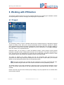
6 Working with IPEmotion ................................................................ 53
6.1
Project ..................................................................................................................................... 53
6.1.1 Configuring project settings................................................................................................. 54
6.2
Signals .................................................................................................................................... 55
IPEmotion
IPETRONIK GmbH & Co. KG
3/ 139
Content
6.2.1 Systems............................................................................................................................... 56
TEDS sensors ................................................................................................................................ 57
6.2.2 Channels ............................................................................................................................. 57
6.2.3 Configuration dialogs........................................................................................................... 58
6.2.4 Using the scaling calculator ................................................................................................ 59
2-point scaling ................................................................................................................................ 60
Free 2-point scaling........................................................................................................................ 60
Factor/Offset scaling ...................................................................................................................... 60
Multipoint scaling............................................................................................................................ 60
STG ................................................................................................................................................ 60
TEDS Sensor ................................................................................................................................. 60
6.2.5 Using the sensor data base ................................................................................................ 60
The data base format ..................................................................................................................... 62
6.2.6 The Import function ............................................................................................................. 64
CANdb, A2L, UDS.......................................................................................................................... 65
DAQ lists ........................................................................................................................................ 65
Diagnosis........................................................................................................................................ 66
6.2.7 Configuration with signal database ..................................................................................... 67
Structure of a signal database ....................................................................................................... 68
6.3
Acquisition............................................................................................................................... 70
6.3.1 Saving ................................................................................................................................. 71
Storage group................................................................................................................................. 71
6.3.2 Formula editor ..................................................................................................................... 72
Operators ....................................................................................................................................... 74
6.3.3 Limit value monitoring ......................................................................................................... 86
Limit value as constant................................................................................................................... 87
Limit value as formula .................................................................................................................... 87
Defining limit values ....................................................................................................................... 88
Displaying limit violations ............................................................................................................... 89
6.4
View ........................................................................................................................................ 90
6.4.1 Using the visual elements ................................................................................................... 90
Alphanumerical display .................................................................................................................. 94
LED ................................................................................................................................................ 95
Action ............................................................................................................................................. 95
6.4.2 Keyboard handling .............................................................................................................. 96
6.5
Data manager ......................................................................................................................... 98
6.5.1 Data formats........................................................................................................................ 99
KML ................................................................................................................................................ 99
TESTdrive video data................................................................................................................... 100
6.6
Analysis................................................................................................................................. 101
6.6.1 x-y/y-t chart........................................................................................................................ 101
6.6.2 Keyboard handling ............................................................................................................ 102
6.7
Scripting ................................................................................................................................ 104
6.7.1 Internal automation interface............................................................................................. 105
IPEmotion
IPETRONIK GmbH & Co. KG
4/ 139
Content
Using scripts................................................................................................................................. 105
7 Practical application examples ................................................... 107
7.1
7.2
7.2.1
7.2.2
7.2.3
7.2.4
7.2.5
7.2.6
7.3
7.4
7.4.1
7.4.2
7.4.3
7.4.4
7.4.5
7.5
Launching IPEmotion............................................................................................................ 107
Running a temperature acquisition ....................................................................................... 108
Project settings.................................................................................................................. 108
Configuring modules and channels................................................................................... 109
Defining storage group(s) and formula(s) ......................................................................... 110
Visually displaying acquisition values ............................................................................... 113
Managing the data............................................................................................................. 114
Displaying and analyzing data .......................................................................................... 115
Defining a pressure channel by using the scaling calculator................................................ 116
Defining a RPM acquisition................................................................................................... 118
Configuring the module and channel ................................................................................ 118
Selecting storage group and channel................................................................................ 120
Visually displaying acquisition values ............................................................................... 121
Managing the data............................................................................................................. 122
Displaying and analyzing data .......................................................................................... 122
Defining a triggered acquisition ............................................................................................ 124
8 Software add-ons ......................................................................... 126
8.1
Climate package ................................................................................................................... 126
8.1.1 Climate calculations .......................................................................................................... 126
Run climate calculations .............................................................................................................. 127
8.1.2 Log p-h diagram online (View) .......................................................................................... 128
Use the log p-h diagram............................................................................................................... 128
Add channels................................................................................................................................ 129
8.1.3 Log p-h diagram offline (Analysis)..................................................................................... 130
Add channels................................................................................................................................ 130
Context menu ............................................................................................................................... 130
Keyboard control .......................................................................................................................... 131
8.2
Control................................................................................................................................... 131
8.2.1 PID controller..................................................................................................................... 131
Use PID controllers ...................................................................................................................... 131
8.2.2 Function generators .......................................................................................................... 133
Use function generators ............................................................................................................... 134
9 External IPEmotion automation interface .................................. 136
9.1
9.2
10
10.1
IPEmotion
Advices for the IPEmotion editions ....................................................................................... 136
Creating runtime versions ..................................................................................................... 137
IPEmotion PlugIn..................................................................... 138
PlugIn-Designer .................................................................................................................... 139
IPETRONIK GmbH & Co. KG
5/ 139
Important information
1 Important information
Please follow these instructions before and during the use and application of any IPETRONIK
product!
1.1 Liability, Warranty, Copyright, License agreement
1.1.1 Limitation of liability
Any liability of IPETRONIK, its representatives, agents and the like, especially with regard to personal
injury or damage to property of any kind, shall be excluded (within the legally admissible framework),
as far as, the instructions and warnings, as mentioned below, have not been followed.
1.1.2 Warranty
Products, accessories and services have a 12 months warranty.
All product data, specifications, drawings, etc., correspond to the current condition of the indicated
creation date. For the purpose of optimizing technical processes and production, some details of our
modules and accessory components may be modified at any time without prior notification.
Although the present document has been prepared with the utmost attention to detail, it may not be
exempt of misprints, typing or transcription errors. These errors are not covered by any warranty.
1.1.3 Copyright and Duplication
We reserve all rights, in particular those of property, copyright and trademarks. The rights related to
any third party trademarks mentioned in the present document remain unaffected.
This document may not be duplicated, partially or entirely without the prior approval from IPETRONIK
GmbH & Co. KG. All graphics and explanations are copyright protected. Any use beyond the scope of
the document is prohibited.
1.1.4 Software license agreement
This software is property of IPETRONIK GmbH & Co. KG, and is protected by copyright laws. Its total
or partial reproduction is strictly forbidden.
1.1.5 General license agreement
IMPORTANT - READ CAREFULLY! THIS IS A LEGAL AGREEMENT BETWEEN YOU, LICENSEE,
AND IPETRONIK GMBH & CO. KG/IPETRONIK INC. ("IPETRONIK"). BY CHECKING “I ACCEPT
ALL OF THE TERMS CONTAINED IN THE ABOVE AGREEMENT” DURING INSTALLATION,
COPYING OR USING THIS PRODUCT IN ANY WAY YOU ACKNOWLEDGE THAT YOU HAVE
READ THIS LICENSE AND THAT YOU UNDERSTAND AND EXPRESSLY AGREE TO BE BOUND
BY THE TERMS AND CONDITIONS SET FORTH BELOW.
IPEmotion
IPETRONIK GmbH & Co. KG
6/ 139
Important information
A valid software license is required to use the IPEmotion software.
1. Definitions
a.
SOFTWARE is defined as computer program in object code or machine-readable
format, together with any and all modifications, enhancements, updates, and
improvements provided by IPETRONIK as well as any subsequent versions,
corrections, bug fixes, enhancements, updates or other modifications, regardless of the
source. The term “Licensed Software” shall not include the source code version of the
Licensed Software.
b.
EQUIPMENT is defined as automotive measuring equipment produced by IPETRONIK
as well as other parties.
c.
LICENSEE is defined as the recipient of this SOFTWARE and any of its employees,
agents or representatives.
d.
MODIFY or MODIFICATION is defined as change to the SOFTWARE by LICENSEE in
order to customize the SOFTWARE for use solely by LICENSEE.
2. License Terms
IPEmotion
a.
As long as LICENSEE complies with all terms in this Software License Agreement
IPETRONIK grants LICENSEE a non-exclusive, non-transferable license to load and
use the SOFTWARE upon the terms and conditions set forth below.
b.
LICENSEE has the right to load the SOFTWARE for use on any internal computer or
piece of EQUIPMENT, as long as it is only on one computer or piece of EQUIPMENT at
any given time.
c.
LICENSEE will notify all of its employees, agents or representatives permitted access to
the SOFTWARE of the duties and obligations under this Software License Agreement.
d.
LICENSEE has the right to MODIFY the SOFTWARE for use on any internal computer
or of EQUIPMENT, as long as it is only on one computer or piece of EQUIPMENT at
any given time.
e.
Any MODIFICATION(S) to the SOFTWARE are subject to the terms and conditions of
this Agreement.
f.
LICENSEE may not:
i. Loan, rent, lease, give, sublicense, distribute, transmit or otherwise transfer the
SOFTWARE, or otherwise exercise any of IPETRONIK's legal rights in and to the
SOFTWARE, or any derivative works of the SOFTWARE, in whole or in part,
except with the prior written agreement of IPETRONIK.
ii.
Copy, translate, reverse engineer, decompile, disassemble the SOFTWARE, in
whole or in part.
iii.
Except as provided is Section 2(d), create derivative works based on the
SOFTWARE, in whole or in part.
IPETRONIK GmbH & Co. KG
7/ 139
Important information
iv. Remove, modify or cause not to be displayed any copyright or trademark notices,
license agreements, or startup messages contained in the programs or
documentation.
v.
Transmit or otherwise export outside of the Unites States any of the SOFTWARE
or technology in violation of United States or other applicable laws or regulations.
3. Ownership of Intellectual Property
LICENSEE agrees and acknowledges that the SOFTWARE is being provided to it only for
use in EQUIPMENT in the ordinary course of business and that LICENSEE agrees and
acknowledges that IPETRONIK is the owner of all title and proprietary rights in the
SOFTWARE, including, without limitation, any and all patents, copyrights, trademarks or any
other intellectual property rights associated with it under the laws of the United States or any
jurisdiction throughout the world. No right, title or interest in the SOFTWARE or any
IPETRONIK patent, copyright, trademark, or any other intellectual property right is
transferred to LICENSEE or any other party through this Software License Agreement.
4. Disclaimer of Warranties; Liability Limitations
a.
THE SOFTWARE IS PROVIDED TO YOU "AS IS". THERE ARE NO WARRANTIES
OF ANY KIND, WHETHER EXPRESS OR IMPLIED, INCLUDING BUT NOT LIMITED
TO THE WARRANTIES OF MERCHANTABILITY, FITNESS FOR A PARTICULAR
PURPOSE AND COMPATIBILITY, AND TITLE.
b.
LICENSEE ASSUMES ALL RISK AS TO THE SELECTION, USE, PERFORMANCE
AND QUALITY OF THE SOFTWARE. IN NO EVENT WILL IPETRONIK OR ANY
OTHER PARTY WHO HAS BEEN INVOLVED IN THE CREATION, PRODUCTION OR
DELIVERY OF THE SOFTWARE BE LIABLE FOR SPECIAL, DIRECT, INDIRECT,
INCIDENTAL OR CONSEQUENTIAL DAMAGES, INCLUDING LOSS OF PROFITS OR
INABILITY TO USE THE LICENSED MATERIAL. IN NO EVENT SHALL IPETRONIK'S
LIABILITY FOR ANY DAMAGES OR LOSS TO LICENSEE OR TO ANY THIRD PARTY
EXCEED ANY LICENSE FEE ACTUALLY PAID BY THE LICENSEE TO IPETRONIK
FOR THE SOFTWARE.
c.
Since some states or jurisdictions do not permit the exclusion of implied warranties or
limitation of liability for consequential damages, in such states or jurisdictions, the
liability is limited to the fullest extent permitted by law.
5. Intellectual Property Infringement Indemnification
a.
IPETRONIK shall defend, indemnify, and hold LICENSEE harmless from and against
any claims and fees (including attorneys’ fees), damage awards arising in connection
with a claim that the licensed SOFTWARE or documentation, when properly used,
infringes upon any presently existing, valid and enforceable United States patent,
trademark, or other intellectual property right, provided that:
i.
such claim of infringement is not based on any Modification or action taken or
suffered by LICENSEE other than the use of the licensed SOFTWARE and
documentation in accordance with the terms and conditions of this agreement;
ii.
IPEmotion
such claim of infringement is not based on any action by LICENSEE in modifying
the SOFTWARE pursuant to the terms of Section 2(d).
IPETRONIK GmbH & Co. KG
8/ 139
Important information
b.
c.
iii.
LICENSEE promptly notifies IPETRONIK of such claim in writing at
[email protected], and gives IPETRONIK exclusive control over the defense
and settlement of such claim;
iv.
LICENSEE provides such cooperation and assistance, at IPETRONIK’S expense,
as IPETRONIK may reasonably request to settle or oppose any such claim; and
v.
such claim of infringement is based only on the licensed SOFTWARE and
documentation as provided to LICENSEE.
In the event of any infringement claim for which IPETRONIK is liable pursuant to section
5 (a), IPETRONIK may, at its sole option and expense:
i.
procure for LICENSEE the right to continue using the licensed SOFTWARE or
documentation;
ii.
modify or amend the licensed SOFTWARE or documentation so that it becomes
non-infringing;
iii.
replace the licensed SOFTWARE or documentation with a non-infringing
substitute; or
iv.
recover the infringing licensed software and documentation from LICENSEE and
repay to LICENSEE all license fees paid to IPETRONIK in connection therewith,
less a reasonable amount based on LICENSEE’s use prior to such recovery and
refund.
This Article 5 sets forth IPETRONIK’s sole obligations and liability for intellectual
property infringement. These indemnity provisions only apply to the SOFTWARE as
originally licensed to LICENSEE and do not cover any MODIFICATIONS made by
LICENSEE or any other third party.
6. Limitation of Liability
a.
EXCEPT WITH RESPECT TO ITS INTELLECTUAL PROPERTY INDEMNIFICATION
OBLIGATIONS, AS SET FORTH IN ARTICLE 5, IN NO EVENT SHALL IPETRONIK BE
LIABLE FOR SPECIAL, INDIRECT OR CONSEQUENTIAL DAMAGES (INCLUDING,
WITHOUT LIMITATION, LOST PROFITS, LOST DATA, OR LOST SAVINGS), EVEN IF
IPETRONIK WAS ADVISED OF THE POSSIBILITY OF SUCH DAMAGES.
FURTHERMORE, IPETRONIK’S LIABILITY (WHETHER IN CONTRACT, TORT, OR
OTHERWISE) ARISING OUT OF, OR CONNECTED WITH, THIS AGREEMENT OR
THE LICENSED SOFTWARE OR DOCUMENTATION SHALL IN NO CASE EXCEED
THE PAYMENTS RECEIVED BY IPETRONIK FROM LICENSEE FOR THE LICENSED
SOFTWARE AND DOCUMENTATION.
b.
EXCEPT IN CONNECTION WITH ITS OBLIGATIONS UNDER ARTICLE 5:
i.
IN NO EVENT SHALL LICENSEE BE LIABLE FOR SPECIAL, INDIRECT OR
CONSEQUENTIAL DAMAGES (INCLUDING, WITHOUT LIMITATION, LOST
PROFITS, LOST DATA, OR LOST SAVINGS), EVEN IF LICENSEE WAS
ADVISED OF THE POSSIBILITY OF SUCH DAMAGES; AND
ii.
IPEmotion
LICENSEE’S LIABILITY (WHETHER IN CONTRACT, TORT, OR OTHERWISE)
ARISING OUT OF, OR CONNECTED WITH, THIS AGREEMENT OR THE
LICENSED SOFTWARE OR DOCUMENTATION SHALL IN NO CASE EXCEED
THE PAYMENTS OWED TO LICENSOR FOR THE LICENSED SOFTWARE AND
DOCUMENTATION.
IPETRONIK GmbH & Co. KG
9/ 139
Important information
7. Indemnification Obligations of LICENSEE
a.
LICENSEE shall defend, indemnify, and hold IPETRONIK harmless from any claims,
losses, expenses, fees (including attorneys’ fees), costs or damages arising in
connection with a MODIFICATION or LICENSEE’S unauthorized use of the Licensed
Software or Documentation.
8. Merger Clause
a.
LICENSEE agrees that this Software License Agreement is the complete and exclusive
agreement between LICENSEE and IPETRONIK governing the SOFTWARE. This
Software License Agreement supersedes and merges all prior agreements with
IPETRONIK concerning the SOFTWARE and can only be modified by a subsequent
written agreement signed by IPETRONIK. To the extent that there is any conflict
between this Software License Agreement and any IPETRONIK purchase order or other
written agreement for the purchase of IPETRONIK parts or products, the terms of the
purchase order or written agreement control.
9. General
IPEmotion
a.
If any provision or portion of a provision of this Software License Agreement is
determined to be invalid or unenforceable, it shall be deemed omitted and the remaining
provisions of this Software License Agreement shall remain in full force and effect to the
fullest extent permitted by law.
b.
LICENSEE may not assign or transfer all or part of this Software License Agreement to
any third party without the express written approval of IPETRONIK.
c.
This Software License Agreement will be governed by the laws of the State of Michigan
without regard to its conflict of laws provisions.
d.
All disputes arising out of, or in connection with, the present contract shall be finally
settled under the Rules of Arbitration of the International Chamber of Commerce by one
or more arbitrators appointed in accordance with the said Rules.
IPETRONIK GmbH & Co. KG
10/ 139
General information
2 General information
2.1 About this manual
The manual IPEmotion describes the structure of the software and how to use the features for
configuring devices, acquire data, manage, manipulate and analyze the acquired data.
Please read the manual IPEmotion carefully to get to know the software and learn more about the
functions and special features of IPEmotion before using the product. This manual also contains
information for installing and removing the software.
The main navigation point Info allows you an easy and quick access to the IPEmotion software .
While working with IPEmotion, you can reference to this manual at any time via the
buttons.
and
2.2 Version
2.2.1 Manual IPEmotion
This manual has the version number 02.00.
2.2.2 IPEmotion
The descriptions in this documentation refer to the current release of IPEmotion with the version
number 02.00.
2.3 Legend of the used icons
IPEmotion
Tip
This icon indicates a useful tip that facilitates the application of the
software.
Information
This icon indicates additional information for a better understanding.
Attention!
This icon indicates important information to avoid potential error
messages.
IPETRONIK GmbH & Co. KG
11/ 139
General information
2.4 Support
Headquarter:
IPETRONIK GmbH & Co. KG
Im Rollfeld 28
76532 Baden-Baden, Germany
Tel. +49 72 21 99 22 0
Fax +49 72 21 99 22 100
[email protected]
www.ipetronik.com
Limited commercial partnership with its head office in Baden-Baden, registry court HRA No. 201313
IPETRONIK Verwaltungs-GmbH Baden-Baden is an individually liable society, registry court
Mannheim HRB No. 202089
Management: Erich Rudolf, Andreas Wocke
Technical support and product information
You are a customer with an IPEmotion service contract:
Please find the free hotline number in your valid service contract.
You are a customer without an IPEmotion service contract:
Send us your inquiry to [email protected].
2.5 Product licensing
IPEmotion is a copy-protected software. It uses a copy protection in the form of a license
key.
To be able to use IPEmotion, you need a valid license key. If no valid license key is available, please
contact IPETRONIK GmbH & Co. KG to purchase a license.
2.6 Related documentations
2.6.1 IPEmotion COM
The documentation IPEmotionCOM.chm provides you with a description and useful information
related to the COM interface in IPEmotion. This documentation is stored in the following standard
directory: C:\Programs\IPETRONIK\IPEmotion Vxx.xx.xx\Help.
2.6.2 Hardware
The documentation for each installed plugin is stored in the respective program folder. This
documentation is created by each producer on one’s own responsibility.
IPEmotion
IPETRONIK GmbH & Co. KG
12/ 139
General information
2.7 Documentation feedback
At IPETRONIK, the technical publications team strives to produce documentations of the highest
quality and values your feedback as a reader and user. If you have any comments or suggestions
regarding our product manuals, contact us under [email protected].
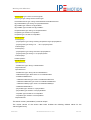
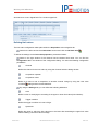
When commenting on our products, please include the following information:
Version number (Select About from the menu to display the version number.)
Name of the guide
Page number or section title
Brief description of the content (e.g. inaccurate instructions, grammatical errors, or information
that require clarification)
Any suggestions for a general documentation improvement
IPEmotion
IPETRONIK GmbH & Co. KG
13/ 139
Introduction
3 Introduction
To get started, please read this document carefully to get to know the functions and special features of
IPEmotion.
In addition to acquiring data from hardware modules using IPEmotion, you can initialize, program, and
configure various hardware measuring modules.
IPEmotion is software for configuring, displaying, measuring and storing acquisition data.
After acquiring and storing data using IPEmotion, you can manipulate, analyze, and generate reports
for documentation purposes on the basis of the recorded data.
For more information about the functionality and the known restrictions please consult the Release
Notes of your IPEmotion software.
We are looking forward to your feedback at: [email protected].
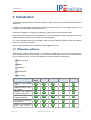
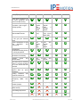
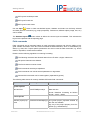
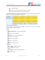
3.1 IPEmotion editions
IPEmotion is available in different editions. The following chapter shows an overview with information
about all editions and their functionality. You can find out which edition meets your requirements and
fits your needs the most. You can select between the following editions of IPEmotion:
Demo 30 days
Basic
Standard
Professional
Developer
Function:
Demo 30
days
Basic
Standard
Professional
Developer
Multilingual user interface
+ Help
Predefined skins for day /
night visibility
Integrated user guidance
for system configuration
Project settings for data
managing using XML
Automatic device detection
+ configuration
Integration of manufacturer
specific data sources /
IPEmotion
IPETRONIK GmbH & Co. KG
14/ 139
Introduction
sinks (3rd party hardware)
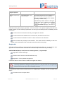
Exact time synchrony for
all used interfaces and
devices at data storing
Channel based signal
acquisition (with trigger +
storage groups)
max.
10 max.
256
signals,
signals,
max.
1 max.
2
storage
storage
group
groups
Direct storing of data in
different data formats
(IAD, DAT, (IAD, DAT,
CSV)
CSV, Excel
2003 XML)
Online visualization of data
in the grid (All Channel
View)
Online visualization of data
with
diagrams
and
instruments
max.
10 max.
256
signals,
signals,
max.
1 max.
5
page
pages
Customizing
visualization/scaling during
a running acquisition
Wide
channel
based
calculation functionality
Analysis
(Load
validate data)
and
max.
10 max.
256
signals
signals
View and correct channels
during a running acquisition in the same SW user
interface
Integrated
creation
of
support files for quick
assistance
Scaling calculator
graphical assistance
with
Import description files for
configuring (DBC, A2L,
etc.)
Load data with
formats (Import)
Import signal
(MPC format)
other
(only DAT)
database
Automating sequences
Creation of runtime
IPEmotion
IPETRONIK GmbH & Co. KG
15/ 139
Introduction
versions
Service contract obligation
IPEmotion
IPETRONIK GmbH & Co. KG
16/ 139
Setting up and removing
4 Setting up and removing
4.1 System requirements
The minimum hardware and software requirements for the application of IPEmotion are outlined
below:
4.1.1 Hardware
PC with 1 GHz Pentium processor,
1 GB RAM,
Hard disk with a minimum of 100 MB free disk space,
Graphics card with VGA screen and a resolution of minimum 1.024 x 768,
USB port for the installation from the USB flash drive,
CD-ROM drive for the installation from the product CD.
4.1.2 Platforms
The software IPEmotion can be run under the following operating system:
Windows XP (Service Pack 2 or higher, 32 Bit only),
Windows Vista (32 Bit and 64 Bit),
Windows 7 (32 Bit and 64 Bit).
4.1.3 Software
The following software will be installed:
Microsoft .NET 3.5 Framework incl. Language packages German and French,
Microsoft MSXML 4.0,
Microsoft Visual C++ 2005 Redistributable.
IPEmotion
IPETRONIK GmbH & Co. KG
17/ 139
Setting up and removing
4.2 Installing IPEmotion
The following chapter guides you through the installation process of IPEmotion.
IPEmotion needs administrator rights during the installation. Working with IPEmotion
requires that you need at least limited user’s or default user’s rights (Vista).
For running IPEmotion without administrator rights and with Windows 7 contact your system administrator. Please find basic information about configuring the User Account Control
in
the
following
links:
http://en.wikipedia.org/wiki/User_Account_Control,
http://technet.microsoft.com/en-us/library/dd835546(WS.10).aspx.
The installation of IPEmotion is based on an installation wizard that guides you through the setup
process step by step. You can start the installation wizard from the USB flash drive, the product CD or,
if you have downloaded the setup program, from the setup file itself.
To install the IPEmotion software:
1. Start the installation wizard from the USB flash drive, the product CD or from the setup file.
USB flash drive: Connect the USB flash drive to the USB port of your computer and follow the
instructions of the installation wizard.
Product CD: Launch the product CD and click Install Software on the Welcome screen. On
the Install Software screen, click Install IPEmotion to start the installation wizard.
Setup file: Browse the location of the setup file and double-click IPEmotion.exe to start the
installation wizard.
Depending on the PC operating system, a security warning appears. Click Run to start the
installation wizard.
2. Setup language/Setup-Sprache/Langue d’installation: Select the language for the installation
process. You can choose between the languages German (Germany), English (United States) and
French (France).
Click OK to start the IPEmotion installation wizard.
3. Welcome screen: This is the first screen in the IPEmotion installation wizard.
Click Next to continue.
IPEmotion
IPETRONIK GmbH & Co. KG
18/ 139
Setting up and removing
4. License agreement: Read the license agreement carefully and accept the included conditions.
Click Next to continue.
5. Customer information:
Please enter your customer information. Click Next to continue.
6. Hardware system: Select the desired hardware system or deactivate the hardware not to be used.
Click Next to continue.
7. Setup type: Choose the desired type of installation.
With the standard installation, you can select between the standard installation for the logged in user
and a standard installation for all users.
If you select the Standard installation skip the following point Destination folder. Click Next to
continue with point 8.
If you select Custom you can choose user-specific settings according to the destination folders. Click
Next to display the following dialog.
Destination folder:
Due to the security model of Microsoft Corporation related to .NET applications, the
installation of IPEmotion on a local drive is recommended.
According to the Microsoft conformance guidelines for Windows applications the
IPEmotion files are installed to the default locations that are specific to the operating
system and language.
Accept the default installation location for IPEmotion, the application data, and the user data. To select
another location click Change.
After you have specified the location for the IPEmotion installation, click OK to return to the
Destination folder screen.
Click Next to continue.
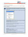
8. Ready to install the program: This screen indicates that IPEmotion is ready to install.
Click Install to start the installation.
9. Installing IPEmotion: A progress bar is shown during the installation process.
10. Installing hardware system(s): Follow the instructions of the installation wizard to install the
selected hardware systems.
11. InstallShiel Wizard Completed: After the successful installation, the following screen is shown.
IPEmotion
IPETRONIK GmbH & Co. KG
19/ 139
Setting up and removing
Click Finish to exit the installation wizard.
IPEmotion is now shown as an icon on your desktop as well as in the menu Start → Programs →
IPETRONIK → IPEmotion.
Due to the fact that the IPEmotion installation file is a exe standard setup file, user-specific
parameter configurations can be made with a silent installation, e.g. options for installation,
indication, repair.
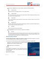
With the entry of the command msiexec the following screen appears where the possible
administrative installing options are listed.
For the silent installation of IPEmotion, call Setup IPEmotion.exe with /S /v/qn parameters.
A Windows-Silent-Setup cannot run other setups in silent mode, the plugins must therefore
be installed as silent, too:
Setup IPEmotion PlugIn IPETRONIK LOG.exe /S /v/qn
Setup IPEmotion PlugIn IPETRONIK CAN.exe /S /v/qn
LOGGER-Plugin setup copies LOG2PC-Core into Temp directory and installs LOG2PCCore in Silent mode, which must also be installed separately:
Setup LOG2PC Core.exe /S /v/qn
CAN-Plugin setup copies CAN-Server into Temp directory and installs CAN-Server in Silent mode, which must also be installed separately:
msiexec /i ".../IPETRONIK CAN-Server.msi"/qn
If directories are used, which differ from the standard directories, the respective property
has to be set:
INSTALLDIR="Directory for programs"
INSTALLDIR_USERDATA="Directory for user data"
INSTALLDIR_APPDATA="Directory for application data"
If directories contain spaces \" has to be used.
Example:
Setup IPEmotion.exe /S /v"/qn INSTALLDIR=C:\Programs\Example\IPEmotion INSTALLDIR_USERDATA=D:\User data\IPEmotion"
Please note that the program data and application data cannot be used simultaneously by
IPEmotion
IPETRONIK GmbH & Co. KG
20/ 139
Setting up and removing
different IPEmotion versions.
Deinstallation runs with Setup.exe via the /X key by using the setup of the version to be
uninstalled.
Example:
Setup IPEmotion.exe /S /X /v"/qn"
4.3 IPEmotion License
The following chapter offers you an overview about the licensing process for the IPEmotion software.
By using this licensing, optional program features, which depend on the purchased IPEmotion edition,
are available after a successful installation of IPEmotion. Please find further information according the
editions in chapter 3.1 IPEmotion editions.
IPEmotion contains basically at delivery all program features. The corresponding functions and
contents are unlocked by using the licensing.
The license model of IPEmotion differs between the following three basic models:
Free demo version for 30 days with full functionality
Free basic version with limited functionality
Several versions against charge with graded functionlity
The free demo version for 30 days allows you to get to know IPEmotion with unlimited functionality.
The free but limited basic version shows you the functionality of the versions against charge.
Before being able to activate the software, you have to register on the IPEmotion
homepage www.ipemotion.com.
The following activation runs online or by e-mail. A use of the software is not possible
without a prior valid activation of IPEmotion!
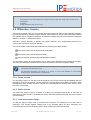
4.3.1 Demo version
The free demo version for 30 days must be activated. You get the license key immediately after the
registration. Enter this license key into the IPEmotion Licensing dialog at first start of IPEmotion. After
the expiration of the 30 days, the demo version turns automatically into the free basic version, which
has not to be unlocked.
4.3.2 Basic version
The free basic version must be licensed. At entering the purchased license key at first start of
IPEmotion, the basic version is activated and can be used with limited functionality. An unlock process
is not necessary.
4.3.3 Versions against charge
All versions against charge must be activated and unlocked. The activation runs at first start of
IPEmotion. The versions against charge have to be unlocked within 30 days. Otherwise, the
purchased version turns automatically into the basic version with limited functionality.
IPEmotion
IPETRONIK GmbH & Co. KG
21/ 139
Setting up and removing
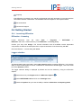
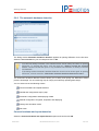
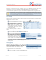
4.3.4 Licensing IPEmotion
Follow the instructions for installing IPEmotion and directly license it for this PC.
1. Launch
IPEmotion.
IPEmotion
from
the
menu
Start
→
Programs
→
IPETRONIK
→
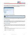
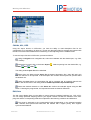
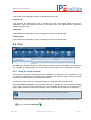
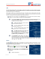
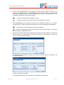
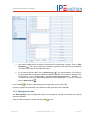
2. The appearing dialog shows an overview of possible steps. Select one of the listed options.
Assign an available license key. – Follow the instructions for registering and unlocking
IPEmotion (see steps 3 – 4).
Buy IPEmotion online. – Get the desired IPEmotion version online and follow the licensing
process (see steps 1 – 4).
Enroll for unlimited testing of all functions for 30 days.
Testing of all functions without restrictions; this screen appears at every start of IPEmotion.
Do not enroll and use permanently as limited basic version.
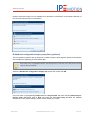
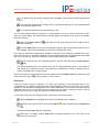
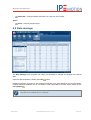
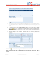
3. Enter in the IPEmotion – Licensing dialog a valid activation key. Confirm your selection with
Assign. The license information and all available version dependent components are listed in the
description field.
IPEmotion can now be used for 30 days. A version against charge has to be unlocked
within 30 days. Otherwise, the purchased version turns automatically into the basic
version with limited functionality.
IPEmotion
IPETRONIK GmbH & Co. KG
22/ 139
Setting up and removing
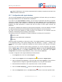
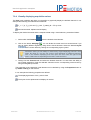
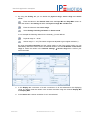
4. To finally unlock IPEmotion, you need an unlock key. Enter the shown registration key in the
IPEmotion homepage or send it to [email protected]. After that, you receive the unlock key.
Enter this Unlock key in the corresponding field and confirm with Assign. The license information and
all available version dependent components are listed in the description field.
5. Exit the IPEmotion – Licensing dialog with Close.
The IPEmotion – Licensing dialog can also be opened by using the About → Licensing
function.
From IPEmotion V01.05 on, you have the ability to license IPEmotion with a dongle. The dongle is a
special USB flash drive, which automatically starts the IPEmotion installation at connecting to PC.
Single license dongle
The dongle includes a single license for IPEmotion. If you have already installed IPEmotion, a manual
input of the license is required (see steps 3-4). The license is stored in the directory generated by the
dongle. The dongle must always be connected to PC at working with IPEmotion. If the dongle is removed during operation, IPEmotion is closed, too (with delay).
Multiple license dongle
The multiple license dongle includes at least 1 license and offers a decisive advantage: the dongle
must not remain connected with the PC at working with IPEmotion! Furthermore, you can return a
license to the dongle that is no longer required. The IPEmotion software is then executed as Basic
edition.
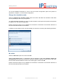
Start IPEmotion.
Connect the dongle with the PC and wait until the blue LED at the dongle is no longer flashing
but is red. This process can take some seconds.
Open the dialog IPEmotion – Licensing.
IPEmotion
IPETRONIK GmbH & Co. KG
23/ 139
Setting up and removing
Enter the corresponding license code and click Get.
The assigned license code is now displayed as hidden and the included license information is
listed. Click Give to return the license to the dongle. IPEmotion is now available as Basic edition.
You can now disconnect the dongle from the PC and work with IPEmotion.
IPEmotion
IPETRONIK GmbH & Co. KG
24/ 139
Setting up and removing
4.4 Uninstalling IPEmotion
The following chapter shows the deinstallation process of IPEmotion.
For removing IPEmotion you have two possibilities:
The option Remove of the IPEmotion installation program.
The option Add or Remove Programs for IPEmotion in the Control Panel.
With both methods you can remove IPEmotion files, folders and registry entries from your computer,
which has been created during the installation.
Please note that the installed plugins are not uninstalled automatically but have to be
deleted separately!
Removing IPEmotion with the installation program
To do so, proceed as follows:
1. Click in the menu Start on your computer on Settings and then Control Panel.
2. Double-click in the Control Panel on Add or Remove Programs.
3. Select from the program list the entry IPEmotion and click Change to start the installation wizard.
Click Next to advance to the Program maintenance screen.
4. Program maintenance: This screen allows you to modify, repair or remove IPEmotion. Select
Remove and click Next to continue.
5. Remove the program: This screen indicates that your installation is now ready to remove. Click
Remove to start the removing process.
6. Uninstalling IPEmotion: A progress bar is shown during the uninstalling process.
7. InstallShiel Wizard Completed: This screen is shown after the successful deinstallation. Click
Finish to exit the installation wizard.
After removal, IPEmotion is no longer indicated in the program list.
Removing IPEmotion with the deinstallation function of the Control Panel
To do so, proceed as follows:
1. Click in the menu Start on your computer on Settings and then Control Panel.
2. Double-click in the Control Panel on Add or Remove Programs.
IPEmotion
IPETRONIK GmbH & Co. KG
25/ 139
Setting up and removing
3. Select from the program list the entry IPEmotion and click Remove to start the installation wizard.
4. Click Yes to start the deinstallation.
5. A progress bar is shown during the uninstalling process.
6. After the successful removal of IPEmotion, the program has been removed from your computer and
is no longer indicated in the program list.
IPEmotion
IPETRONIK GmbH & Co. KG
26/ 139
Getting Started
5 Getting Started
The following chapter offers an overview of the available commands and their functions. In addition,
the first basic steps for using IPEmotion are explained.
5.1 The title bar
The title bar contains the quick access bar (see chapter 5.5), the software name, as well as, a tool bar
with the following functions:
Help – Open the documentation IPEmotion.pdf where you can find useful information for a safe
and clean application of the software.
Minimize – Minimize the application window of IPEmotion and place it in the task bar of your
desktop.
Maximize – Make the application window visible on your desktop and refit the prior size.
Close – Close the IPEmotion application.
5.2 The application button
Click on the
button to open the application menu.
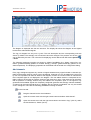
5.3 The application menu
The application menu contains basic functions as: New, Open, Save, Save As, Runtime version,
Print and Close, as well as, further properties such as View, Options, Support file and About.
The right partial view of the application menu contains a list of the recently used projects.
The Print function is implemented with limited functionality and not yet localized.
The View function contains the menu points Message window and the Reset command. Show or
hide the message window and reset the displaying configuration to the default parameters.
IPEmotion
IPETRONIK GmbH & Co. KG
27/ 139
Getting Started
5.3.1 Layout designer
IPEmotion offers the ability to create individual reports with an integrated editor. A predefined layout
guarantees a consistent style of all report pages. Every object (text, line, image, etc.) can be added to
the editor with Drag&Drop and modified (change size, color, etc.).
Open the Designer with the Layout designer
layout is loaded at starting the layout function.
menu point. The last used
The current version offers the following standard elements:
Image
Text
Line
Rich text
Arrow
The layout creation in IPEmotion allows to choose between 5 standard formats:
Empty layout
IPELayout Landscape A4
IPEmotion
IPETRONIK GmbH & Co. KG
28/ 139
Getting Started
IPELayouot Landscape Letter
IPELayout Portrait A4
IPELayout Portrait Letter
button to load user-defined layouts. Headers and footers can be freely selected
Use the Open
and allow place for comments (e.g. project properties). Furthermore, different object (image, text, etc.)
can be added.
button allows to define the current layout as standard. This activates the
The Standard layout
layout for the preview and the reporting page.
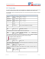
Field commands
Field commands are an important feature of word processing programs and offer the ability to integrate variable information in the text. Field commands include information, which is automatically updated, e.g. date, time. Project-specific parameters can also be used as field commands, e.g. device
used for acquisition, measurement software.
Please note the following regulations concerning formatting:
The following characters are allowed: letters from A-Z and a-z, digits, underscore.
No special characters are allowed.
The first character must be a letter.
Field commands are always capitalized.
Field commands can include several parameters or arguments.
Several field commands can be used together (separated by space).
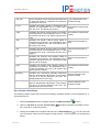
The following table shows all currently available IPEmotion field commands:
Option
Formatting
Functionality
%DATETIME(format)%
Date and time
System-specific
Date and time
format: Date/time formatting as follows:
format = m/dd/ -> 9/26/)
Online-specific
Different project prop- %PROJECTPARAM(key)% The global project properties defined by
erties
the user are available.
key: key of the project property from ProjectPar (e.g. SerialNumber)
IPEmotion
IPETRONIK GmbH & Co. KG
29/ 139
Getting Started
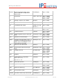
Analysis-specific
Different project prop- %DATAPROPERTY(key;
erties
noDataGroup)%
The project properties of the measurement
files defined by the user are available.
key: key of project property from parameter field (or header of file)
noDataGroup: define number of data group from data pool for defining the project
property.
If
none
is
defined
(%DATAPROPERTY(key)%), the first is
chosen.
IPEmotion offers global project properties. You have access to any project property with field commands. Please note the following specification concerning the formatting and the availability of field
commands:
If a field command is entered incorrectly, the original text remains.
If a field command is invalid but has a correct format, the text turns into “Error”.
If a field command is valid but contains no data, the text turns into “No data”.
Field commands are partially context-sensitive. That means that the availability of field commands can be restricted and the commands cannot be used for every page.
Script calls
IPEmotion offers the ability to connect internal scripts with field commands, e.g. to calculate the average value of a channel. A field command with connected script has the following formatting:
%SCRIPTINVOKE(Script name;Function name;Argument1;...;ArgumentN)%
Script name: name of the script
Function name: function to be called with the script
Argument1 – N: any number of arguments
If functions without a return value are called, the original text remains.
It is necessary to ensure that the script called with a field command does not run timeconsuming operations. Calling the printing function or the print view can be significantly
delayed because the script is first completely executed.
The following overview shows potential reasons for displaying the message “An error occurred in the
script.”:
A function not in the script is called.
IPEmotion
IPETRONIK GmbH & Co. KG
30/ 139
Getting Started
Wrong transfer parameters are entered (script name, function name, argument).
The formatting of the field command is invalid.
The script does not exist.
Field commands in layout designer
IPEmotion allows to use field commands with the Text
and Rich text
mands edited in the designer are interpreted at printing and in the print preview.
The Field names
elements. The com-
button allows to switch between the name of the field command and its content.
5.3.2 View
The View
function includes the following points,
Message window
Status window
PC status window
Storage status window
Output window
as well as, the commands:
Reset
Reset templates
– Reset the templates of the View and Analysis main navigation tabs.
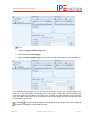
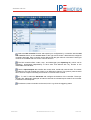
5.3.3 Using the options
With the Options entry, you have the ability to edit user-defined settings. You can define the following
options:
Frequently used
Basic settings
Appearance
Data manager
IPEmotion
IPETRONIK GmbH & Co. KG
31/ 139
Getting Started
Analysis
Directories
Units
Hotkey
PlugIns
The following section offers you a detailed overview over the available setting options.
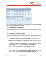
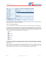
Frequently used
Activate or deactivate Start with the latest configuration and define the settings for the automatic
hardware detection. Activate or deactivate the automatic hardware detection at start of IPEmotion
and select a possible standard command after successful detection:
Guided configuration
Automatic configuration
Manual configuration
Basic settings
Select a preferred configuration type:
Hardware configuration
Signals configuration with selection of the signal database
Activate or deactivate the options: Accurate acquisition chain required and Expert mode.
IPEmotion
IPETRONIK GmbH & Co. KG
32/ 139
Getting Started
Appearance
Define your view settings according the following listed points:
Language selection
Skin selection
Displaying tooltips
Font size of the visual elements
Transparency of configuration dialogs (0 – 30 percent)
Activate or deactivate the use of the Windows standard dialogs for the file and directory selection.
The Open file dialog is skin-enabled, i.e. it is shown in the selected user interface type.
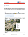
Data manager
Define the Time channel format as Relative or Absolute (This setting is currently not supported for
the export into external formats!) and activate or deactivate the option: Merge time channels with
equal acquisition rate.
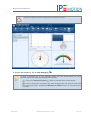
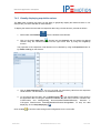
Analysis
Select the points per diagram graph. Define if all signals are considered in the analysis diagrams at
drawing the graph or only the samples. Move the bar accordingly to the preferred speed or quality.
IPEmotion
IPETRONIK GmbH & Co. KG
33/ 139
Getting Started
Directories
IPEmotion additionally offers to the selection of the listed directories the possibility to import the user
settings (language, selected columns, ...), as well as, the plugin options. The user settings are stored
in the IPEmotion application data in the “Settings.xml“ file and the files of the “UserSettings“ sub
folder. Please note with Settings.xml that the directories for the user data directories and the application data directories are stored in the same file. The plugin options are stored in the IMO files in the
plugin folder of the application data.
Units
Get an overview according the common physical values and their respective unit and edit them.
Hotkey
Send specific commands to IPEmotion by using the hotkeys.
IPEmotion
IPETRONIK GmbH & Co. KG
34/ 139
Getting Started
IPEmotion offers you the ability to connect hotkeys with scripts or programs and to run them per key
activation or click. You can load internal scripts from the scripting environment, as well as, external vbs
files. The external scripts are then loaded into the scripting environment.
Open the Area: Scripting entry and double-click Scripting-Script-Run. Assign a hotkey to
the new command. Additionally select the desired script within the Entry column. Confirm your
definitions with OK.
PlugIns
Activate or deactivate the hardware systems to be used.
Plugin-specific options
You can define additional settings for the respective plugin with the specific options.
With the
button, you have the ability to define the components (module type and priority, e.g. for
the type selection of the Dry configuration) of the respective hardware system and to edit additional
options settings.
IPEmotion
IPETRONIK GmbH & Co. KG
35/ 139
Getting Started
The selection of the hardware components for the configuration by using a signal database is based
on the Priority. This preselection with a priority assignation of the system components facilitates the
device selection and improves the system speed.
The High priority defines a preferred use of the corresponding hardware component at configuring
with a signal database. The hardware components, which are defined with the Not used priority,
cannot be selected for an acquisition.
button allows you to select of different installed plugin versions. If a version description is
The
marked with =, this version will always be used – even if the latest version is installed.
The
The
browser.
button opens the manual (pdf) of the respective plugin (if available).
button opens the PlugIn download page at www.ipemotion.com in your standard
5.3.4 Creating a support file
With the Support file entry of the application menu, you have the ability to create a support file and
add and/or edit own comments and error descriptions.
Enter in the appearing Create support file screen an error description. Accept the default location for
the file. To select another location click on the
symbol.
After you have specified the location and a user-defined file name, click Save to return to the Create
support file screen.
IPEmotion
IPETRONIK GmbH & Co. KG
36/ 139
Getting Started
After clicking on OK a zip file is generated that contains the error description, as well as, the following
information:
System information (Windows version, computer name, free memory on the local drives, …)
Current configurations (acquisition, online view, script configurations)
Trace files (.NET, C++)
If you have any problems while working with IPEmotion, send us this support file at
[email protected].
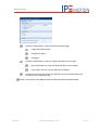
5.4 The quick access bar
The quick access bar is integrated in the title bar and contains functions that are frequently used. Each
of these functions is displayed as an icon. The position of the quick access bar can be customized by
the arrow symbol .
New – Create a new file.
Open – Open an already existing configuration.
Save – Save the current file(s).
Save as – Save the current file(s) with a new name.
Automatic generation – Automatically generate a configuration by reading the connected
devices for measuring and visualizing the signals.
Quick print – Print the current view directly on the standard printer. This function is implemented
with limited functionality.
Cut – Move the selected elements into the clipboard.
Copy – Copy the selected elements into the clipboard.
Paste – Enter the elements from the clipboard.
IPEmotion
IPETRONIK GmbH & Co. KG
37/ 139
Getting Started
Delete – Delete the selected elements.
Clean – Delete all subordinate elements.
Undo – Undo your last action(s).
Redo – Redo previously undone actions step by step.
Properties – Open the configuration dialog.
Options – Define user-defined properties.
Help – Open the IPEmotion.pdf documentation where you can find useful information for a safe
and clean application of the software.
About – Get an overview of the software version and license information of the IPEmotion
software.
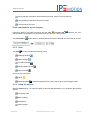
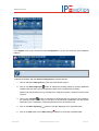
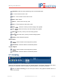
5.5 The main navigation tabs
The main navigation tabs allow a quick activation of the different main functions of IPEmotion. A tab
displayed in light blue indicates an active function.
IPEmotion is designed to follow the main navigation tabs from left to right. Use this reasonable order
like a read thread, which guides you step by step to a successful acquisition.
Project – Define your general user-defined project data.
Signals – Configure the connected acquisition systems and hardware modules.
Acquisition – Configure the desired storage groups and channels.
View – Take a measurement defined by the connected hardware modules and the set configurations.
Data manager – Manage your stored acquired data in all the supported formats.
Analysis – Visualize your channels with diagrams.
Scripting – Automate your acquisition sequences.
Info – Get a basic overview and general support.
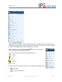
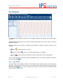
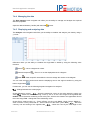
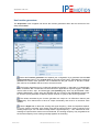
5.5.1 Info
The chapter offers a basic overview of the IPEmotion software. In addition, it shows useful advices
and tips and tricks on how to use IPEmotion.
IPEmotion
IPETRONIK GmbH & Co. KG
38/ 139
Getting Started
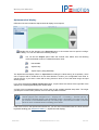
The view Info is divided into the following menu points:
Welcome
Release Notes (only in English)
Red thread
The main menu points (also called Main Navigation Tabs) allow you a clear and quick activation of
the different main part of IPEmotion. A light blue colored tab indicates an active main menu point.
IPEmotion is designed that way that you can follow the main navigation tabs from left to right. Use
this logical order like a red thread, which guides you step by step to a successful measurement.
Tips and tricks
This page offers useful tips and tricks to facilitate your start in IPEmotion and the work with the
software.
Keyboard handling
This page offers an overview about the keyboard navigation within the View and Analysis main
navigation tabs.
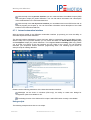
Customizing
Please find useful information about how to edit IPEmotion accordingly your specific requirements.
If you wish to receive more detailed information, the Expert mode is recommended. Activate this
mode within Options of the “Basic settings”. Extended levels of the configuration in the expert
mode are e.g.:
Setup tree includes more sub-nodes for some entries
Status channels show trigger status
Offset, amplitude, and frequency can be changed during measurement
The /ADP command line option is recommended for users who want to use IPEmotion with a
specific plugin. /ADP allows to use different instances (copies of given schemata) with different
application data. That means that the same IPEmotion version can be used with different plugin
combinations. This naturally includes all other application data, e.g. skin, user folders, hotkeys. To
use an IPEmotion version with different application data, proceed as follows:
Copy the existing IPEmotion application data folder of the corresponding version and
choose any name
Create a new desktop link to the IPEmotion version (e.g. by copying the existing desktop
link)
Add /ADP”Path of copy of application data folder\<Title>” to the target properties (space
before /ADP and quotation marks are mandatory, additional title is optional)
IPEmotion
IPETRONIK GmbH & Co. KG
39/ 139
Getting Started
Scripting
Edit IPEmotion accordingly your specific requirements and easily automate your process with the
automation interface in IPEmotion. The available interfaces depend on the acquired edition.
Documentations
Contact and support
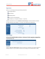
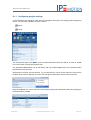
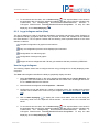
5.6 Getting Started
5.6.1 Launching IPEmotion
IPEmotion - Licensing
Launch
IPEmotion
from
the
menu
Start
→
Programs
→
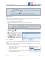
IPEmotion and enter a valid livense key in the IPEmotion – Licensing dialog.
IPETRONIK
→
Confirm your entry with Assign. The license information and all available version dependent
components are listed in the description field. Accept the activation of the license key with OK.
Exit the IPEmotion – License dialog with Close.
Logger selection
All detected data loggers are listed in the Logger selection dialog at starting IPEmotion. You have the
ability to select those loggers to access. To activate or deactivate the desired logger, click in the small
box of the Selection column.
The logger selection dialog is displayed by default and can be defined by using the IPEmotion
Options.
Select the menu point PlugIns within the IPEmotion Options
.
Select IPETRONIK LOG and click on the Settings button.
Within the Options tab you have the ability to define the Detection and Importing mode.
IPEmotion
IPETRONIK GmbH & Co. KG
40/ 139
Getting Started
Activate or deactivate the mode for detecting the data logger.
Logger with serial number
Selection by dialog
All loggers
Activate or deactivate the mode for importing the data from the logger.
Move (Select Move to copy and delete the data from the logger.)
Copy (Select Copy to copy the data from the logger.)
Activate within the General section the TESTdrive access restriction and/or the
encoding of the configuration files.
Confirm your selection with OK and close the IPEmotion Options dialog with OK.
IPEmotion
IPETRONIK GmbH & Co. KG
41/ 139
Getting Started
5.6.2 The automatic hardware detection
The dialog window Automatic hardware detection appears at opening IPEmotion for the first time.
Select the desired action for your next step and click on OK.
You have the ability to decide, if the selected action should always be taken at opening
IPEmotion. To activate this option, click the small box “Always operate the selected
action”. Please note that this option is only available if the hardware is already connected
and detected!
If the dialog window Automatic hardware detection should not be shown again at opening
IPEmotion, click the small box “Deactivate automatic hardware detection at start”.
The Automatic hardware detection screen allows you to safely and quickly use IPEmotion without
previous knowledge. It is an introducing help for simply and intuitively operating basic steps.
You can select one of the following actions:
Connect hardware and repeat detection
Guided and configuration step by step
Automatic configuration and displaying of data
Manual configuration of signals, acquisition and displaying
Change into simulation mode
No action
Connect hardware and repeat detection
Select the Connect hardware and repeat detection option and confirm with OK.
IPEmotion
IPETRONIK GmbH & Co. KG
42/ 139
Getting Started
Please note that this option is only available if no hardware is connected or an automatic detection of
the connected devices was not successful!
Guided and configuration step by step (User guidance)
The user guidance explains step by step how to create a project, define signals, operate an acquisition
and configure the displaying of the acquired data.
Each step to do is highlighted with a red background or red font color and points out the
step by step proceeding.
Select the Guided and configuration step by step option and confirm with OK.
First of all, enter in the appearing Project window a Project name and check the field Value entry for
Project name. Afterwards, enter a User and check the field Value entry for User. For detailed
descriptions of the project settings, please consult chapter 6.1 Project.
IPEmotion
IPETRONIK GmbH & Co. KG
43/ 139
Getting Started
The first step Project is then defined as completely done and marked with a green symbol.
Select the next step Signals to continue.
In the appearing Signals window create the desired system and check the field Create system(s).
Select components and check the field Add components. Define your channels and check the field
Configure channels. For detailed descriptions, please consult chapter 6.2 Signals.
The step Signals is then defined as completely done and marked with a green symbol.
IPEmotion
IPETRONIK GmbH & Co. KG
44/ 139
Getting Started
Select the next step Acquisition to continue.
In the appearing Acquisition window add a storage group and check the field Create storage
group(s). Select the desired channels and check the field Selection of channels to be saved. For
detailed descriptions, please consult chapter 6.3 Acquisition.
The step Acquisition is then defined as completely done and marked with a green symbol.
Select the next step View to continue.
In the appearing View window create pages/screens and check the field Create screen page(s).
Select the desired visual element and check the field Select type of visual element. Add your
channels and check the field Add channels. For adding the channels you have the ability to use the
Drag&Drop function. For detailed descriptions, please consult chapter 6.4 View.
The step View is then defined as completely done and marked with a green symbol.
IPEmotion
IPETRONIK GmbH & Co. KG
45/ 139
Getting Started
Confirm the appearing IPEmotion dialog with OK.
You can now start an acquisition and store the data. To do so, proceed as follows:
1. Click in the View menu on the button Start displaying
acquisition data.
2. Click on the button Start storing
IPEmotion
to start the displaying of the
to record the acquisition data.
IPETRONIK GmbH & Co. KG
46/ 139
Getting Started
Automatic configuration and displaying of data
Select the Automatic configuration and displaying of data option and confirm with OK.
The displaying starts automatically on the basis of the connected hardware. Click on the button Stop
displaying
to stop displaying the acqiured data.
Manual configuration of signals, acquisition and displaying
Select the Manual configuration of signals, acquisition and displaying option and confirm with
OK.
IPEmotion
IPETRONIK GmbH & Co. KG
47/ 139
Getting Started
You will find detailed information on how to use the manual configuration option and operate an
acquisition in chapter 5.7.2 The manual configuration.
Change into simulation mode
Select the Change into simulation mode option and confirm with OK. The simulation mode offers
you the possibility to start a Dry configuration.
You will find detailed information on how to use the simulation mode option and operate an acquisition
in chapter 5.7.2 The manual configuration.
Please note that this option is only available if no hardware is connected or an automatic detection of
the connected devices was not successful!
In addition, the simulation mode is set automatically as inactive at connecting and detecting hardware!
No action
Select the No action option and confirm with OK.
Select the No action option in combination with the activation of the setting Always operate the
selected action and IPEmotion operates an automatic hardware detection at every start. In this case,
the Automatic hardware detection screen is not shown again. Confirm with OK.
Please note that this option is only available if no hardware is connected or an automatic detection of
the connected devices was not successful!
IPEmotion
IPETRONIK GmbH & Co. KG
48/ 139
Getting Started
5.7 Three quick ways to a precise acquisition
You generate configurations with IPEmotion with little effort and acquire data with high precision.
IPEmotion offers you three different possibilities to generate configurations:
Automatic configuration
Manual configuration
Configuration by using a signal database
5.7.1 The automatic configuration
By using the automatic configuration the connected hardware devices are read and a configuration of
the signals is generated automatically.
The automatic configuration function requires that the hardware is connected to the
CANbus and active. If this is not the case, connect the desired devices to the CANbus of
your computer.
The command window Configuration is accessed through the Signals menu. With this command you
can select the active hardware platform.
IPEmotion
IPETRONIK GmbH & Co. KG
49/ 139
Getting Started
The displayed hardware system depends on your selected installation type.
To acquire data with the automatic configuration proceed as follows:
1. Click in the menu Project on the AUTO generation
configuration generation process.
button to start the automatic
2. After the successful detection of hardware and initialization, the connected hardware devices
are shown in the menu View.
3. Click in the menu View on the Start displaying
data.
4. Click on the Start storing
button to start displaying the acquisition
button to record the acquisition data.
5.7.2 The manual configuration
The manual configuration offers you the ability to make specific modifications of the acquisition
devices.
The manual configuration function requires that the hardware is connected to the
CANbus and active. If this is not the case, connect the desired devices to the CANbus of
your computer.
First of all, define your project and enter in the Project window a project name and a user name
afterwards.
IPEmotion
IPETRONIK GmbH & Co. KG
50/ 139
Getting Started
In the Signals menu is the command window Configuration. You can now select the active hardware
platform.
The displayed hardware system depends on your selected installation type.
To take an acquisition with the manual configuration proceed as follows:
1. Click on the button Add system to open select the desired system.
2. Click on the Add component
button to expand the existing system by showing additional
hardware devices and to set the respective number of the corresponding modules.
Please note that the button is only activated if the respective system is selected in the window
Systems.
button to initialize the hardware and to synchronize and configure
3. Click on the Initialize
the selected system on the basis of the data. At the hardware initialization the devices are
switched into the configuration mode and following into the acquisition mode.
4. Click on the Start displaying
button to start the displaying of the acquisition data.
5. Click in the View menu on the Start storing
IPEmotion
button to record the acquisition data.
IPETRONIK GmbH & Co. KG
51/ 139
Getting Started
5.7.3 The configuration using a signal database
IPEmotion offers you the ability to load a signal database from user-defined files or databases. To
access a specific signal database in IPEmotion the signal database must be converted to an
IPEmotion file format.
The conversion can be done with an external program. These user-defined programs are easily
generated on request and offer the ability to import signal channels into IPEmotion.
First of all, you have to define the basic setting of IPEmotion to use the configuration with signals.
or open the dialog window IPEmotion Options by using the application menu
Click on Options
and the Options function. In the Basic settings section select the configuration type Signals
configuration and the desired signal database (*.mpc). Confirm with the OK button.
To create a configuration with a signal database proceed as follows:
1. In the Signals menu click in the window Signals.
2. Under the point Signals click on the Import button
and select the Signal import.
3. Open the desired signal database (*.mpc) and select the desired signals by using a filter or
multiple selections. Assign the signals with Drag&Drop or by using the arrow buttons.
4. Select the desired hardware in the Components column.
The available hardware components are based on the assigned priority of the
system settings within the IPEmotion → PlugIns → Settings.
This preselection of the system components facilitates the device selection and
improves the system speed.
Confirm with OK.
5. Click on the Start displaying
button to start the displaying of the acquisition data.
6. Click in the Acquisition menu on the Start storing
IPEmotion
IPETRONIK GmbH & Co. KG
button to record the acquisition data.
52/ 139
Working with IPEmotion
6 Working with IPEmotion
The following chapter shows how to use the software IPEmotion for configuring the hardware modules
and acquiring data, as well as, managing and analyzing the acquired data.
6.1 Project
The increasing number of units in operation and the ever increasing amount of data being captured
requires an ability, which offers you a simple and flexible solution. IPEmotion provides a method,
which guarantees the simple and intuitive management of all acquired data. This concept is based on
the definition of relevant and significant parameters and their relationship to the Project settings,
which are saved in an acquisition data file.
IPEmotion offers you the ability to create user-defined projects. These projects contain general
parameters needed to define fundamental information for an acquisition. The project settings allow a
clear, structured view and management of road tests and multiple data acquisitions. Based on these
user-defined projects, data analysis and statistical reports are made possible.
The basis for defining the project settings are the two description files projectPar.xml and
projectData.xml. With using those project description files and any text or HTML editor, you can define
default and user-defined parameters and the corresponding values.
The project properties are controlled with the parameters of the above mentioned XML files.
The input fields using the IPEmotion user interface are defined as freely editable by default.
The default setting of the project properties in IPEmotion refers to the language dependent column
Name. This column Name refers to the user-defined parameter descriptions and is therefore nameoriented.
Please note that using the name-oriented project settings; only the properties can be tracked within
the acquisition data file.
IPEmotion
IPETRONIK GmbH & Co. KG
53/ 139
Working with IPEmotion
6.1.1 Configuring project settings
In the IPEmotion user interface, under the main navigation tab Project, all existing project settings are
shown. The overview is divided into three columns:
Name
Value
The user-specific data of the Name column include information about the vehicle, as well as, details
from to the author of the project and the user.
The parameter Value allows you to add and/or edit own project-related notes and comments within
the IPEmotion user interface.
With using the Column Chooser function, you can add the Key column to this overview. Click into the
headline of the column and open the menu with the right mouse button. Select Column Chooser.
Drag the available Key column from the Customization dialog into the desired position by keeping the
left mouse button pressed.
IPEmotion
IPETRONIK GmbH & Co. KG
54/ 139
Working with IPEmotion
The division into the two project description files projectPar.xml and projectData.xml was
required to separate the definition of the project properties from the real values. For
purposes of clarity, projectPar.xml contains the definition of the project parameter and
projectData.xml the corresponding values. You have the ability to automatically update
those values (projectData.xml) by using a database without influencing or changing the
project definition (projectPar.xml).
The parameter Name and Key can be configured and defined by using the files projectPar.xml and
projectData.xml. These configuration files for the project settings can be found in the following user
directory: Windows XP: C:\Documents and Settings\zw\Application data\IPETRONIK\IPEmotion
Vxx.xx\ProjectTemplate;
Windows
7:
C:\Users\All
Users\IPETRONIK\IPEmotion
Vxx.xx.xx\ProjectTemplate\.
6.2 Signals
Systems
Channels
Configuration dialogs
Click on the Add system button to select the active hardware platform. This concept allows the
support of any hardware (also from third parties). Actual plugins are: IPETRONIK CAN, IPETRONIK
LOG, and CAN.
The available hardware systems of the signals main navigation tab depend on the
activated hardware.
Please find further information on how to activate the used hardware systems by using the
IPEmotion Options in chapter 5.3.1 (PlugIns).
After the successful automatic hardware detection at starting IPEmotion, all available systems,
modules, and the channels with the respective properties are listed under the main navigation tab
Signals. The overview is divided into the following three sections:
IPEmotion
IPETRONIK GmbH & Co. KG
55/ 139
Working with IPEmotion
Systems
Channels
Configuration dialogs
6.2.1 Systems
The view Systems contains all available systems and the corresponding modules with the respective
type description and channel count.
At using the manual configuration of the connected systems click on the button Detect
. The
hardware detection starts on the basis of the connected devices and the data is shown in the
overview.
At manually creating a configuration for the Dry configuration proceed as follows:
1. Click on the button Add system and select the desired hardware.
to expand the existing system by further
2. Click on the button Add component
components and to set the respective number of the corresponding modules.
Please note that the button is only activated if the respective system is selected in the window
Systems!
to initialize the hardware and to synchronize and configure
3. Click on the button Initialize
the selected system on the basis of the data. At using the hardware initialization the devices
are switched into the configuration mode and acquisition mode.
The data is shown in the overview. At manually adding the connected IPETRONIK CAN devices the
CAN-ID starts at 10 by default and the serial number is set to 99999.
At acquiring data by using an ETHERNET cable and a data logger that was previously
configured with the IPEconf 4 software, the following error message may appear:
“The logger configuration was created with IPEconf 4 and cannot be read. A logger with 2
CAN interfaces is set.”
To being able to use the corresponding data logger in IPEmotion, you need to download a
default configuration to the data logger. To do so, proceed as follows:
Click on the New
button to create a new configuration.
Select the data logger according to the connected hardware by using the Add
system
and Add components
buttons.
Configure the data logger:
Select the data logger in the system view and assign the Front number
within the Extended tab. The front number consists of the last 4-5 digits.
Activate for instance a DIN channel.
IPEmotion
IPETRONIK GmbH & Co. KG
56/ 139
Working with IPEmotion
Add a new storage group to the local storage groups and add the
activated channel.
Click on the Initialize
configuration.
Click on the Detect
button to update the connected hardware with the new
button and select the desired data logger.
The data logger with the initialized configuration is shown in the IPEmotion user interface.
TEDS sensors
IPEmotion V01.09 (in combination with e.g. IPEmotion PlugIn IPETRONIK X V01.03) allows using
TEDS sensors (Transducer Electronic Data Sheet).
To work with TEDS sensors, proceed as follows:
Connect the module to a Lemo 2B port (10-pin) of a suitable module.
Connecting and disconnecting of a TEDS sensor is automatically detected by IPEmotion and shown in a popup message, as well as, within the message window. The
Symbol column within the channel overview identifies the connected TEDS sensors
whose data is automatically set for the channel.
Select the Detect
function to read out the sensor and scale with predefined data or the
Synchronize
function.
After reading out the sensor and activating the corresponding channels, you
can use the tab Scaling -> Scaling calculator or the context menu -> Scaling calto display the sensor informaculator
tion. The entry mode TEDS Sensor is
automatically selected.
6.2.2 Channels
The view Channels contains all available channels of the device selected in the tree list of the systems
section.
With the Column Chooser function, IPEmotion offers you the ability to use your own user-defined
columns. To do so, proceed as follows:
1. Click into the headline of the column and open the menu
with the right mouse button.
2. Select Column Chooser.
3. Drag the desired columns into the view window by keeping
the left mouse button pressed.
IPEmotion
IPETRONIK GmbH & Co. KG
57/ 139
Working with IPEmotion
6.2.3 Configuration dialogs
The view Configuration dialogs contains all configuration possibilities of the systems or device
selected in the tree list of the systems section.
The shown configuration tabs are based on the selected system or device and channel. For a system
you can for example define the following settings:
General
CAN hardware
Options
For a device you can for example set the following options:
General
Extended
Information
The options for a channel are based on the selected device. You can for example define the following
settings:
General
Format
Scaling
Display
Offset
Sensor
Filter
Adjust
For working with data loggers, IPEmotion offers you the ability to define the limit
values of an acquisition. There are visual and auditory signals for controlling the limits
available. Define the settings by using the Limit value tab. Clicking in the Min-Max
List selection box, you activate the creation of a *.STG file where the global minima
and maxima of the corresponding channels are stored.
IPEmotion
IPETRONIK GmbH & Co. KG
58/ 139
Working with IPEmotion
6.2.4 Using the scaling calculator
IPEmotion offers you the ability to define the sensor range and acquisition mode of a channel by using
the scaling calculator. Calculate the physical range and the acquisition range of your data.
A precondition for using the scaling calculator is the selection of channels in your configuration. Start
the scaling calculator by using the corresponding button within the Scaling tab .
The scaling calculator offers you the following four input modes:
2-point scaling
Free 2-point scaling
Factor/Offset scaling
Multipoint scaling
STG
Active/Passive sensors
TEDS Sensor
The section Channel settings offers you to define the physical unit of the channel.
IPEmotion
IPETRONIK GmbH & Co. KG
59/ 139
Working with IPEmotion
2-point scaling
The acquisition range is already set by the channel properties. Define the physical range.
Free 2-point scaling
In addition, define the ordinates in the acquisition range.
Factor/Offset scaling
Define the calculating and scaling factors within the linear equation.
Multipoint scaling
Define individual nodes for nonlinear sensor scaling with the respectively assigned physical values.
The nodes can be entered manually or the current measurement value can be requested from the
device for every node.
Use the ٭character to add or delete a node within the overview Physical value and Acquisition value. To accept the acquisition value, a previous test acquisition is required. The Apply
measured value button is then activated.
The multipoint scaling is only supported for acquisitions directly in IPEmotion.
STG
Define your STG values for STG capable channel types to start an automatic calculation of the
acquisition range with additional strain conversion. You can additionnally check your configured STG
bridge.
Click on the Calculate optimal shunt resistance button or the Shuntcheck button to run an
acquisition. This result is compared to the precalculated expected value. If the resulting value
differs considerably from the expected value, which has been defined by a tolerance level, a
corresponding warning is displayed.
TEDS Sensor
Use the TEDS sensors (Transducer Electronic Data Sheet) for automatic detection and configuration
of data acquisition systems (see TEDS sensors).
6.2.5 Using the sensor data base
The sensor data base in IPEmotion offers information about any count of sensors. For example, the
following relevant data of a sensor are saved:
Name
Type
IPEmotion
IPETRONIK GmbH & Co. KG
60/ 139
Working with IPEmotion
Acquisition range
Scaling and linearization information
Adjusting date
It is embedded into the scaling calculator for allowing a quick configuration of known sensors.
The sensor data base can contain various information of a sensor. Two different application cases
may be distinguished for the specification of the data to be saved in principle:
only the sensor type in the data base is described
a special sensor in the data base is described
In the first case, the sensor data base only includes basic information about the sensor types and the
following descriptions for instance are not saved in the data base:
Calibration date
Serial number
Storage location
This model requires only a few descriptions and does not force the possibility to change data in the
data base. The first case is recommended for working with a small number of sensors and if no fixed
assignations of single sensors to application areas are set. A special advantage is the considerably
shorter list of sensors in the data base, as well as, the unique assignation of a sensor to a data base
entry via the sensor type.
By contrast, the second case also includes the storage of data, which are not specified in the first
case. Therefore, the data base can contain any number of sensors of the same type, which for
instance only differ in the serial number. The second model is recommended for working with bigger
systems with fixed assignations – in spite of the higher maintenance requirements (changes at the
sensors like entering the calibration date into the data base.)
The IPETRONIK sensor data base is separated into two linked data base tables. This concept allows
the access to the general data of a sensor type, as well as, to the data of a specific sensor from the
data base. The first table includes all constant data of a sensor type. The second table includes all
data of a specific sensor. They additionally include a reference at the sensor type, which belongs to
the sensor. The second table is primarily used if single sensors with scaling and linearization
information should be stored in the sensor data base.
The table 1 includes for example the following data:
Sensor type (Name)
Sensor model
Manufacturer
Type of the output signal (Excitation, Current, Frequency,…)
IPEmotion
IPETRONIK GmbH & Co. KG
61/ 139
Working with IPEmotion
Physical unit
Minimum / Maximum physical value
Output unit (Excitation/Current/Frequency/…)
Minimal / Maximal output excitation/current/frequency/…
Supply excitation (nominal)
Excitation minimal / maximal
Sensitivity
Bridge resistance
k-factor
Bridge factor
Poisson’s ratio
Maximal current
The table 2 includes for example the following data:
Serial number
Calibration date
Additional information about the single sensors can be stored by using a user-defined list in the XML
format. This type of information includes for example the sensor precision, overload limit, sensor type
and the working temperature range. Please note that these data do not flow into the scaling
calculation.
The data base format
The sensor data base in the IPEmotion version was created in the XML format. At the installation of
IPEmotion, the IPESensorDatabase file is stored in the following directory: Windows XP:
C:\Documents and Settings\UserApplication data\IPETRONIK\IPEmotion Vxx.xx\Database; Windows
7: C:\ProgramData\IPETRONIK\IPEmotion Vxx.xx.xx\Database.
the following extract shows the structure of the data base:
<?xml version="1.0" encoding="utf-8"?>
<SensorDatabase version="1">
<!-- GIGATRONIK -->
<Sensor name="GTF20midi">
<sensorName type="String">GTF20midi</sensorName>
IPEmotion
IPETRONIK GmbH & Co. KG
62/ 139
Working with IPEmotion
<sensorTypeId type="Int32">3</sensorTypeId>
<sensorType type="String">Shunt</sensorType>
<sensorManufacturer type="String">GIGATRONIK</sensorManufacturer>
<physicalUnitName type="String">A</physicalUnitName>
<physicalMin type="Double">0</physicalMin>
<physicalMax type="Double">20</physicalMax>
<outputUnitName type="String">V</outputUnitName>
<outputMin type="Double">0</outputMin>
<outputMax type="Double">2</outputMax>
<UserProperties>
<UserProperty>
<propertyName type="String">Working temperature range</propertyName>
<propertyValue type="String">-40 … +85 °C</propertyValue>
</UserProperty>
<UserProperty>
<propertyName type="String">Precision</propertyName>
<propertyValue type="String">± 1%</propertyValue>
</UserProperty>
</UserProperties>
<SpecificSensors>
<SpecificSensor>
<serialNumber type="String"></serialNumber>
</SpecificSensor>
<SpecificSensor>
<serialNumber type="String">SN #1</serialNumber>
<calibrationDate type="Date">2007-10-01</calibrationDate>
<CalibrationValidDuration>
<calibrationValidYears type="Int32">0</calibrationValidYears>
<calibrationValidMonths type="Int32">6</calibrationValidMonths>
<calibrationValidDays type="Int32">10</calibrationValidDays>
</CalibrationValidDuration>
<physicalMin type="Double">0.1</physicalMin>
<physicalMax type="Double">19.8</physicalMax>
<outputMin type="Double">0.01</outputMin>
<outputMax type="Double">1.98</outputMax>
</SpecificSensor>
The sensor names (“sensorName”) must be unique!
The current version of the sensor data base includes the following defined values for the
“sensorTypeId” entry:
IPEmotion
IPETRONIK GmbH & Co. KG
63/ 139
Working with IPEmotion
UNKNOWN = 0,
DisplacementTransducer = 1,
LoadCell = 2,
Shunt = 3,
CurrentTransformer = 4,
VoltageTransformer = 5,
ForceTransducer = 6,
PressureTransmitter = 7,
AbsolutePressureTransmitter = 8,
GaugePressureTransmitter = 9,
DifferentialPressureTransmitter = 10,
FlowRateTurbine = 11,
PistonFlowmeter = 12,
ScrewFlowmeter = 13,
VortexSheddingDevice = 14,
Accelerometer = 15,
TriAxialAccelerometer = 16,
TorqueMeter = 17,
Counter = 18,
StrainGauge = 19,
LVDT = 20,
StrainGaugeBridge = 21,
TemperatureSensor = 22,
// Displacement transducer
// Load cell
// Shunt
// Current transformer
// Voltage transformer
// Force transducer
// Pressure transmitter
// Absolute pressure transmitter
// Gauge pressure transmitter
// Differential pressure transmitter
// Flow rate turbine
// Piston flow meter
// Screw flow meter
// Vortex shedding device
// Accelerometer
// Triaxial accelerometer
// Torque meter
// Counter
// STG
// LVDT
// STG bridges (Strain)
// Temperature sensor
If non of the predefined types meets your requirements, you can add user-defined types to the sensor
data base. The “sensorTypeId“ value must be set to 0. A short description text should classify the
corresponding sensor.
If you want to use several exemplars of a sensor within the sensor data base, use the
“SpecificSensors” entry. Each of the sensors must get an unique serial number (“serialNumber”). In
addition, each of these exemplars can get a calibration date (“calibrationDate”), as well as, a period of
validity of the calibration (“CalibrationValidDuration”) including the data “calibrationnValidYears”,
“calibrationValidMonths”, and “calibrationValidDays”. Furthermore, the values for "physicalMin",
"physicalMax", "outputMin", and "outputMax", which can be found in the data sheet, can be overwritten
by values, which are read at the calibration.
You can add non-relevant information for the functionality of the sensor data base like the working
temperature range under the “UserProperties” entry. These are Key/Value pairs, which are used for
displaying the information. Please note that these data are not used in any calculation.
6.2.6 The Import function
The import functionality in IPEmotion offers you the ability to import one or several signals and to assign a sampling rate. The proceeding configuration takes place after the import in IPEmotion.
The Synchronize
button allows to adjust the current description file with a newer version
of this file. Activate the Show differences option to display potential deviations of both files.
IPEmotion
IPETRONIK GmbH & Co. KG
64/ 139
Working with IPEmotion
CANdb, A2L, UDS
Using the Import function in IPEmotion, you have the ability to read description files for the
configuration of an acquisition. By doing so, control unit description files for example are imported with
the A2L format and vehicle data like air conditioning or seat adjusting with the CANdb format.
To use the Import function in IPEmotion, proceed as follows:
Using the Signals main navigation tab, select the hardware with the desired port, e.g. CAN,
LIN, FlexRay.
Select the input and click on the button Import
CANdb
, A2L
, UDS
. Select importing from the desired file, e.g.
.
The dialog window Open file will be initialized.
Select from the dialog window Open file the desired description file (*.dbc/*.ldf/*.a2l/*.xml)
with the channels to be imported. If the description file includes several protocols, please select
the desired one.
Using the Open button, the description file will be imported and all included channels are
listed in the left overview of the dialog window CANdb import/A2L import/UDS import.
Select the desired channels or click Select all. Confirm the selected signals using the OK
button. Following the progress bar, the imported channels are listed in IPEmotion.
DAQ lists
The A2L import dialog offers you the ability to import protocols including DAQ lists (e.g. CCP, XCP).
You can assign preferred sampling rates to your signals. Please note that the selection of the sampling rate and the corresponding DAQ list is subjected to the following conditions and definitions:
The signal is assigned to the corresponding DAQ list depending on the selected sampling
rate, whereas time-synchronized DAQ lists are defined with a higher priority than angularsynchronized DAQ lists.
IPEmotion
IPETRONIK GmbH & Co. KG
65/ 139
Working with IPEmotion
If no DAQ list with the desired sampling rate is available, a DAQ list with higher sampling rate
is used.
If the selected sampling rate is higher than all offered sampling rates of the available DAQ
lists, the fastest DAQ list is used.
If no DAQ list is defined, the Polling DAQ list is used.
You can also explicitly assign the signals to a single DAQ list. To do so, show the DAQ list column
within the import dialog. This mode allows to directly assign the DAQ list to be used to the signals.
Proceed as follows:
Select the Column Chooser
the column heading.
entry within the A2L import dialog from the context menu of
Drop the DAQ list entry from the Customization dialog to the desired position within the column heading. This action automatically removes the Sampling rate column.
If you want to activate more signals than available in a DAQ list, the overfilling is indicated as a warning in the view tree. At overfilling a DAQ list, the corresponding signals are automatically deactivated
after import. IPEmotion offers you the ability to check the filling level of the DAQ lists.
ties
Open the context menu of the desired DAQ list in the tree view and open the Import properentry.
The import properties show an overview about e.g. the percentage filling level or the number of
free signals for a specific data type. If the DAQ list is overfilled, the number of signals to be removed is indicated with a negative figure.
Please note that the import properties are only available with the Expert mode! Activate this mode
within IPEmotion options
-> Basic settings -> Expert mode.
Diagnosis
Using the function Import in IPEmotion, you have the possibility to read description files for the
configuration of an acquisition. Import all control units description files from the file format *.idf. This file
is based on the description language XML and contains additionally to the control unit information the
diagnostic jobs to be run. You define the job sequences of a specific control unit (ECU). The job
sequences are a group of single jobs (services) and their defined order.
To use the function Import for diagnostic jobs in IPEmotion, proceed as follows:
Using the Signals main navigation tab, select the hardware with a CAN port.
Select the CAN input and click on the button Import
file
. Select importing from a Diagnostics
.
The dialog window Open file will be initialized.
Select from the dialog window Open file the desired description file (*.idf) with the job
sequences to be imported.
IPEmotion
IPETRONIK GmbH & Co. KG
66/ 139
Working with IPEmotion
Using the OK button, the file will be imported and all included job sequences are listed in the
channel overview in IPEmotion.
6.2.7 Configuration with signal database
The use of signal databases allows a signal oriented configuration. IPEmotion offers you the ability to
load a signal database from user-defined files or databases.
If you have an own signal database available, you can import it to IPEmotion and select your signals.
To access a specific signal database in IPEmotion the signal database must be converted to an
IPEmotion file format. The conversion can be done with an external program. These user-defined
programs are easily generated on request and offer the ability to import signal channels into
IPEmotion.
The signals of a database are assigned to signal groups and signals, in which the affiliation of signals
to a signal group decides about the possibility of using several signals on one remote device.
The order of the found hardware is sorted according to the fitness for use. IPEmotion sorts the
hardware in descending order accordingly to their fitness.
The following criteria are considered for sorting the hardware accordingly to the importance:
Sensor mode
Sensor range (differential consideration)
Priority
IPEmotion offers the possibility to influence the order. The available hardware components are based
on the assigned priority of the system settings within the IPEmotion → PlugIns → Settings. This
preselection of the system components facilitates the device selection and improves the system
speed.
First of all, you have to define the basic setting of IPEmotion to use the configuration with signals.
or open the dialog window IPEmotion Options by using the application menu
Click on Options
and the Options function. In the Basic settings section select the configuration type Signals
configuration and the desired signal database (*.mpc). Confirm with the OK button.
To create a configuration with a signal database proceed as follows:
1. In the Signals menu click in the window Signals.
2. Under the point Signals click on the Import button
and select the Signal import.
3. Open the desired signal database (*.mpc) and select the desired signals by using a filter or
multiple selections. Assign the signals with Drag&Drop or by using the arrow buttons.
4. Select the desired hardware in the Components column. Confirm with OK.
5. Click on the Start displaying
button to start the displaying of the acquisition data.
6. Click in the Acquisition menu on the Start storing
IPEmotion
IPETRONIK GmbH & Co. KG
button to record the acquisition data.
67/ 139
Working with IPEmotion
Structure of a signal database
Files for signal databases are XML files (*.mpc). The schema file Mpc.xsd is available for validating
MPC files and is installed in the following directory: Windows XP: C:\Documents and
Settings\User\Application data\IPETRONIK\IPEmotion Vxx.xx.xx\template; Windows 7: C:\Users\All
Users\IPETRONIK\IPEmotion Vxx.xx.xx\template.
A signal contains the following parameters:
Name
Type
Description
group
string
Signal group
point
string
Signal
sensorMode
uint32
Sensor mode (see following table)
sensorMin
double
Min limit of the sensor range
sensorMax
double
Max limit of the sensor range
sensorUnit
string
Sensor unit for elements with the sensor mode
“undefined”
sampleRate
double
Sampling rate in Hz (optional)
The following sensor modes are currently available:
Name
Value
Description
NoUnit
0x00000000
Signal without unit
Status
0x00010000
Status signal
EventCounter
0x00020000
Event counter
Length
0x00000001
Length
Mass
0x00000002
Mass
Time
0x00000003
Time
PeriodicDuration
0x00010003
Periodic duration
PulseDuration
0x00020003
Pulse duration
PauseDuration
0x00030003
Pause duration
TimingOffset
0x00040003
Time offset
Current
0x00000004
Current
CurrentWithSens
0x00010004
Current including sensor excitation
Temperature
0x00000005
Temperature
Thermocouple
0x00010005
Thermocouple
Pt100
0x00020005
PT-100
Pt200
0x00030005
PT-200
Pt1000
0x00040005
PT-1000
MolarAmount
0x00000006
IPEmotion
IPETRONIK GmbH & Co. KG
68/ 139
Working with IPEmotion
LuminousIntensity
0x00000007
Voltage
0x00000008
Sens
0x00010008
Stg
0x00020008
Icp
0x00030008
Resistance
0x00000009
Frequency
0x0000000A
FrequencyFromPeriod 0x0001000A
Force
0x0000000B
Energy
0x0000000C
Power
0x0000000D
Pressure
0x0000000E
Speed
0x0000000F
Rpm
0x00000010
MassFlowRate
0x00000011
Angle
0x00000012
Strain
0x00000013
BaudRate
0x00000014
Percent
0x00000015
DutyCycle
0x00010015
ByteSpace
0x00000016
Undefined
-1
IPEmotion
IPETRONIK GmbH & Co. KG
69/ 139
Working with IPEmotion
6.3 Acquisition
In the Acquisition main navigation tab all available channels are shown. You can configure
calculations and create storage groups.
If a storage group contains channels with only one storing rate, i.e. all channels have the
same storing rate, one time channel is created for all channels of the storage group.
If a storage group contains channels with different storing rates, one time channel is
created for each channel of the storage group.
IPEmotion offers the ability to save the acquired data in different formats.
Create a storage group and add the desired channels to the Included channels overview.
Select in the Saving tab of the configuration dialogs the desired format.
Create another storage group and repeat the above steps.
Please note the maximum file size of approx. 454 MB. If this file size is reached, the
corresponding file is closed and a new file is created. An ascending index counting is used
for describing the generated files.
The Drag&Drop function or the Selection or All buttons from the view Available channels can be used
to display the desired channels in the view Included channels.
IPEmotion
IPETRONIK GmbH & Co. KG
70/ 139
Working with IPEmotion
Define how to measure and store the configured channels (e.g. triggered, continuously and in which
storage group). To do so, use the setting possibility Storage within the configuration dialogs.
To acquire data, the acquisition storage has to be started and stopped manually or triggered to start.
A potential PC overload can result in a stop of displaying the data. But the recording and
saving of the data continues. Due to the fact that an acquisition has the highest priority, it
can be ensured that the data transfer is sustained and no data is lost.
6.3.1 Saving
IPEmotion offers the ability to configure important dates in the measurement files by using markers.
Optional texts can also be defined.
Select the Acquisition main navigation tab and the Saving
entry within the tree view.
Subsequently select the Saving tab in
the configuration dialogs and activate the
Marker function. You can define a name
for this marker. If a marker is activated, it
is automatically added to the list of the
channels to be stored.
You can additionally assign a hotkey for a
marker.
Open the IPEmotion options
and the Hotkey entry.
Open the Area: Acquisition entry
and double-click on AcquisitionStorage group-Marker. Assign a hotkey for this new command. Select the
corresponding marker in the Entry
column. Confirm your configuration with OK.
At using the hotkey, the text (if defined) is set with
the time stamp. If the associated storage group is stored at the same time, the date is also saved
for this process.
Storage group
IPEmotion offers you the ability to track the current
status of a storage group. Depending on your configuration of the storage mode (Storage configuration tab), the
current status is shown within the Saving window.
The following modes are currently available:
Offline, Pre-trigger phase, Storage, Waiting for trigger
IPEmotion
IPETRONIK GmbH & Co. KG
71/ 139
Working with IPEmotion
6.3.2 Formula editor
The formula editor allows a simple use and displaying of mathematic and physical functions and
formulas. The following chapter shows entry examples of the available functions and formulas.
The calculation results are automatically written into the formula channel (result channel) at using the
formula editor.
Function
Example
Editor entry
Addition
Value1 + Value2 “Temp_1“+”Temp_2”
= Result1
Subtraction
Value1 - Value2 = “Temp_1“-”Temp_2”
Result1
Multiplication
Value1 * Value2 = “Temp_1“*”Temp_2”
Result1
Division
Value1 / Value2 = “Temp_1“/”Temp_2”
Result1
MOD
17 mod 3 = 2
"Sens_channel1"MOD"Sens_channel2"
- The modulo function (remainder) shows the remainder of a division of two integers.
ABS (-17) = 17
ABS
ABS("SENS_channel3")
- The amount function converts a negative value into a positive one.
Sign
(-3786) SIGN("DMS_channel8")
return value: -1
"Temp_2")
SIGN
or
SIGN("Temp_1"-
- The SIGN function returns the sign of the numeric term, which is written in brackets.
Depending on the read number, the function returns the values as follows:
At negative numbers, SIGN returns –1.
At positive numbers, SIGN returns 1.
At zero, SIGN returns 0.
Equal
Temp_1 = 70
“Temp_1”=70
- The operator compares the values on the left and right side of the equal sign. The return
value is 1 in compliance, otherwise 0.
Unequal
Temp_1 <> 70 "Temp_1"<>70
return value 1
- Value1 is compared with value2. If the values do not comply, the return value is 1,
otherwise 0.
Greater than
IPEmotion
3000 > 2 return "Temp_1">"Temp_2"
value 1; 200 >
4000 return value
0
IPETRONIK GmbH & Co. KG
72/ 139
Working with IPEmotion
- The value1 left to the sign is compared with the value2 right to the sign. If value1 is greater
than value2, the return value is 1.
Less than
3000 < 2 return "Temp_1"<"Temp_2"
value 0; 200 <
4000 return value
1
- The value1 left to the sign is compared with the value2 right to the sign. If value1 is less
than value2, the return value is 1.
Greater equal
30 >= 5 return "Temp_1">="Temp_2"
value 1; 40 >= 50
return value 0
- The value1 left to the sign is compared with the value2 right to the sign. If value1 is greater
than or equal to value2, the return value is 1.
Less equal
30 <= 5 return "Temp_1"<="Temp_2"
value 0; 50 <= 50
return value 1
- The value1 left to the sign is compared with the value2 right to the sign. If value1 is less
than or equal to value2, the return value is 1.
PREV
Prev(Thermo_cha PREV(“Thermo_channel2”)
nnel2)
- The PREV function allows the displaying of prior measuring values. After having selected
the channels, the values of the previous cycle are shown (n=n-1).
SIN(),
COS(),
TAN(), SINH(),
COSH(),
TANH(), ASIN(),
ACOS(), ATAN()
- All trigonometric functions are calculated in radians (0 … 2*Pi). At invalid values,
NoValue/invalid is written into the result channel.
NOT
Signal A = 0, NOT("Status_1")
Output = 1; Signal
A = 1, Output = 0
- The output inverts the logical status of the input. Status of previous logical channels can
also be inverted.
"Signal A"AND"Signal B"
AND
- At least two channels are compared.
"Signal A"OR"Signal B"
OR
- At least two channels are compared.
XOR
"Signal A"XOR"Signal B"
- At least two channels are compared. In contrast to Or, only one input can have the logical
status 1 for getting a logical 1 at the output.
IPEmotion
IPETRONIK GmbH & Co. KG
73/ 139
Working with IPEmotion
EXP("Channel")
EXP
- At invalid values of the exponential function, NoValue/invalid is written into the result
channel.
LOG("Channel")
LOG
- At invalid values of the logarithm function, NoValue/invalid is written into the result channel.
LN("Channel")
LN
- At invalid values of the natural logarithm function, NoValue/invalid is written into the result
channel.
SQRT("Channel")
SQRT
- At invalid values of the square root function, NoValue/invalid is written into the result
channel.
SIGN("Temp_1"-(PREV("Temp_1")))
Tendency
displaying
- The result is 1 at rising temperature and –1 at decreasing temperature.
Gliding
averaging of
the last 5
values
MEAN("Temp_1"; 5)
Logical
connection of
several
channels
(("Temp_1"+"Temp_2")>60)AND(("Temp_3"+"Temp_
4")>50)
Operators
This section shows the currently available operators and their syntax and behavior referring to NoValues.
A formula is parsed case-sensitively.
Operator Description
Syntax
NaN
+
Addition of two operands
Op1 + Op2
(Op1 == NaN) ||
(Op2 == NaN)
-
Subtraction of two operands
Op1 – Op2
(Op1 == NaN) ||
(Op2 == NaN)
*
Multiplication of two operands
Op1 * Op2
(Op1 == NaN) ||
(Op2 == NaN)
IPEmotion
IPETRONIK GmbH & Co. KG
74/ 139
Working with IPEmotion
/
Division of two operands
Op1 / Op2
(Op1 == NaN) ||
(Op2 == NaN) ||
(Op2 == 0.0)
^
Potentiation of two operands
Op1 ^ Op2
(Op1 == NaN) ||
(Op2 == NaN)
=
Analysis of two operands for equality
Op1 = Op2
(Op1 == NaN) ||
(Op2 == NaN)
!=
<>
Analysis of two operands for inequality
Op1 != Op2
(Op1 == NaN) ||
(Op2 == NaN)
<
Analysis of two operands for less
Op1 < Op2
(Op1 == NaN) ||
(Op2 == NaN)
<=
Analysis of two operands for less or
equal
Op1 <= Op2
(Op1 == NaN) ||
(Op2 == NaN)
>
Analysis of two operands for greater
Op1 > Op2
(Op1 == NaN) ||
(Op2 == NaN)
>=
Analysis of two operands for greater
or equal
Op1 >= Op2
(Op1 == NaN) ||
(Op2 == NaN)
ABS
Absolute value
ABS(Op1)
(Op1 == NaN)
ACOS
Arcus cosine
ACOS(Op1)
(Op1 == NaN)
AND
Logical And operator (&&)
Op1 AND Op2
(Op1 == NaN) ||
(Op2 == NaN)
ANDB
Bitwise And operator (&)
Op1 ANDB Op2
(Op1 == NaN) ||
(Op2 == NaN)
ASIN
Arcus sinus
ASIN(Op1)
(Op1 == NaN)
ATAN
Arcus tangent
ATAN(Op1)
(Op1 == NaN)
CEIL
Sends the less integer value, which is
greater than or equal to the value of
Op1.
CEIL(Op1)
(Op1 == NaN)
COS
Cosine function
COS(Op1)
(Op1 == NaN)
COSH
Cosine Hyperbolicus
COSH(Op1)
(Op1 == NaN)
DIFF
(Op1(t) – Op1(t-1)) / DeltaT
DIFF(Op1)
(Op1 == NaN)
EDGE_N Detection of negative edges of Op1.
EG
EDGE_NEG(Op1)
(Op1 == NaN)
EDGE_P Detection of positive edges of Op1.
OS
EDGE_POS(Op1)
(Op1 == NaN)
EXP
EXP(Op1)
(Op1 == NaN)
IPEmotion
Exponential function
IPETRONIK GmbH & Co. KG
75/ 139
Working with IPEmotion
FLOOR
Sends the greatest integer value,
which is less than or equal to the
value of Op1.
FLOOR(Op1)
IF
Ramification
IF(Op1; Op2; Op3) (Op1 == NaN) ||
(Op2 == NaN) ||
(Op3 == NaN)
INT
((Op1(t) + Op1(t-1) / 2) * DeltaT
INT(Op1)
(Op1 == NaN)
INT_UP
Op1 * DeltaT
INT_UP(Op1)
(Op1 == NaN)
LIN
Linearization with nodes
LIN(Op1; Ip1; Ip2;
Ip3; Ip4;…)
(Op1 == NaN)
LN
Logarithm naturalis
LN(Op1)
(Op1 == NaN) ||
(Op1 <= 0.0)
LOG
Logarithm function
LOG(Op)
(Op1 == NaN) ||
(Op1 <= 0.0)
MAJOR
Sends the greater value of both operands.
MAJOR(Op1; Op2) (Op1 == NaN) ||
(Op2 == NaN)
MAX
Maximum of all valid values
MAX(Op1)
(Op1 == NaN)
MEAN
Average of all valid values. At ip1 > 0
happens an averaging of the last Ip1
values. If Ip1 is not defined or 0, all
valid values are averaged.
MEAN(Op1; Ip1)
(Op1 == NaN)
MIN
Minimum of all valid values
MIN(Op1)
(Op1 == NaN)
MINOR
Sends the less value of both operands.
MINOR(Op1; Op2) (Op1 == NaN) ||
(Op2 == NaN)
MOD
Floating point rest
Op1 MOD Op2
(Op1 == NaN) ||
(Op2 == NaN) ||
(Op2 == 0.0)
NEG
Negation
NEG(Op1)
(Op1 == NaN)
NOT
Check value for 0 (!-Operator)
Op1 <> 0.0 -> 0.0
NOT(Op1)
(Op1 == NaN)
(Op1 == NaN)
Op1 = 0.0 -> 1.0
NOTB
Bitwise Not operator
NOTB(Op1)
(Op1 == NaN)
OR
Logical Or operator (||)
Op1 OR Op2
(Op1 == NaN) ||
(Op2 == NaN)
ORB
Bitwise Or operator (|)
Op1 ORB Op2
(Op1 == NaN) ||
(Op2 == NaN)
PREV
Use of previous value
PREV(Op1)
(Op1 == NaN)
ROUND
Rounds the value of Op1 to the next
ROUND(Op1)
(Op1 == NaN)
IPEmotion
IPETRONIK GmbH & Co. KG
76/ 139
Working with IPEmotion
integer value.
SHL
Left shift
Op1 << Op2
(Op1 == NaN) ||
(Op2 == NaN)
SHR
Right shift
Op1 >> Op2
(Op1 == NaN) ||
(Op2 == NaN)
SIGN
Sign detection
Op1 < 0.0 -> -1.0
SIGN(Op1)
(Op1 == NaN)
Op1 = 0.0 -> 0.0
Op1 > 0.0 -> 1.0
SIN
Sinus function
SIN(Op1)
(Op1 == NaN)
SINH
Sinus Hyperbolicus
SINH(Op1)
(Op1 == NaN)
SQRT
Square root
SQRT(Op1)
(Op1 == NaN) ||
(Op1 < 0.0)
TAN
Tangent function
TAN(Op1)
(Op1 == NaN)
TANH
Tangent Hyperbolicus
TANH(Op1)
(Op1 == NaN)
TESTBIT Check Op2 bit of Op1 for 1, Op2
starts with 0
TESTBIT(Op1;
Op2)
(Op1 == NaN) ||
(Op2 == NaN)
TESTMA Check Op1 value with And mask
SK
0xFFFFFFFF for unequal 0.
TESTMASK(Op1)
(Op1 == NaN)
TESTMA Check Op1 value with And mask Op2
SKS
for unequal 0.
TESTMASKS(Op1 (Op1 == NaN) ||
; Op2)
(Op2 == NaN)
TIME
Time counter, which is reset at a Op1
value < 1.
TIME(Op1)
(Op1 == NaN)
TIMER
Time emitter, which sends 1 if Op1 is
not changed within Op2 seconds,
otherwise 0.
TIMER(Op1; Op2)
(Op1 == NaN) ||
(Op2 == NaN)
VALID
Check Op1 value for validity
Op1 <> NaN -> 1.0
Op1 = NaN -> 0.0
VALID(Op1)
VALID
Check Op1 value for validity. If Op1
value is invalid, Op2 is sent back,
otherwise the Op1 value.
VALID(Op1; Op2)
(Op1 == NaN) &&
(Op2 == NaN)
XOR
Logical Exclusive-Or operator
Op1 ^ Op2
(Op1 == NaN) ||
(Op2 == NaN)
XORB
Bitwise Exclusive-Or operator
Op1 XOR Op2
(Op1 == NaN) ||
(Op2 == NaN)
IPEmotion
IPETRONIK GmbH & Co. KG
77/ 139
Working with IPEmotion
AND
Corresponds to the logical And operator. If both partial conditions are met, value 1 is sent, otherwise
0.
Syntax
Operand1 AND Operand2
Examples
(2.4 > 1.2) AND (21.3<34.1)
=> 1
(2.4 < 1.2) AND (21.3<34.1)
=> 0
(2.4 > 1.2) AND (21.3=34.1)
=> 0
(2.4 < 1.2) AND (21.3=34.1)
=> 0
ANDB
Corresponds to the bitwise And operator. All bits, which are set in Operand1 and 2, are also set in the
result; all other bits result in 0.
Syntax
Operand1 ANDB Operand2
Examples
27 ANDB 12
=> 8
27 ANDB 13
=> 9
27 ANDB 4
=> 0
CEIL
Rounds a floating point number up to the next greater integer.
Syntax
CEIL(Operand)
Examples
CEIL(13.53)
=> 14.0
CEIL(2.41)
=> 3.0
DIFF
Differentiates the operator with the calculation formula "(Op1(t) – Op1(t-1)) / DeltaT".
IPEmotion
IPETRONIK GmbH & Co. KG
78/ 139
Working with IPEmotion
Syntax
DIFF(Operand)
Examples
DIFF(“Channel 1“) sends the differential of the current and last value of “Channel 1”.
EDGE_NEG
If the operator value is a negative edge, the result is 1.0, otherwise 0.0.
Syntax
EDGE_NEG(Operand)
Examples
EDGE_NEG(“Channel 1“) sends 1.0 if "Channel 1" changes from 1 to 0, otherwise the result is 0.0.
EDGE_POS
If the operator value is a positive edge, the result is 1.0, otherwise 0.0.
Syntax
EDGE_POS(Operand)
Examples
EDGE_POS(“Channel 1“) sends 1.0 if "Channel 1" changes from 0 auf 1, otherwise the result is 0.0.
FLOOR
Rounds a floating point number off to the next smaller integer.
Syntax
FLOOR(Operand)
Examples
FLOOR(13.53)
=> 13.0
FLOOR(2.41)
=> 2.0
IF
Runs a ramification operation. If the condition of Operand1 is met, the value of Operand2 is sent, otherwise the value of Operand3.
Syntax
IF(Operand1; Operand2; Operand3)
IPEmotion
IPETRONIK GmbH & Co. KG
79/ 139
Working with IPEmotion
Examples
IF (3>2;4;5)
=> 4
IF (3<2;4;5)
=> 5
INT
Calculates the operator’s integral with the calculation formula "((Op1(t) + Op1(t-1) / 2) * DeltaT".
Syntax
INT(Operand)
Examples
INT(“Channel 1“) sends the integral with the current and last value of “Channel 1”.
INT_UP
Sends the upper integral with the calculation formula "Op1 * DeltaT".
Syntax
INT_UP(Operand)
Examples
INT_UP(“Channel 1“) sends the upper integral with the current value of “Channel 1”.
LIN
Runs a linearization with the defined nodes. Between 2 and 16 nodes can be defined. Please note to
enter the input values monotonously rising.
Syntax
LIN(Operand; x-Node-1;y-Node-1;x-Node-2;y-Node-2)
Examples
LIN(0.5; 0;0;1;2;2;6)
=> 1
LIN(1.5; 0;0;1;2;2;6)
=> 4
MAJOR
Sends the greater value of Operand1 and Operand2.
Syntax
MAJOR(Operand1; Operand2)
IPEmotion
IPETRONIK GmbH & Co. KG
80/ 139
Working with IPEmotion
Examples
MAJOR(6.23; 1.9)
=> 6.23
MAJOR(2.41; -4.1)
=> 2.41
MAX
Detects the operator’s maximum. The calculation uses all valid values.
Syntax
MAX(Operand)
Examples
MAX(“Channel 1“) sends the greatest of all values of “Channel 1“ over all valid values.
MEAN
Sends the operator’s average. The averaging uses all valid values if the optional number of values is
not defined or the number of values is 0. If a number of values unequal 0 is set, the average calculation runs about the defined number of.
Syntax
MEAN(Operand)
MEAN(Operand; Value of numbers)
Examples
MEAN(“Channel 1“) sends the average of “Channel 1“ over all valid values.
MEAN(“Channel 1“; 10) sends the average of “Channel 1“ over the last 10 values.
MIN
Detects the operator’s minimum. The calculation uses all valid values.
Syntax
MIN(Operand)
Examples
MIN(“Channel 1“) sends the smallest of all values of “Channel 1“ over all valid values.
MINOR
Sends the smaller value of Operand1 and Operand2.
IPEmotion
IPETRONIK GmbH & Co. KG
81/ 139
Working with IPEmotion
Syntax
MINOR(Operand1; Operand2)
Examples
MINOR(6.23; 1.9)
=> 1.9
MINOR(2.41; -4.1)
=> -4.1
NOTB
Corresponds to the bitwise Not operator. All bits, which are set in the operand, are not set in the result;
all other bits are set in the result.
Syntax
NOTB(Operand1)
Examples
NOTB(27)
=> 4294967268
NOTB(12)
=> 4294967283
OR
Corresponds to the logical Or operator. If at least one partial condition is met, value 1 is sent, otherwise 0.
Syntax
Operand1 OR Operand2
Examples
(2.4 > 1.2) OR (21.3<34.1)
=> 1
(2.4 < 1.2) OR (21.3<34.1)
=> 1
(2.4 > 1.2) OR (21.3=34.1)
=> 1
(2.4 < 1.2) OR (21.3=34.1)
=> 0
ORB
Corresponds to the bitwise Or operator. All bits, which are set in at least one operand, are also set in
the result; all other bits result in 0.
Syntax
Operand1 ORB Operand2
IPEmotion
IPETRONIK GmbH & Co. KG
82/ 139
Working with IPEmotion
Examples
27 ORB 12
=> 31
27 ORB 13
=> 31
27 ORB 8
=> 27
PREV
Sends the previous operator value. The result of the first calculation is NoValue if the optional initial
value is not defined. If the initial value is sent, it is used as result of the first calculation.
Syntax
PREV(Operand)
PREV(Operand; Initial value)
Examples
PREV(“Channel 1“) sends the value of “Channel 1“ from the previous calculation cycle, the result of
the first calculation is NoValue.
PREV(“Channel 1“; 10) sends the value of “Channel 1“ from the previous calculation cycle, the result
of the first calculation is 10.
ROUND
Rounds a floating point off to the smaller integer if the floating point rest is less than 0.5. Rounds a
floating point up to the greater integer if the floating point rest is greater than or equal to 0.5.
Syntax
ROUND(Operand)
Examples
ROUND(13.53)
=> 14.0
ROUND(2.41)
=> 2.0
SHL
Moves Operator1 by the number of bit positions defined by Operator2 to the left.
Syntax
Operand1 SHL Operand2
Examples
1 SHL 2
IPEmotion
=> 4
IPETRONIK GmbH & Co. KG
83/ 139
Working with IPEmotion
12 SHL 1
=> 24
SHR
Moves Operator1 by the number of bit positions defined by Operator2 to the right.
Syntax
Operand1 SHR Operand2
Examples
1 SHR 2
=> 0
12 SHR 1
=> 6
TESTBIT
Analysis if a specific bit is set. If the bit defined by Operand2 is set, the result is 1, otherwise 0.
Syntax
TESTBIT(Operand1; Operand2)
Examples
TESTBIT(27; 1) => 1
TESTBIT(27; 2) => 0
TESTMASKS
Runs a comparison with a definable bit mask. If at least one bit is set in Operand1, as well as, in Operand2, the result is 1, otherwise 0.
Syntax
TESTMASKS(Operand1; Operand2)
Examples
TESTMASKS(27; 6)
=> 1
TESTMASKS(27; 4)
=> 0
TIME
A time counter, which adds times and sends the sum, as long as the operator’s values are >= 0.5. If
the operator is < 0.5, the time counter is reset and sends 0.0.
Syntax
TIME(Operand)
IPEmotion
IPETRONIK GmbH & Co. KG
84/ 139
Working with IPEmotion
Examples
TIME(“Channel 1“ > 10) sends the period over which the values of “Channel 1“ are greater than 10. If
the “Channel 1” values are less than or equal to 10, the time counter is reset to 0.
TIMER
A time emitter, which sends 1 if Op1 is not changed within Op2 seconds, otherwise 0.
Syntax
TIMER(Operand1;Operand2)
Examples
TIMER("Channel 1";10) sends 0 if the value of the operand is changed for the first time. If the value is
not changed again within 10 s after an entry, 1 is sent.
VALID
Checks Operand1 for validity (NoValue).
If only one operand is used, 1 is sent in case of a valid value and 0 in case of an invalid value.
If a second operand is used, the value of operand 2 is sent in case of invalidity of operand 1 (even if it
corresponds to the NoValue); otherwise the value of operand 1 is sent.
Syntax
VALID(Operand1)
VALID(Operand1, Operand2)
Examples
VALID(1.45)
=> 1.0
VALID(NaN)
=> 0.0
VALID(1.45; 2.31)
=> 1.45
VALID(NaN; 2.31)
=> 2.31
VALID(NaN; NaN)
=> NaN
XOR
Corresponds to the logical Exclusive-Or operator. If one of the partial conditions is met, value 1 is
sent, otherwise 0.
Syntax
Operand1 XOR Operand2
IPEmotion
IPETRONIK GmbH & Co. KG
85/ 139
Working with IPEmotion
Examples
(2.4 > 1.2) XOR (21.3<34.1)
=> 0
(2.4 < 1.2) XOR (21.3<34.1)
=> 1
(2.4 > 1.2) XOR (21.3=34.1)
=> 1
(2.4 < 1.2) XOR (21.3=34.1)
=> 0
XORB
Corresponds to the bitwise Exclusive-Or operator. All bits, which are set in both operands, are also set
in the result; all other bits result in 0.
Syntax
Operand1 XORB Operand2
Examples
27 XORB 12
=> 23
27 XORB 13
=> 22
27 XORB 8
=> 19
6.3.3 Limit value monitoring
The limit value monitoring allows you to control channels within IPEmotion. You can define thresholds
for each channel, which initiate a user-defined action at e.g. exceeding the upper or lower limit value.
These actions, e.g. showing text messages, can also be configured. You have also the ability to
control the limit values by using the visual elements. At exceeding the upper or lower limit value, e.g.
the color of the bar display changes according the pre-set definition.
IPEmotion with the versions IPEaddonIPEmotion LOG V03.21 and TESTdrive V03.21 offers the ability
to set upper and lower limits as formula. The formula must have a boolean result. A limit value can be
defined as follows:
Constant
Formula with boolean result
TESTdrive documents every limit value violation in the log file, as well as, in the measuring status file.
Documentation in log file
The limit value violation is documented, as well as, the return of the signal value into the set range.
Example for a signal, which temporary exceeds the upper limit value and then returns back to a value
in the set range:
26.08.2010 02:38:09 I Signal DIN 01 is above upper limit
IPEmotion
IPETRONIK GmbH & Co. KG
86/ 139
Working with IPEmotion
26.08.2010 02:38:11 I Signal DIN 01 is below upper limit
Documentation in the measuring status file
Every signal, which causes a limit value violation, is listed with the number of limit violations. The file
format is XML.
<LimitViolationLists>
<LimitViolationList signalName="DIN 01">
<LimitViolations>
<count>2</count>
</LimitViolations>
</LimitViolationList>
</LimitViolationLists>
Limit value as constant
Every limit value violation is immediately reported and logged. The limit value violation is only reset if
the signal returns into the set range by passing a hysteresis of 2%. A hysteresis is calculated as follows: Hysteresis = (upper limit – lower limit) * 0.02.
If one of the limits is not set, the corresponding value of the displaying range is used.
Always control the value of the displaying range at activating the limit value controlling and
adapt them - if required. Otherwise, the hysteresis can reach a value too high.
The standard values of the displaying range for floating point signals are - 3,4E+38 and
3,4E+38.
Limit value as formula
A formula can also be used instead of a fix value.
Example: "DIN 01" AND "Ramp" > 15
26.08.2010 01:22:50 I Signal DOUT 01 is above upper limit
IPEmotion
IPETRONIK GmbH & Co. KG
87/ 139
Working with IPEmotion
26.08.2010 01:24:04 I Signal DOUT 01 is below upper limit
Defining limit values
The limit value configuration takes place within the Acquisition main navigation tab.
Select in the left overview the Limit values function and click on Add limit value
.
To define the settings for the limit value properties, proceed as follows:
Select in the right window of the channel view the desired limit value. You can find the
Configuration tab in the window of the configuration dialog. You have the following configuration
possibilities:
Channel
Define the channel for the limit value by using the Channel selection dialog window.
Comparison operator
Comparison value
Define a fix value or set a comparison to another channel. Assign by using the Limit value
condition
dialog and the formula definition.
By using the Settings tab you can define the following definitions:
Color
Define a color for clarifying an exceeding of the upper or lower limit value (limit violation).
Trigger condition
Define the trigger condition as Level or Edge.
Hysteresis
Define the value by which the limit value has to be lower after exceeding the upper limit value
before initiating a new limit value message.
IPEmotion
IPETRONIK GmbH & Co. KG
88/ 139
Working with IPEmotion
By using the Output tab you have the ability to select the following properties:
Output location
Define the output in a message window or on an output channel.
Output channel
If you have selected the output channel as output location, define the desired channel by using
the Channel selection dialog window.
Output value
If you have selected the output channel as output location, define the value to be set on the
output channel.
Message type
IPEmotion differs between three different message types. Define an individual message type for
each limit value (Information, Warning, Error).
Message
Edit any user-defined clear text description.
The Program tab offers the folllowing configuration possibilities:
Execute
Connect limit values with scripts or programs and run the limit control per key activation or click.
You can load internal scripts from the scripting environment, as well as, external vbs files. The
external scripts are then loaded into the scripting environment.
Displaying limit violations
IPEmotion offers the ability to display limit violations by using all instruments, diagrams, and colors.
The colored displaying within the digital elements is not possible.
The displaying of violations takes place within the View and Analysis main navigation tabs.
Select a visual element and open the diagram properties
by double-clicking inside the displaying area.
Activate the limit value displaying.
yt-chart
Limit violations are displayed by using continuous lines and a
changing background color of the corresponding channel name
within the legend.
Alphanumerical display
IPEmotion
IPETRONIK GmbH & Co. KG
89/ 139
Working with IPEmotion
Limit violations are displayed by using a changing background color.
Progress bar
Limit violations are displayed by using a changing font color of the digital display and the bar.
Additionally, marks are set within the bar by using simple lines. This method allows a permanent
visibility of the limit value.
Tachometer
Limit violations are displayed by using a changing font color and a colored scale.
Analog display
Limit violations are displayed by using a changing font color and a colored scale.
6.4 View
The View main navigation tab offers you the ability to visualize channels with different visual elements
(e.g. progress bar, analog display, etc. for momentary values, diagram for a chronological sequence).
6.4.1 Using the visual elements
A precondition for using the visual elements is the availability of channels in your configuration. To do
so, select in the Signals main navigation tab the hardware to be used, the system and the connected
components (consult chapter 6.2 for detailed information).
The following section shows you examples based on the channels of the simulation mode.
With many defined channels, it can become confusing to simplify the channels display. Multiple
screen pages can be defined in IPEmotion, which can be toggled. The Display of all channels screen
page is always available. It shows all momentary values of all channels from the start of acquisition.
Always all available channels of all active hardware systems are shown.
To display the desired channels and the respective data using a visual element, proceed as follows:
Click on the button Add page
IPEmotion
.
IPETRONIK GmbH & Co. KG
90/ 139
Working with IPEmotion
IPEmotion offers you the ability to configure a background picture for a screen page. To do so,
select the desired page, open the context menu with the right mouse button and select the Properties entry. Subsequently define any background picture.
Please note that a background picture is only available in
the “Undo grid” layout!
The Use as default button allows you to save the current
settings of the configuration dialog for the visual element.
These settings are always loaded at opening the dialog.
This function can also be used within the context menu of
entry.
the respective element with the Use as default
To allow an easy and quick overview of the single screen pages you can assign a
hotkey for each page and navigate between the pages with little effort.
Click on the corresponding page in the Pages tab and open the menu with the
right mouse button. Or open the configuration dialog by double-clicking on the
corresponding page.
Assign in the Hotkey field the desired keyboard shortcut and confirm with a
click out of the entry field.
Possible hotkeys are functional keys, as well as, A-Z and 0-9 in any combination with
<Shift>, <Alt> and <Ctrl>. Excluded are the keys and combinations, which are
preallocated by the system, e.g. F1 (Help), F10, etc.
Select the desired visual element under the Elements point by clicking on the arrow.
IPEmotion
IPETRONIK GmbH & Co. KG
91/ 139
Working with IPEmotion
You have the ability to set user-defined
configurations according the respective visual
element. Define for instance the following
properties for the yt-chart:
General
Time axis
y-axis
Channel displaying
Legend
These configuration abilities offer a structured and
individual displaying of the data.
You can divide the screen area into several areas if you want to display different signals by
using various visual elements. Select the desired Layout
corresponding layout symbol.
of the screen areas by clicking the
IPEmotion offers you the ability to divide every single displaying area into more areas.
By doing so, you can use various visual elements for different channels. Click in the
desired displaying area and open the menu with the right mouse button. Select the
corresponding horizontal or vertical division.
Change into the Channels tab and select the desired channels. You also have the ability to
use multiple selections. Drag the selected channels into the right screen area by using the
Drag&Drop function.
After having displayed the necessary channels, click on Start displaying
. You can now
read your momentary values from the respective visual element – but these values are not
recorded and stored.
IPEmotion is designed to allow settings of the screen configuration and the visual
elements during a running acquisition. You can – if needed – add a signal or edit the
scaling without stopping the acquisition or extending the testing period.
IPEmotion
IPETRONIK GmbH & Co. KG
92/ 139
Working with IPEmotion
Please note that the online sampling rate is maximum 100 Hz!
To stop the data displaying, click on Stop displaying
.
To allow a maximum use of your available screen size and clearly display the visual
elements, IPEmotion offers the following functionalities:
Click on the Selection window
button to hide the left overview window.
Click on the function overview of the main navigation tab and open the menu with
the right mouse button. Activate the Minimize the ribbon function to hide the function
overview.
IPEmotion
IPETRONIK GmbH & Co. KG
93/ 139
Working with IPEmotion
Alphanumerical display
IPEmotion V01.09 includes the alphanumerical display to set outputs.
Double-click on the element or the Properties entry in the context menu to open the configuration dialog. You can now define the following settings:
You can find the Output option within the channel view. Select from the following
mode the desired mode to increase/decrease a value:
Not settable
Adjust freely
Adjust step-by-step (Standard)
The alphanumerical display offers an input field for setting the values during an acquisition, which
can be opened with a double-click on the visual element. Confirm your configuration with Enter or
cancel with Esc. If you enter a value with a wrong format or which is out of the value range, the input
will be ignored.
If you have selected the Adjust step-by-step option, 2 spin buttons are shown at the right side of the
element for increasing/decreasing the current value.
A single click increases/decreases the current value by the smallest possible step width. The longer
you keep the mouse button pressed, the more the step width increases.
The step width depends on the number of decimal places that have been defined for the
channel (Signals main navigation tab -> Display tab -> Formatting -> Decimal places). If
the number of decimal places is set dynamically (option: “Automatic”), the value of an integer channel is increased/decreased by one binary digit. The maximum number of decimal
places is set for channels based on floating point values.
If the focus is set on the alphanumerical element, you can also increase/decrease the values with the
keyboard handling (see Keyboard handling -> Alphanumerical display).
IPEmotion
IPETRONIK GmbH & Co. KG
94/ 139
Working with IPEmotion
LED
The LED visual element offers you the ability to define and visualize any number of status of analog,
as well as, digital channels. This functionality allows you to control the value range of the corresponding channel at any time of measurement.
Every status is defined by a configurable value range. The upper limit is a status property, the lower
limit results from the upper limit of the previous status. The lower limit of the first status is the channel
minimum. The upper limit of the last status is the channel maximum.
Double-click on the element or the Properties entry in the context menu to open the configuration dialog. You can now define, for instance, the following settings:
You can find the Status option within the channel view. Select the desired status from
the following standard modes. Please note that these three status are always
available and cannot be deleted:
Invalid (No value range can be shown if
the channel sends a NoValue.)
Off (This predefined status has the value
range channel minimum to 0.)
On (This predefined status has the value
range greater than 0 to channel maximum.)
The Plus button allows you to add another
status, which has to have a valid upper limit
(Max). The Minus button can be used for deleting
a selected status. The status are sorted in ascending order according to the Max limit.
The Visualization option defines if the status is
connected with a color or an image. The following
color codes are defined for the three standard status: Invalid = Grey, Off = Olive, On =
Yellow. The following image formats are currently supported: .BMP, .JPG, .JPEG,
.GIF, .PGN, .TIF, .TIFF, .EMF.
Action
The Action
visual element offers you the ability to run scripts or programs per keystroke. You can
load internal scripts from the scripting environment, as well as, external vbs files. The external scripts
are loaded into the scripting environment.
Open the context menu with the right mouse button and
select Add action
(any number of) or Delete action .
Double-click on the element or use the Properties entry in
the context menu to open dialog. You can now define the following settings:
Caption of the element
IPEmotion
IPETRONIK GmbH & Co. KG
95/ 139
Working with IPEmotion
Background picture
Execution as script or program and selection of the same
Open the General and Layout tabs to define further settings.
The following example shows a possible configuration of several action elements on 2 pages in combination with the alphanumerical display element (yellow).
6.4.2 Keyboard handling
IPEmotion allows a continuous keyboard navigation for the view tab. You can use the following
keyboard navigation for display purposes:
General
Page Up/Page Down - Change the selected page
Tab – Focus the next element
Tab+Shift – Focus the previous element
Ctrl+C – Copy the element
Ctrl+V – Paste the element
Ctrl+X – Cut the element
Delete – Delete the element
Content tree
Ctrl
/
- Show/hide subnodes
/ - Select previous/next node
Shift / - Add previous/next node to selection
Ctrl+A – Select all
IPEmotion
IPETRONIK GmbH & Co. KG
96/ 139
Working with IPEmotion
Ctrl+move node with mouse – Cut node and add to destination node
Shift+move node with mouse – Cut node and add above destination node
Alt Gr+move node with mouse – Cut node and add below destination node
Page Up/Page Down – Select first/last node
List of channels
/ - Select previous/next node
Shift / - Add previous/next node to selection
Ctrl+A – Select all
Page Up/Page Down – Select first/last node
List of pages
/ - Select previous/next node
Shift / - Add previous/next node to selection
Ctrl+A – Select all
Page Up/Page Down – Select first/last node
Alphanumerical display
Enter – Open the input field
Enter (input field open) – Set value and close input field
Esc (input field open) – Close input field and do not set value
+/- (spin buttons active) - Increase/decrease the value
/ (spin buttons active) - Increase/decrease the value
Slider
+/- - Increase/decrease the value
/
- Increase/decrease the value of a horizontal slider
/ - Increase/decrease the value of a vertical slider
Switch
IPEmotion
IPETRONIK GmbH & Co. KG
97/ 139
Working with IPEmotion
Space bar – Change between the status “On” and “Off” of the output
Action
Enter – Execute program/script
6.5 Data manager
The Data manager main navigation tab offers you the ability to manage and analyze the acquired
data.
Open the desired dataset (*.iad file) the Load
button.
Detailed information is shown for the measured channels of an open dataset in the area Properties.
Loaded acquisition datasets can be converted to other supported file formats and/or stored via the
dialog Export .
To export records by using the Export or Excel button into the Excel format, at least Excel
2003 has to be installed on your computer.
IPEmotion
IPETRONIK GmbH & Co. KG
98/ 139
Working with IPEmotion
6.5.1 Data formats
KML
KML (Keyhole Markup Language) is a markup language to describe geo data for Google Earth and is
based on XML. The World Geodetic System 1984 is exclusively used as geodetic reference system in
KML documents. This system includes all coordinates with geographical length, width, and height
above sea level (if available). The KML format in IPEmotion offers you the ability to store measurement and route data and to visualize these data in Google Earth.
Select the Data manager main navigation tab.
Open the desired data set (DIAdem DAT file) with the Load
button.
Convert the loaded data set with the Export
button into the KML format. Save the file in
the standard export directory or in a user-defined one.
Open the file with Google Earth. All coordinates with latitude, longitude, and altitude are
shown, as well as, additional positioning parameters or information according to your configuration
in IPEmotion.
The Analysis main navigation tab allows to show the data within a diagram and to visually
analyze data.
IPEmotion
IPETRONIK GmbH & Co. KG
99/ 139
Working with IPEmotion
TESTdrive video data
TESTdrive is used as measurement application by IPETRONIK for in-house data logger systems (MLOG, S-LOG, FLEETlog). IPEmotion offers you the ability to store triggered video data on the data
logger and to subsequently analyze data in IPEmotion.
Select the Data manager or Analysis main navigation tab.
Open the desired data set in TESTdrive Video-Format with the Load
button.
The Analysis main navigation tab allows to play and visually analyze the video sequences within the Video display
element. Different video files / sections are visualized with
a red line or you can Use the slide control under the visual
element to display different sections.
element in combination with the video display
The y-t chart
offers you the ability to compare single video files / sequences
with time-synchronous channels of the measurement file. Drop
the corresponding trigger channel into the y-t chart. The single sequences in the example are
visualized with a red line.
IPEmotion
IPETRONIK GmbH & Co. KG
100/ 139
Working with IPEmotion
6.6 Analysis
The Analysis main navigation tab offers you the ability to visualize and analyze your data by using a
y-t chart.
Drag the desired channels from the window Loaded measurement files into the chart by using the
Drag&Drop function.
IPEmotion offers you the ability to visualize the single data in details by using the following zoom
functions:
Move
– Move a single axis or both.
Stretch/compress
Mark
– Zoom in or out the displayed area of a diagram.
– Mark a specific area within the chart to enlarge this section of the diagram.
You can undo all zoom function and reset the displaying area to the original condition by using the
button Original area
.
6.6.1 x-y/y-t chart
IPEmotion offers you the ability to add the current ranges of the y-axes (x-y and y-t chart) to the configuration. To do so, open the context menu of the chart with the right mouse button and select the
entry. If you do not select this function, the chart axes are set to default values
Save axis offset
after loading the configuration.
IPEmotion
IPETRONIK GmbH & Co. KG
101/ 139
Working with IPEmotion
6.6.2 Keyboard handling
IPEmotion allows a continuous keyboard navigation for the analysis tab. You can use the following
keyboard navigation for analysis purposes:
General
Page Up/Page Down - Change the selected page
Tab – Focus the next element
Tab+Shift – Focus the previous element
Ctrl+C – Copy the element
Ctrl+V – Paste the element
Ctrl+X – Cut the element
Delete – Delete the element
Content tree
Ctrl
/
- Show/hide subnodes
/ - Select previous/next node
Shift / - Add previous/next node to selection
Ctrl+A – Select all
Ctrl+move node with mouse – Cut node and add to destination node
Shift+move node with mouse – Cut node and add above destination node
Alt Gr+move node with mouse – Cut node and add below destination node
Page Up/Page Down – Select first/last node
List of loaded measurement files
/ - Select previous/next node
Shift / - Add previous/next node to selection
Ctrl+A – Select all
Page Up/Page Down – Select first/last node
List of pages
IPEmotion
IPETRONIK GmbH & Co. KG
102/ 139
Working with IPEmotion
/ - Select previous/next node
Shift / - Add previous/next node to selection
Ctrl+A – Select all
Page Up/Page Down – Select first/last node
Extended measurement window
/ - Select previous/next node
yt-chart
Space bar – Change the active measuring cursor
/
- Move the measuring cursor on the active graph by exactly one value
/ - Move the active measuring cursor by 0.5 % of the x-axis range to the right/left
Home/End - Move the active measuring cursor to the point, which is the closest to the upper/lower limit of the x-axis range
+/- - Zoom in/zoom out the x-axis
Shift - Mode "Select"
Shift +/- - Zoom in/zoom out all y-axes
Ctrl +/- - Zoom in/zoom out the active y-axis
/
Shift
Ctrl
/
- Move the x-axis by one axis scaling to the right/left
- Move the x-axis by the total length to the right/left
Shift / - Move all y-axes by one axis scaling up/down
Ctrl / - Move the active y-axis by one axis scaling up/down
Ctrl/Alt - Mode "Stretch/Compress"
xy-chart
Space bar – Change the active measuring cursor
/
- Move the measuring cursor on the active graph by exactly one value
/ - Move the active measuring cursor by 0.5 % of the time channel range back/forth
IPEmotion
IPETRONIK GmbH & Co. KG
103/ 139
Working with IPEmotion
Home/End - Move the active measuring cursor to the first/last point
+/- - Zoom in/zoom out the x-axis
Alt +/- - Zoom in/zoom out the active x-axis
Shift - Mode "Select"
Shift +/- - Zoom in/zoom out all y-axes
Ctrl +/- - Zoom in/zoom out the active y-axis
/
Shift
Ctrl
/
- Move the x-axis by one axis scaling to the right/left
- Move the x-axis by one axis scaling to the right/left
Shift / - Move all y-axes by one axis scaling up/down
Ctrl / - Move the active y-axis by one axis scaling up/down
Ctrl/Alt - Mode "Stretch/Compress"
Video display
/
- Move the slider to the next/previous position
Home/Ende – Move the slider to the start/end position
Log p-h diagram
/
- Move the slider to the next/previous position
Home/Ende – Move the slider to the start/end position
6.7 Scripting
Automate your acquisition sequences with the scripting function of IPEmotion. IPEmotion offers three
basic types of automation: macro recording, in-process interface, out-of-process interface.
With the macro recording you can record your actions in the graphical interface and run it
later on as a script.
IPEmotion
IPETRONIK GmbH & Co. KG
104/ 139
Working with IPEmotion
With the help of the in-process interface you can create and start Visual Basic Scripts (VBS)
and IronPython Scripts (PY) within IPEmotion. You can find further information and a description
of the COM interface in the IPEmotionCOM.chm.
With the help of the out-of-process interface you can address and control IPEmotion with an
external program (see chapter 9). You can find further information and a description of the COM
interface in the IPEmotionCOM.chm.
6.7.1 Internal automation interface
With the internal model of the IPEmotion automation interface (in-process) you have the ability to
automate sequences within IPEmotion.
The internal interface addresses to users with basic skills in programming with Visual Basic Scripts.
With the help of the in-process interface you can create and start own Visual Basic Scripts (VBS)
and IronPython Scripts (PY) within IPEmotion. The integrated macro recording (VBS only!) allows
you to record your actions in the user interface and run it later on as a script. You can therefore
automate your sequences without extensive programming skills. The following figure shows an
example script for loading data files:
Please note the following restrictions of the internal automation interface:
Messages can be shown in windows (VBS only!), the ability to create own dialogs for
configuration options is available for PY.
The debug function of the VBS and PY scripts is within IPEmotion currently not available.
Using scripts
The following example shows how to use scripts.
IPEmotion
IPETRONIK GmbH & Co. KG
105/ 139
Working with IPEmotion
Click on the Add script
button.
You can load an existing script in the *.vbs/.py data format by using the Import
select a defined script for the Autostart.
button or
Only scripts of the *.vbs and *.py format can be imported.
The current IPEmotion version offers the following standard scripts:
ChangePage – Select the first page of the view area. Increase the item number to select other
existing pages.
Classification
Database – Write the values of the first two formulas in IPEmotion into a Microsoft Access database.
LoadMeasurementDataFile
LoggerDataImport
LoggerStorageGroup – Add all active channels to the first storage group of the IPETRONIK
Logger in your system.
MeasurementDataStatistic
Raffertest
StartDisplay – Start displaying the measurement values, e.g. with the action element.
StartStorage – Start storing the measurement values.
StopDisplayOrStorage – Stop displaying or storing the measurement values.
InputQuery – Write the requested string into the first text variable in IPEmotion (the text variable must be available and IPEmotion should run in acquisition mode).
PidControl – List all PID controllers in a popup window and configure the control parameters.
StoragePrefix – Ask for the prefix of the first storage group before storing.
IPEmotion
IPETRONIK GmbH & Co. KG
106/ 139
Practical application examples
7 Practical application examples
The following chapter shows some examples how to use IPEmotion in praxis. This chapter is
structured in the way that the respective examples are arranged according to the main navigation
tabs. You get a reasoned and logical overview.
The following acquisition examples were operated under the following conditions: In addition, the
example Running a temperature acquisition was operated by using the guided and step by step
configuration.
Used module configuration:
- 5 M-THERMO 16
- 1 M-SENS 8
- 1 M-FRQ
Baud rate of the devices: 500 kBit/s,
Baud rate of the CAN hardware: 500 kBit/s.
The baud rate of the devices and the CAN hardware must be identical!
First of all, you can check the device status. To do so, look at the LEDs:
The LED is permanently on means that the corresponding device was detected.
The LED is flashing means that one or more channels of the corresponding device are active.
7.1 Launching IPEmotion
First of all, make sure that all devices and the CAN hardware are connected and ready for use!
Start
IPEmotion
from
the
menu
Start
→
Programs
→
IPETRONIK
→
IPEmotion and enter (if not done before) a valid license key in the IPEmotion – Licensing dialog.
Confirm with Assign and close the dialog window with OK → Close.
The Automatic hardware detection dialog window appears at opening IPEmotion for the first time.
Select the command Guided and configuration step by step.
IPEmotion
IPETRONIK GmbH & Co. KG
107/ 139
Practical application examples
7.2 Running a temperature acquisition
7.2.1 Project settings
First of all, define your configuration by using the project properties and check the respective done
steps of the IPEmotion User guide.
It is recommended to save your configuration to avoid potential data loss. Click on Save under
.
Select the desired directory and enter any name. Confirm with Save. The selected file name is now
displayed in the title bar of the IPEmotion user interface.
Select the next step Signals to continue.
IPEmotion
IPETRONIK GmbH & Co. KG
108/ 139
Practical application examples
7.2.2 Configuring modules and channels
All connected and detected devices with the respective available channels are shown in the main
navigation tab Signals. By using the Add system or Add component button, you have the ability to
amend the configuration with additional systems or modules.
Proceed as follows:
1. Select in the left tree view for instance the first module M-THERMO 16. You can find the
General tab in the window of the configuration dialogs. Define the desired sampling rate. In
our example it is 5 Hz.
2. Activate the desired channels in the right window of the channel view and select the desired
unit. In our example the first 15 channels are selected and the unit is °C.
3. You can find the General tab in the window of the configuration dialogs. Define any name for
each channel in the Name field. In the Description field you have the ability to edit additional
information to the respective channel. In our example the following descriptions are selected:
T_1 – T_6 (Temperature of channel 1 – 6)
T_out (outside temperature)
T_p_LAC (temperature before load air cooler)
T_a_LAC (temperature after load air cooler)
T_CAT (catalyst temperature)
T_in (inside temperature)
T_brakef_FR (brake fluid temperature front-right)
T_brakef_FL (brake fluid temperature front-left)
T_brakef_BR (brake fluid temperature back-right)
T_brakef_BL (brake fluid temperature
Temperature brake fluid assembly cable 10)
back-left
with
additional
description:
4. Define the maximum and minimum displaying range of the acquisition value. To do so, you
have the following two abilities:
Enter the values in the channel view within the Display Min and Display Max
column.
Enter the values in the Display tab within the Min and Max field.
In our example the following displaying ranges are selected:
IPEmotion
IPETRONIK GmbH & Co. KG
109/ 139
Practical application examples
T_1 – T_6: 0 – 50 °C
T_out: -20 – 40 °C
T_p_LAC: 0 – 50 °C
T_a_LAC: 0 – 50 °C
T_CAT: 0 – 1000 °C
T_in: 11 – 30 °C
T_brakef_FR: -20 – 150 °C
T_brakef_FL: -20 – 150 °C
T_brakef_BR: -20 – 150 °C
T_brakef_BL: -20 – 150 °C
Click on Save
to store the made changes and configurations in the current file.
Check the respective made step of the IPEmotion User guide and select the next step Acquisition to
continue.
7.2.3 Defining storage group(s) and formula(s)
In the Acquisition main navigation tab all available channels are shown. To add a formula to your
configuration and to select the channels needed for the acquisition, proceed as follows:
1. Click on Add calculation
IPEmotion
.
IPETRONIK GmbH & Co. KG
110/ 139
Practical application examples
2. You can find the General tab in the configuration dialog window. Define any name for the
formula in the Name field. In the Description field you have the ability to edit additional
information. Repeat the steps 1 and 2 to add another formula to the calculations. In our
example the following two formulas are defined:
T_Diff_LAC (temperature for preload air cooler)
T_brakef_B_medium (temperature average for brake fluid in the back)
3. With the Formula tab you can define a formula for the calculation by using the f (x) button.
For selecting the contained channels and operators you have the following two possibilities:
Double-click on the corresponding channels and operator.
Drag the corresponding channel and operator into the upper window of the formula
editor by using the Drag&Drop function.
4. Select in the Formula editor dialog window the first channel, than the operator, and finally the
second channel. For calculating the temperature difference of the channels T_p_LAC and
T_a_LAC, use the following formula:
For calculating the temperature average of the channels T_brakef_BR and T_brakef_BL, use
the following formula:
Confirm your selection with OK.
The calculation instructions are now shown in the IPEmotion user interface.
IPEmotion
IPETRONIK GmbH & Co. KG
111/ 139
Practical application examples
5. Select in the right view window the Unit and the Sampling rate. In our example the unit is K
for the temperature difference and °C for the temperature average and the sampling rate is set
to 5 Hz.
6. In the second part, you select the Storage group-1 branch in the left tree view. All available
channels are shown in the Available channels window. Select the desired channels and click
or drag the channels into the right overview Included channels by using the
Selection
Drag&Drop function.
7. Using the Saving tab you can define the format and edit a prefix, e.g. Temperature
acquisition.
Click on Save
to store the made changes and configurations in the current file.
Check the respective made steps of the IPEmotion User guide and select the next step View to
continue.
IPEmotion
IPETRONIK GmbH & Co. KG
112/ 139
Practical application examples
7.2.4 Visually displaying acquisition values
The View main navigation tab offers you the ability to graphically display the defined channels. In our
example the following visual elements are defined:
T_1 – T_6, T_p_LAC and T_a_LAC, T_brakef_BL – FR: yt-chart
All used channels: Alphanumerical display
To display the desired channels and the respective data using a visual element, proceed as follows:
1. Select within the Elements
point the desired visual element.
. You can divide the screen area into several areas if you
2. Click on the button Add page
want to display different signals by using various visual elements. Select the desired Layout
, ,
of the screen areas by clicking the corresponding layout symbol.
IPEmotion offers you the ability to divide every single displaying area into more
areas. By doing so, you can use various visual elements for different channels.
Click in the desired displaying area and open the menu with the right mouse
button. Select the corresponding horizontal or vertical division.
3. Change into the Channels tab and select the desired channels. You also have the ability to
use multiple selections. Drag the selected channels into the corresponding screen areas by
using the Drag&Drop function.
The properties of the respective visual element can be defined by using the Properties button or
by double clicking on the element.
In our example the following properties are defined:
The displaying behavior of the y-axis is fixed.
The layout for the alphanumerical displays is vertical.
IPEmotion
IPETRONIK GmbH & Co. KG
113/ 139
Practical application examples
4. After having displayed the necessary elements and corresponding channels, click on Start
. You can now read your momentary values from the respective visual element
displaying
– but these values are not recorded and stored.
. The acquired data is now stored in
5. To record and save the data, click on Start storing
the application data. At using the standard installation the data can be found in: Windows XP:
C:\Documents and Settings\xx\My Documents\IPETRONIK\IPEmotion; Windows 7:
C:\Program Files\Common Files\IPETRONIK\IPEmotion\StorageData\. To stop the recording
click on Stop storing
Click on Save
.
to store the made changes and configurations in the current file.
Check the respective made steps of the IPEmotion User guide and close it with OK.
7.2.5 Managing the data
The Data manager main navigation tab offers you the ability to manage and analyze the acquired
data and properties.
Open the desired dataset (*.iad file) with the Load
IPEmotion
button.
IPETRONIK GmbH & Co. KG
114/ 139
Practical application examples
7.2.6 Displaying and analyzing data
The Analysis main navigation tab offers you the ability to visualize and analyze your data by using a
y-t chart.
IPEmotion offers you the ability to visualize the single data in details by using the following zoom
functions:
Move
– Move a single axis or both.
Stretch/compress
Mark
– Zoom in or out the displayed area of a diagram.
– Mark a specific area within the chart to enlarge this section of the diagram.
You can undo all zoom functions and reset the displaying area to the original condition by using the
button Original area
IPEmotion
.
IPETRONIK GmbH & Co. KG
115/ 139
Practical application examples
Furthermore, you can use the following keyboard navigation for analyses:
/
- Change between the screen pages
Charts (Measuring cursor):
/
- Move the measuring cursor on the active graph by exactly one
value; / - Move the active measuring cursor by 0.5 % of the x-axis range to the right/left; Home/End - Move the active measuring cursor to the point, which is the closest to the upper/lower limit of
the x-axis range; Tab - Change the active measuring cursor
Charts (Zoom mode mouse): +/- - Zoom in/Zoom out the x-axis; Shift - Mode "Select"; Shift +/- /
- Move the
Zoom in/ Zoom out all y-axes; Ctrl +/- - Zoom in/Zoom out the active y-axis; Shift
/
- Move the x-axis by the total length to the
x-axis by one axis scaling to the right/left; Ctrl
right/left; Shift / - Move all y-axes by one axis scaling up/down; Ctrl / - Move the active y-axis by
one axis scaling up/down; Ctrl/Alt - Mode "Stretch/Compress"
/ / / - Change between the images within the video;
Video display (Progress slide control):
- Move back/forth within the video; Home/End - Change between the first/last image
/
7.3 Defining a pressure channel by using the scaling
calculator
The following example shows how to use the scaling calculator for configuring a channel of a M-SENS
device for a pressure acquisition.
The pressure module is a PMP 1400 of the company Druck with the following characteristics:
16 bar
0-5 V Output
9-30 V DC excitation
The complete configuration of a pressure channel by using the scaling calculator is defined within the
Signals main navigation tab.
1. Select in the left tree view the M-SENS 8 module. You can find the General tab in the
configuration dialog window. Define the desired sampling rate. In our example it is 100 Hz.
2. Activate the desired channels in the right window of the channel overview and select the
desired unit. In our example the first two channels are selected and the unit is bar.
3. You can find the General tab in the configuration dialog window. Enter any name for each
channel in the Name field. In the Description field you have the ability to edit additional
information. In our example the following descriptions are defined:
p_CA (charge air pressure with additional description: Charge air pressure Company
Druck pm 1400 Sn S02024/02)
p_AC (air conditioning pressure with additional description: AC not tight Danfoss MSB
3000 10206174)
IPEmotion
IPETRONIK GmbH & Co. KG
116/ 139
Practical application examples
4. By using the Scaling tab you can define the physical range, sensor range and sensor
mode.
Enter the values in the channel view within the Phys Min and Phys Max column or
enter the values in the Scaling tab within the Physical range Min and Max field.
Enter the values for the sensor range.
Select Voltage including excitation as Sensor mode.
In our example the following values for the channel p_CA are defined:
Physical range: 0 - 16 bar
Sensor range: 0 – 5 V (The sensor range was adjusted to get a higher resolution.)
By using the scaling calculator and the 2-point scaling or the Free 2-point scaling you can
alternatively define the values. Enter the desired values in the field Ordinates in the sensor
range or select the values in the Channel settings → Sensor range area. Confirm your
entries with OK.
5. In the Display tab a minimum of 0 and a maximum of 16 was selected for the displaying
range. Or directly enter the values in the channel overview using the columns Display Min
and Display Max.
6. In the Sensor tab a sensor excitation of 15 V was selected.
IPEmotion
IPETRONIK GmbH & Co. KG
117/ 139
Practical application examples
Click on Save
to store the made changes and configurations in the current file. Or click on Save as
to store the configuration using a different name.
7.4 Defining a RPM acquisition
The following example shows how to use the scaling calculator for configuring a channel of a M-FRQ
device for acquiring a fan RPM.
The fan is a Balluff BOS M18.
7.4.1 Configuring the module and channel
The complete configuration of a frequency channel by using the scaling calculator is defined within the
Signals main navigation tab.
1. Select the module M-FRQ in the left tree view. You can find the General tab in the
configuration dialog window. Define the desired sampling rate. In our example it is 1 Hz.
2. Activate the desired channel in the right window of the channel overview and select the
desired unit. In our example the first channel is activated and the unit is 1/min.
3. You can find the General tab in the configuration dialog window. Enter any name for the
channel in the Name field. In the Description field you have the ability to edit additional
information for the channel. In our example the following description is defined:
n_fan (fan RPM with additional description: Balluff BOS M18 12345)
4. By using the Scaling tab you can define the physical range, sensor range and sensor
mode.
Enter the values in the channel view within the Phys Min and Phys Max column or
enter the values in the Scaling tab within the Physical range Min and Max field.
IPEmotion
IPETRONIK GmbH & Co. KG
118/ 139
Practical application examples
Enter the values for the sensor range.
Select Frequency as Sensor mode.
In our example the following values for the channel p_fan are defined:
Physical range: 60-6000 1/min
Sensor range: 1 – 100 Hz
By using the scaling calculator and the Factor/Offset scaling you can alternatively define the
values. Enter in the Linear equation: y = m*x+b the desired values for the factor and offset.
Confirm your entries with OK.
5. In the Display tab a minimum of 0 and a maximum of 4000 was selected for the displaying
range. Or directly enter the values in the channel overview using the columns Display Min
and Display Max.
6. In the Sensor tab a sensor excitation of 15 V was selected.
IPEmotion
IPETRONIK GmbH & Co. KG
119/ 139
Practical application examples
Click on Save
to store the made changes and configurations in the current file. Or click on Save as
to store the configuration using a different name.
7.4.2 Selecting storage group and channel
In the Acquisition main navigation tab all available channels are shown. To select the used channel
for the acquisition proceed as follows:
1. Select the branch Storage group-1 in the left tree view. All available channels are shown in
the Available channels window. Select the desired channel and click Selection
or drag the
channels into the right overview Included channels by using the Drag&Drop function.
2. Using the Saving tab you can define the format and edit a prefix.
Click on Save
IPEmotion
to store the made changes and configurations in the current file.
IPETRONIK GmbH & Co. KG
120/ 139
Practical application examples
7.4.3 Visually displaying acquisition values
The View main navigation tab offers you the ability to graphically display the defined channel. In our
example the yt-chart is selected as visual element.
To display the desired channel and the respective data using a visual element, proceed as follows:
1. Select within the Elements
point the desired visual element.
. Change into the Channels tab and select the desired
2. Click on the button Add page
channel. Drag the selected channel into the right screen area by using the Drag&Drop
function.
The properties of the respective visual element can be defined by using the Properties button or
by double clicking on the element.
3. Click on Start displaying
. You can now read your momentary value from the respective
visual element – but this value is not recorded and stored.
. The acquired data is now stored in
4. To record and save the data, click on Start storing
the application data. At using the standard installation the data can be found in: Windows XP:
C:\Documents and Settings\xx\My Documents\IPETRONIK\IPEmotion; Windows 7:
C:\Program Files\Common Files\IPETRONIK\IPEmotion\StorageData\. To stop the data
displaying, click on Stop displaying
Click on Save
IPEmotion
.
to store the made changes and configurations in the current file.
IPETRONIK GmbH & Co. KG
121/ 139
Practical application examples
7.4.4 Managing the data
The Data manager main navigation tab offers you the ability to manage and analyze the acquired
data and properties.
Open the desired dataset (*.iad file) with the Load
button.
7.4.5 Displaying and analyzing data
The Analysis main navigation tab offers you the ability to visualize and analyze your data by using a
y-t chart.
IPEmotion offers you the ability to visualize the single data in details by using the following zoom
functions:
Move
– Move a single axis or both.
Stretch/compress
Mark
– Zoom in or out the displayed area of a diagram.
– Mark a specific area within the chart to enlarge this section of the diagram.
You can undo all zoom function and reset the displaying area to the original condition by using the
button Original area
.
Furthermore, you can use the following keyboard navigation for analyses:
/
- Change between the screen pages
Charts (Measuring cursor):
/
- Move the measuring cursor on the active graph by exactly one
value; / - Move the active measuring cursor by 0.5 % of the x-axis range to the right/left; Home/End - Move the active measuring cursor to the point, which is the closest to the upper/lower limit of
the x-axis range; Tab - Change the active measuring cursor
Charts (Zoom mode mouse): +/- - Zoom in/Zoom out the x-axis; Shift - Mode "Select"; Shift +/- /
- Move the
Zoom in/ Zoom out all y-axes; Ctrl +/- - Zoom in/Zoom out the active y-axis; Shift
/
- Move the x-axis by the total length to the
x-axis by one axis scaling to the right/left; Ctrl
IPEmotion
IPETRONIK GmbH & Co. KG
122/ 139
Practical application examples
right/left; Shift / - Move all y-axes by one axis scaling up/down; Ctrl / - Move the active y-axis by
one axis scaling up/down; Ctrl/Alt - Mode "Stretch/Compress"
/ / / - Change between the images within the video;
Video display (Progress slide control):
- Move back/forth within the video; Home/End - Change between the first/last image
IPEmotion
IPETRONIK GmbH & Co. KG
/
123/ 139
Practical application examples
7.5 Defining a triggered acquisition
The following example quickly shows how to run a triggered acquisition.
A trigger defines an activator for the start or stop of an acquisition depending on one or several
signals.
In our example we decided for the following two acquisitions:
Acquisition of the motor RPM with defined start- and stop-trigger
Acquisition of the fan RPM with defined pre- and post-trigger and start- and stop-trigger
Therefore, two channels are selected and defined in the Signals main navigation tab.
n_mot
n_fan
By using the Acquisition main navigation tab you can configure the corresponding channels and the
respective trigger.
1. First of all, add for each channel an additional storage group. Click on Add storage group
.
or drag
2. Select the desired channel in the overview Available channels and click Selection
the channel into the right overview Included channels by using the Drag&Drop function.
Using the Saving tab you can define the format and edit a prefix, e.g. Motor RPM or Fan RPM.
Using the Storage tab you can now define the trigger.
n_mot:
1. Select the Triggered data storage mode.
2. Define the Start- and Stop-trigger by using the Formula editor or directly enter the definition.
In our example the start-trigger is defined as "n_mot">300 and the stop-trigger as "n_mot"<300. It
means that the data acquisition starts at the time when the motor RPM is over 300 1/min. Therefore,
the data acquisition stops at the time when the RPM is under 300 1/min.
IPEmotion
IPETRONIK GmbH & Co. KG
124/ 139
Practical application examples
n_fan:
1. Select the Triggered data storage mode.
2. Define the Pre- and Post-trigger.
3. Define the Start- and Stop-trigger by using the Formula editor or directly enter the definition.
In our example the pre-trigger is set to 20s and the post-trigger is set to 30s. The start-trigger is defined with "n_fan">2000 and the stop-trigger with "n_fan"<2000. It means that the data storage starts
at the time when the motor RPM is over 2000 1/min. Therefore, the data acquisition stops at the time
when the RPM is under 2000 1/min. By defining a pre- and post-trigger you have a lead time of 20s
and an after-run time of 30s.
to store the made changes and configurations in the current file. Or click on Save as
Click on Save
to store the configuration using a different name.
IPEmotion
IPETRONIK GmbH & Co. KG
125/ 139
Software add-ons
8 Software add-ons
8.1 Climate package
IPEmotion offers you the convenient ability to support various climate applications in the automotive
and test bench sector. The functionality is based on a DLL developed by US authority NIST (software:
REFPROP). This application executes the actual calculations.
A separate license is required for the use of this climate package. Besides this license a
REFPROP installation is mandatory. If the climate license is activated, IPEmotion opens a “Open“
dialog at start to select the REFPROP-DLL. Without the refprop installation the climate package cannot be used and is deactivated. If IPEmotion without climate license is starting a configuration, which
includes objects of the climate package (e.g. log p-h diagram, formulas), the objects are displayed but
cannot be used.
The following refrigerants are currently supported:
R134a
Refrigerant
Fluid index for calculation
1
HFO-1234yf R22
2
3
R404A
R410A
R507A
R744
4
5
6
7
8.1.1 Climate calculations
The calculations are provided by IPEmotion with climate package as external ones, which can be selected and configured within the formula editor. The refrigerant is defined by an index. These are values from 1 to 7 according to the above table of refrigerants.
Operator
Description
h_std
Runs an enthalpy calculation based on refrigerant, h_std(Temperature channel;
temperature, and pressure. The temperature unit is Pressure channel;Index of
°C and the pressure unit is bar.
fluid)
h_liq
Runs an enthalpy calculation based on refrigerant, h_lig(Temperature channel;
temperature, and pressure. This calculation can Pressure channel;Index of
only be used for liquid or mixed measure points. fluid)
The temperature unit is °C and the pressure unit is
bar.
h_vap
Runs an enthalpy calculation based on refrigerant, h_vap(Temperature chantemperature, and pressure. This calculation can nel; Pressure channel;Index
only be used for vapor measure points. The tem- of fluid)
perature unit is °C and the pressure unit is bar.
T_sat_liq
Runs a calculation of the saturation temperature at T_sat_liq(Pressure chanthe boiling line based on refrigerant and pressure. nel;Index of fluid)
The temperature unit is °C and the pressure unit is
bar.
IPEmotion
Syntax
IPETRONIK GmbH & Co. KG
126/ 139
Software add-ons
T_sat_vap
rho_std
V_spec
u_std
s_std
c_vol
c_pres
subcooling
superheating
Runs a calculation of the saturation temperature at T_sat_vap(Pressure chanthe dew line based on refrigerant and pressure. nel;Index of fluid)
The pressure unit is bar.
roh_std(Temperature chanCalculates the density based on temperature and
nel; Pressure channel;Index
pressure. The temperature unit is °C and the presof fluid)
sure unit is bar. The density unit is kg/m³.
V_spec(Temperature chanCalculates the specific volume based on temperanel; Pressure channel;Index
ture and pressure. The temperature unit is °C and
of fluid)
the pressure unit is bar. The specific volume unit is
m³/kg.
u_std(Temperature channel;
Calculates the specific internal energy based on
Pressure channel;Index of
temperature and pressure. The temperature unit is
fluid)
°C and the pressure unit is bar. The specific internal energy unit is kJ/kg.
s_std(Temperature channel;
Calculates the specific entropy based on temperaPressure channel;Index of
ture and pressure. The temperature unit is °C and
fluid)
the pressure unit is bar. The specific entropy unit is
kJ/(kg*K).
c_vol(Temperature channel;
Calculates the isochoric heat capacity based on
Pressure channel;Index of
temperature and pressure. The temperature unit is
fluid)
°C and the pressure unit is bar. The isochoric heat
capacity unit is kJ/(kg*K).
h_pres(Temperature chanCalculates the isobaric heat capacity based on
nel; Pressure channel;Index
temperature and pressure. The temperature unit is
of fluid)
°C and the pressure unit is bar. The isobaric heat
capacity unit is kJ/(kg*K).
subcooling(Temperature
Calculates the subcooling (enthalpy difference)
channel; Pressure chanbased on temperature and pressure. The temperanel;Index of fluid)
ture unit is °C and the pressure unit is bar. The
enthalpy difference unit is kJ/kg.
subcooling(Temperature
Calculates the superheating (enthalpy difference)
channel; Pressure chanbased on temperature and pressure. The temperanel;Index of fluid)
ture unit is °C and the pressure unit is bar. The
enthalpy difference unit is kJ/kg.
Run climate calculations
The following chapter shows how to execute an enthalpy calculation based on fluid, temperature in °C
and pressure in bar.
1. Select the Acquisition main navigation tab and the Add calculation
2. Open the Formula tab and the Formula editor
tion. Click OK to confirm the formula.
function.
and select the desired calculation instruc-
. You can now read
3. Change to the View main navigation tab and click on Start displaying
your momentary value from the respective visual element – but this value is not recorded and
stored.
IPEmotion
IPETRONIK GmbH & Co. KG
127/ 139
Software add-ons
4. To record and save the data, click on Start storing
. The acquired data is now stored in
the application data. At using the standard installation the data can be found in: Windows XP:
C:\Documents and Settings\xx\My Documents\IPETRONIK\IPEmotion; Windows 7:
C:\Program Files\Common Files\IPETRONIK\IPEmotion\StorageData\. To stop the data
displaying, click on Stop displaying
.
8.1.2 Log p-h diagram online (View)
The log p-h diagram is used for visualizing refrigeration processes and plots the values Pressure (p)
and Specific Enthalpy (h) against each other. Any channels, formulas, and variables can be added to
the visual element – but no spectra. Please find the following most important features of the visual
element in clear list:
Complete configuration via graphical user interface
Only one refrigeration process can be displayed per instrument
Configuration of a reference graph
Configuration of background graphs
Support of various refrigerants with .fld and .ppf extensions that are provided by REFPROP
Use the log p-h diagram
The following chapter shows how to configure and use a log p-h diagram for visually displaying measure points:
The View main navigation tab offers the ability to graphically display the value.
1. Select the Elements section in the main navigation tab View and the log-p-h diagram. The
properties of the visual element can be defined with the context menu of the right mouse button or a double click onto the element.
2. Select the desired refrigerant within Properties → General.
3. Configure the circuit and define any number of measure points. The enthalpy and pressure
channels can be added to the chart in turn (see chapters Run climate calculations, Add channels).
to display the current circuit status. You can now read your
4. Click on Start displaying
momentary value from the respective visual element – but this value is not recorded and
stored.
. The acquired data is now stored in
5. To record and save the data, click on Start storing
the application data. At using the standard installation the data can be found in: Windows XP:
C:\Documents and Settings\xx\My Documents\IPETRONIK\IPEmotion; Windows 7:
C:\Program Files\Common Files\IPETRONIK\IPEmotion\StorageData\. To stop the data
displaying, click on Stop displaying
IPEmotion
.
IPETRONIK GmbH & Co. KG
128/ 139
Software add-ons
The diagram is displayed with the tree structure. The Display tab shows the diagram at the highest
level and the subordinated signals.
The log p-h diagram has only one x-/y-axis. The axis description and the corresponding units are
shown by default. The enthalpy unit is fixed and cannot be changed. The pressure unit of the y-axis
can be defined by the user. The units used for displaying can be defined with IPEmotion Options
> Units.
The following background graphs are shown by default: Dew/Boiling line, Steam content line, Isotherms (pressure/enthalpy pattern at constant entropy), Isotropic (pressure/enthalpy pattern at constant temperature). The displaying properties can be defined and saved with the configuration dialog.
Add channels
Every log-p-h-diagram supports any number of signals whereas every signal includes 2 channels (enthalpy and pressure channel), which have to be defined. Channels can only be added to the chart one
by one. An acquisition can also be started if the diagram contains an uneven number of channels but
the incomplete signal is not displayed in the diagram. The first added channel is interpreted as enthalpy channel, the second as pressure channel if the channel no units. If the channels can be identified as pressure or enthalpy channel, they are added to the acquisition point. A new signal is only
generated if all available signals are completely configured (pressure and enthalpy channel available).
A channel can be used several times in a diagram but the channel combination can only be created
once in a diagram. There are the following possibilities to assign channels:
in the View tab:
Drag the channel into the visual element.
Open the context menu with the right mouse button and select “Add channel”.
Open the context menu with the right mouse button and select “Copy” (Ctrl+C), select
the visual element, “Paste” (Ctrl+V).
IPEmotion
IPETRONIK GmbH & Co. KG
129/ 139
Software add-ons
8.1.3 Log p-h diagram offline (Analysis)
IPEmotion V01.09.00 offers you the ability to use a log p-h diagram based on the REFPROP climate
package within the analysis. The diagram essentially includes the same configuration functionality like
the diagram in the view tab (online). Please find in the following the most important differences and
updates:
Support of several circuits
Slide control/cursor for displaying the circuits at any time
Support of Replay functionality
The diagram allows to display refrigerant circuit data offline and analyze the data. The standard diagram includes in the lower area a selection possibility of the desired circuit and a slide control to display any time.
The desired circuit can also be selected within the configuration dialog in the Circuit section.
Add channels
You can add enthalpy and pressure channels correspondingly to the process in the log p-h diagram
online. Enthalpy channels can be created in the main navigation tab Acquisition with a formula and
following storage (see chapter Run climate calculations). Channels can additionally be added with
creating a suitable offline formula.
Context menu
The following overview shows all additional options of the context menu, as well as, all options with
changed functionality:
Add channel
IPEmotion
Shows a channel list for adding to the visual element. Several
channels scan be selected. This function always refers to the
selected circuit.
IPETRONIK GmbH & Co. KG
130/ 139
Software add-ons
Delete measurement point
This option is only active if the diagram contains channels.
This function always refers to the selected circuit.
Add circuit
Adds a new and empty circuit and selects it.
Delete circuit
Deletes a circuit. The circuit is selected with a list containing
all available circuits.
Keyboard control
The log p-h diagram (offline) allows to control the slide control with the keyboard.
Increase time value
Arrow up, Arrow right
Decrease time value
Arrow down, Arrow left
Start time
Home
End time
End
8.2 Control
8.2.1 PID controller
PID controller objects in IPEmotion allow reproduction of real PID controller functionality. This includes
the use of any numeric channels as actual value, nominal value, and control value. Variables like amplification factor (Kr), lead time (Tv), and follow-up time (Tn) can be defined as constants. The activation of the expert mode (see Options -> Basic settings) allows using these variables as internal channels, which can be changed during running acquisitions.
Use PID controllers
The Acquisition main navigation tab shows the PID controller function within the tree structure of the
setup area Control.
IPEmotion
IPETRONIK GmbH & Co. KG
131/ 139
Software add-ons
Select the PID controller function and expand your configuration by a controller with the Add
PID controller button or the context menu of the right mouse button. Afterwards all configured
controllers are listed. Each controller can be defined with the grid columns or the tabs. Further grid
columns are available with the Column Chooser function.
The PID controller offers a start-, stop-, and hold-trigger (see Operating tab), which can be
activated / deactivated independently of each other and defined with any formula of the
IPETRONIK formula editor.
Use the Inputs/outputs tab to define the control value, actual and nominal value. The values
calculated by the PID controller are output on an IPEmotion channel. This (control) value channel
has to have an output functionality and must be a numerical value channel.
Kr, Tv, and Tn within the Parameter tab configure the behavior of the controller. These parameters are additionally displayed as internal channels at activated expert mode if the controller
is selected in the Setup tree.
Furthermore, status channels can be used, which e.g. show the triggering status.
IPEmotion
IPETRONIK GmbH & Co. KG
132/ 139
Software add-ons
Each of this 4 internal channels can be defined with the grid columns or the tabs. Further grid columns
are available with the Column Chooser function.
8.2.2 Function generators
Function generator objects in IPEmotion allow reproduction of real functionality of function generators.
As well as with real function generators, it is possible to generate different types of signal forms whose
parameters can also be changed. Every signal form has a function generator object. That means that
the user already decides which signal form should be used at creating the function generator. The
current version offers the following types of function generators:
Sine
Sawtooth
Rectangle
Ramp
from file
The from file signal form can output any signal course. This file must be a measurement file supported
by IPEmotion from which the first channel is used. If more than one channel is included, an info message is output.
Depending on the function generator type, variables like frequency, offset, and amplitude can be defined as constants. The activation of the expert mode (see Options -> Basic settings) allows using
these variables as internal channels, which can be changed during running acquisitions.
IPEmotion
IPETRONIK GmbH & Co. KG
133/ 139
Software add-ons
Use function generators
The Acquisition main navigation tab shows the function generators within the tree structure of the
setup area Control.
Select the Function generators and expand your configuration by a generator with the Add
signal generator button or the context menu of the right mouse button. Afterwards all configured
generators are listed. Each generator can be defined with the grid columns or the tabs. Further
grid columns are available with the Column Chooser function.
The function generator runs in continuous operation by default, i.e. there are no cycles/triggers
to be considered. But a reasonable use with test bench applications requires triggers. The latest
version offers a start-, stop-, and hold-trigger (see Operating tab), which can be activated / deactivated independently of each other and defined with any formula of the IPETRONIK formula editor. Use the Cycles parameter to define a specific number of cycles for the function generator.
The values calculated by the function generator are output on an IPEmotion channel (see
Output tab). This channel has to have an output functionality and must be a numerical value
channel.
Use the Signal tab to define the working and signal frequency, offset and amplitude depending on the function generator type. Please note that the signal frequency must be maximum the
working frequency/2. You can also manually define a signal frequency < 1 Hz. Otherwise an error
message is output and the values are not transferred. The working frequency may be greater than
the channel frequency but a warning message appears at exceeding.
IPEmotion
IPETRONIK GmbH & Co. KG
134/ 139
Software add-ons
The expert mode allows you to change amplitude, offset, and frequency during a running acquisition
by addressing the respective internal channels. Furthermore, status channels can be used, which e.g.
show the triggering status.
Each of this 4 internal channels can be defined with the grid columns or the tabs. Further grid columns
are available with the Column Chooser function.
IPEmotion
IPETRONIK GmbH & Co. KG
135/ 139
External IPEmotion automation interface
9 External IPEmotion automation interface
The IPEmotion automation interface meets the criteria to expand and open up a wide range of
application for IPEmotion. It offers users with advanced programming knowledge the possibility to
amend the functionality of the IPEmotion software and to embed your own applications into IPEmotion
and vice versa.
The advantage for the user is the ability for optimization of working and distribution processes. As an
example, the automation of measuring sequences can be mentioned. With the help of the IPEmotion
automation interface simplified proceedings are provided, thus reducing and minimizing the use of
time.
The external IPEmotion automation interface (out-of-process) provides the complete remote
controlling of IPEmotion and is considered an object-oriented programming interfaces. It uses
interface indicators and is therefore more flexible than the function-oriented programming interfaces.
Furthermore, the external automation interface contains an interface description in the form of a type
database for the access to the available functions, data structures and sub programs of IPEmotion.
You can find further information and a detailed description of the IPEmotion COM automation interface
in the documentation IPEmotionCOM.chm.
Please note that a CHM editor is required for opening the CHM file under Windows Vista.
9.1 Advices for the IPEmotion editions
The external IPEmotion automation interface is an optional software component and is with the
Developer edition included in delivery.
With the Developer edition you have additionally the ability to create runtime versions. For more
information about runtime versions please consult chapter 8.2.
The external IPEmotion automation interface is based on the implementation of COM components
(Component Object Model). You can create inter-process communication and dynamic object
generation under the platform Windows. With the use of the COM interface, IPEmotion offers you the
ability to program
language independent
version independent
object-oriented
Each COM component offers an interface that can be used after successful instantiation (creating an
object of a specific class) for using the available functions of the COM component.
With the help of the out-of-process interface you can address and control IPEmotion from an external
program. The out-of-process interface in IPEmotion is designed to be used with any programming
language. Automate for example the following sequence: Start program, load configuration, start and
stop storing.
IPEmotion
IPETRONIK GmbH & Co. KG
136/ 139
External IPEmotion automation interface
The following example shows the code of a Visual Basic .NET application for an acquisition and
storage of data.
Example code:
Dim app As IPETRONIK.IPEmotion
app = CreateObject("IPETRONIK.IPEmotion")
app.OpenWorkspace("C:\Test.iwf")
' Acquisition with storage of the measured data
app.AcquisitionWorkspace.StartAcquisition(IPETRONIK.AcquisitionModes.ACQUISITION_MODE_ST
ORAGE)
app.AcquisitionWorkspace.StopAcquisition()
app.Quit()
' Closes IPEmotion
9.2 Creating runtime versions
A runtime version is a user-defined software version, which cannot be changed and which is protected
against access by the end user.
For creating IPEmotion runtime versions you need the Developer edition. With this IPEmotion runtime
version you have the ability to individually personalize graphical user interfaces. The menu structure
including the ribbon can partly or completely be locked.
During creation of a runtime version, a file with .irc extension is generated. This file can also be used
with the basic version of IPEmotion after having filed it in the program folder (e.g. C:\Program
Files\IPETRONIK\IPEmotion Vxx.xx.xx\Runtime.irc). Please note that this configuration cannot be
modified.
You can create, as many runtime versions as, you want. All configuration data, as well as, all macros
and scripts, which have been created using the internal or external automation interface are firmly
linked to the IPEmotion software.
IPEmotion
IPETRONIK GmbH & Co. KG
137/ 139
IPEmotion PlugIn
10 IPEmotion PlugIn
IPEmotion is a software for acquiring, managing, and analyzing data. The signals are generally
acquired by using external acquisition systems. For using any acquisition devices IPEmotion offers a
standardized interface. This interface is called PlugIn.
A plugin interface is a component, which is generally made of several DLL files (Dynamic Link
Libraries), as well as, description files in XML format.
To allow a complete configuration and use of acquisition devices in IPEmotion, the following three
main components are available:
C++-DLL for hardware access (Acquisition interface)
NET-assembly for the configuration (Configuration interface)
Device description files in XML format
The device description files are divided as follows:
Name.IMD (IPEMOTION PlugIn Description)
*.IMT (IPEmotion PlugIn Templates)
*.IMT (IPEmotion User Interface Templates)
Depending on the complexity of the used devices and depending on the connection, not all
components are always necessary. A .NET-assembly for instance is only needed if a description of
the parameter and their dependencies cannot completely be defined by using the IPEmotion
description files.
A plugin is installed with the IPEmotion setup as MSI files. But it can also be installed at any time by
using an own setup program.
IPEmotion detects every installed plugin at start. To select the desired systems use the IPEmotion
user interface and the Options → PlugIns function.
Please note that only activated hardware systems can be configured in IPEmotion!
IPEmotion
IPETRONIK GmbH & Co. KG
138/ 139
IPEmotion PlugIn
Confirm your selection and close the IPEmotion Options dialog with OK.
10.1 PlugIn-Designer
The plugin concept is based on the Open-Source principle, i.e. you have the ability to develop and
exchange an own plugin by using the free English software PlugIn-Designer. Important plugin
processes are certified by IPETRONIK. With this certification the plugin is integrated into the standard
distributions and support and maintenance.
For developing a plugin IPEmotion offers you this PlugIn-Designer, which is stored in the following
directory: C:\Programs\IPETRONIK\IPEmotion. You have the ability to create the needed description
files by using WYSIWYG. In addition, the PlugIn-Designer generates a code frame for Microsoft Visual
Studio 2005 and higher, which already converts all information of the description files into source
code. The creation of a documentation in a XML file is also included. Therefore, the programming can
be reduced to a minimum.
Please find further information and descriptions on how to create a plugin and use the PlugIn-Designer
in the respective plugin documentation.
IPEmotion
IPETRONIK GmbH & Co. KG
139/ 139