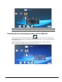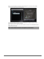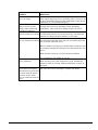
1
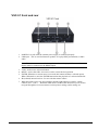
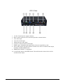
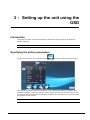
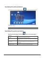
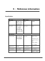
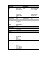
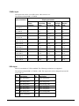
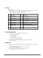
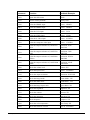
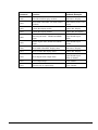
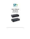
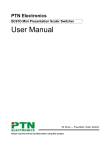
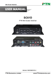
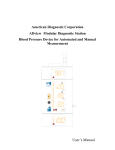
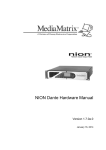
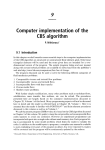
VSC-51 Quick Set-Up Guide Version 1.7.0a.1 February 6, 2014 Copyright notice The information contained in this manual is subject to change without notice. Peavey Electronics is not liable for improper installation or configuration. The information contained herein is intended only as an aid to qualified personnel in the design, installation and maintenance of engineered audio systems. The installing contractor or end user is ultimately responsible for the successful implementation of these systems. All creative content in this manual, including the layout, art design, content, photography, drawings, specifications and all other intellectual property is Copyright © 2014 Peavey Electronics Corporation. All Rights Reserved. Features & specifications subject to change without notice. The ratc-server component is based in part on the work of the libwebsockets project: http://libwebsockets.org. Prepared by Peavey Digital Research, 6 Elm Place, Eynsham, Oxford, OX29 4BD, UK. Email:[email protected]. Scope This guide describes how to configure a VSC-51 Mini Video Scaler with basic settings. ii Version 1.7.0a.1 February 6, 2014 1 - Important safety instructions Warning: When using electrical products, basic cautions should always be followed, including the following: 1. 2. 3. 4. 5. 6. 7. 8. 9. 10. 11. 12. 13. 14. 15. 16. 17. February 6, 2014 Read these instructions. Keep these instructions. Heed all warnings. Follow all instructions. Do not use this apparatus near water. Clean only with a dry cloth. Do not block any of the ventilation openings. Install in accordance with manufacturer’s instructions. Do not install near any heat sources such as radiators, heat registers, stoves or other apparatus (including amplifiers) that produce heat. Do not defeat the safety purpose of the polarized or grounding-type plug. A polarized plug has two blades with one wider than the other. A grounding type plug has two blades and a third grounding plug. The wide blade or third prong is provided for your safety. If the provided plug does not fit into your outlet, consult an electrician for replacement of the obsolete outlet. Protect the power cord from being walked on or pinched, particularly at plugs, convenience receptacles, and the point they exit from the apparatus. Only use attachments/accessories provided by the manufacturer. Use only with a cart, stand, tripod, bracket, or table specified by the manufacturer, or sold with the apparatus. When a cart is used, use caution when moving the cart/apparatus combination to avoid injury from tip-over. Unplug this apparatus during lightning storms or when unused for long periods of time. Refer all servicing to qualified service personnel. Servicing is required when the apparatus has been damaged in any way, such as power-supply cord or plug is damaged, liquid has been spilled or objects have fallen into the apparatus, the apparatus has been exposed to rain or moisture, does not operate normally, or has been dropped. Never break off the ground pin. Write for our free booklet Shock Hazard and Grounding. Connect only to a power supply of the type marked on the unit adjacent to the power supply cord. If this product is to be mounted in an equipment rack, rear support should be provided. Note for UK only: If the colors of the wires in the mains lead of this unit do not correspond with the terminals in your plug‚ proceed as follows: a) The wire that is colored green and yellow must be connected to the terminal that is marked by the letter E‚ the earth symbol‚ Version 1.7.0a.1 1 b) colored green or colored green and yellow. c) The wire that is colored blue must be connected to the terminal that is marked with the letter N or the color black. d) The wire that is colored brown must be connected to the terminal that is marked with the letter L or the color red. 18. This electrical apparatus should not be exposed to dripping or splashing and care should be taken not to place objects containing liquids, such as vases, upon the apparatus. 19. The on/off switch in this unit does not break both sides of the primary mains. Hazardous energy can be present inside the chassis when the on/off switch is in the off position. The mains plug or appliance coupler is used as the disconnect device, the disconnect device shall remain readily operable. 20. Exposure to extremely high noise levels may cause a permanent hearing loss. Individuals vary considerably in susceptibility to noise-induced hearing loss, but nearly everyone will lose some hearing if exposed to sufficiently intense noise for a sufficient time. The U.S. Government’s Occupational Safety and Health Administration (OSHA) has specified the following permissible noise level exposures: Duration Per Day in Hours Sound Level dBA, Slow Response 8 90 6 92 4 95 3 97 2 100 1½ 102 1 105 ½ 110 ¼ or less 115 According to OSHA, any exposure in excess of the above permissible limits could result in some hearing loss. Ear plugs or protectors to the ear canals or over the ears must be worn when operating this amplification system in order to prevent a permanent hearing loss, if exposure is in excess of the limits as set forth above. To ensure against potentially dangerous exposure to high sound pressure levels, it is recommended that all persons exposed to equipment capable of producing high sound pressure levels such as this amplification system be protected by hearing protectors while this unit is in operation. SAVE THESE INSTRUCTIONS! 2 Version 1.7.0a.1 February 6, 2014 2 - Introduction What is VSC-51? VSC-51 is a full HD video scaler switcher. The device scales and switches any HDMI, VGA, YPbPr, C-Video or S-video video signal to HDMI up to 1080P. It is controllable via buttons on the front, the IR sensor and the RS232 port. It has 6 video inputs and 5 audio inputs. Features 6 video Inputs: 2 x HDMI, 1 x VGA, 1 x YPbPr, 1 x C-video & 1 x S-video. Upscale to HDMI output at 1080P. 3 audio outputs: HDMI embedded audio, 3.5mm stereo audio and Coaxial (SPDIF). Selectable output resolutions. Adjustable display output H/V size to solve overscale problems. H/V adjustable display output position. Picture/MP3 display via USB (low-cost video player for a free-standing Kiosk). Powerful OSD function with full control; supports output freeze function. Presets of video parameters can be saved and selected from the on-screen display. Fast switching between source inputs eliminating visible transition. HDMI1.3 and HDCP compatible. Firmware upgradable via USB. Front panel lockout. Controllable via button, IR and RS232. What's in the box? VSC-51 products are packaged in a single container. This container includes the following items: 1x VSC-51 1 x Power adapter (DC 12V) 1 x IR remote (cell battery is not included) 1 x Captive screw connector 1 x user manual. If any of these items are missing, please contact your Authorized Peavey MediaMatrix contractor/dealer. February 6, 2014 Version 1.7.0a.1 3 VSC-51 front and rear 1. POWER: Lit (red) when the external power supply is connected properly. 2. USB input. This is used for firmware updates, or to play JPEG presentations, or MP3 audio. Note: These features are controlled using the On-Screen Display (OSD), so a video display must be connected to the HDMI output. 3. Video / audio source selection buttons. 4. MENU: Actives the OSD. Also can be used to cancel the last operation. 5. ENTER: When the on screen menu is accessed, this button confirms a selected option. When USB mode is used, the ENTER button starts the playback of a selected media file. 6. IR (infrared) internal receiver. For use with the remote control. 7. When the OSD is not in use, the left button and the right button are used for volume control (VOL-, VOL+). When the OSD mode is enabled, the direction keys are used to navigate through the on-screen menus to select picture settings, audio settings etc. 4 Version 1.7.0a.1 February 6, 2014 1. 2. 3. 4. 5. 6. 7. 8. 12V DC: External power supply connector. RS232: Serial connector for bi-directional pass-thru communications. VGA video input. VGA stereo audio input. YPbPr and stereo audio input. S-Video/C-Video and stereo audio input. HDMI output. Embedded with digital audio with level controlled by scaler. Stereo audio output. The audio from the selected video will be switched to this output, including embedded HDMI audio. 9. HDMI inputs. HDCP 1.3 is supported. 10. Coaxial audio output, with SPDIF format. The audio from the selected video will be switched to this output. February 6, 2014 Version 1.7.0a.1 5 Infrared remote control Source selection controls. Audio is automatically selected when video is selected. Special features not available using front panel. OSD and volume controls. Output resolution selection controls. Tip: The output resolution can be set using the OSD, RS-232 serial commands, or using the remote control. 6 Version 1.7.0a.1 February 6, 2014 3 - Setting up the unit using the OSD Introduction The product provides an On-Screen Display (OSD) menu with support for English and Chinese languages. Note: Many of the features are used only during initial installation and setup. Specifying the picture parameters The first icon from the left of the OSD menu is used to set the picture parameters. The settings include the picture mode presets, color temperature, contrast, brightness, hue, saturation, sharpness, scale, and Advance picture adjust. The Advance Picture Adjust is used to enable/disable the Digital Noise Reduction (DNR), Color Trend Increase (CTI), flesh tone and Adaptive Luma Control. Note: Not all parameters are available with all inputs. February 6, 2014 Version 1.7.0a.1 7 Specifying the audio parameters The second icon from the left of the OSD menu is used to set the audio parameters. The settings include sound effect presets, bass, treble, balance, scene mode, surround and smart volume setting. Note: Not all parameters are available with all inputs. Specifying the system parameters The third icon from the left of the OSD menu is used to set the system parameters. These include the OSD language, Listen, output image freeze, VGA setting and output adjustment. 8 Language Toggles between English and Chinese. Listen Audio output only. To resume video output, press the MENU button. VGA setting Adjust the H/V signal of VGA input, including auto adjustment. Output adjustment Adjust H/V size and H/V position of the output. Version 1.7.0a.1 February 6, 2014 Note: Not all parameters are available with all inputs. Viewing photos and playing audio via the USB port The fourth icon from the left of the OSD menu is used to browse the contents of a USB flash disk inserted into the USB port at the front of the VSC-51. You can play MP3 files and view JPG files. When displaying JPG images, you can set the presentation order (random, sequence or manual), and the presentation speed (fast, medium or slow). February 6, 2014 Version 1.7.0a.1 9 When you select USB, the screen below will be displayed. You can browse the available folders and select files from the USB flash disk. Use the arrow buttons to navigate, and the ENTER button to confirm a selection. Use the MENU button to return to the previous page. When using the remote control, press OK to confirm a selection. Use the RETURN button to return to the previous page. Note: A screen resolution of 1024x768 is not supported by the USB interface. 10 Version 1.7.0a.1 February 6, 2014 4 - Maintaining the unit Updating the firmware You can update the firmware on the VSC-51 using a flash disk inserted into the USB port at the front. MediaMatrix Technical Support (mailto:[email protected]) will provide you with the files you need to install on the flash drive and explain the procedure. To update the firmware 1. Copy the new firmware file to the main (root) directory of a USB flash disk. 2. Connect the VSC-51 to a video monitor via the HDMI output. 3. Plug the USB flash disk into the VSC-51 USB port. 4. Press and hold the MENU button for 15 seconds or until the update menu appears on the video monitor. The VSC-51 will automatically find and install the new firmware from USB flash disk. 5. After the update is finished, reboot and send the command 0617% to the RS-232 serial port to restore the unit to factory settings. 6. Reboot once again to finish the process. Tip: If sending the RS-232 command to restore factory settings is unsuccessful, change the output baud rate to 115200 and try again. Remember to return the unit to the normal serial communication settings: RS-232, baud rate: 9600, data bit: 8, stop bit: 1, parity: none. Troubleshooting Problem What to do No output image Check if there is any signal at the input. Check if there is any signal at the output. You can check these using an oscilloscope or a multimeter. Ghosting on image February 6, 2014 This is generally is not a faulty switch/scaler, but may be caused by poor quality cabling (to or from the switch/scaler), or incorrect setup on the display. Check cables and their connections, as well as the display setup. Version 1.7.0a.1 11 Problem What to do Waves on image If the output image has waves, especially if the waves move up or down, check that all devices and components (video players, computers, etc.) are grounded properly. Static or waves become stronger when connecting using RCA connectors Possibly due to incorrect grounding. Check grounding immediately. This could cause damage to the VSC device. Remote control not working Check that the batteries are inserted correctly. Check that the batteries are charged. Replace batteries as necessary. RS-232 control not working Check that the baud rate on the VSC device matches the baud rate set on the connected device. When a computer is being used, check that the COM port set on the computer matches the COM port set in the OSD on the VSC device. Make sure the serial port is in good working condition. Try swapping the TX and RX at one one. Power LED unlit Make sure the power cord connection is good, and that the adapter (if used) is working. Make sure that there is power at the outlet. Device does not respond The VSC device may need repair. Contact your dealer. when buttons are pressed on the front, when the remote control is used or when RS-232 communications are active. 12 Version 1.7.0a.1 February 6, 2014 5 - Reference information Specification Video input Video output Input 2 HDMI, 1 VGA, 1 YPbPr, 1 C-Video1 S-Video, 1 USB multimedia input Output 1 HDMI Video signal HDMI 1.3/DVI, Video signal VGA, RGBHV, RGBs, RGsB, RsBsGs, SECAM, PAL, NTSC 3.58, NTSC 4.42, MPEG /AVI /JPG for USB input HDMI 1080P,1920x1080; 720P, 1280x720; WXGA,1280x800; XGA, 1024x768. HDMI:4.95Gbps Video General Resolution range Bandwidth (1.65Gbps per color) C-Video/S-Video:150 MHz YPbPr: 170MHz VGA: 375MHz Maximum pixel clock 145MHz Video impedance 75Ω VGA cross talk -50dB@5MHz Input/output level 0.5V~2.0Vp-p Gain 0dB HDCP Compliant with DVI & HDMI 1.3 standards February 6, 2014 Version 1.7.0a.1 13 Audio input Audio output Input 3 Stereo Audio Output (RCA), 2 embedded HDMI audio stereo audio, S/PDIF COAX, and HDMI audio Input connector RCA for YPbPr, Output connector C-Video & S-Video audio, 3.5mm jack for VGA audio, HDMI for embedded audio 3.5mm jack for line audio, RCA for CO-AX audio (SPDIF), HDMI for embedded audio Input impedance >10kΩ Output impedance 50Ω Stereo channel separation >80dB @1KHz Audio general Frequency response CMRR 20Hz~20K Hz >90dB @20Hz to 20K Hz Control parts Control/Remote IR remote, Buttons & RS-232 serial General Communication protocol RS-232 Control Protocol Command type: ASCII Baud rate: 9600 Data bit: 8 Stop bit: 1 Parity bit: none 14 Temperature -20C ~ +45C Humidity 10% ~ 90% Power supply DC12V adapter Power consumption 7W Case dimension W 7 1/2” (195mm) with ears H 1 3/4” (44mm) D 4 3/8” (110mm) (wall mountable ) Product weight 0.4kg Version 1.7.0a.1 February 6, 2014 Supported video formats VSC-51 supports many types of video signals, including C-Video, S-Video, YPbPr, VGA and HDMI. All inputs are scaled to the selected HDMI format output. C-Video and S-Video input Supports PAL, SECAM and NTSC formats. From the OSD, the aspect ratio can be set to full-screen, wide screen or 4:3. . February 6, 2014 Version 1.7.0a.1 15 YPbPr input The aspect ratio can be set to full-screen, wide screen or 4:3. The maximum bandwidth is 170MHz. Input resolution Display parameter Frame mapping Scanning lines Frame Refresh frequency rate Hz Aspect ratio 720 x 480 I 2:1 525 15.75 60 4:3 720 x 480 P 1:1 525 31.5 60 4:3 720 x 576 I 2:1 625 15.625 50 4:3 720 x 576 P 1:1 625 31.25 50 4:3 1280 x 720 P 1:1 750 45 60 16:9 1280 x 720 P 1:1 750 37.50 50 16:9 1920×1080 I 2:1 1125 28.125 50 16:9 1920×1080 I 2:1 1125 33.75 60 16:9 1920×1080 I 2:1 1250 31.25 50 16:9 1920×1080 P 1:1 1250 62.5 50 16:9 1920×1080 P 1:1 1250 67.5 60 16:9 VGA input The VGA resolution is VESA standard. The following resolutions are supported. The maximum bandwidth is 375MHz (-3dB). The aspect ratio can be changed between full screen and 4:3. 16 No. Resolution No. Resolution 1 640×480@60Hz 8 1024×768@70Hz 2 640×480@72Hz 9 1024×768@75Hz 3 720×400@70Hz 10 1280×1024@75Hz 4 800×600@60Hz 11 1280×768@60Hz 5 800×600@72Hz 12 1360×768@60Hz 6 800×600@75Hz 13 1920×1080@60Hz 7 1024×768@60Hz Version 1.7.0a.1 February 6, 2014 HDMI input HDMI features: Digital embedded audio decoding, passing analog audio to the 3.5mm (1/8”) stereo output. Changeable aspect ratio (full-screen, wide screen, 4:3, auto-adjust). Support for HDCP1.3, compatible with DVI signal. No. Resolution No. Resolution 1 640×480@60Hz 9 1024×768@70Hz 2 640×480@72Hz 10 1024×768@75Hz 3 640×480@75Hz 11 1280×1024@75Hz 4 800×600@56Hz 12 1360×768@60Hz 5 800×600@60Hz 13 1920x540 6 800×600@72Hz 14 1920x1080I@(50Hz/60Hz) 7 800×600@75Hz 15 1920x1080P@(50Hz/60Hz/24Hz/30Hz) 8 1024×768@60Hz Audio input/output 3 Stereo audio inputs and 2 HDMI embedded audio inputs. 3 simultaneous audio outputs: 3.5mm stereo audio COAX (SPDIF) embedded audio to the HDMI output. Volume level adjustable from front panel. Volume, bass, and treble adjustable from OSD and RS-232 commands. Audio status presets. USB input February 6, 2014 Supports playback of JPG video files as a slideshow and MP3 audio files on a USB flash drive. Supports firmware updates. See Updating the firmware (on page 11). Can be configured using the OSD. The slideshow and MP3 audio can be played at the same time. USB provides a maximum of 5VDC, 500 mA. Version 1.7.0a.1 17 Communication protocols and command codes 18 Command Function Feedback Example 0600% MUTE Mute On 0601% Unmute Mute Off 0602% Audio level up Volume: XX 0603% Audio level down Volume: XX 0604% Lock the front panel buttons Panel Locked 0605% Unlock the front panel buttons Panel UnLocked 01XX% Preset the volume. The XX is ranging from 00 to 99 Volume: XX 02XX% Set brightness. The XX is ranging from 00 to Brightness: XX 99 03XX% Set contrast. The XX is ranging from 00 to 99 04XX% Set saturation. The XX is ranging from 00 to Saturation: XX 99 05XX% Set sharpness. The XX is ranging from 00 to Sharpness: XX 07 0606% Auto-adjust the input parameter(VGA only) VGA Adjustment 0607% Auto-adjust the color temperature Color Temp: XX 0608% ZOOM the image, set the aspect ratio Aspect Ratio: XX 0609% OK, for OSD selection OK 0610% Left arrow OSD Left 0611% Right arrow OSD Right 0612% Up arrow OSD Up 0613% Down arrow OSD Down 0614% Change (step through) picture mode Picture Mode : XX 0615% Change (step through) audio mode Sound Mode: XX Version 1.7.0a.1 Contrast: XX February 6, 2014 Command Function Feedback Example 0616% Opens the OSD menu. MENU 0617% Reset to factory defaults Factory reset 0620% Select the HDMI1 input Source: HDMI 1 0621% Select the HDMI2 input Source: HDMI 2 0622% Select the VGA input Source: VGA 0623% Select the YPbPr input Source: YPbPr 0624% Select the S-Video input Source: SVIDEO 0625% Select the composite video input Source: CVIDEO 0626% Select the output resolution of; 1024X768 XGA Resolution: XGA 1024X768 0627% Select the output resolution of; 1280X720 720P Resolution: 720P 1280X720 0628% Select the output resolution of; 1280X800 WXGA Resolution: WXGA 1280X800 0629% Select the output resolution of; 1920X1080 1080P Resolution: 1080P 1920X1080 0630% Check the volume level Volume: XX 0631% Check the input source Source: XXXXXX 0632% Check the output resolution Resolution: XXXXXX 0633% Check the image mode Picture Mode : XX 0634% Check the audio mode Sound Mode: XX 0635% Check the image aspect ratio Aspect Ratio: XX 0636% Check the brightness Brightness: XX 0637% Check the contrast Contrast: XX 0638% Check the saturation Saturation: XX 0639% Check sharpness Sharpness: XX 0640% Check the color temperature Color Temp: XX 0699% Check the firmware version VSC-51 V XXXXX February 6, 2014 Version 1.7.0a.1 19 20 Command Function Feedback Example 0644% OSD CHANNEL display enabled OSD Source: Display 0645% Shield OSD CHANNEL (all OSD features disabled) OSD Channel (Source):No Display 0646% Volume Bar display enable Volume Bar: Display 0647% Volume Bar display disable Volume Bar: No Display 0648% Enable digital audio(HDMI and SPDIF) output Digital Sound Ouput: Enable 0649% Disable digital audio (HDMI and SPDIF) output Digital Sound Ouput: Disable 0650% Check OSD CHANNEL display status OSD Source: Display 0651% Check Volume Bar display status Volume Bar: Display 0652% Check Digital audio output status Digital Sound Ouput: Enable or Disable 0655% Freeze output image Freeze: Enable 0656% Cancel freeze of output image Freeze: Disable Version 1.7.0a.1 February 6, 2014 Warranty statement MediaMatrix® PEAVEY ELECTRONICS CORPORATION DOMESTIC (USA) LIMITED WARRANTY Effective Date: May 1, 2005 What This Warranty Covers This Warranty covers defects in material and workmanship in Peavey MediaMatrix products purchased and serviced in the United States of America (USA). What This Warranty Does Not Cover The Warranty does not cover: (1) damage caused by accident, misuse, abuse, improper installation or operation, rental, product modification or neglect; (2) damage occurring during shipment; (3) damage caused by repair or service performed by persons not authorized by Peavey; (4) products on which the serial number has been altered, defaced or removed; (5) products not purchased from an Authorized MediaMatrix Integrator. This warranty does not cover associated costs incurred from servicing equipment, including, but not limited to, travel, jobsite-related costs, fabrication, freight, loaner equipment, installation, cabling or harnessing, mounting materials or other variable costs. Who This Warranty Protects In applications where the product is sold over the counter, this Warranty protects the original retail purchaser. In applications where the product is part of an integrated system, and such system is warrantied by the integrator as a complete assembly, this Warranty protects only the system integrator. How Long This Warranty Lasts The Warranty begins on the date of purchase by the original retail purchaser or on the date received by the system integrator. (See Who This Warranty Protects, above). The duration of the Warranty varies by product as summarized below. 5 Years MediaMatrix® DPU cards, NION™ Processing Nodes, CABs, I/O cards, Cinema Processors Power Amplifiers, Pre-Amplifiers, Mixers, Electronic Filter Sets and Dynamics Processors. 1 Year MM Series Cardframes, MF Series Cardframes, 90 Days Loudspeaker Components (including speakers, baskets, drivers, diaphragm replacement kits and passive filter networks.) and all Accessory Products What Peavey Will Do We will repair or replace (at Peavey's discretion) products covered by warranty at no charge for labor or materials. If the product or component must be shipped to Peavey for warranty service, the consumer must pay initial shipping costs. If the repairs are covered by warranty, Peavey will pay the return shipping costs. How To Get Warranty Service End Users: Take the defective product and your dated sales receipt or other proof of purchase to your Authorized MediaMatrix Systems Integrator or Authorized Peavey Service Center. System Integrators: Ship the defective product, prepaid, to Peavey Electronics Corporation, International Service Center, 412 Highway 11 & 80 East, Meridian, MS 39301, 601-483-5365. Include a detailed description of the problem, the name and location of the jobsite and a copy of your invoice as evidence of warranty coverage. Please include a complete return shipping address. Limitation of Implied Warranties ANY IMPLIED WARRANTIES, INCLUDING WARRANTIES OF MERCHANTABILITY AND FITNESS FOR A PARTICULAR PURPOSE, ARE LIMITED IN DURATION TO THE LENGTH OF THIS WARRANTY. Some states do not allow limitations on how long an implied warranty lasts, so the above limitation may not apply to you. Exclusions of Damages PEAVEY'S LIABILITY FOR ANY DEFECTIVE PRODUCT IS LIMITED TO THE REPAIR OR REPLACEMENT OF THE PRODUCT, AT PEAVEY'S OPTION. IF WE ELECT TO REPLACE THE PRODUCT, THE REPLACEMENT MAY BE A RECONDITIONED UNIT. PEAVEY SHALL NOT BE LIABLE FOR DAMAGES BASED ON INCONVENIENCE, LOSS OF USE, LOST PROFITS, LOST SAVINGS, DAMAGE TO ANY OTHER EQUIPMENT OR OTHER ITEMS AT THE SITE OF USE, OR ANY OTHER DAMAGES WHETHER INCIDENTAL, CONSEQUENTIAL OR OTHERWISE, EVEN IF PEAVEY HAS BEEN ADVISED OF THE POSSIBILITY OF SUCH DAMAGES. Some states do not allow the exclusion or limitation of incidental or consequential damages, so the above limitation or exclusion may not apply to you. This Warranty gives you specific legal rights, and you may also have other rights which vary from state to state. ControlMatrix™ Host Processors, Servers and Controllers, nControl, nTouch 180, nTouch 60, xControl LCDs, nWall, VCAT, VCAT-HD, VGA-2, VSC, Claro Remote Control Panels, Plates, Paging Stations, If you have any questions about this warranty or service received, or if you need assistance in locating an Authorized Service Center, please contact the Peavey International Service Center at (601) 483-5365. Features and specifications subject to change without notice. Ambient Sense Devices and other devices installed in user-accessible locations. February 6, 2014 Version 1.7.0a.1 21 MediaMatrix® A Division of Peavey Electronics Corp. 5022 Hartley Peavey Drive, Meridian Mississippi, 39305, USA Phone: 866.662.8750 http://mediamatrix.peavey.com Features & Specifications subject to change without notice Copyright © 2014, All Rights Reserved 80307514