1
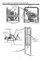
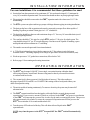
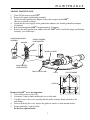
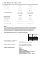
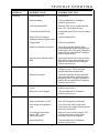
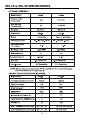
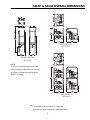
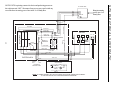
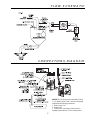
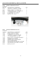
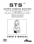
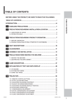
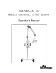
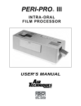
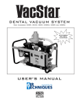
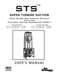
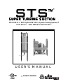
*
SUPER TURBINE SUCTION
54130 STS-15 TM WITH 20 GALLON CASTM (Cyclonic Action Separator)
54132 STS-30 TM WITH SINGLE 20 GALLON CASTM
USER’S MANUAL
* PATENTS PENDING
*
TABLE OF CONTENTS
Congratulations ........................................................................... 2
Warranty ...................................................................................... 3
Safety Instructions ....................................................................... 3
Key Parts Identification ................................................................ 4
Installation Information ............................................................... 5
Operating Information ................................................................. 5
Maintenance ................................................................................ 6,7
Site Requirements........................................................................ 8
Trouble Shooting ......................................................................... 9
Product Specification/Dimensions .............................................. 10
Overall Dimensions ..................................................................... 11
Electrical Schematic .................................................................... 12
Flow Schematic ........................................................................... 13
Connections Diagram .................................................................. 13
Accessories / Included ................................................................. 14
Accessories / Options .................................................................. 15
CONGRATULATIONS
Congratulations on the purchase of your new STSTM Dual Stage Dry Vacuum System (Super
Turbine Suction). The STSTM is a dry vacuum pump that produces high-volume air flow with
multiple users online. The STSTM is a medical dry vacuum pump which is designed for use in
a dental facility. The CASTM (Cyclonic Action Separator) tank will ensure that no liquids
or foams enter the vacuum pump. The relief valve is easily accessible on the CASTM. The
patented vacuum relief valve maintains a constant uniform vacuum. The powerful 3 phase
motor, with a highly reliable contactor and powerful transformer can be depended upon to start
every time. Your STSTM vacuum system and CASTM separator tank
are easily installed and maintained.
2
AIR TECHNIQUES WARRANTY
The STSTM and CASTM are warranted to be free from defects in material and workmanship from the date
of installation for a period of thirty-six (36) months.
Any item returned to our factory in Hicksville, New York through an Air Techniques' Authorized Dealer,
will be repaired or replaced at our option at no charge provided that our inspection shall indicate it to have
been defective. Dealer labor, shipping and handling charges are not covered by this warranty.
This warranty does not apply to damage due to shipping, misuse, careless handling or repairs by other
than authorized service personnel. Warranty void if installed or serviced by other than Authorized Air
Techniques' Dealer service personnel. Air Techniques, Inc. is not liable for indirect or consequential
damages or loss of any nature in connection with this equipment.
This warranty is in lieu of all other warranties expressed or implied. No representative or person is
authorized to assume for us any liability in connection with the sale of our equipment.
SAFETY INSTRUCTIONS
Use of the STSTM not in conformance with the instructions specified in this manual may
result in premature failure of the unit.
WARNING: To prevent fire or electrical shock, do not expose this appliance to rain or
moisture.
All user servicable items are described in the maintenance sections.
Manufacturing date code on serial number label is in format YYMM.
ATTENTION USERS:
This symbol alerts the user that
important Operating and
Maintenance instructions have been
included with the unit. Read carefully
to avoid any problems.
This symbol warns the user
that uninsulated voltage
within the unit may be of
sufficient magnitude to
cause electric shock.
I
This symbol indicates type B
equipment in accordance
with IEC 601-1
This symbol indicates the
presence of a hot surface or
component. Touching this
surface could result in bodily
injury.
ON
O OFF
MEDICAL ELECTRICAL EQUIPMENT
WITH RESPECT TO ELECTRICAL SHOCK, FIRE, MECHANICAL
AND OTHER SPECIFIED HAZARDS ONLY
IN ACCORDANCE WITH
UL-2601-1, CAN/CSA C22.2 NO.601.1
66CA
These symbols indicate the
“ON” and “OFF” position
for the power switch.
3
Protective Earth Ground.
KEY PARTS IDENTIFICATION
ELECTRICAL
BOX
ON/ OFF SWITCH WITH
CIRCUIT BREAKER
STS OUTLET
TO
CASTM
STS OUTLET
TO
CASTM
LEVELING FEET
SUCTION LINE
FROM OPERATORIES
WASH-OUT PORT
AND
VACUUM GAUGE
EXHAUST CONNECTION
SEPARATION
TANK COVER
3 CAPTIVE KNOBS
VACUUM
RELIEF VALVE
CAS OUTLET TO PUMP
CASTM (Cyclonic Action
Separator)
SEPARATION TANK
CHECK VALVE (for proper installation)
DRAIN
W/ CHECK VALVE
LEVELING FEET
4
INSTALLATION INFORMATION
For new installations it is recommended that these guidelines be used:
O
Suction line from the operatories to be a minimum of 2” dia. and must be sloped (1/4” minimum for
every 10’) toward the separation tank. The suction line should not have any sharp right angle bends.
O
The suction line should be connected to the CASTM separation tank with a short run of 1-1/2” dia.
flexible tubing.
O
The STSTM system can replace turbine type pumps with larger diameter piping in existing installations.
O
The drain on the base of the separation tank must be connected to an open floor drain capable of
handling 20 gallons per minute. Drain pipe size 1-1/2” schedule 40.
O
The drain line should be a short run with a minimum slope of ¼” for every 10’ toward the drain (avoid
any sharp right angle bends).
O
The vent line should be 3” dia. pipe for a single STSTM and two 3” dia. pipe for a dual system. The
vent should be sloped 1/4” per 10’ towards the pump. Vent line must be capable of handling vapors
and liquids and needs to terminate in a 2” end fitting.
O
The outside vent must be protected from rain and animals.
O
A 2” flexible air exhaust hose is provided to connect to the 3” dia. exhaust (vent) which must
terminate with a 2” end fitting at pump. Hose clamps are provided to secure hose to exhaust (vent).
O
Wash-out port uses a 3/4” garden hose connection, affixed to the CAS.
O
Refer to page 11 for mounting and securing instructions.
OPERATING INFORMATION
O
The STSTM may be turned “ON/OFF” from a single, convenient location within the dental
office using a Remote Control Panel. Remote wiring must be done by a licensed electrician in
accordance with local codes.
The vacuum level is factory preset at 10 in Hg (inches of mercury). This is the reading on
the gauge when all HVE’s and SE’s are CLOSED. If this setting needs to be adjusted contact your
dealer to readjust the setting.
O
O
The unit is capable of running continuously. To conserve electricity, the system may be turned off
when not in use.
O
The CASTM separation tank has been designed to collect the fluids evacuated during a normal
operating day. If an excessive amount of fluids are collected in the CASTM, the protective mechanism
in the CASTM will interrupt the vacuum flow in order for the tank to automatically drain. This process
takes approximately 60 seconds. To restore the vacuum to full operation turn OFF the power to the
STSTM for a minimum of 10 seconds and then back ON.
O
Turn the power OFF at the end of the day. This will drain collected liquids in the CASTM
separation tank.
NOTE: Any time the power to the STSTM is turned OFF the CASTM tank will automatically
drain.
5
MAINTENANCE
INITIAL MAINTENANCE
The CASTM uses patented technology to provide cyclonic action cleaning within the tank.
After installation, clean the vacuum lines with CleanStreamTM Cleaner. The STSTM system has the
capability of removing built up deposits in the piping system.
DAILY MAINTENANCE - CLEAN VACUUM LINES
To maintain the cleanliness of your CASTM, including all the vacuum lines and tubing in your
dental system, we recommend the daily use of CleanStreamTM Cleaner.
6
MAINTENANCE
YEARLY MAINTENANCE
1.
2.
3.
4.
5.
6.
Turn OFF the power to the STSTM.
Remove the gauge and bushing assembly.
Attach the male garden hose adapter to the wash-out port in the CASTM
(Be sure to include washers).
Attach the the water supply to the garden hose adapter (use female garden hose adapter
if required).
Run water through the CASTM for approximately 10 minutes.
Remove the male garden hose adapter from the CASTM and re-install the gauge and bushing
assembly. (use teflon tape)
GAUGE AND BUSHING
ASSEMBLY
WASHER
FEMALE GARDEN
HOSE ADAPTER
WASHER
WASH-OUT PORT
MALE GARDEN
HOSE ADAPTER
TANK COVER CLAMP
CASTM
CAPTIVE KNOBS
COVER
Removal of CASTM cover for inspection.
1. Turn off the power to the CAS.
2. Loosen the 3 captive knobs holding the cover to the tank.
3. Carefully remove the cover ensuring that the gasket remains firmly attached to the
tank flange.
4. Prior to replacing the cover, inspect the gasket to ensure a clean smooth surface.
5. Finger tighten the 3 captive knobs.
Do not over tighten knobs.
7
SITE REQUIREMENTS
ELECTRICAL
Minimum circuit breaker rating
Wire size AWG
Receptacle Type
SINGLE
30 A
#10
Hardwired
DUAL
Two 30A
2 each #10
Hardwired
SINGLE
DUAL
3” metal pipe
with 2” end fitting
3” (x 2) metal pipe
with 2” end fitting
SINGLE
DUAL
1/2”
1-1/2 to 2”
2 to 3”
1-1/2” FNPT
1/2”
2 to 3”
3 to 4”
1-1/2” FNPT
1-1/2” Schedule 40 Pipe
1-1/2” Schedule 40 Pipe
3/4” Garden Hose
3/4” Garden Hose
EXHAUST VENT PIPE
SUCTION LINE
Riser Diameter ID
Branch Line Dia. ID
Main Line Diameter
End Fitting
DRAIN LINE
WASH-OUT LINE
Note:
The STS unit must be used in a controlled temperature environment. Maintain equipment
room temperature between 40 and 105 degrees Fahrenheit. Adequate forced ventilation
must be provided across the unit by placing an appropriate exhaust fan oppositean
equivalent air intake vent. The fan should be higher that the associated intake vent.
Recommended minimum exhaust fan requirements are as follows:
STS-3
STS-5
STS-15
STS-6
STS-10
STS-30
ENVIRONMENTAL CONDITIONS
Transport and storage Temperature
500 CFM
600 CFM
800 CFM
1000 CFM
1200 CFM
1600 CFM
0° F to 150° F
Relative Humidity 90% no condensate
Operating Condition Temperature
40° F to 105° F with PVC vent pipe
Relative Humidity 90% no condensate
IEC601-1 CLASSIFICATION
Class 1
Type B
Transportable
Operation - Continuous
Equipment not suitable for use in the presence of
flammable anaesthetic mixture(s)
Protection against ingress of liquids. - Ordinary
8
TROUBLE SHOOTING
PROBLEM
POSSIBLE CAUSE
POSSIBLE SOLUTION
No suction
Pump not turned on.
Turn pump on.
Pump not running.
Call your authorized Air Techniques
dealer for repair service.
CAS separator tank full.
Shut unit “OFF” for 10 seconds then turn
back “ON”. Check drain for clog.
CAS hooked up backwards
Connect hose from STS to swivel tee fitting
on CAS.
Drain check valve clogged.
Techniques dealer for repair service
Call your authorized Air
Clogged drain.
Call your local plumber.
Kinked or collapsed suction hose.
Check the suction line from the unit to
the separation tank and the separation tank
to the opertory line. If clogged, collapsed or
kinked call your authorized Air Techniques
dealer for repair service.
Separator tank is full and will not
drain.
Tank must be hooked up to an open drain.
If hooked to an open drain and tank won't
drain call your authorized Air Techniques
dealer for repair service.
Restricted air exhaust.
Check air exhaust pipe to make sure it
conforms to specs. Check and clear
possible restrictions in exhaust line.
Restricted air suction.
Check the suction line from the unit to the
separation tank and the separation tank to
the opertory line. If clogged , collapsed or
kinked call your authorized Air Techniques
dealer for repair service.
Relief valve set high or stuck
closed.
Call your authorized Air Techniques
dealer for repair service.
Relief valve screen clogged.
Call your authorized Air Techniques
dealer for repair service.
Site circuit breaker is “OFF”.
Turn “ON” the site circuit breaker.
Pump circuit breaker is “OFF”.
Turn “ON” the pump circuit breaker.
Low voltage circuit breaker is
open.
If you can see the white section of the
circuit breaker, it is tripped. Flip this section
back in to reset breaker.
Low voltage remote switch
turned “OFF”, or not
connected properly.
Make sure remote switch is turned “ON”
or if not using remote, switch yellow
and orange wires twisted together.
Electrical problem.
Call your authorized Air Techniques
dealer for repair service.
.
Poor or low suction
Excessive suction
Pump does not run.
9
STS-15 & STS-30 SPECIFICATIONS
10
54130 & 54132 OVERALL DIMENSIONS
**
SINGLE STS-15
P/N 54110
20 GALLON CAS
P/N 54170
NOTE:
20 gallon CAS must be bolted to the wall
with brackets provided in the accessory kit.
20 gallon CAS cannot be stacked on top
of a STS-15 pump.
SINGLE STS-30
P/N 54630
**CAS heights can be increased by 8 inches and
decreased by 8 inches with chassis adjustment holes.
11
4x4 HANDY BOX
18 GA. YEL
10 GA. BLU
10 GA. BLK
10 GA. RED
W1
V1
U1
V2
U2
W2
4 3
ORN
BRN
ELECTRICAL BOX
24V
18 GA. BRN
18 GA. BLK
TRANSFORMER
L1
230V
L2
18 GA. ORN
L3
CIRCUIT
BREAKER
MOTOR
SWITCH/
CIRCUIT BREAKER
18 GA. YEL
18 GA. YEL
12
CONTACTOR
10 GA. BLU
10 GA. GRN/YEL
T1
10 GA. GRN/YEL
10 GA. BLK
10 GA. BLK
10 GA. RED
18 GA. RED
10 GA. RED
10 GA. BLU
18 GA. BLK
T3 T2
WIRE
NUT
18 GA. YEL
2 YEL
WIRE
NUT
TO REMOTE
CONTROL PANEL
Bring incomming
power into 4 x 4
Handy Box
BLK
RED
BLU
GRN/YEL
CONNECTION TO 24V
SWITCH ONLY
24VAC
YEL 2
BRN 4
ORN 3
NOTE: ALL REMOTE PANEL (24V SWITCH) WIRES SHOULD BE CONNECTED INTERNAL
TO THE ELECTRICAL BOX. USE PROVIDED STRAIN RELIEF.
43 44
STS ELECTRICAL SCHEMATIC
NOTE: If STS is spinning counter clockwise and producing pressure at
the outlet turn unit “OFF” disconnect from power source and switch any
two of the three incoming power lines in the 4 x 4 Handy Box.
FLOW SCHEMATIC
CONNECTIONS DIAGRAM
NOTE: The CAS accessory kit comes with 15 feet of
1-1/2” Black Flex PVC hose. Cut hose to the length
required for the following connections.
1. Suction line to CAS
2. Pump to CAS
3. CAS to Drain. If more than 15 feet of hose is
needed, please order P/N 57227 (order per foot).
13
ACCESSORIES/INCLUDED
54150
PUMP ACCESSORY PACK; STSTM
CONTENTS
PART NO.
DESCRIPTION OF COMPONENT
57253
ADAPTOR,1-1/2"MNPTX1-1/2"BARB
56057
HOSE,2 1/4"DIAX17"L,1"WIDE CUFF
89324
CLAMP;HOSE,1-9/16"- 2-1/2"MAX X 1/2"
57234
1-1/2",ELBOW,STREET 1-1/2” NPT
57169
CLAMP;HOSE, 1.31 - 2.25 DIA.
54105
MANUAL, STS 15 & 30
QTY
1
1
2
1
1
1
54135
TANK ACCESSORY PACK; CASTM
CONTENTS
PART NO. DESCRIPTION OF COMPONENT
57227
HOSE;1-1/2 DIA,PVC,BLACK
57169
CLAMP;HOSE, 1.31 - 2.25 DIA.
57253
ADAPTOR,1-1/2"MNPTX1-1/2"BARB
57234
1-1/2",ELBOW,STREET 1-1/2” NPT
31453
BOLT;1/4-20 X 1-3/4",HEX HEAD,GRADE 5
30610
WASHER;FLAT:1/4",PLATED
30222
WASHER;LOCK:1/4",SPLIT,PLATED
30049
NUT;1/4-20,HEX,PLATED
A1028
WALL BRACKET, RUGHT SIDE, CAS TANK
A1029
WALL BRACKET, LEFT SIDE, CAS TANK
30124
BOLT; LAG, 1/4 X 2”
QTY
15 FT
5
4
1
4
12
4
4
1
1
4
14
ACCESSORIES/OPTIONS
PART NO.
DESCRIPTION
54400
Installation Kit, Dual System
54061
Washout Connector Washer
54360
Installation Guide, STS and CAS
56200
Vacuum Equalizer
57660
CleanStream Starter Kit
57640
CleanStream Vacuum Cleaner (32 Packets)
15
Air Techniques is a leading manufacturer of dental equipment from air
compressors and vacuum systems to x-ray film processors, intraoral video
cameras, air abrasion and pro-grammable rapid curing light systems. We have
been manufacturing quality products for the dental professional since 1962.
T
T
T
T
T
T
T
T
T
T
T
AIRDENT II CSJ
AIRDENTJ II
ARC Light®
AIRSTAR®
VACSTARJ
PERI-PRO®
A/T 2000® XR
VISTACAM OMNI®
VISTACAM OMNI® ic4
STSJ
CASJ
CORPORATE HEADQUARTERS
70 Cantiague Rock Road, P.O. Box 870
Hicksville, NY 11802-0870
Telephone: (516) 433-7676 Fax: (516) 433-7684
1-800-AIR-TECH
www.airtechniques.com
WESTERN FACILITY
291 Bonnie Lane, Corona, CA 92880
Telephone: (909) 898-8555 Fax: (909) 898-7646
1-800-822-2899
P/N 54105 Rev. A