1
LIMIT 45O Wood Stove
Installation and Operating Instructions
Save These Instructions
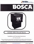
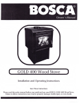
Please read this entire manual before you install and use your BOSCA LIMIT 450
Wood Stove.
Failure to follow instructions may result in property damage, bodily injury, or even death.
NorthlineExpress.com
www.NorthlineExpress.com
Toll-Free 1-866-667-8454
TABLE OF CONTENTS
SAFETY NOTICES
INTRODUCTION
3
INSTAI,I,ATION
The floor
Installation clearances
Chimney Connection
CHIMNFY
Factorv Built Chimnev
Masonry Chimney
Masonry Fireplace
Chimnev Heisht
Combustible Wall Chimnev Connector Pass - Throushs
MOBILE HOME INSTALLATION
10
OPERATING AND LIGHTING INSTRUCTIONS
11
Lishtins
11
Reloadins
L2
t2
MAINTFNAN(lF
Baffle
T2
Disposal of Ashes
13
Glass Reolacement
13
Glass Cleanine
13
Door Gasket Replacement
r4
Refractory Bricks Installing and Replacemenl
I4
Handle
Creosote - Formation and need for
removal
15
TROUBLESHOOTING
16
REPI,ACEMENT PARTS
16
LIFETIME LIMITED WARRANTY
19
NorthlineExpress.com
www.NorthlineExpress.com
Toll-Free 1-866-667-8454
.
SAFETY
NOTICF)
When your BOSCA LIMIT 450
is
not properly installed, a house fire may result. To reduce the risk of fire, follow the installation
instruclions. Contact local building, fire ofli'cials, or authority having jurisdiction about restrictions, permit and installation
inspection requirements in your area.
-
DO NOT USE CHEMICALS OR FLUIDS TO START THE FIRE.
DO NOT BURN GARBAGE OR FIAMMABIE FLUIDS SUCH
AS
GASOIINE, NAPHTHA OR ENGINE OIt.
HOT WHITE IN OPERATION. KEEP CHILDREN, CLOTHING AND
FURNITURE AWAY. CONTACT MAY CAUSE SKIN BURNS.
NEVER USE GASOLINE, GASOTINE-TYPETANTERN FUEL,
KEROSENE, CHARCOAT TIGHTER FLUID, ON SIMITAR TIQUIDS TO
START OF "FRESHEN UP" A FIRE IN THIS STOVE, KEEP ALL SUCH
TIQUIDS WELL AWAY FROM THE STOVE WHILE IT IS IN USE.
DO NOT ELEVATE FIRE, BUILD WOOD
FIRE DIRECTLY
ON FIREBOX
HEARTH.
BURN NATURAL WOOD ONIY. DO NOT BURN ANY OTHER
WOOD, ADEQUATETY AIR-DRIED.
AVOID BURNING GREEN WOOD.
FUELS. PREFER HIGH-QUAIITY
WOOD A SAFE DISTANCE FROM THE STOVE AND KEEP IT
OUT OF THE SPACE AROUND THE STOVE OR AREAS REQUIERED
FOR REFUETING AND ASH REMOVAI.
KEEP
THE BOSCA LTMIT 45O IS APPROVED FOR MOBILE HOME
INSTAIIATION. PTEASE FOttOW THIS MANUAT CAREFULLY
FOR ANY INSTAIIATION, INCLUDING IN A MOBITE HOME.
NorthlineExpress.com
www.NorthlineExpress.com
Toll-Free 1-866-667-8454
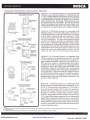
INTRODUCTION
We would like to congratulate you for selecting our BOSCA LIMIT 450. By purchasing a BOSCA product, you receive the
advantage of the strength, guaiantee and the more than 20 years gxperience BOSCA has in producing stoves and heaters
equippe"d with secondlry a-ir combustion system, which enable efficient consumption of the wood, as well as minimum
impact to the general environment.
Bosca Chile S.A. is the leading company in the production of wood stoves in Chile, with more than 250,000 stoves sold and
there are BOSCA products instialled in hiluses in Spain, Portugal, fugentina, Uruguay, Ecuador, and Mexico. In the production
of our stoves, we irse only the finest materials. Thlis, along w-ith the experiencebf the members of our staff, means for you a
product of high quality and dependability.
The BOSCA LIMIT 450 is a clean burning EPA certified, non-catalytic wood burning stove with 3,6 grams per hour particulate.
The BOSCA LIMIT 450 has been tested and listed by OMNI-Test Laboratories, Inc. The test standards are U11482 and ULC
s627.
Please read this entire manual before you install and use your BOSCA LIMIT 450. The purpose of this manual is to familiarize
you with your LIMIT 450's safe installhtion, operation and maintenance. It contains infbrmation that will be useful, so save it
for future reference.
INSTALLATION
For your ultimate safety and the proper function of your stove, it should be installed in accordance with the instructions of
this Manual.
The first step is to decide where is the most appropriate place to install your stove.
It is important to install the stove in an area with adequate air circulation and flow. This allows the warm air to more easily
^the
reach
intended rooms. Additionally, your stove's placement should enable, and not be an obstacle to free movement
people,
of
especially children.
Your stove and chimney connector must be far enough from combustible materials to meet all clearance requirements.
The floor
One of the main necessary precautions when installing a wood stove is to leave sufficient space between the stove (top, sides,
back, front, and under stove pipes) and any other material that can catch fire.
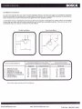
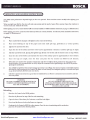
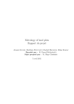
If the stove is to be installed on a combustible floor, it must be placed on an approved l/2" (13mm) non-co_mbustib_le hearth
pad with k = 0.84 BTU/in ft2 hr oF. In the USA, the floor proteitor m,u,st extenil 8" beyond ea.ch side of the flue loading.door
ind 16" to the front. In Canada, the floor protector mu sf extend 8" (200mm) beyond-each side and the back of the appliance
and 18" (450mm) to the front. (See fig. 1)
,/
8" (200 mm)
Canada
8" (200 mm
Canada
8" (200 mm)
Canada
8" - USA
r6'- usA
l8'(450m)
Canada
Fig.
NorthlineExpress.com
www.NorthlineExpress.com
1
Toll-Free 1-866-667-8454
' a rear vent installation the floor protection must also extend under the stovepipe a minimum
of 2" (50mm) beyond either
side of the pipe.
How to determine if alternate floor protection materials are acceptable.
All floor protection must be non-combustible (i.e.,.metals, briclq stone,
mineral
Si"i.T,'#i83,'!Xo"?:?'':$lf?;",[:J"ffi
filer boards, etc.). Any organic materials (i.e.,
ip"iineai"ii,,ol'
ro,"i
i,?,T,i#i'iJi,11".6tltgni[i{*X.kiru;;;i:"
'J-"
Procedure;
1.
Convert specification to R-value:
i. R-value given - no conversion needed.
ii.
k-factor is given with a required thickness (T) in inches:
n
iii. K-factor is given
with
a required thickness (T) in inches: n
=f
x
f
=n,.12
x
f
iv. r-factor is given with a required thickness (T) in inches:
R=rxT
2. Determine the R-value of the proposed arternate floor protector.
,,R".
i. Use the formula in step (1) to convert values not expressed
as
ii.
For multiple layers, add R-values of each layer to determine overall
R-value.
If the overall R-value of the system is greater than the R-value
of the specified floor protector, the altemate is acceptable.
Example; The specified fl-oor protector should b-e 3/4-inch thick material
with a k-factor of 0.g4. The proposed alternate is
4" brick with an i-factor of 0.2bver 1/8" mineraLb;d;iii,';i$;;;;
or0.29.
Step (a): Use formula above to convert specification to R_value.
R=
+"t=*nxo.T5
=0.8e3
Step (b); Calculate R of proposed svstem.
4" brick otr = d.2,fherefor6:
Rbricr=O.Zx4=0.431
1/8" mineral board of k = O.Zg, therefore
Rminerat
board
=
#g "
O.IZS =
0.43I
Rtotal = Rbri.k + Rmineral board = 0.8 + 0.431
ii";t
l:l;,1:f*:"rfltfsed
=
l.Z3l
system Rtotd of 1.231 tospecilied R or0.8e3. Since proposed
system &ota is greater than required,
Definitions
R
_
(ftz) (hr) ('F)
Btu
NorthlineExpress.com
,.
K=
(Bru) (in)
(ftz) (hr) fF)
_
^
(Btu) (ft)
(ft2) (hr) ("F)
www.NorthlineExpress.com
r:
(ftz) (hr) fF)
(Btu) (in)
=t
k
Toll-Free 1-866-667-8454
Installation Clearances
It is extremely important that you respect required installation distances and that you- respect localjnstallation regulations.
This is for youir safbty! The manlfacturer is not iesponsible for the product, if it is not installed folJowing these recommendations.
These clehrances may only be reduced by means approved by the regulatory authority.
A combustible surface is anl.thing that can burn (i.e. sheet rock, wall paper, wood, fabrics etc.) These surfaces are not limited
an"rl ahd include materials that are behind ndn-combustible materials. If you are not sure of the
combustible nature of a material, consult your local fire officials.
to those that are visible
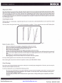
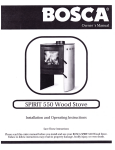
Corner Installation
Parallel Installation
CTEARANCE REQUIREMENTS:
A. SIDEWATL TO UNI1
B.- BACKWALLTO UNIT
C. CORNERWATL TO UNIT
D. SIDEWALL TO CONNECTOR
E.- BACKWALL TO CONNECTOR
F.- CORNERWALLTOCONNECTOR
G.. UNITTO CEILING
H.- FTOORTO CEILING
STANDARD RESIDENTIAL INSTALLATION
(SINGLEWATT & DOUBLEWALL CONNECTOR):
13"
20"
14"
22',
22,5
2l'
49"
84'
(330
(508
(356
(559
mm)
mm)
mm)
mm)
(572mm\
(533 mm)
(1.247 mm)
(2.134 mm)
7'
I I'
15.5'
16"
17"
18"
49"
84"
(178 mm)
(394 mm)
(279mm)
(406 mm)
(432 mm)
(457 mm)
(1.247mm)
(2.134 mm)
7"
11"
16"
t7'
18"
49'
84"
15,5'
(178 mm)
(394 mm)
(279 mm)
(406 mm)
(432 mm)
(457 mm)
(1.247mm)
(2.134 mm)
Note: Double wall is only allowed in US installations
NorthlineExpress.com
www.NorthlineExpress.com
Toll-Free 1-866-667-8454
'himney Connection
The chimney connector is a single walled pipe used to connect the stove -tg lhe chimney..For use with the appliance the
inirr""y .rirnector MUST be 6vin diamet'er, witn a minimum thickness of 24 gauge blatk steel or 26 gauge blued steel.
Aluminium and galvanized steel pipe is lot acceptqlle for use with the appliance. These materials cannot withstand the
extreme temperaTures of a wood fire and can give off toxic fumes when heated.
Do not use the connector pipe as a chimney.
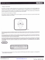
Each chimney connector or stovepipe section must be installed to the stove flue collar and to each other with the male
(crimped) enri toward the stove. See fig 2.
,oi*",H,,"J"^,
"i'no'*Too*
Fig.2
This prevents any amount of condensed or liquid creosote from running down the outside of the pipe or the stovetgp. All
jointi, including ihe flue collar connection musi be secured with three sheet metal screws to ensure that the sections do not
separate.
For the best performance the chimney c,onnector should be as short and direct as possible, with no more than two 90 elbows.
The maximum horizontal run is 36" and a recommended total length of stovepif e should not exceed 10 feet. Always slope
horizontal runs upward 1/a" Per foot toward the chimney.
No part of the chimney connector may pass through an attic or roof space, closet-or other concealed space, or through a
flooi ceiling. Allsections"of the chimney"connectors frust be accessible fo_t Sl_u_gu"_g.Whe^rg_p_qrygg9l1t9rgh.9 wallorpartition
of combuitble construction is desired, the installation must conform with NFPA fll or CAN/CSA-8365, ahd is also addressed
in this manual.
CHIMNEY
DO NOT CONNECT THIS UNIT TO A CHIMNEY
FLUE SERVING ANOTHER APPLIANCE. DO NOT
CONNECT TO ANY AIR DISTRIBUTION DUCT OR
SYSTEM.
{his
room heater must be connected to a 6" factory built UL 103 HT chimney (UtC 5629, in Canada) or a code-approved
,asonry chimney with a flue liner.
NorthlineExpress.com
www.NorthlineExpress.com
Toll-Free 1-866-667-8454
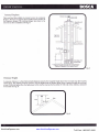
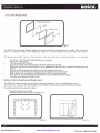
Factory Built Chimney
When a metal prefabricated chimney is used, BOSCA's
Adjustable roof
installation inslructjons must be followed. You must also purchase
(from BOSCA or its authorized retailer) and installth^e ceiling
support package or wallpass-tlrrough and "T" section package
firestops (where needed), insulation sllield, roof flashing, chimney
cap, etc. Maintain proper clearance to the structure
as
recommended by BOSCA. The chimney must be the required
height above the.ioof-or other obstructiohs for safety and pioper
draft operation. (See fig. 3)
Sunoort Box
wifh'built - in
starter section
One story house installation with attjc
Chimney is supported by celling
Fig. 3
Masonry Chimney
Adjustable roof
Ensure that a masonry chimney meets the minimum standards
of the National Fire Piotection Association (NFPA) by having it
inspected by a professional. Make sure there are ho
Flashing
crac-ks,
loose mortar or other signs of deterioration and blockage. Have
t!9 chimney cleaned before the stove is installed and operated.
When conirecting the stove through a combustible wall to a
masonry_chimney, special methods are needed (See fig. 4).
Refer to Combustible Wall Chimney Connector Pass-Throughs
on page 9.
Wall Strap
Wall Thimble
Chimney through outer wall with enclosed chase
Chimney is supported by tee support bracket
NorthlineExpress.com
www.NorthlineExpress.com
Toll-Free 1-866-667-8454
lasonry Fireplace
There are listed kits available to connect a stove to a masonry
fireplace. The kit is an adapter that is installed at the location of
the fireplace damper. The existing damper may have to be
removed to allow installation. (See fig. 5)
Chimney through outer wall with enclosed chase
Chimirey is sripported by tee support brackel
Fig.5
Chimney Height
A masonry chimney or a listed factory-build chimney must be the qeqrlire-d height above the roof and any other nearby
obstructioirs. The chimney must be ai least 3' (90 cni) higher than the highest pbint where it passes through the roof and
at least 2' (60 cm) higher than the highest part of the rooFor structure that is within 10' (305 cm) of the chimney, measured
horizontally (See fig. 6).
NorthlineExpress.com
www.NorthlineExpress.com
Toll-Free 1-866-667-8454
Combustible Wall Chimney Connector Pass - Throughs
Minimum chimenev clearance lo brick
and combustibles Zin. (50.8 mm)
Method A.12" (304.8 mm) Clearance to Combustible Wall
Member: Using a minimum thickness 3.5" (89 mm) brick and
a 5/8" (15.9 mm) minimum wall thickness clay liner, construct
a wall passthrough. The cla.y liner must confor;n to ASTM C315
(Standard Specification for Clay Fire Linings) or its equivalent.
Keep a minimum of 12" (304.8 mm) of brick masonry between
rlll
the clay liner and wall combustibles. The clay liner shallrun
F-r--r---1
l}#
tffil
lffi
_iF+..,r_.+l
from the brick masonry outer surface to the inner surface of the
chimney flue liner buinot past the inner surface. Firmly grout
G
o
or cement the clay liner in place to the chimney flue liner.
.E
Q
Method B. 9" (228.6 mm) Clearance to Combustible Wall
Member: Using a 6" (152.4 mm) inside diameter,listed, factory-
Minimum 12 in. {304.8 mm)
to combustibles
built Solid-Pak chimney section with insulation of
Minimum clearance
9 in. (228.6 mm)
Chimnev
Conneclor
o
Use chimnev
mlrs.-parts trj
attach connector
l"
(25.4 mm)
or more, build a wallpass-through with a minimum 9" (228.6
mm) air space between the outer wall of the chimney length
and wall combustibles. Use sheet metal supports fastened
securely to wall surfaces on all sides, to maintain the 9" (228.6
mm) air space. When fastening supports to chimney length,
do not penetrate the chimney liner (the inside wall of the SolidPak chimney). The inner end of the Solid Pak chimney section
shall be flush with the inside of the masonry chimney flue, and
sealed with a non-water soluble refractory cement. Use this
cement to also seal to the brick masonry penetration.
securely
E
E
\ \
r
$asonry
UnlmneY Sheet steel
Method C.6" (152.4 mm) Clearance to Combustible Wall
Member: Starting with a minimum 24 gage (.024" [.61 mm])
6" (152.4 mm) metalchimney connector, and a minimum24
suppofts
Minimum chimenev clearance t'o
sheet steel suo'Dorts and
combustibles 2 in'. (50.8 mm)
Two air channels
each lin. {25.4mm}
Chimnev
connecl6r
gage ventilated wall thimble which has two air channels of 1"
(25.4 mm) each, construct a wallpass-through. There shall be
a minimum 6" (152.4) mm separation area containing fiberglass
insulation, from the outer surface of the wall thimble to wall
combustibles. Support the wall thimble, and cover its opening
with a Z4-gage minimum sheet metalsupport. Maintain the 6"
(f 52.4 mm) space. There should also be a support sized to fit
and hold the metal chimney connector. See that the supports
are fastened securely to wall surfaces on all sides. Make sure
fasteners used to secure the metal chimney connector do not
penetrate chimney flue liner.
Method D. 2" (50.8 mm) Clearance to Combustible Wall
Member:
Sheet steel
Minimum clearance
1 in. (25.4 mm)
supports
Chimnev
Chimnev
connecl6r
-
Air Soace
2 in. (5d.8 mm)
Masonrv
Chimney
Start with a solid-pak listed factory built chimney section
at least I2" (3O4 mm) long, with insulation of 1" (25.4 mm) or
more, and an inside diameter of 8" (2 inches [51 mm] larger
than the 6" 1152.4 mml chimney connector). Use this as a passthrough for a minimum Z|-gage single wall steel chimney
connector. Keep solid-pak section concentric with and spaced
l" (25.4 mm) offthe chimney connector by way of sheet metal
support plates at both ends of chimney section. Cover opening
with and support chimney section on both sides with 24 gage
minimum sheet metal supports. See that the supports are fastened
securely to wall surfaces on all sides. Make sure fasteners used
to secure chimney flue liner.
NOTES:
L Connectors to a masonry chimney, excepting method B, shall extend in one conlinuous section through the wall pass,through system and the chimney wall, to but not past
the inner flue liner face.
2. A chimney connector shall not pass through an attic or roof space, closet or similar concealed space, or a floor, or ceiling.
NorthlineExpress.com
www.NorthlineExpress.com
Toll-Free 1-866-667-8454
MOBILE HOME INSTALLATION
For use only in USA (not allowed in Canada).
Follow these special requirements for installing your stove in a
mobile home:
-
An outside air inlet must be provided for combustion and must
remain clear of leaves, debiis ice and/or snow. It must be
unrestricted while unit is in use to prevent room air starvation
which can cause smoke spillage andhn inability to maintain a fire.
Smoke spillage can also set off smoke alarms.
- Outside air inlet installation: Use a BOSCA connector (see
Reolacement Parts. ps. 16) which You can purchase from an
oflicial BOSCA deal'ef a 4" single i,,rall aluniinum flex pipe of
appropriate length for installation, a rain cap and two 4" clamps,
ui,iiluUt" at youilocal hardware retailer.
To install the outside air inlet, place the connector over through
the hole behind Lhe heater, cbnnect the flex pipe and attach it
securely with one of the two clamps. The other side of the flex
pipe should be connected on the outside to the rain cap.
-
Permanentlv atlach the stove to your mobile home's floor. The
pedestal must"be bolted to the flo<jr. Use 7a" holes in the base to
bolt down the stove.
-
Regulation requires that unit must be grounded. Attach a piece
f # o8 cooper wire, at least 18" in length from the stove to the
,rassis of the mobile home.
- Stove must be installed with an approved Ut103 HT ventilated
chimney connector, Ut103 HT chimney and terminal cap with
spark airestor. Never use a single wall connector in a mobile
home installation.
- See clearances to combustibles on page 5 of this Manual or in
the Serial Number Label on the back of the stove.
- Follow the floor protections requirements detailed o n page 3.
- In Canada, this stove must be connected to a 6" factory-built
chimney conforming to CAN/ULC-629M.
- Use slicone to create an effective vapor barrier at the location
where the chimney or other componenti penetrates to the exterior
of the structure.
- Follow the chimnev and chimney connector manufacturer's
instructions when inslalling the flu-e system for use in mobile
homes.
-
Burn wood only. Other fuels may generate poisonous gases.
Chimney must be removed when transporting mobile home'
CAUTION:
WARNING:
DO NOT INSTALL IN SLEEPING ROOM
NorthlineExpress.com
THE STRUCTURAL INTEGRITY OF THE MOBILE
HOME FLOOR, WALL AND CEILING/ROOF MUST
www.NorthlineExpress.com
BE MAINTAINED.
Toll-Free 1-866-667-8454
OPERATING AND LIGHTING INSTRUCTIONS
Your LIMIT 450's performance depends largely on how it is operated. Please read this section carefully before lighting your
first fire.
When you light your first fire, the stove will emit some smoke and the smell
vent the room and eliminate the smell .
of
paint. This is normal. Open the windows to
Before lighting your stove, ensure that the baffle is conectly installed. For bafile installation instructions, se page 12 (Maintenance).
Before lighting your stove, ensure that the refractory bricks are conectly installed. For refractory bricks installation inshuctions,
see page l4 fMaintenance).
Lighting
n
!
!
I
I
U
!
!
Phce crushed sheets of paper or firelighters in the center of the firebox.
Place some kindling on top
of the paper and some small split logs, preferably in a vertical position.
tight the fire and close the door.
Open the door of the ashtray and leave it this way for approximately 3 minutes or until the split logs are alight.
Add the load of firewood, placing the lightest logs directly over the fire and the heavier ones on top of these.
Close the door of the firebox and maintain the door of the ashtray open for approximately 5 more minutes.
Once the logs are alight, close the door and place the Air Control on HIGH for 20 minutes.
When the stove reaches the operation temperature and there is suflicient draft, graduate the Air Control to the
desired position. It is recommendable to slowly adjust this command before graduating to the MEDIUM position
(prolonged combustion).
!
You will find by experience how to best manage your stove to your liking. You must not expect an immediate reaction
from the fire when moving the Air Control. The flame willnot intensify nor extinguish quickly as it would with liquid
or gas fuels. Solid fuels, like firewood, react slowly.
!
If the fire is initiated as instructed, a good base is established for an effective combustion that is smokeless and that
does not pollute.
WARNING
DO NOT OVERFIRE.IF THE STOVETOP OR
CHIMNEY CONNECTOR PIPE GLOW RED,
YOU ARE OVERFIRING.
IMPORTANT
DO NOT OPERATE THE STOVE FOR
PROLONGED PERIODS WITH THE DOOR OF
THE ASHTRAY OPEN. DO SO ONLY UNTIL THE
WOOD LOAD IS ALIGHT.
Reloading
!
Place the Air Controlin the HIGH position.
I
U
I
!
Place the dry firewood on top of the live coals remaining.
Open the door of the ashtray for 5 minutes or until the load alights.
Never load the firewood when the flames are vigorous.
Graduate the Air Conhol to HIGH for a few minutes. Once the stove
place the Air Control in the desired position.
NorthlineExpress.com
is
maintaining stable combustion,
www.NorthlineExpress.com
Toll-Free 1-866-667-8454
To obtain good combustion during the whole night, proceed as follows:
I
u
I
Form a base of live coals at the bottom of the firebox.
load the stove completely with dry firewood.
When flames begin to appear on the logs move the
Air Control to MEDIUM.
How do Iload my stove after a prolonged combustion?
!
!
!
!
At the end of a long combustion cycle, reestablish the fire adding a few small split logs and small
logs.
Open the door of the ashtray for 5 minutes or until the split logs and small logs are alight.
logs.
Ailow the temperature of the stove to recuperate before adding larger
Reload the stove according to the description above.
MAINTENANCE
The LIMIT 450 requires little maintenance. However, there are parts of you stove that should be checked periodically,
depending on the stove's use.
Baffle
Your LIMIT 450 stove has a removeable baffle that needs to be replaced periodically, depending on the stove's use.
When the baffle needs to be removed, make sure that the stove is cold before putting your hands into the firebox.
To replace the baffle, you have to dismantle the rear panel of your stove (fig.7):
1)
;
3)
Remove the rear panel, pulling it towards you.
4)
Once the bolts are loose, slide the baffle down as indicated in figure 8. Care
to make sure it doesn't accidentally fall, as this may result in serious injury (fig.
5)
To place the new baffle in its proper position, insert it into the firebox,
in such a way that it rests on the support brackets installed specially for
the baffle. Make sure that the baffle air pipe is inserted completely into
Release the 4 bolts located on the sides of the rear panel, using a 1Omm wrench.
Release the bolts that fix the baffle to the firebox, using a 10mm wrench.
,
angle the baffle on one side
the hole in the back of the firebox (Fig 10) and the bolts have gone
through the holes to the outside of the fixebox.
6)
Bolt the baffle to the rear wall of the firebox from the outside.
7)
Place the rear panel back in place, be sure that it is correctly set and
bolt it.
ig.7
Fig.8
NorthlineExpress.com
www.NorthlineExpress.com
Toll-Free 1-866-667-8454
Disposal of Ashes
Your unit's firebox has a grooved base, through which the ashes from the wood bumed automatically deposit into the ashbin.
When the ashbin is full, make sure that the stove and the ashes are cold (remember that the coals can remain hot for up to
36 hours) and place the ashes in a metal container with a tight fitting lid. The closed.container of ashes should be placed
on a noncombustible floor or on the ground, well away from all combustible materials, pending final disposal. If the ashes
are disposed of by burial in soil or otherwise locally dispersed they should be retained in the closed container until all cinders
have thoroughly cooled.
Glass Replacements
The front glass is a ceramic glass, especially made for use in wood stoves, and should therefore not be marred by normal
use of the stove.
If for any reason the glass does break, it will be necessary to replace it. Never operate your stove with broken glass.
Fig. 1l
Replace the glass as follows:
Make sure that the fire is completely extinguished and the stove is cold.
Protect your hands with gloves that are appropriate for this type of work.
Remove the hont door, chrefully pushing it upward (fig I l).
Place the door on a flat surface.
Unscrew the bolts that hold down the stainless-steel frame on the stove door.
Separate the door frame from the glass. The glass should be loose on the door, once the frame has been removed.
Pla'ce a new sheet of glass on the iioor, reset the frame in its original position, then screw the frame in place on the
-
door.
Reinstall the door, inserting the bottom part first, then the top part.
Before lighting a new fire, ensure that the door is seated in its correct position.
Use only ceramic glass for use in wood stoves. Do not use other type of glass.
If the ceramic glass of your stove needs to be replaced, contact your Official BOSCA Dealer.
Glass Cleaning
One of the more attractive features of your stove is that you can actually enjoy seeing the fire. However, your view may be
obscured when the glass becomes dirty.
In order to minimize this, we recommend the following advice:
-
The main cause of dirt spots on your glass is directly connected with the humidity content of the wood used, along
with maintaining the Aii Control setting on "Low" Position. Use only dry wood. Store it adequately, and keep the
Air Controlat the "Medium" position.
Clean the glass periodically riitfr a commercialstove glass cleaner, waiting untilthe glass is completely cold before
cleaning.
NorthlineExpress.com
www.NorthlineExpress.com
Toll-Free 1-866-667-8454
/oor Gasket Replacement
STAINLESS STEEL FRAME
ftgL2.
Your LIMIT 450 uses rope-type fiberglass gaskets at the interior of the front and ashtray doors to sealed it. After a time of use,
gaskets can become brittle and compressed, begin
to lose their effectiveness and need to be
replace.
To replace any gasket, be sure that the fire is out and the stove is cold and follow as is describe:
-
Use Fil-Tec ru MD .500 G Black Fiberglass Rope or equivalent.
Remove the existing gasket.
Clean the stainless steel channel.
Measure the length of the rope by laying it out in the stainless steel channel.
Remove the rope from the channeland cut it to the appropriate length. Take care to ensure that the rope does not
-
Place a bead of high-temperature adhesive in the clean stainless-steel channel.
Beginning at one of the ends, press the gasket into the stainless-steel channel interior.
Before cutting, make sure the rope ends properly meet. Do not overlap rope ends.
Firmly press the rope en make sure it properly seats into the stainless-steel channel interior.
Clean any excess adhesive and allow to dry.
unravel.
Refractory Bricks Installing and Replacement
Your LIMIT 450's firebox interior is covered with 18 refractory brick (figure 13 a.). To avoid damages in your
during the transport , the refractory brick are not Installed and are stored in a box inside your stove firebox.
stove
To install the refractory bricks, proceed as follow:
-
Use gloves to protect your hands
Installthe refractory bricks as shown in figure 13 b.
\
\{
(:i.
\
..,,?
..?
,r./
------------->l
fig.13 a.
NorthlineExpress.com
www.NorthlineExpress.com
fig. 13 b.
Toll-Free 1-866-667-8454
S-ome bricks may brake due to the normal use of the appliance or from impact when loading wood.
If this occurs, proceed as follows, after making sure that any fire is extinguished and the appliance and brick are cold:
-
Use gloves to protect your hands
Clean any ashes from the firebox
Take hold of the brick to be replaced, and push it upwards. This should leave you enough space to move the bottom
-
Clean any pieces of brick remaining in the space where the new brick will be placed
To insert the new brick, place the upper end in the molding in the top part of the fnebox
Once the upper part of the brick is well seated, push it towards the inside surface of the firebox, until the brick is
completely seated in place.
of the brick toward the center of the firebox
If you need to replace Refractory Bricks, check
with your Official BOSCA Dealer.
Handle
After some use, it may be necessary to replace the wood part of the front door handle.
[Y
,
STEEL
HANDLE
\)
e\
,*..DHANDLE
\\
\u(V/to.*ur
HEAD cuP scREW
Replace the wooden handle as follows:
-
Be sure that the fire is out and the stove is cold
Remove the existing wood handle (use a N"4 Allan key)
Turn the screw as far as possible and remove
To replace the wood handle, check with your Official BOSCA Dealer.
Creosote - Formation and need for removal
When wood is burned slowly, it produces tar and other organic vapors, which combine with expelled moisture to form
creosote. The creosote vapors condense in the relatively cool chimney flue of a slow burning fire. As a result, creosote residue
accumulates on the flue lining. When ignited this creosote makes an extremely hot fire.
The chimney connector and chimney should be inspected at least every two months during the heating season to determine
if creosote build up has occurred.
If creosote has accumulated it should be removed to reduce the risk of a chimney fire.
NorthlineExpress.com
www.NorthlineExpress.com
Toll-Free 1-866-667-8454
-t-m
Your LIMIT 450 will operate with few problems, and most of those will occur due to inconect operation, poor-quality wood,
improper installation, or failure to clean the flue piping.
-
The following lists solutions to the most common problems in the operation of the IIMIT 450:
Solution
-Use seasoned wood
-Reload your stove when it has a good bed of embers
- Set
the Air Controlin "M6dium" or "High" position.
-Use seasoned wood
normal for your stove to emit smoke during the first
few minutes of operation. The smoke will dissipate when
the firebox reaches the normal operating temperature..
- It is
- Use seasoned wood
- Keep the Air Controlat "Medium" or "High" position
- Make sure that the gasket is in good condition.
-
If your heater is more
lhanZ years old, replace the baffle.-
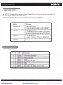
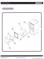
REPLACEMENT PARTS
Code
No
127znnR?
2
12720079
3
r03t0274
4
r0320L27
12720074
5
6
7
NorthlineExpress.com
t2720056
t2720075
Description
Door (without ceramic glass)
Ceramic Glass (with easket)
Rehactorv tsricks (set)
AShDAN
Ashpan Door (with rope)
Wood Handle Assemblv
Batlle
8
q
10310320
Outside Air Connector
12.720077
Glass Retainer (with brackets. screws and rooe)
10
r2720076
Owner's Manual
www.NorthlineExpress.com
Toll-Free 1-866-667-8454
REPLACEMENT PARTS
NorthlineExpress.com
www.NorthlineExpress.com
Toll-Free 1-866-667-8454
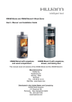
DO NOT REMOVE THIS LABEL / NE PAS ENLEVER CETTE ETIQUETTE
BOSCf,
CONTACT LOCAL BUILDING OR FIRE OFFICIALS ABOUT INSTALLATION AND RESTRICTIONS IN YOURAREA. / REINSEIGNEZ.
VOUS AUPRES OES AUTORITES LOCALES DE LA CONSTRUCTION ET DE LA PREVENTION DES INCENDIES AU SUJET DES
RESTRICTIONS ET INSPECTIONS D1NSTALLATION DANS VOTRE REGION.
Otrfll d L.boralond.
lnc.
LISTED SOLID FUEL BURNING APPLIANCE SUITABLE FOR USE IN RESIDENTIAL INSTALLATIONS. /APPAREIL DE CHAUFFAGE A
COMBUSTIBLES SOLIOES HOi'OLOGUE POUR INSTALLATIONS RESIDENNELLES.
LIMIT 450
MoDEL/ MoDELE,
Serial Number
Numero de Serie
- lnstall and use only in accordence with the manufacturer's
installation and operating instructions. Contact your local building or fire officials
about restrictions and installation inspection in your area. Refer to local building
codes and manufacturer's instructions for precautions required for passing a
chimney trough a combustible wall ceiling. Do not run a chimney connector
trough a combustible wall ceiling. Do not connect this unit to a chimney flue
serving another appliance. Clearances may be reduced by methods specified in
NFPA 211, listed wall shields, pipe shields, or other means approved by local
building or fire officials.
batiment. Ne pas lai16 piasser le tuyau de chemmin6e directament i travers une surface combustible.
Ne pas conndc{er cet'aopareil li chemin6e d'un autre aDDareil. Les d6oaoements minimaux des
mat'6riaux combustiblesbeuvent etre reduits selons les mdthodes sD6cifi6e; dans NFPA 211. avec des
protections murales hodrologu6es, des protections de chimen6e hbmologu6es, ou d'autres moyens
i
approuves par les autorit€s de la construction et de la pr6vention des incendies.
Pour usage uniquement avec du bois.
For use with solid wood fuel only (cord wood).
Faites fonctionner l'appareil avec les portes de chargement ferm6es - ouwir uniquement pour charger.
operated with feed door closed . open to feed fire only.
Ne pas utiliser une grille suppl6mentaire pour 6lever le feu . faites le feu directement sur le foyer.
Do not use a grate to elevate fire - build fire directly on hearth.
Ne pas faire fonctonnier l'aappareil avec la porte cendrier ouverte.
Do not operate with the ash door open.
DO NOT OVERFIRE
PREVENTION DES INCENDIES: lnstallez et utilisez conform6ment aux instructions du fabricant.
Renseignez.vuos auprds des autoritds locales de la construction et de la pr6vention des incendies au
sujet de restrictions et inspections d'installation dans votre 169ion. Des m6thodes sp6ciales sont
requises lors du percaqe d'un mur ou plafond. V6rifier les instruttions du fabricant et les codes du
. lf heater or chimney connectors glows, you
NE PAS SURCHAUFFER - Si une panie de I'appareil ou du reccordement de chemin6e commence d
rougeoyer, vous etes en situation de surchauffe.
are overfiring.
lnspec{er 6t nettoyer la chemin6e fr6quentmment; dans certaines conditions de fonctionnemment (par
exemple, mise au ralenti sans afteridre la combustions des volatiles) une formation de cr6osbte
goudron puet se produire rapidement.
lnspect and clean chimney frequently . under certain condictions of use, creosote
buildup may occur rapidly.
FREESTANDING / INSTALLAT ION
lor use with solid fuels or masonry chimney. / pour les installations residentielles:
MSG vers une chemin6E pr6fabriqu6e homoloquoe (type UL103 HT ou ULC 5629) ou
tiliser un connecteur de chemin6e de 6" de diamitre, en acier noir de
)rs une chemin6e maconn6e.
CLEARANCE REQUIREMENTS:
DEGAGEMENTS MTNTMAUx DEs ilATERTAUX coMBUSTTBLES:
STANDARO RESIDENTIAL INSTALLATION
(SINGLEWALL & DOUBLEWALL CONNECTOR):
INSTALLATION RESIDENTIELLE STANDARD
(TUyAU DE RAccoRDEMENT A srMpLE pARor er A DoueLe
STDEWALL
To uNrr I DU MUR DE coTE AU poELE
BACKWALL TO UNIT I DU MUR ARRIERE AU POELE
coRNERWALL To uNrr I DU MUR ou cotN AU poELE
SIOEWALT TO CONNECTOR I DU MUR DE COTE AU RECCORD OE CHEMINEE
F..
BAcKWALL To coNNEcToR / DU MUR ARRTERE AU REccoRD DE cHEMTNEE
CORNERWALL TO CoNNECTOR I DU MUR DE COIN AU RECCoRD DE CHEiIINEI
H..
UNIT TO CEILING / DU PO€LE AU PLAFOND
FLOOR TO CEILING / DU SOL AU PLAFOND
E..
Foradditlonal types ofinstallations and clearancas consultyourowneF
13" (330 mm)
zo" (508 mm)
t4" (356 mm)
(559 mm)
zZ" (572
mm)
22.5"
Z1' (533 mm)
49' (1.247 mm)
84" (2.134 mm)
m.nual.
ALCOVE INSTALLATION
WTH (DOUBLE WALL CONNECTOR):
INSTALLATION DANS UN ALCOVE
(TUYAU DE RACCORDEMENT AU DOUBLE PAROI]
pnnorr:
Comer Doublewall
Singlewall
4..
8.,
c.0..
24 MSG ou en acier bleu
7"
15,5'
1l'
16"
17"
18"
49'
84"
Doublewall
(178 mm)
(394 mm)
(279 mm)
16"
(178
(394
(279
(406
t7"
(agz mml
15,5"
1t'
1406 mml
l+gz mml
(asz mml
mm\
mm)
(457 mm)
18"
(t.Z47minl
(z.tg+ mm)
mm)
mm)
49"
(1.247mm\
84'
(2 1 34 mrn)
Pourd'autrcs modes d'installation otdegagomnts supplementaires consultrz votr$ manusl du proprlotaire
Note: Doublo wall ls only allowed ih US installations
COMBUSTIBLES:
MINIMUM CLEARANCES TO
NON - COMBUSTIBLE FLOOR PROTECTOR
DEGAGEMENTS MINIMAUX AUX MATERIAUX COMBUSTIBLES: PR0TECTEUR DE PLANCHER INCOMBUSTIBLE
EEW-WEE
CAU Tl0
N
ffi
HAVINGAN EQUAL OR EETIER INSULATING VALUE
(LoWER K VALUE) 0F kx.84, lT iIUST EXTEND
BEIIEATH HEATER, AI,ID TO THE
FRONTISIOESIREAR
EPAISSEUR MIIIIMU!, DE %". D.UN I,IATERIAL
par:
S.A,
-g
+b
ae
=B
6=
;H
oG
ATTE
ao
6=
NT
I
0
N
:
fi
/ INSTALLATION
ALCOVE
ffi
ifi i fl,:ff E ?i,' Y,',%T,?'Jli;
CONTACT PEU CAUSER DES BRULURES A LA PEAU. GARDEZ
LES ENFANTS, LES VETEMENTS, LES MEUBLES, ET TOUS LES
MATERIAUX COMBUSTIBLES LOIN DE L'ESPACE DESIGNE DE
L'APPAREIL. LIRE ATTENTIVEMENT LES ETIQUETTES ET LES
INSTRUCTIONS, NE PAS SURCHAUFFER. SI L'APPAREIL OU LE
TUYAU DE CHEMINEE ROUGISSENT, VOUS SURCHAUFFEZ.
Americo Vespucio Norte 2077 - Huechuraba - Santiago. Chile
U.S. ENVIROMENTAL PROTECTION AGENCY
Certified to comply with July 1990 particulate emission standards:
Certifi6 conforme aux normes EPA de iulliet 1990 puor les 6missions de particules solides
NorthlineExpress.com
_u
io
L.ARRIERE DE L.APPAREIL, coi,IME I1{IDIQU€.
CONSIDERABLE
BOSCA CHILE
<o
INCOMBUSIIBLE AVANT UNE VALEUR DfSOLANON
DE KX.84, IL DOIT S'ETENDRE EN DESSOUS DE
t'AppAREN ET Au DEVANT, AUx coTEs ET A
DISTANCE AWAY FROM THE APPLIANCE,
DO NOT OVERFIRE. IF HEATER OR CHIMNEY GLOWS, YOU ARE
OVERFIRING.
Manufactured By: / Fabriqu6
AS INDICATED.
LE PROTECTEUR DE PLANCHER DoIT ETRE D.UNE
: il3l,Ht',:,lif,%lfi lJi?[
A
BACK IVALL/ MUR ARRIERE
A %' MINIMUM
THICKNESS, NON.COMBUSTIBLE MATERIAL
CLOTHING AWAY. CONTACT MAY CAUSE SKIN BURNS. ^?B
SEE
NAMEPLATE AND INSTRUCTIONS. KEEP FURNISHINGS AND
OTHER COMBUSTIBLE MATERIALS
ALCOVE INSTALLATION
FLOOR PROTECTOR MUST BE
n!!
2007 2008
2009
MADE IN CHILE / FABRIQUE AU CHILI
ntn nn n dn. trnr
Jan. Feb.
www.NorthlineExpress.com
Mar
Apr.
May
Julv Auo. Seo. Oct. Nov.
Dec.
Toll-Free 1-866-667-8454
LIFETIME LIMITED WARRANTY
Statement of Policy:
BOSCA.wanants its products. from component failure and defects in material or workmanship per the terms of the warranty
supp.lied with the product. All dealers and distributors shall honor BOSCA's warranties, regardless of whether they sold and
installed the product or not.
Installation and startup procedures are considered to be normal required activities not associated with warranty service. Issues
such as air shutter adjustments or venting should be included irrstartup. Such procedures are nor covereh by warranty.
Warranty Period:
The warranty period for consumers begins at date of occupancy (new construction) or date of installation (remodel).
Limited Lifetime Warranty:
BOSCA's limited lifetime warranty guarantees that the following,components will work as designed for the first 5 years on
all Wood Stoves to the original pur-haser. This wamanty coverslffrebcix, firebox panels, panels Xnd door assembly. Certain
restrictions and exclusion may apply.
One Year Warranty:
Under.this wananty, BOSCA covers all exterior surface finishes_against defects in material and workmanship, for part repair
or replacements and limited for the first year to the original purchaser. Certain restriction and exclusircns may apply.
CONDITIONS
This warranty is.non-transferable and is made to the original retail purchaser only provided that the purchase was made
through an authorized dealer of BOSCA. It must be installed and operated at alliirires in accordance with the Installation
and Operating Instructions furnished with the ploduct,_a-s well as airy applicable local and national codes. Any alteration,
willful abuse, accident, or misuse of the producishall nullify this wanahty. This fimited lifetime Warranry does n.it exrend to
or included surface finish on the appliarice, door gasketing, glass gasketing, glass, firebricks. It does ttoi coue, installation or
operational-related problems. such as _overfiring, use of conos e dri wood, downdrafts or spillage caused by environmental
conditions, nearby trees, buildings, hilttops,.mbuntains, in-adequate ve-nting or ventilation,'excdssive offsets", or negative air
pressures cause.d by mechanicals systems such as furnaces, fans. ilothes dryers, etc. Any hstallation, construction, transflortation,
or other related cosls or expenses arising^from defective- par$). rypair, replacement, etc., will not be covered by this warranty,
nor will BOSCA assume responsibility for them. Further, BOSCA will-not be responsible for any incidenial, indirect, dr
gons.gqygllial dama,ges, exc_e_pt as results in damage to the interior or exterior of the building in which this appliance is
installed. This limited lifetime Wangnly does-not apply to the venting components, hearth compionents or other aicessories
used in conjunction with the installation of this product not manufacturedby BOSCA.
This warranty is void if the stove has been over fired or op_erated in atmospheres contaminated by chlorine, fluorine, or other
damaging chemicals, the stove is subjected to prolonged periods of danipness or condensation, or there is any damage to
the stove or other compfTlents due to water of weath-er.damage which is-the result of, but not limited to, improper chiffiney
or venting installation..BOSCA may, at jts discretion, fully discharge all obligations with respect to this wairanty by eithei
repairing or replacing the unit, or refunding the wholesale price oflhe defective part(s).
The-
warrang extended by BOSCA described above covers only the stoves appliances
sold in the United
-'
and will be considered null or avoid if the Serial label
is
States and Canada,
removed or altered.
The Dealer is not authorized to alter this wananty.
Warrantv limitations may not apply in your area. This warranty gives you specific legal rights. You may also have other rights
which virv from state to state.
All other ,,ou".r"ur.urrties, expressed or implied are excluded to the extent possible by law. In addition, consumers also may
have other rights under relevant State and Commonwealth Laws.
NorthlineExpress.com
www.NorthlineExpress.com
Toll-Free 1-866-667-8454
LIFETIME LIMITED WARRANTY
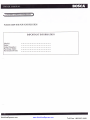
PLEASE KEEP THIS FOR YOUR RECORDS
IMPORTANT INFORMATION
Model:
Style:
Serial Number:
Purchase Date:
Purchased From:
NorthlineExpress.com
www.NorthlineExpress.com
Toll-Free 1-866-667-8454
BOSCA CHILE S.A.
Av. Am6rico Vespucio 2077
Huechuraba
Santiago - Chile
Telephone : (56) 2 3288500
Fax (56) 2 624189'
Made in Chile
NorthlineExpress.com
www.boscastoves.com
www.NorthlineExpress.com
Toll-Free 1-866-667-8454