1
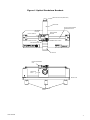
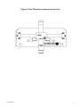
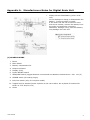
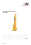
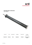
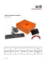
Optical Pendulum Readout User Manual Man 134 2.0.2 06/08/2014 C.Spalton Andy Small Chris Rasmussen Manual No. Revision Date Originator Checked Authorised for Issue User Manual 1 Contents Section 1 : Forward ...................................................................................................................... 3 Section 2 : Introduction ............................................................................................................... 3 Section 3 : Equipment .................................................................................................................. 5 3.01 3.02 3.03 Operation ..................................................................................................................... 5 Maintenance ................................................................................................................. 6 Battery Replacement ..................................................................................................... 6 Figure 1 Optical Pendulum Readout.................................................................................................. 7 Figure 2 Use Thumbs to traverse scale unit ...................................................................................... 8 Appendix A. User Manual Manufacturers Notes For Digital Scale Unit ................................................................ 9 2 Section 1 : Forward Soil Instruments Portable Readout is designed to read direct and inverted pendulum systems supplied by Soil Instruments Ltd. It is essential that the instrument covered by this manual is both operated and maintained by competent and suitably qualified personnel. Soil Instruments will not accept for repair under guarantee, instruments that have been neglected or mishandled in any way. User Manual 3 Section 2 : Introduction The Optical Pendulum Readout is designed to read direct and inverted pendulum systems. The readout comprises a manually focused telescope attached to a digital displacement measuring scale, all mounted on a self-locating base. The unit must be used in conjunction with Soil Instruments pendulum tables. The range of the instrument is ±75mm with a repeatability of 0.05mm and a resolution of 0.001mm. User Manual 4 Section 3 : Equipment The telescope is fitted, at one end, with an eyepiece containing a crosshair graticule, at the other end a fixed focus lens. A second lens is provided to increase the focal distance of the unit should it be necessary. Focusing is achieved by sliding the telescope through the mounting bush towards or away from the pendulum wire until a sharp focus is achieved. The measuring unit on which the telescope is mounted is moved along a slide by slight pressure of the thumb. See figure 2. As the measuring unit moves along the slide the distance from the origin is displayed digitally upon the screen of the measuring unit. The units of measurement are either millimeters or inches. There are facilities to set the origin and, reset the zero when required. The measuring unit and telescope are mounted on a base plate that self-locates on the mounting studs of the Soil Instrument’s Pendulum Tables. 3.01 Operation The Optical Pendulum Readout comes with batteries fitted and should be ready for operation. To check the unit is working, remove it from its carrying case and switch on the measuring unit (See figure 1). The liquid crystal display should come on and display a reading (normally mm). Check the units of measurement are those required, if not the units can be changed by pressing the button marked in/mm. Move the digital measuring unit to the extreme left of the slide unit until it comes up against the stop. Check that the reading is 0.00mm. If it is not, hold down the button marked origin for more than one second then release it. The reading should now be 0.00mm. This procedure should only be necessary on first time use of the instrument or if the battery is changed. Mount the reading unit on one set of the self-locating studs of the pendulum table. If not already done so, switch on the readout unit and move the telescope unit to the left until it comes up against the stop. Checking the reading, if it does not display 0.00in/mm use the zero ABS button to re-zero it. Move the telescope unit to the right until the pendulum wire is within the field of view of the telescope. Focus sharply on the wire by sliding the telescope in or out of the mounting bush. Once the wire is in focus, align the vertical crosshair on one edge of the pendulum wire. If the crosshair is not vertical rotate the eyepiece until it is so, if the telescope is fitted with a 45° or 90° angle viewer it is only possible to align the crosshair vertically if the viewer is in the vertical or horizontal plane. If the viewer is in any other plane the intersection of the crosshair should be used as the sighting point. Note the reading on the display. Move the telescope until the crosshair aligns on the opposite edge of the wire and note the second reading. The recorded reading should be the mean (average) of these two readings. For base or initial readings it is recommended that the above procedure is repeated three times, the base reading being the average. The above procedures are repeated for the second axis. User Manual 5 3.02 Maintenance It is essential that the equipment is kept clean at all times. The digital displacement measuring device works on the principle of counting interference patterns on the top of the slide bar. If the slide bar is dirty the measuring device will not work and an error message will appear on the screen (see appendix 1). If the slide bar becomes dirty, clean it with a mild degreasing agent or “WD40”. 3.03 Battery Replacement Battery type SR44 Silver Oxide. The battery life is better than 3 years under normal circumstances. To replace the battery remove the battery cover by pushing in the direction of the arrow (see Appendix 1). Remove the old battery and replace with the new one. Avoid touching the surfaces of the battery faces as this reduces the battery life. Note: It is necessary to reset the origin when the battery is replaced or the battery cover has been removed. For further information on the digital measuring unit see Appendix 1 User Manual 6 Figure 1 Optical Pendulum Readout FIXED FOCUS LENS (OBJECTIVE) x1 TELESCOPE DIGITAL DISPLACEMENT MEASURING SCALE SET UNITS BUTTON RESET ORIGIN BUTTON DIGITAL DISPLAY BATTERY COVER ON/OFF BUTTON SET ZERO BUTTON EYE PIECE DIGITAL MEASURING UNIT MOUNTING BUSH BASE PLATE SELF LOCATING STUDS User Manual 7 Figure 2 Use Thumbs to traverse scale unit User Manual 8 Appendix A. Manufacturers Notes for Digital Scale Unit Always use an SR44 battery (silver oxide cell). Do not attempt to charge or disassemble the battery. It may be short circuited. If the scale unit will not be used for more than three months, remove the battery from the scale unit and store it properly. Otherwise, leakage, if any, from the battery may damage the scale unit. (1) NOMENCLATURE 1 Beam 2 Main Switch 3 Battery compartment lid 4 Output connector 5 Display (LCD) 6 Power ON/OFF switch 7 ZERO/ABS switch (toggles between incremental and absolute measurement. See 8 ORIGIN switch (for setting origin) 9 Inch/mm switch (only for inch/mm model) sec.(5) 10 Tapped hole for bracket (bored 2 places on the rear surface, but 4 places for scales with Order no. 572-203/213-10) 11 Slider User Manual 9 (2) BATTERY INSTALLATION AND ORIGIN SETTING IMPORTANT Set up the origin of the scale after installing the battery. Otherwise, the error sign (“E” at the least significant digit, LSD) may appear, resulting in incorrect measurements. 1) Installing the Battery Remove the compartment lid and install the SR44 battery with its positive side facing up. TIP: Upon installation of the battery an arbitrary value or an E indicator will appear on the display. Ignore this display. Continue origin setting 2) Setting up the Origin After turning on the scale power switch, move the machine to its datum point then hold down the scale ORINGIN switch for more than one second. The “0.00” display appears, indicating Origin setting is complete. This origin will be retained even if the power is turned off. (3) INCREMENTAL (INC) MODE AND ABSOLUTE (ABS) MODE The LCD will display measurements from the origin when turned on (ABS mode). The display can be zero set at any desired position by pressing the ZERO/ABS switch. INC indicator appears in the display (INC mode), permitting measurement from the zero point. To restore measurements from the origin, hold down the ZERO/ABS switch for more than 2 seconds: INC indicator disappears from the LCD (ABS mode) while restoring the current position of the scale unit. (4) ERROR SYMPTOMS AND REMEDIES 1) ErrC and display flickering: Appears when the scale surface is contaminated. The surface of the scale should be cleaned and a small amount of low viscosity oil should be applied to repel water. 2) “E” at the LSD: Appears if the slider is moved at a high speed. measurement results. This does not affect Note: If “E” is displayed when the slider is not being moved, the calliper is in the same state as that of ErrC. Use the ErrC remedy. User Manual 10 3) “B” indicator: Appears when the battery voltage is low. Immediately replace the battery. (See sec.(2).) (5) SPECIFICATIONS Resolution: 0.01mm or 0.01mm/.0005” Repeatability: 0.01mm or 0.01mm/.0005” Maximum response speed: Unlimited (Miscount will not result due to slider speed.) Power supply: SR44 (Silver oxide cell) 1 piece Battery life: 3.5 years under normal operation Operating temperature: 00C to 400C Storage temperature: -100C to 600C Bell Lane, Uckfield, East Sussex t: +44 (0) 1825 765044 e: [email protected] TN22 1QL United Kingdom f: +44 (0) 1825 744398 w: www.itmsoil.com Soil Instruments Ltd. Registered in England. Number: 07960087. Registered Office: 5th Floor, 24 Old Bond Street, London, W1S 4AW User Manual 11